1
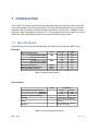
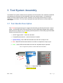
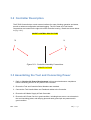
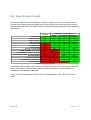
E-RAD Touch
User Manual
Revision 11/01
Rev: 01.02
1|P age
Contents
.......................................................................................................................................................... 1
Contents ............................................................................................................................................ 2
Product and Safety Notice .................................................................................................................. 4
1 Introduction ................................................................................................................................... 5
1.1 Specifications ................................................................................................................................... 5
2 Power Requirements ..................................................................................................................... 6
2.1 AC Mains Power................................................................................................................................ 6
2.2 Earth Grounding .............................................................................................................................. 7
2.3 Ground Fault Current Interrupt (GFCI) .............................................................................................. 7
2.4 Extension Cords ................................................................................................................................ 8
2.5 Power Cycling ................................................................................................................................... 8
3 Tool System Assembly ................................................................................................................... 9
3.1 Tool Handle Description ................................................................................................................... 9
3.2 Controller Description ..................................................................................................................... 10
3.3 Assembling the Tool and Connecting Power..................................................................................... 10
4 Touch Screen Interface ................................................................................................................ 12
4.1 Main Screen .................................................................................................................................... 13
4.2 User Access Levels ......................................................................................................................... 14
4.2.1 Unlocking the Tool ............................................................................................................... 15
4.2.2 Locking the Tool ................................................................................................................... 16
4.3 Tool Locked Functions..................................................................................................................... 16
4.3.1 Tool Locked Access .............................................................................................................. 17
4.3.2 Selecting a Preset ................................................................................................................ 17
4.3.3 Viewing Tool Information ..................................................................................................... 18
4.3.4 Changing the Log File ........................................................................................................... 19
4.3.5 Viewing the Log File ............................................................................................................. 21
4.3.6 Printing the Log File ............................................................................................................. 22
4.4 Basic Level Functions ...................................................................................................................... 23
4.4.1 Basic Level Access................................................................................................................ 23
Rev: 01.02
2|P age
4.4.2 Changing the Set Torque ...................................................................................................... 24
4.4.3 Changing the Set Angle......................................................................................................... 25
4.4.4 Saving a preset ..................................................................................................................... 26
4.5 Intermediate Level Functions .......................................................................................................... 27
4.5.1 Intermediate Level Access .................................................................................................. 27
4.5.2 Changing the Torque Units ................................................................................................... 28
4.5.3 Enabling / Disabling Angle Display Mode .............................................................................. 29
4.5.4 Enabling / Disabling Angle Lock ............................................................................................ 30
4.5.5 Enabling / Disabling Reverse Target Torque .......................................................................... 31
4.5.6 Viewing Tool Statistics ......................................................................................................... 32
4.5.7 Clearing Maintenance Statistics ............................................................................................ 33
4.6 Advanced Level Operations ............................................................................................................. 34
4.6.1 Advanced Level Access ........................................................................................................ 34
4.6.2 Enabling/Disabling Point Calibration ..................................................................................... 35
4.6.3 Configuring Point Calibration................................................................................................ 36
4.6.4 Tool Calibration .................................................................................................................... 37
4.6.5 Factory Configuration ........................................................................................................... 39
5 General Operating Instructions ...................................................................................................... 40
5.1 Safety Information .......................................................................................................................... 41
...................................................................................................................................................... 41
5.2 Torque Only Operation .................................................................................................................... 42
5.3 Angle Only Operation ...................................................................................................................... 44
5.4 Torque and Angle Operation ............................................................................................................ 46
5.5 Reviewing the last result .................................................................................................................. 47
6 Data Log PC Operations ................................................................................................................. 48
6.1 Software Installation and PC Requirements ..................................................................................... 48
6.2 Connecting PC and E-RAD ................................................................................................................ 48
6.3 Setting the Clock .............................................................................................................................. 51
6.4 Downloading all Data Logs ............................................................................................................... 51
6.5 Deleting (Closing) Data Logs............................................................................................................. 52
6.6 Exporting Data ................................................................................................................................. 53
Contact Us ....................................................................................................................................... 55
Rev: 01.02
3|P age
Product and Safety Notice
IMPORTANT:
DO NOT OPERATE THE TOOL BEFORE READING THIS
USER MANUAL. IF BREAKDOWN, MALFUNCTION OR
DAMAGE OCCURS, DO NOT ATTEMPT TO REPAIR.
CONTACT NEW WORLD TECHNOLOGIES INC. OR YOUR
LOCAL DISTRIBUTOR IMMEDIATELY.
Only persons trained and qualified should attempt the installation, operation and diagnosis of
this equipment. This equipment may be connected to high voltage AC mains power, and other
external equipment that has rotating parts controlled by this equipment. Improper training and
use can cause serious or fatal injury.
Intended use of this equipment is for commercial and industrial bolting applications. The tool
should only be used if the equipment is protected from exposure to excessive or corrosive
moisture, dust, dirt, ambient temperatures, vibration and impacts. The operating specifications
are in Section 1 of this manual. The installation, connection, and use requires skilled operation.
Dis-assembly or repair must not be attempted. If the equipments fails to operate correctly,
contact the distributor or manufacturer for instructions.
Rev: 01.02
4|P age
1 Introduction
The E-RAD Tool System is the world’s most advanced electronic pistol grip torque wrenches.
They are designed to provide a high degree of accuracy and repeatability using our patented,
legendary, gear box design combined using the precision of a servo motor. Capable of data
collection, angle measurement, accuracy of +/- 3% and torque values up to 6000 Ft.Lbs, the ERAD Series offer an affordable solution for precision electronic bolting needs.
1.1 Specifications
Please ensure that all Electrical specifications are used when utilizing the E-RAD Touch.
Electrical:
Units
Nominal Input Voltage
Minimum Input Voltage
Maximum Input Voltage
Nominal Tool Voltage
Minimum Tool Voltage
Maximum Tool Voltage
Nominal Input Current
Nominal Tool Phase Current
Peak Tool Phase Current
VAC
VDC
Arms
Arms
Arms
120V Model 230V Model
115
230
97
184
125
253
160
320
135
306
176
350
7.5
7.5
7.5
7.5
15
15
Table1: Electrical Specifications.
Environmental:
Units
Operating Temperature Range
Minimum
Maximum
Storage Temperature Range
Humidity
Shock
Vibration
%
All Models
degC
degF
0
32
40
104
-25 to 70
-13 to 158
10 to 90 non-condensing
10G according to DIN IEC
68-2-6/29
1G, 10-150Hz according to
DIN IEC 68-2-6/29
Table2: Environmental Specifications.
Rev: 11/01
5|P age
2 Power Requirements
This section provides instructions for connecting the AC Power Supply and Tool Handle to the
E-RAD Touch Controller.
The installer of this equipment is responsible for complying with Federal, NEC (National
Electrical Code) or equivalent, and local guidelines and application codes that govern
protection, earthing/grounding, disconnects and other current protection for electrical equipment
for use in indoor or outdoor applications.
2.1 AC Mains Power
WARNING!: Electrical Shock can cause serious or fatal injury. Do not touch
any power device , electrical connection or remove the E-RAD
cover panel before first ensuring the AC mains power has been
disconnected and no high voltage is present.
WARNING!: Ensure all AC mains wiring to the E-RAD power cord complies with the
National Electrical Code and all regional and local codes. Improper
wiring may result in unsafe conditions to equipment and personnel.
WARNING!: Ensure the correct AC mains voltage prior to connecting the AC mains
power. Severe equipment damage will occur if the E-RAD is connected
to the incorrect mains voltage.
The E-RAD Controller requires model specific single phase , 120AC or 230VAC.
The single phase line must be electrically symmetrical with respect to earth ground.
The branch circuit must be a dedicated 15A to ensure proper tool operation, and to avoid circuit
loading, nuisance trips.
The E-RAD Controller is internally fused for self protection. Please contact New World
Technologies Inc. for assistance if a blown fuse is suspected.
Rev: 11/01
6|P age
2.2 Earth Grounding
The E-RAD is assembled with a dedicated earth ground connection to the tool handle and
controller via the AC mains power connection.
It is the users responsibility to adhere, and follow at minimum, an Assured Grounding Program,
in addition to any and all National and Local Electrical Codes.
WARNING!: Earth grounding is the primary electrical shock protection, and is
mandatory!
WARNING!: Ensure E-RAD Controller and Tool Handle is properly Earth Grounded
before turning on the power switch. DO NOT turn on power to the tool
or operate the tool without verifying Earth Ground. Electrical Shock can
cause serious or fatal injury.
2.3 Ground Fault Current Interrupt (GFCI)
GFCI's are secondary protection devices, and protect against electric shock in case of a ground
wiring fault.
Standard Class A GFCI typically have a leakage current trip range of 4mA-6mA.
The E-RAD uses precision servo technology which inherently has higher leakage current than
the Class A GFI rating.
The E-RAD, when powered on, may have up to 4mA leakage current, and when loaded, may
have up to 19mA leakage current.
As a result of the leakage current the E-RAD may cause nuisance tripping of Class A GFCI
especially when loaded.
National and Local Electrical Codes may have an exclusion of GFCI requirements where an
appliance cannot be used with GFCI, if an Assured Grounding Program (AGP) is used and
maintained. Please check National and Local Electrical Code for compliance.
In addition to an Assured Grounding Program for personal protection, Class B GFCI, with a
leakage current trip rating of 20mA or greater. May be used for equipment protection on the ERAD.
Rev: 11/01
7|P age
2.4 Extension Cords
Extension cord quality and condition is important to ensure personal safety and E-RAD
performance. Please check National and Local Electrical Code for compliance.
For extension cords under 30ft, 12AWG is recommended.
For extension cords over 30ft, 10AWG is recommended.
Generally, 100ft is the maximum recommended length for any extension cord, although some
installations demand longer cords.
Longer extension cords will reduce the voltage and speed of the E-RAD Tool, and may cause
nuisance trips at higher torque demand.
2.5 Power Cycling
If AC power has been shut off from the E-RAD, it should not be reapplied for at least one
minute. This allows the input surge protection to perform properly. Power cycling more
frequently can cause nuisance trips and reduce the life-time of the electronics.
Rev: 11/01
8|P age
3 Tool System Assembly
The E-RAD Tool system consists of the Controller and Tool Handle. The controller and handle
are calibrated as a system and are identified by the same serial number. It is important to
always ensure the serial numbers match, otherwise the tool will perform torque or angle
operations in-accurately. This can cause equipment and joint failure due to under-torque or
over-torque.
3.1 Tool Handle Description
The E-RAD pistol grip torque gun is trigger activated with a bi-directional forward / reverse
switch. On the either side of the tool housing is a three LED Status Display which notifies
when the tool is ready for use, the bolting cycle has passed or if the bolting cycle has failed.
Details are shown below in (Fig. ----):
1. On/Off Trigger switch – hand tool activation.
2. Forward/Reverse switch – controls direction of rotation.
3. System Ready – Blue LED will illuminate when the tool is ready for use.
4. Fail – Red LED will illuminate when the tool fails to complete the torque cycle.
5. Pass – Green LED will illuminate when the tool completes torque operation.
Note: In Angle mode operation, all three LEDs will be illuminated.
3
2
4
1
5
Figure 3.1.1: Hand Held Tool
UPDATE PICTURE
Rev: 11/01
9|P age
3.2 Controller Description
The E-RAD Controller has a touch screen interface for ease of bolting operation and status,
as well as advance configuration and data logging. The AC Power and Tool Handle
Connections are located on the right side of the controller housing. Details are shown below
in (Fig. 3.2.1):
INSERT CONTROL BOX PICTURE
3
1
2
Figure 3.2.1: Controller Assembly Connections
UPDATE PICTURE
3.3 Assembling the Tool and Connecting Power
1. Refer to (Section 2.0) Power Requirements in this manual and ensure compliance
before connecting the tool or AC power to the controller.
2. Ensure the Tool and Controller Serial Numbers are matched.
3. Connect the Tool Handle Motor and Feedback cables to the Controller.
4. Ensure the AC Mains Supply is Earth Grounded.
5. Ensure the AC Power Cord is in good condition, including there are no cuts or breaks in
the cord insulating jacket, and the plug pins and earth ground pin are present and in
good condition.
Rev: 11/01
10 | P a g e
6. Ensure the E-RAD Power Switch is OFF and power light is off.
7. Connect the E-RAD AC Power Cord to the Controller.
8. Connect the E-RAD AC Power Cord to the AC Mains Supply.
9. Check that the E-RAD Controller and Tool Handle is properly Earth Grounded.
WARNING! Electrical shock can cause serious or fatal injury. Ensure E-RAD
Controller and Tool Handle are properly Earth Grounded before turning
on the power switch. DO NOT Turn on power to the tool or operate the
tool without verifying the Earth Ground.
10. E-RAD is ready for power on.
WARNING! DO NOT disconnect the electrical connectors while the E-RAD power is
ON. Damage to the tool or controller will occur.
Rev: 11/01
11 | P a g e
4 Touch Screen Interface
The E-RAD Touch provides simple user interface for bolting operations, with full tool
configuration options and advanced data log entry, recording, and retrieval.
For bolting management, and ease of use, basic user access can be locked or unlocked, and
intermediate and advanced configuration and calibration features are also password protected.
CAUTION!:
LCD Touch Displays are susceptible to mechanical shock and any
force exerted on the module may result is damage.
CAUTION!:
Moisture and water can damage the display when
powered. Wipe off any moisture gently or let the display
dry before usage.
CAUTION!:
Dirt from fingerprint oil and fat can easily stain the
surface of the display. Gently wipe off any stains with a
soft lint-free cloth.
CAUTION!:
The performance of the display will degrade under high
temperature and humidity. Avoid such conditions when
storing.
Rev: 11/01
12 | P a g e
4.1 Main Screen
The Main Screen is used as the central control point on the E-RAD Touch. Here the operator
can access the menu options, select Presets, change Set Torque and Set Angle and access the
the Data Logs. See Figure 4.1.1 for a visual description of the Touch Main Screen.
Logs Button
Lock/Unlock
Indicator
Current Date &
Time
Figure 4.1.1
Set Torque Button
Set Angle
Button
Menu Button
Rev: 11/01
Presets Button
13 | P a g e
4.2 User Access Levels
For bolting operation the tool will operate in locked or unlocked modes. The unlocked mode
provides user password access to additional functions. Each of the unlocked levels requires a
separate password. Refer to the table below for information which describes function availability
per use level.
Locked
Select Preset
Data Log Setup
Data Log View
Data Log Print
Modify Preset
Set Any Torque
Set Any Angle
Change Torque Units
Enable/Disable Angle Mode
Enable/Disable Angle Lock Mode
Enable/Disable Reverse Target Torque
Point Calibration
View Tool Statistics
Clear Maintenance Statistics
Tool Calibration
Yes
Yes
Yes
Yes
No
No
No
No
No
No
No
No
No
No
No
Password Unlocked Access
Basic
Intermediate
Advanced
Yes
Yes
Yes
Yes
Yes
Yes
Yes
Yes
Yes
Yes
Yes
Yes
Yes
Yes
Yes
Yes
Yes
Yes
Yes
Yes
Yes
No
Yes
Yes
No
Yes
Yes
No
Yes
Yes
No
Yes
Yes
No
Yes
Yes
No
Yes
Yes
No
Yes
Yes
No
No
Yes
Table3: User Access Levels
The E-RAD Touch is shipped from factory in the Basic Unlocked Level. It is recommended that
the tool be locked for normal bolting operations, after configuration, to avoid inadvertent
changes to tool settings and calibration.
Please refer to the appropriate manual section for further details on the individual function
usage.
Rev: 11/01
14 | P a g e
4.2.1 Unlocking the Tool
1)
To unlock the tool, press the “Menu” button on the main screen.
2)
Choose the “Unlock” option from the menu (Fig 4.2.1).
3)
A numeric keypad will be displayed in which you can enter the password for the desired
level (Fig 4.2.2). Refer to the appropriate user level section for further information on the
functions.
4)
Press “ENT” to confirm the password or “CLR” to undo any changes
5)
If the password is invalid you will see a “INCORRECT” message displayed on the
screen, otherwise the tool is now unlocked (Fig 4.2.3).
Figure: 4.2.1
Note:
Rev: 11/01
Figure: 4.2.2
Figure 4.2.3
When the tool is locked a padlock symbol is displayed in the top left corner of the screen
15 | P a g e
4.2.2 Locking the Tool
1)
To lock the tool, press the “Menu” button on the main screen.
2)
Choose the “lock” option from the menu (Fig 4.2.4).
3)
A numeric keypad will be displayed in which you can enter the
password: 37232 (Fig 4.2.5).
4)
Press “ENT” to confirm the password or “CLR” to undo any changes
5)
If the password is invalid you will see a “INCORRECT” message displayed on the
screen, otherwise the tool is now locked (Fig 4.2.6).
Figure: 4.2.4
Note:
Figure: 4.2.5
Figure 4.2.6
When the tool is locked a padlock symbol is displayed in the top left corner of the screen
4.3 Tool Locked Functions
This Section will explain how to perform some of the features the E-RAD has while in
Locked mode. Please refer to Table3 in Section 4.2 “User Access Levels” for more
information on the locked mode options.
Rev: 11/01
16 | P a g e
4.3.1 Tool Locked Access
Bolting operations are enabled in locked and any unlocked user level. If the tool is locked, the
user has access only to preset selections, tool info, and basic data log operations.
Refer to Section 4.2.1 “Unlocking the Tool” and Section 4.2.2 “Locking the Tool” for more
information.
4.3.2 Selecting a Preset
Presets allow the operator to access pre-defined toque and angle values quickly and efficiently.
This operation can be used in tool locked or unlocked mode.
To select a preset,
1.
Press the “Presets” button on the main screen.
2.
Select the desired preset by pressing the preselect
number button (Fig 4.3.1).
Figure: 4.3.1
Rev: 11/01
17 | P a g e
4.3.3 Viewing Tool Information
This screen can be viewed in tool locked or unlocked mode, and displays the following:
•
•
•
•
•
E-RAD Serial number
Controller Serial number
Factory Calibration Date
Customer Calibration Date (If Factory Calibration Modified)
Next Calibration Date (Based on 365 days after factory calibration date)
To view basic tool information,
1.
Press the “Menu” button on the main screen.
2.
Select “Tool Info” from the main menu screen
(Fig 4.3.2).
Figure: 4.3.2
Rev: 11/01
18 | P a g e
4.3.4 Changing the Log File
ATTENTION!: On E-RAD power-up, the data log file name will be set to “DEFAULT.LOG”. This
is to protect previous data log integrity. Therefore, if the E-RAD is powered off, or loses power
during a desired data set, the desired data log file name must be entered on power-up.
Changing the log file allows the operator to create/select a data log file name to record or view.
This operation can be used in tool locked or unlocked mode.
To create a new file name, or select an existing one,
1.
Press the “Folder” icon on the main screen.
2.
Choose “Select Log” from the data log menu (Fig 4.3.3).
3.
Enter the desired alpha-numeric file name using the keypad (Fig 4.3.4).
The keypad works similarly to a mobile phone for writing text messages.
4.
Press each key numerous times to cycle through the available characters of that key. If
you pause for more than 1 second, the cursor will move to the next position.
5.
Press “ENT” to accept the file name, or “CLR” to undo.
6.
If the log file name already exists, you will be prompted to continue the existing log, or
choose another file name (Fig 4.3.5).
7.
Once selected, the new file name is displayed on the main screen (Fig 4.3.6).
Note: The 1 key includes the characters ‘-‘, ‘_’, and ‘.’
To select the default log, you can choose “Select Default” from the “Data Log” menu
Rev: 11/01
19 | P a g e
Figure: 4.3.3
Figure: 4.3.5
Rev: 11/01
Figure 4.3.4
Figure: 4.3.6
20 | P a g e
Rev: 11/01
21 | P a g e
4.3.5 Viewing the Log File
Viewing the Log File will allow the operator to view the currently selected log file. Refer to
Section 4.3.4, to select a specific data log.
To view the current log file,
1.
Press the “Folder“ icon on the main screen.
2.
Choose “View Log” from the data log menu (Fig 4.3.7).
3.
Cycle between individual bolt cycle logs using the left and right arrow keys (Fig 4.3.8).
Figure: 4.3.7
Figure: 4.3.8
Note: Text will be in green if the cycle was a “Pass”, and red if the cycle was a “Fail”. If the operator prematurely
released the trigger during a torque cycle, the cycle will be recorded as a fail.
4.
Press Exit, to return to the main screen.
Rev: 11/01
22 | P a g e
4.3.6 Printing the Log File
Print the Log File allows the operator to print the selected log file to a serial printer, which is
optionally purchased. The recommended printer is Seiko DPU-414.
To print the current log file,
1.
Connect the serial printer to the communications port of the tool using the provided
E-RAD Programming Cable and Keyspan USB Adapter.
2.
Press the “Folder” icon on the main screen.
3.
Choose “Print Log” from the data log menu (Fig 4.3.9).
4.
Press “ENT” from the prompt window to start printing, or “CLR” to cancel (Fig 4.3.10).
5.
Once printing has started, do not disconnect the printer. To cancel printing at any time
by pressing the “Exit” button.
6.
Once printing is complete, press “Exit” button to return to the main screen.
Figure: 4.3.9
Rev: 11/01
Figure: 4.3.10
23 | P a g e
4.4 Basic Level Functions
This section will explain how to perform some of the features the E-RAD has while in Basic
Level. Please refer to Table3 in Section 4.2 “User Access Levels” for more information on
the Basic Level options.
4.4.1 Basic Level Access
To access the “Basic” level functions, enter password “37232”.
Generally, after operations are completed, lock the tool to ensure the settings are not
inadvertently modified.
Refer to Section 4.2.1 “Unlocking the Tool” and Section 4.2.2 “Locking the Tool” for more
information.
Rev: 11/01
24 | P a g e
4.4.2 Changing the Set Torque
Changing the Set Torque allows the operator to define the peak torque shut-off to any value
within the tool range. The torque units are displayed above the torque value on the main screen,
and cannot be changed from the basic level access.
To change the Set torque,
1.
Press the “Set Torque” button on the main screen.
2.
Enter the new target torque via the keypad. (Fig 4.4.1).
3.
Press “ENT” to confirm the new torque, or “CLR” to cancel.
4.
Confirm the new Set Torque is displayed on the main screen (Fig 4.4.2).
Figure: 4.4.1
Note:
Rev: 11/01
Figure: 4.4.2
The torque will automatically be adjusted if it is outside the maximum or minimum limits of the tool
25 | P a g e
4.4.3 Changing the Set Angle
Changing the Set Angle allows the operator to define the position shut-off to any value within 0360 degrees.
The angle mode is enabled from the the Intermediate or Advanced Level, and cannot be
enable/disabled from the basic level access.
If the angle is disabled, the target angle button and value will not be displayed.
To change the target angle,
1.
Press the “Set Angle” button on the main screen.
2.
Enter the new Set Angle via the keypad. (Fig 4.4.3).
3.
Press “ENT” to confirm the new angle, or “CLR” to cancel.
4.
Confirm the new Set Angle is displayed on the main screen (Fig 4.4.4).
Figure: 4.4.3
Note:
Rev: 11/01
Figure: 4.4.4
The angle will automatically be adjusted if it is outside the maximum or minimum limits of the tool. A
minimum angle of 10 degrees is required, and a maximum of 360 degrees.
26 | P a g e
4.4.4 Saving a preset
Presets provide quick selection of up to eight pre-defined target sets of torque and angle (if
enabled). These presets can only be modified when the tool is unlocked from any access level.
In this manner, the presets can be configured and the tool locked to prevent inadvertent
changes during normal operation.
To modify and save a Preset,
1.
Modify the target torque as per Section 4.4.2, and/or the target angle as per
Section 4.4.3.
2.
Press the “Presets” menu button on the main screen.
3.
Choose “Save Preset” from the preset menu (Fig 4.4.5).
4.
Select the desire Preset Number, via the keypad, to save the current target torque/angle
values to (Fig 4.4.6).
Note:Saving the values overwrites any existing presets stored in that location.
5.
Press “ENT” to confirm the preset location or “CLR” to cancel.
Figure: 4.4.5
Rev: 11/01
Figure: 4.4.6
27 | P a g e
4.5 Intermediate Level Functions
This section will explain how to use the Intermediate functions on the E-RAD. Please refer
to Table3 in Section 4.2 “User Access Levels” for an overview of the Intermediate Level
options.
4.5.1 Intermediate Level Access
To access the following functions you must have access to the “Intermediate” level password,
and unlock the tool with that password. Generally, after operations are completed, lock the tool
to ensure the settings are protected and cannot be inadvertently modified.
Please contact New World Technologies Inc. for the password.
Refer to Section 4.2.1 “Unlocking the Tool” and Section 4.2.2 “Locking the Tool” for more
information.
Rev: 11/01
28 | P a g e
4.5.2 Changing the Torque Units
The torque units can be selected from ft-lbs, Nm, or Kgfm. When the units are changed, the Set
Torque value, presets torque values, and calibration values are automatically adjusted to the
selected units.
To change the torque units,
1.
Press the “Menu” button on the main screen.
2.
Select “Change Units” from the second page of the menu (Fig 4.5.1).
3.
Select the desired units (Fig 4.5.2).
Figure: 4.5.1
Rev: 11/01
Figure: 4.5.2
29 | P a g e
4.5.3 Enabling / Disabling Angle Display Mode
The Angle Display Mode can be enabled or disabled (if factory enabled) by the user. When
enabled the target angle is displayed and accessible to the operator.
WARNING! This feature should only be used by an operator who is fully
trained on this feature. Improper use can cause serious harm to
the operator and the equipment. Please contact NWT for more
information.
To change the angle mode,
1.
Press the “Menu” button on the main screen
2.
Select the “User Config” from the main menu (Fig 4.5.3).
3.
Select “Angle On” or “Angle Off”. This feature is enabled if the Angle Mode Off
selection is displayed (Fig 4.5.4).
Figure: 4.5.3
Rev: 11/01
Figure: 4.5.4
30 | P a g e
4.5.4 Enabling / Disabling Angle Lock
The Angle Lock feature allows the operator to release the trigger during an angle move, and the
tool will continue to operate and complete the angle move unless the tool is placed into reverse.
This may be desired to alleviate operator fatigue during long angle moves.
To change the angle lock,
1.
Press the “Menu” button on the main screen.
2.
Select the “User Config” from the main menu (Fig 4.5.5).
3.
Select “Angle Lock On” or “Angle Lock Off”. This feature is enabled if the Angle
Lock Off selection is displayed. (Fig 4.5.6).
Figure: 4.5.5
Rev: 11/01
Figure: 4.5.6
31 | P a g e
4.5.5 Enabling / Disabling Reverse Target Torque
The reverse target torque feature allows the tool to target torque in reverse, as well as is in
forward mode.
To change the reverse target torque mode,
1.
Press the “Menu” button on the main screen.
2.
Select the “User Config” from the main menu (Fig 4.5.7).
3.
Select “Rev. Trgt On” or “Rev. Trgt Off”. This feature is enabled if the Rev. Trgt Off
selection is displayed. (Fig 4.5.8).
Figure: 4.5.7
Rev: 11/01
Figure: 4.5.8
32 | P a g e
4.5.6 Viewing Tool Statistics
The Tool Statistics displays the tool Life Cycle Counters, Maintenance Counters, and Error
Logs.
The life cycle counters cannot be cleared, and are for factory use.
The maintenance counters can be cleared from the Intermediate or Advanced Access levels
only, and are for use by the user.
To view the tool statistics,
1.
Press the “Menu” button on the main screen.
2.
Select “Tool Stats” from the menu (Fig 4.5.9).
3.
Select “Life Stats” from the menu, to view the life cycle counters(Fig 4.5.10).
Select “Maint Stats” from the menu to view the counters since last clear (Fig 4.5.11).
Figure: 4.5.9
Rev: 11/01
Figure: 4.5.10
Figure: 4.5.11
33 | P a g e
4.5.7 Clearing Maintenance Statistics
The maintenance statistics can be cleared from the Intermediate or Advanced Access levels
only, and are for use by the user as desired.
To clear the maintenance statistics,
1.
Press the “Menu” button on the main screen.
2.
Select “Tool Stats” from the second page of the menu (Fig 4.5.12).
3.
Select “Clear Maint” from the menu (Fig 4.5.13).
4.
Press “CONFIRM CLR” to confirm or “EXIT” to cancel (Fig 4.5.14).
Figure: 4.5.12
Rev: 11/01
Figure:4.5.13
Figure:4.5.14
34 | P a g e
4.6 Advanced Level Operations
This section will explain how to use the Advanced functions on the E-RAD. Please refer to
Table3 in Section 4.2 “User Access Levels” for an overview of the Advanced Level
options.
4.6.1 Advanced Level Access
To access the following functions the user must have access to the “Advanced” level
password, and unlock the tool with that password. Generally, after operations are completed,
lock the tool to ensure the settings are protected and cannot be inadvertently modified.
Please contact New World Technologies Inc. for the password.
Refer to Section 4.2.1 “Unlocking the Tool” and Section 4.2.2 “Locking the Tool” for more
information.
Rev: 11/01
35 | P a g e
4.6.2 Enabling/Disabling Point Calibration
Point Calibration is used to quickly adjust the tool final torque for a single Set Torque only. This
is generally used for field application torque verification and adjustment. The point calibration
adjustment is only valid when Point Calibration is enabled, and only for the single Set Torque.
The point calibration does not overwrite the tool calibration values.
To enable point calibration,
1.
Press the “Menu” button on the main screen.
2.
Select the “User Config” from the main menu (Fig 4.6.1).
3.
Select “Point Cal” to enable Point Calibration (Fig 4.6.2) or “Exit Point Cal” to disable
Point Calibration from the menu.
4.
If Point Calibration is enabled, a Target Icon will be shown on the top left corner of the
main menu display screen. (Fig 4.6.3).
5.
Perform target torque calibration, refer to Section 4.6.3 “Configuring Point
Calibration”.
Figure: 4.6.1
Rev: 11/01
Figure: 4.6.2
Figure: 4.6.3
36 | P a g e
4.6.3 Configuring Point Calibration
Point Calibration is used to quickly adjust the tool calibration for a single Set Torque only, to
match the final torque shut-off to a secondary verification system. The user will need a
calibration stand to perform this procedure.
To configure point calibration,
1.
Ensure Point Calibration is enabled. Refer to Section 4.6.2 “Enabling/ Disabling
Point Calibration” for more information.
2.
Mount the tool system to a calibration system and ensure the calibration transducer
display is configured in the same torque units as the tool.
3.
Press the target torque value button from the main screen.
4.
Enter the desired target torque via the keypad (Fig 4.6.4).
5.
At the prompt “Do Torque Cycle 1” (Fig 4.6.5), operate the tool to complete the first
torque cycle.
6.
Enter the calibration transducer measured torque result via the keypad.
7.
At the prompt “Do Torque Cycle 2” (Fig 4.6.6), operate the tool to complete the second
torque cycle.
8.
Enter the calibration transducer measured torque result via the keypad.
9.
The main screen will be displayed and the point calibration adjustment will be saved.
The tool torque will be adjusted by the point calibration, for the specific target torque,
until a new target it entered, or the point calibration is disabled.
10.
Lock the tool to ensure the target torque is not inadvertently changed for the point
calibration modified. Refer to Section 4.2.2 “Locking the Tool”.
11.
The tool can now be used for the intended application.
Rev: 11/01
37 | P a g e
Figure: 4.6.4
Figure: 4.6.5
Figure: 4.6.6
4.6.4 Tool Calibration
The tool calibration provides access to the calibration values over the full range of the tool, and
should only be modified by a qualified Calibration Technician.
WARNING!
Calibration must only be done be qualified
Calibration Technician. Improper use of this
function and calibration can lead to tool and/or
joint failure.
The calibration values represent the relationship between tool output power and torque in
standard engineering torque units. The torque units can be modified, refer to Section 4.5.2
“Changing Torque Units” for more information.
When the calibration is modified by the user, the date is stored. When the calibration is
modified by NWT or an authorized NWT Distributor, the factory calibration date, and
recommended calibration due date is stored. Refer to Section 4.5.6 “Viewing Tool
Information” for more information.
To calibrate the tool,
1.
Press the “Menu” button on the main screen.
2.
Select the “User Config” from the main menu (Fig 4.6.7).
3.
Select “Calibration” from the menu (Fig 4.6.8). A Confirmation Window will appear
asking to confirm the calibration or cancel the Calibration (Fig 4.6.9)
4.
Do several torque cycles at the target 7% tool capacity, and average the results
measured by a certified strain gauge transducer.
Rev: 11/01
38 | P a g e
5.
Press the “Cal Value” button (Fig 4.6.10), and enter the averaged measured torque via
the numeric keypad. After the value is entered, the target tool capacity will
automatically increment.
6.
Repeat steps 4 and 5 for each target tool capacity (in percentage), until the maximum
tool torque is met or slightly exceeded.
WARNING!
7.
Do not calibrate at targets that result in
exceeding the maximum rated tool torque.
Sever tool damage will occur.
Press “Exit”, and at the prompt press “CLR” to discard changes and “ENT” to save
them. (Fig 4.6.11)
Note: Any calibration target can be reviewed and modified by using the left and right arrow
buttons on the bottom of the calibration screen.
Figure: 4.6.7
Figure: 4.6.10
Rev: 11/01
Figure: 4.6.8
Figure: 4.6.9
Figure: 4.6.11
39 | P a g e
Rev: 11/01
40 | P a g e
4.6.5 Factory Configuration
Factory Configuration is used to adjust factory settings including minimum torque, maximum
torque, angle mode, and gearbox ratio. This setting can only be used under the the direction of
NWT representative and with NWT provided codes.
Please contact New World Technologies Inc. for more information.
Rev: 11/01
41 | P a g e
5 General Operating Instructions
RAD TOOLS ARE SAFE AND RELIABLE. NOT
FOLLOWING PRECUATIONS AND INSTRUCTIONS
OUTLINED HERE CAN REUSLT IN INJURY TO YOU
AND YOUR FELLOW WORKERS
NEW WORLD TECHNOLOGIES INCORPRATED IS NOT
RESPONBIBLE FOR ANY SUCH INJURY.
WARNING!: Do not operate tool before reading this user manual.
If breakdown, malfunction, or damage occurs, DO NOT
attempt to repair. Contact New World Technologies Inc.
or your local distributor immediately.
WARNING!: Ensure E-RAD controller and tool handle is properly earth
grounded before turning on the power switch. DO NOT
apply power without verifying the Earth Ground. Electrical
Shock can cause serious or fatal injury.
WARNING!: Electrical Shock can cause serious or fatal injury. Do not
touch any power device , electrical connection or remove
the E-RAD cover panel before first ensuring the AC mains
power has been disconnected and no high voltage is present.
When using a power plug adapter, make sure the earth
ground pin is present and connected into the adapter. New
World Technologies Inc. does not recommend replacing the
supplied power cord. In the event the power cord is replaced,
sure the new power cord has an earth ground pin.
CAUTION!:
Rev: 11/01
make
42 | P a g e
5.1 Safety Information
E-RAD Tools use high voltage and current to tighten and loosen threaded fasteners. For your
safety and that of others, WARNING LABELS and ATTENTION LABELS are prominently
attached to the tool and reaction accessories.
E-RAD Tools have been designed with safety in mind however as with all tools you MUST
observe all general workshop safety practices and specifically the following;
1.
2.
3.
4.
Before using your new tool, read this manual in full, and get familiar
with all tool accessories and how they work.
ALWAYS wear safety goggles when the tool is in operation.
Make sure the reaction arm is in contact with a solid contact point
before you operate the tool.
Keep your body parts clear of the reaction arm and the contact point.
Fig 5.1.1 – Reaction Arm Point
5.
6.
7.
8.
Rev: 11/01
ALWAYS check that the AC Mains Supply, E-RAD Controller ,and ERAD Tool handle are properly Earth Grounded. DO NOT apply power to
the tool if you are unsure.
NEVER exceed the maximum tool rated torque. Failure to do this voids
warranty.
Make sure the reaction arm snap ring is securely in place to hold the
reaction arm or blank in place
ALWAYS support the tool in use. The tool must be supported at all
times in order to prevent unexpected release in the event of fastener or
component failure.
43 | P a g e
5.2 Torque Only Operation
This section describes the general operation of the E-RAD Torque Only mode.
WARNING!: Only qualified personnel with training in the safe operation of torque
tooling and E-RAD tool system should operate the tool. Refer to
Section 5.1 “Safety Information” for more information.
To use Torque Only,
1)
Adjust the Set Torque to the desired value using the Main screen (Fig 5.2.1). If the tool is
locked, refer to Section 4.3.2 “Selecting a Preset”.
If the tool is unlocked refer to Section 4.4.2 “Changing the Set Torque” for more
information on how to set the Torque to its desired value.
2)
If Angle Mode is enabled, Adjust the Set Angle to zero.
3)
Place the tool on the joint system, and switch the tool handle direction selector to
forward.
4)
Ensure the tool handle “System Ready” LED is illuminated.
5)
Press and hold the tool handle trigger until the torque cycle has completed. To stop the
tool at any time during the cycle, release the trigger.
6)
When the torque cycle is completed or canceled the measured peak torque will be
displayed on the screen. Figure 5.2.2 shows the display screen when the bolt was
successfully torqued, Figure 5.2.3 when the bolt was unsuccessfully torqued.
The result will remain displayed for ten seconds, until the tool is reversed or a new
cycle started. Once the torque cycle is completed the tool will automatically reverse
to release the tool from the join. At this point the tool handle “Pass” LED will be
illuminated.
Rev: 11/01
44 | P a g e
Figure: 5.2.1
Note:
Rev: 11/01
Figure: 5.2.2
Figure: 5.2.3
After the tool has finished moving forward, it will back off slightly to unload the reaction arm.
45 | P a g e
5.3 Angle Only Operation
This section describes the general operation of the E-RAD Angle Only mode.
WARNING!: Only qualified personnel with training in the safe operation of torque
tooling and E-RAD tool system should operate the tool. Refer to
Section 5.1 “Safety Information” for more information.
1)
Set the Torque to '0' Ftlb and the angle to the desired angle(Fig 5.3.1). If the tool is
locked, refer to Section 4.3.2 “Selecting a Preset”.
If the tool is unlocked refer to Section 4.4.2 “Changing the Set Torque” and Section 4.4.3
“Changing the Set Angle” for more information on how to set the Torque and Angle to
their desired values.
2
Place the tool on the joint system, and switch the tool handle direction selector to
forward.
3)
Ensure the tool handle “System Ready” LED is illuminated.
4)
Hold the trigger down, The tool will pause to complete the pre-torque (Fig 5.3.2). Press
and hold the trigger again to complete the angle.
5)
As the bolt is tightened the display will be updated with the current angle.
6)
When the tool stops moving the result of the angle will be displayed on the screen.
Figure 5.3.3 shows the display screen when the bolt was successfully torqued in angle
only operation.
The result will remain displayed for 10 seconds, until the tool is reversed, or a new
torque cycle starts
7)
Once “Pass” or “Fail” has been displayed the tool is ready to perform another torque
Rev: 11/01
46 | P a g e
Figure 5.3.1
Note:
Rev: 11/01
Figure 5.3.2
Figure 5.3.3
After the tool has finished moving forward, it will back off slightly to unload the reaction arm.
47 | P a g e
5.4 Torque and Angle Operation
This section describes the general operation of the E-RAD Torque and Angle mode.
WARNING!: Only qualified personnel with training in the safe operation of torque
tooling and E-RAD tool system should operate the tool. Refer to
Section 5.1 “Safety Information” for more information.
1)
Adjust the Set Torque and Set Angle to the desired values using the Main screen
(Fig 5.4.1). If the tool is locked, refer to Section 4.3.2 “Selecting a Preset”.
If the tool is unlocked refer to Section 4.4.2 “Changing the Set Torque” and Section 4.4.3
“Changing the Set Angle” for more information on how to set the Torque and Angle to their
desired values.
2)
Hold the trigger down until the torque has completed. To stop the tool at any time
during the cycle, release the trigger.
3)
Initially the tool will ramp up to the Pre-Torque value.
4)
After the Pre-torque has been reached the tool will pause for a moment before
continuing with the angle move.
5)
When the tool stops moving the result of the angle will be displayed on the screen.
Figure 5.4.2 shows the display screen when the bolt was successfully torqued in angle
only operation while Figure 5.4.3 shows when the bolt was unsuccessfully torqued.
The result will remain displayed for 10 seconds, until the tool is reversed, or a new
torque cycle starts.
6)
Once “Pass” or “Fail” has been displayed the tool is ready to perform another torque
cycle
Rev: 11/01
48 | P a g e
Figure: 5.4.1
Figure: 5.4.2
Figure: 5.4.3
Note:
Once the tool has reached the set pre-torque value it will pause for a second before starting the
angle move. After the tool has finished moving forward, it will back off slightly to unload the reaction arm.
5.5 Reviewing the last result
Reviewing the last result allows the operator to view the last torque cycle that the ERAD Touch
performed. This operation can be used in tool locked or unlocked mode.
1)
The result of the last bolt torqued is accessible by touching the “Last Result” text
displayed above the set torque parameter (Fig 5.5.1).
2)
Once touched, the last result is displayed for 10 seconds, until the tool is reversed, or a
new torque cycle starts (Fig 5.5.2).
Rev: 11/01
49 | P a g e
Figure: 5.5.1
Figure: 5.5.2
6 Data Log PC Operations
Using the E-RAD Data Logger the operator is able to connect an E-RAD Touch to a Personal
Computer (PC or Laptop). Once in PC Mode the operator can perform the following actions:
−
−
−
−
Setting the Clock on the E-RAD Touch
Downloading all Data Logs off of the E-RAD Touch
Deleting (close) Data Logs on the E-RAD Touch
Export Data to another program
6.1 Software Installation and PC Requirements
Every E-RAD is shipped with software and hardware required for PC connection. The following
equipment will be used in this section:
−
−
−
E-RAD Software Package CD.
E-RAD Serial Cable and Keyspan USB-Serial Adapter
Keyspan USB-Serial Apapter CD
The E-RAD Data Logger Software is compatible with Windows 7, Vista and XP operating
systems.
Please follow the readme.txt file on the CD for instructions on installing the E-RAD software on
the PC.
Please follow the Keyspan CD instructions for installing the adapter drivers.
Rev: 11/01
50 | P a g e
6.2 Connecting PC and E-RAD
To connect the E-RAD to the PC for data log access,
1. Ensure the E-RAD software and Keyspan software is installed.
2. Locate the E-RAD Serial Cable and Keyspan USB-Serial Adaptor (Fig 6.2.1).
3. Connect the E-RAD Serial Cable, RJ45 Connector to the Comms Port on the E-RAD
Controller.
4. Connect the E-RAD Serial Cable, DB-9 Connector to the Keyspan USB-Serial Adapter.
5. Connect the Keyspan USB-Serial Adapter USB Connector to the PC.
6. On the E-RAD press the “Menu” button on the main screen.
7. Select “PC Interface” from the first page of the menu (Fig 6.2.2).
8. The “PC Mode” screen is now displayed. (Fig 6.2.3).
9. On the PC open the RAD Torque “E-RAD Data Logger” software. (Fig 6.2.4).
10. Select the correct Com Port for the connection (Fig 6.2.5) using the Options drop down
menu.
Figure 6.2.1 WRONG PICTURE
Rev: 11/01
51 | P a g e
Figure: 6.2.2
Note:
Figure: 6.2.3
Please ensure you are using the correct Data logger for the E-RAD Touch. Refer to Step 4 on the
installation CD for further details.
Figure: 6.2.4
Rev: 11/01
52 | P a g e
Figure: 6.2.5
6.3 Setting the Clock
The E-RAD Data Logger is used to set the time on the E-RAD Touch Controller for data log
timestamps.
1)
To set the clock, first enter “PC Mode”, see Section 6.2 “Connecting PC and E- RAD”
for more information.
2)
On the PC open the RAD Torque “E-RAD Data Logger” software.
3)
Under the options drop down menu located in the E-RAD Data Logger” Software select
“Set RTC” this will update the clock with the current time on the PC.
6.4 Downloading all Data Logs
Rev: 11/01
53 | P a g e
Using the E-RAD Data Logging Software, the operator is able to download all Data logs from
the E-RAD Touch to the PC.
1)
To download all data logs, first enter “PC Mode” on the E-RAD, see Section 6.2
“Connecting PC and E-RAD” for more information.
2)
On the PC open the RAD Torque “E-RAD Data Logger” software.
3)
Press the “Update Logs” button on the main screen (Fig 6.4.1).
4)
The PC Program will download all the logs from the tool.
5)
Once the logs have been downloaded, you may be prompted to add descriptions of the
tool and the data logs. These descriptions can be anything to help identify the data.
Figure: 6.4.1
Note:
All data is stored on a local database which may be queried to further manipulate the data.
6.5 Deleting (Closing) Data Logs
Closing Data Logs allows the operator to remove the logs from the E-RAD Touch. This
information will remain on the PC. The title of the Closed log will also be automatically modified
to represent the date it was closed.
1)
To delete a data log, first enter “PC Mode”, see Section 6.2 “Connecting PC and ERAD” for more information.
Rev: 11/01
54 | P a g e
2)
On the PC open the RAD Torque “E-RAD Data Logger” software.
3)
Select the log you wish to close (Fig 6.5.1).
Figure: 6.5.1
4)
Under the options menu choose “Close Log” (Fig 6.5.2).
5)
The selected log will be closed in the database and deleted from the tool.
Figure: 6.5.2
6.6 Exporting Data
Using the Exporting Data feature the operator is able to transfer data to another program.
1)
To transfer data to another program, first select the tool you wish to get the data from
(Fig 6.6.1).
Rev: 11/01
55 | P a g e
Figure: 6.6.1
2)
Then select the log that you wish to retrieve the data from (Fig 6.6.2).
Figure: 6.6.2
3)
With the drag of the computer mouse select all the data you wish to export, press
Control + C to copy it. Go to the other program such as Notepad, Word pad or Microsoft
Word and press Control + V to paste the data into the other program (Fig 6.6.3).
Rev: 11/01
56 | P a g e
Figure: 6.6.3
Contact Us
New World Technologies Inc.
30580 Progressive Way
Abbotsford, B.C.
V2T 6Z2
Canada
Toll Free: 1-800-983-0044
Fax: 604-852-0269
ERAD Technical Support: 1-604-852-0405, ext. 227
web: www.eradtorque.com
Rev: 11/01
57 | P a g e
Rev: 11/01
58 | P a g e