1
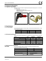
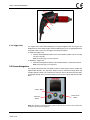
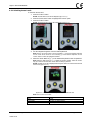
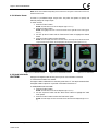
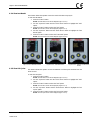
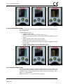
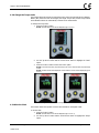
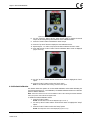
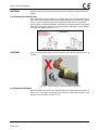
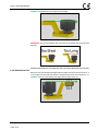
DIGITAL V-RAD USER MANUAL
LEADING MANUFACTURER OF ADVANCED TORQUE SYSTEMS
PNEUMATIC
BATTERY
ELECTRONIC
ELECTRIC
TRANSDUCER
Digital V-RAD USER MANUAL
TABLE OF CONTENTS
TABLE OF CONTENTS ..................................................................... 1
IMPORTANT SAFETY NOTICE ......................................................... 2
1.0 General Information ................................................................ 3
1.1 System Components ................................................................... 3
1.2 Specifications ............................................................................. 3
1.2.1 Torque Ranges ................................................................................3
1.2.2 Electrical Specifications ....................................................................3
1.2.3 Environmental Specifications ............................................................3
2.0 Power Requirements ............................................................... 4
2.1 AC Mains Power.......................................................................... 4
2.2 Earth Grounding Safety ............................................................... 4
2.3 Ground Fault Current Interrupt (GFCI).......................................... 4
2.4 Extension Cords.......................................................................... 4
3.0 Tool System ............................................................................. 4
3.1 Tool Handle ............................................................................... 4
3.1.1 Trigger Lock....................................................................................5
3.2 Screen Navigation ....................................................................... 5
4.0 LCD Display Interface .............................................................. 6
4.1 Main Screen ............................................................................... 6
4.2 User Access Levels ...................................................................... 6
4.2.1 Unlocking Access Levels...................................................................7
4.2.2 Returning to the Locked Level ..........................................................8
4.3 Functions ................................................................................... 8
4.3.1 Select a Preset ................................................................................9
4.3.2 Hard Joint Mode ..............................................................................9
4.3.3 View Tool Information ................................................................... 10
4.3.4 View Last Result ............................................................................ 11
4.3.5 View Life Cycles ............................................................................ 11
4.3.6 View Maintenance Cycles ............................................................... 12
4.3.7 Change the Target Torque ............................................................. 12
4.3.8 Save a Preset ................................................................................ 13
4.3.9 Change the Torque Units ............................................................... 14
4.3.10 Set the Clock ............................................................................... 14
4.3.11 Clear Maintenance Cycles ............................................................. 15
4.3.12 Tool Calibration ........................................................................... 16
4.3.13 Default Calibration ....................................................................... 17
5.0 General Operating Instructions ............................................. 18
5.1 Reaction Arm ........................................................................... 18
5.1.1
5.1.2
5.1.3
5.1.4
Installing the Reaction Arm ............................................................ 19
Reaction Arm Height ..................................................................... 19
Reaction Arm Foot ......................................................................... 20
Reaction Points ............................................................................. 21
5.2 Torque Operation ..................................................................... 21
6.0 Errors ..................................................................................... 22
7.0 CONTACT US .......................................................................... 23
New World Technologies Inc.
V2014.07.04
Page • 1
Digital V-RAD USER MANUAL
IMPORTANT SAFETY NOTICE
RAD TOOLS ARE SAFE AND RELIABLE. NOT FOLLOWING PRECUATIONS AND
INSTRUCTIONS OUTLINED HERE CAN RESULT IN INJURY TO THE TOOL,
OPERATOR AND FELLOW WORKERS.
NEW WORLD TECHNOLOGIES INCORPRATED IS NOT RESPONSIBLE FOR ANY
SUCH INJURY.
The intended use of the Digital V-RAD Tool System is for commercial and industrial bolting
applications.
Do not operate the Digital V-RAD Tool System before reading and understanding this user
manual and noting the Safety Notices displayed on the Digital V-RAD Tool System and
throughout this manual.
Only qualified personnel with training in the safe operation of torque tooling and the Digital
V-RAD Tool System should attempt the installation, operation and diagnosis of the Digital VRAD Tool System.
The Digital V-RAD Tool System is connected to high voltage power and consists of external
rotating parts. Improper training and use can cause serious or fatal injury.
Do not disassemble or attempt to repair the Digital V-RAD Tool System; doing so will void
warranty. If breakdown, malfunction or damage occurs and the Digital V-RAD Tool System
fails to operate correctly, contact New World Technologies Inc. Technical Support (refer to
Section 7.0 – Contact Us).
The Digital V-RAD Tool System should only be used if environmental storage and operation
specifications have been met. Refer to Section 1.2.3 – Environmental Specifications.
Electrical Shock can cause serious or fatal injury. Do not apply power to the Digital V-RAD
Tool System without verifying the Earth Ground.
Ensure all AC Mains Power wiring to the Digital V-RAD comply with all National and Local
Electrical Codes. Improper wiring may result in unsafe conditions for equipment and
personnel.
Do not operate the Digital V-RAD Tool System in explosive atmospheres, including, but not
limited to, the presence of flammable liquids, gases or dust. The Digital V-RAD Tool System
creates sparks which could ignite these substances.
Do not expose the Digital V-RAD Tool System to wet conditions. Water in the Digital V-RAD
Tool System will cause damage to the tool and increase the risk of electric shock.
After long durations of use, the Digital V-RAD Tool System will become hot. It is
recommended to use the tool in short intervals and allow for cooling between uses to prevent
injury to the operator or damage to the Digital V-RAD Tool System.
While operating the Digital V-RAD Tool System, always wear safety goggles and keep all body
parts clear of moving parts and the reaction arm contact point.
Never exceed the Maximum Torque of the Digital V-RAD Tool System. Failure to comply will
result in void warranty.
The V-RAD Tool System has been calibrated by a qualified Calibration Technician; calibration
must be done by a qualified Calibration Technician. Improper calibration can cause damage
to the tool and joint.
New World Technologies Inc.
V2014.07.04
Page • 2
Digital V-RAD USER MANUAL
1.0 General Information
1.1 System Components
The Digital V-RAD Tool System is shipped from New World Technologies Inc. in a case with
the following parts:
Digital V-RAD Tool (Figure 1.1-1)
Standard Reaction Arm and Snap Ring (Figure 1.1-2)
Calibration Certificate
User Manual
Figure 1.1-1: Digital V-RAD Tool
Figure 1.1-2: Standard Reaction Arm
Note: Some distributors may ship additional parts along with the Digital V-RAD Tool System.
1.2 Specifications
1.2.1 Torque Ranges
The following table outlines the torque ranges, in Foot-Pounds and Newton-Meters, of each
Digital V-RAD Tool System:
DV-RAD 1000
DV-RAD 1500
DV-RAD 2500
Imperial
400-1000 FtLb
600-1500 FtLb
1000-2500 FtLb
Table 1.2.1:
Metric
or
DV-RAD 1350
or
DV-RAD 2000
or
DV-RAD 3390
Torque Ranges
550-1350 Nm
800-2000 Nm
1350-3400 Nm
1.2.2 Electrical Specifications
Ensure that all Electrical Specifications are followed when utilizing the Digital V-RAD Tool
System.
Units
VAC
VAC
VAC
VDC
VDC
120V Model
120
108
133
170
153
230V Model
230
185
260
325
262
VDC
188
368
ARMS
8.1
W
900
Table 1.2.2: Electrical Specifications
4.2
900
Nominal Input Voltage
Minimum Input Voltage
Maximum Input Voltage
Nominal Tool Voltage
Minimum Tool Voltage
Maximum Tool Voltage
Nominal Input Current
Nominal Input Power
1.2.3 Environmental Specifications
CAUTION!
Only operate the Digital V-RAD Tool System if the following environmental storage
and operation specifications have been met.
Temperature Ranges
Operating Temperature
Storage Temperature
Humidity
Shock
Vibration
Required Operating Conditions
̊C
̊F
0 – 40
32 – 104
-25 – 70
-13 – 158
10% to 90% non-condensing
10G according to DIN IEC 68-2-6/29
1G, 10-150Hz according to DIN IEC 68-2-6/29
Non explosive atmosphere
Dry location
Table 1.2.3: Environmental Specifications
New World Technologies Inc.
V2014.07.04
Page • 3
Digital V-RAD USER MANUAL
2.0 Power Requirements
The installer of this equipment is responsible for complying with National Electrical Code
(NEC) or equivalent Federal and Local Guidelines and Application Codes that govern
protection, earth grounding, disconnects and other current protection for electrical equipment
for use in outdoor or indoor applications.
The following sections outline the Digital V-RAD power requirements.
2.1 AC Mains Power
DANGER!
Electrical Shock can cause serious or fatal injury. Do not apply power to the Digital V-RAD
Tool System without verifying the Earth Ground. If using a power plug adapter, ensure the
Earth Ground pin is present and firmly connected.
WARNING!
Ensure all AC Mains wiring to the Digital V-RAD Tool System comply with all National and
Local Electrical Codes. Improper wiring may result in unsafe conditions for equipment and
personnel.
The Digital V-RAD Controller requires model specific single phase 120VAC or 230VAC.
The single phase line must be electrically symmetrical with respect to earth ground. The
branch circuit must be a dedicated 15A to ensure proper tool operation and to avoid circuit
loading and nuisance trips.
Note: The Digital V-RAD is internally fused for self-protection. Contact New World Technologies Inc.
Technical Support for assistance if a blown fuse is suspected.
2.2 Earth Grounding Safety
Important!
Earth grounding is the primary electrical shock protection and is mandatory!
The Digital V-RAD is assembled with a dedicated earth ground connection to the Tool Handle.
It is the operator’s responsibility to adhere and follow, at minimum, an Assured Grounding
Program and all National and Local Electrical Codes.
2.3 Ground Fault Current Interrupt (GFCI)
GFCI's are secondary protection devices which protect against electric shock in the event of
a ground wiring fault.
Standard Class A-GFCI typically have a leakage current trip range of 4mA – 6mA and may be
used if required.
Note: National and Local Electrical Codes may require use of GFCI. Check National and Local Electrical
Code for compliance.
2.4 Extension Cords
Extension cord quality and condition is important to ensure personal safety and Digital V-RAD
performance. Check National and Local Electrical Codes for compliance.
For extension cords under 30ft, 12AWG is recommended. For extension cords over 30ft,
10AWG is recommended.
Generally 100ft is the maximum recommended length for any extension cord, although some
installations demand longer cords. Longer extension cords will reduce the voltage and speed
of the Digital V-RAD Tool System and may cause nuisance trips at higher torque demands.
3.0 Tool System
The following sections give a visual and functional description of the Tool Handle and
Navigation Keypad.
3.1 Tool Handle
The Digital V-RAD (Figure 3.1-1) is trigger activated with a Forward/Reverse Switch and a
LCD Display.
1.
2.
3.
New World Technologies Inc.
V2014.07.04
On/Off Trigger – tool activation
Forward/Reverse Switch – controls direction of rotation
LCD Display – status display with access to menus and controls
Page • 4
Digital V-RAD USER MANUAL
3
2
1
Figure 3.1-1: Digital V-RAD
3.1.1 Trigger Lock
The Trigger Lock is useful while transporting or storing the Digital V-RAD. The Trigger Lock
disables the use of the On/Off Trigger, therefore disabling the tool. It is suggested that while
the Digital V-RAD is not in use, the Trigger Lock should be enabled.
To enable the Trigger Lock:
1.
Slide the Forward/Reverse Switch to the Centre Position (neither fully to the right
nor fully to the left).
Note: The On/Off Trigger cannot be depressed.
To disable the Trigger Lock:
1.
Slide the Forward/Reverse Switch to the Forward Position or the Reverse Position.
Note: The On/Off Trigger can be depressed.
3.2 Screen Navigation
The keypad located below the LCD Display consists of three buttons used to navigate the
Digital V-RAD Interface. The “Up Arrow” button is used to increment through values and
navigate through columns. The “Down Arrow” button is used to decrement through values
and navigate through rows. The “Centre” button is used to select options and enter the Main
Menu.
“Centre” Button
“Up Arrow”
Button
“Down Arrow”
Button
Figure 3.2-1: LCD Display Keypad
Note: When pressing the navigation buttons, press and hold for about a second. This will ensure that
the button press was properly registered.
New World Technologies Inc.
V2014.07.04
Page • 5
Digital V-RAD USER MANUAL
4.0 LCD Display Interface
CAUTION!
LCD Displays are susceptible to mechanical shock and any force exerted on the module may
result in damage.
CAUTION!
LCD Displays can be damaged by moisture or water and high temperatures. Avoid such
conditions when storing and gently wipe clean or let dry before usage.
The Digital V-RAD Controller includes an LCD Display. This simple LCD Display interface has
many functions, including Presets, Torque Settings and Calibration. The following sections
describe these functions, as well as how to enable and/or use them.
Refer to Section 3.2 – Screen Navigation to understand the use of the buttons referred to in
this section.
4.1 Main Screen
The Main Screen is used as the central control point of the Digital V-RAD Tool System. The
Target Torque, Torque Units, Digital V-RAD Model and Tool Status are displayed on the Main
Screen. Figure 4.1-1 shows the main screen and indicates important aspects.
Digital V-RAD Model
Tool Status
Target Torque
Torque Units
Figure 4.1-1: Main Screen
4.2 User Access Levels
Access to the functions on the LCD Display has been constricted to four Access Levels: the
Locked Level, the Basic Level, the Intermediate Level and the Advanced Level. Access to the
last three levels requires a password. Each level has a different password and access to
different functions. Table 4.2-1 outlines the functions accessible to each level.
Level
Locked
Basic
Intermediate Advanced
Selecting a Preset
YES
YES
YES
YES
Hard Joint Mode
YES
YES
YES
YES
View Tool Information
YES
YES
YES
YES
View Last Result
YES
YES
YES
YES
View Life Cycles
YES
YES
YES
YES
View Maintenance Cycles
YES
YES
YES
YES
Change Target Torque
NO
YES
YES
YES
Save a Preset
NO
YES
YES
YES
Change Torque Units
NO
YES
YES
YES
Set the Clock
NO
NO
NO
YES
Clear Maintenance Cycles
NO
NO
NO
YES
Tool Calibration
NO
NO
NO
YES
Default Calibration
NO
NO
NO
YES
Table 4.2-1: User Access Levels and Functions
Note: The Digital V-RAD Tool System is shipped from factory in the Basic Level. After configuration, it
is recommended that the tool be locked for normal bolting operations to avoid inadvertent changes to
tool settings and calibration.
Functions
New World Technologies Inc.
V2014.07.04
Page • 6
Digital V-RAD USER MANUAL
4.2.1 Unlocking Access Levels
To unlock an Access Level:
1.
Press the “Centre” button.
Result: The Main Menu screen will be displayed (Figure 4.2.1-1).
2.
Press the “Down Arrow” button to highlight the “Unlock” option.
3.
Press the “Centre” button.
Result: The Password Input screen will be displayed (Figure 4.2.1-2).
Figure 4.2.1-1: Main Menu Screen
4.
Figure 4.2.1-2: Password Input Screen
Use the navigation keypad to enter the desired password.
Note: Use the “Up Arrow” button to move horizontally (⟷) across the Password Keyboard.
Use the “Down Arrow” button to move vertically (↕) on the Password Keyboard. Use the
“Centre” button to select the highlighted character.
5.
Select the “Check Mark” key (√ ) on the Password Keyboard to enter the password.
Note: Select the “Back Arrow” key (⟵) to delete the previous character. Select the “Cancel”
key (∅) to return to the Main Menu screen without entering a password.
Result: The Main screen will be displayed and the Digital V-RAD is now unlocked to the desired
Access Level (Figure 4.2.1-3).
Figure 4.2.1-3: Main Screen in the Basic, Intermediate or Advanced Level
Note: The Lock Icon is not visible.
Access Level
Basic
Intermediate
Advanced
New World Technologies Inc.
V2014.07.04
Passcode
37232
Contact your RAD Distributor
Contact your RAD Distributor
Table 4.2.1-1: Access Levels and Passwords
Page • 7
Digital V-RAD USER MANUAL
4.2.2 Returning to the Locked Level
To return to the Locked Access Level:
1.
Press the “Centre” button.
Result: The Main Menu screen will be displayed (Figure 4.2.2-1).
2.
Press the “Down Arrow” button to highlight the “Lock” option.
3.
Press the “Centre” button.
Result: The Password Input screen will be displayed (Figure 4.2.2-2).
Figure 4.2.2-1: Main Menu Screen
4.
Figure 4.2.2-2: Password Input Screen
Use the navigation keypad to enter the Basic Level Password.
Note: Use the “Up Arrow” button to move horizontally (⟷) across the Password Keyboard.
Use the “Down Arrow” button to move vertically (↕) on the Password Keyboard. Use the
“Centre” button to select the highlighted character.
5.
Select the “Check Mark” key (√ ) on the Password Keyboard to enter the password.
Note: Select the “Back Arrow” key (⟵) to delete the previous character. Select the “Cancel”
key (∅) to return to the Main Menu screen without entering a password.
Result: The Main screen will be displayed and the Digital V-RAD will be in the Locked Access
Level (Figure 4.2.2-3).
Figure 4.2.2-3: Main Screen in Locked Level
Note: The Lock Icon is visible.
4.3 Functions
The following sections describe the functions available on the Digital V-RAD Display Interface.
Refer to Section 4.2 – User Access Levels for more information on the accessibility of these
functions.
New World Technologies Inc.
V2014.07.04
Page • 8
Digital V-RAD USER MANUAL
Note: Menus will look different depending on the access level. The figures in this section are from the
Advanced Access Level.
4.3.1 Select a Preset
A Preset is a pre-defined Target Torque value. They allow the operator to quickly and
efficiently change the Target Torque.
To select a Preset:
1.
Press the “Centre” button.
Result: The Main Menu screen will be displayed (Figure 4.3.1-1).
2.
Press the “Centre” button.
Result: The highlight will move to the list of Presets on the right side of the screen (Figure
4.3.1-1).
3.
Use the “Up Arrow” button and the “Down Arrow” button to highlight the desired
Preset.
4.
Press the “Centre” button to select the Preset.
Result: The LCD Display will return to the Main screen. The Target Torque will be the Preset
Torque and the Preset number will be displayed at the top of the screen (Figure 4.3.1-3).
Figure 4.3.1-1: Main Menu Screen
Figure 4.3.1-2: Presets Menu Screen
Figure 4.3.1-3: Main Screen
4.3.2 Hard Joint Mode
CAUTION!
Damage to the Digital V-RAD and the joint may occur if the Joint Rate is less than
10 ̊ and Hard Joint Mode is not enabled.
The Digital V-RAD is calibrated for a Joint Rate greater than 10 ̊. The Hard Joint Mode allows
the Digital V-RAD to operate on a joint with a Joint Rate of less than 10 ̊.
To enable/disable Hard Joint Mode:
1.
Press the “Centre” button.
Result: The Main Menu screen will be displayed (Figure 4.3.2-1).
2.
Use the “Up Arrow” button and the “Down Arrow” button to highlight the “Hard
Joint” option.
3.
Press the “Centre” button to select the “Hard Joint” option.
Result: The LCD Display will return to the Main screen with Hard Joint displayed (Figure 4.3.22).
New World Technologies Inc.
V2014.07.04
Page • 9
Digital V-RAD USER MANUAL
Figure 4.3.2-1: Main Menu Screen
Figure 4.3.2-2: Main Screen – Hard Joint Mode
4.3.3 View Tool Information
This function allows the operator to view the Digital V-RAD information including:
-
Date and Time
Software Version
Digital V-RAD Model
Serial Number
Current Units
Voltage
Minimum Torque
Maximum Torque
To view the Tool Information:
1.
Press the “Centre” button.
Result: The Main Menu screen will be displayed (Figure 4.3.3-1).
2.
Use the “Up Arrow” button and the “Down Arrow” button to highlight the “Info”
option.
3.
Press the “Centre” button to select the “Info” option.
Result: The Info Menu screen will be displayed (Figure 4.3.3-2). The “Tool Info” option will
already be highlighted.
4.
Press the “Centre” button to select the “Tool Info” option.
Result: The Tool Information screen will be displayed (Figure 4.3.3-3).
Figure 4.3.3-1: Main Menu Screen
New World Technologies Inc.
V2014.07.04
Figure 4.3.3-2: Info Menu Screen
Figure 4.3.3-3: Tool Info Screen
Page • 10
Digital V-RAD USER MANUAL
4.3.4 View Last Result
This function allows the operator to view the result of the last Torque Cycle.
To view the Last Result:
1.
Press the “Centre” button.
Result: The Main Menu screen will be displayed (Figure 4.3.4-1).
2.
Use the “Up Arrow” button and the “Down Arrow” button to highlight the “Info”
option.
3.
Press the “Centre” button to select the “Info” option.
Result: The Info Menu screen will be displayed (Figure 4.3.4-2).
4.
Use the “Up Arrow” button and the “Down Arrow” button to highlight the “Last
Result” option.
5.
Press the “Centre” button to select the “Last Result” option.
Result: The Last Result screen will be displayed (Figure 4.3.4-3).
Figure 4.3.4-1: Main Menu Screen
Figure 4.3.4-2: Info Menu Screen
Figure 4.3.4-3: Example of Last Result
Screen
4.3.5 View Life Cycles
This function allows the operator to view the statistics of all the Cycles conducted over the
life of the tool.
To view the Life Cycles:
1.
Press the “Centre” button.
Result: The Main Menu screen will be displayed (Figure 4.3.5-1).
2.
Use the “Up Arrow” button and the “Down Arrow” button to highlight the “Info”
option.
3.
Press the “Centre” button to select the “Info” option.
Result: The Info Menu screen will be displayed (Figure 4.3.5-2).
4.
Use the “Up Arrow” button and the “Down Arrow” button to highlight the “Life
Cycles” option.
5.
Press the “Centre” button to select the “Life Cycles” option.
Result: The Life Cycles screen will be displayed (Figure 4.3.5-3).
New World Technologies Inc.
V2014.07.04
Page • 11
Digital V-RAD USER MANUAL
Figure 4.3.5-1: Main Menu Screen
Figure 4.3.5-2: Info Menu Screen
Figure 4.3.5-3: Example of Life Cycles
Screen
4.3.6 View Maintenance Cycles
This function allows the operator to view the statistics of all the Cycles conducted since the
tool’s last maintenance.
To view Maintenance Cycles:
1.
Press the “Centre” button.
Result: The Main Menu screen will be displayed (Figure 4.3.6-1).
2.
Use the “Up Arrow” button and the “Down Arrow” button to highlight the “Info”
option.
3.
Press the “Centre” button to select the “Info” option.
Result: The Info Menu screen will be displayed (Figure 4.3.6-2).
4.
Use the “Up Arrow” button and the “Down Arrow” button to highlight the “Maint
Cycles” option.
5.
Press the “Centre” button to select the “Maint Cycles” option.
Result: The Maintenance Cycles screen will be displayed (Figure 4.3.6-3).
Figure 4.3.6-1: Main Menu Screen
Figure 4.3.6-2: Info Menu Screen
Figure 4.3.6-3: Example of
Maintenance Cycles Screen
4.3.7 Change the Target Torque
This function allows the operator to change the Target Torque. The Target Torque is the
torque value at which the Digital V-RAD will stop the Torque Cycle and the cycle will be
considered a pass. For more information on the Target Torque and Torque Cycle, refer to
Section 4.2 – Torque Operation.
Note: Refer to Section 1.2.1 – Torque Ranges for more information.
New World Technologies Inc.
V2014.07.04
Page • 12
Digital V-RAD USER MANUAL
To change the Target Torque:
1.
Use the “Up Arrow” button to increase the Target Torque and use the “Down Arrow”
button to decrease the Target Torque.
Result: The Target Torque displayed on the Main screen will change. Once the desired Target
Torque is displayed, the Digital V-RAD is ready for a Torque Cycle.
4.3.8 Save a Preset
This function allows the operator to modify any of the ten Presets. Presets are pre-defined
Target Torques. For more information on using Presets, refer to Section 4.3.1 – Select a
Preset.
To save a Preset:
1.
Change the Target Torque to the desired torque value (Figure 4.3.8-1). Refer to
Section 4.3.7 – Change the Target Torque.
2.
Press the “Centre” button.
Result: The Main Menu screen will be displayed (Figure 4.3.8-2).
Figure 4.3.8-1: Main Screen
Figure 4.3.8-2: Main Menu Screen
3.
Use the “Up Arrow” button and the “Down Arrow” button to highlight the “Save”
options.
4.
Press the “Centre” button to select the “Save” option.
5.
Use the “Up Arrow” button and the “Down Arrow” button to highlight the Preset to
be modified (Figure 4.3.8-3).
Note: The Target Torque previously saved as this Preset will be overwritten by the new Target
Torque.
6.
Press the “Centre” button to select the Preset.
Result: The Target Torque is now saved as the Preset and is displayed in the Presets Menu
(Figure 4.3.8-4).
Figure 4.3.8-3: Presets Menu
New World Technologies Inc.
V2014.07.04
Figure 4.3.8-4: Presets Menu
Page • 13
Digital V-RAD USER MANUAL
4.3.9 Change the Torque Units
This function allows the operator to change the torque units to Foot-Pounds (FtLb) or NewtonMeters (Nm). When the units are changed, the Target Torque value, Preset Torque Values
and Calibration Values are automatically converted to the selected units.
To change the torque units:
1.
Press the “Centre” button.
Result: The Main Menu screen will be displayed (Figure 4.3.9-1).
Figure 4.3.9-1: Main Menu Screen
2.
Use the “Up Arrow” button and the “Down Arrow” button to highlight the “Units”
option.
3.
Press the “Centre” button to select the “Units” option.
Result: If the units were FtLb, they will change to Nm. If the units were Nm, they will change
to FtLb.
Result: The Main screen will be displayed. Confirm that the correct units are displayed (Figure
4.3.9-2).
Figure 4.3.9-2: Different Units Displayed on the Main Screen
4.3.10 Set the Clock
This function allows the operator to set the time and date on the Digital V-RAD.
To set the clock:
1.
Press the “Centre” button.
Result: The Main Menu screen will be displayed (Figure 4.3.10-1).
2.
New World Technologies Inc.
V2014.07.04
Use the “Up Arrow” button and the “Down Arrow” button to highlight the “Setup”
option.
Page • 14
Digital V-RAD USER MANUAL
3.
Press the “Centre” button to select the “Setup” option.
Result: The Setup Menu screen will be displayed (Figure 4.3.10-2).
4.
Use the “Up Arrow” button and the “Down Arrow” button to highlight the “Clock”
option.
5.
Press the “Centre” button to select the “Clock” option.
Result: The Clock Setting screen will be displayed (Figure 4.3.10-3).
Figure 4.3.10-1: Main Menu Screen
6.
Figure 4.3.10-2: Setup Menu Screen
Figure 4.3.10-3: Clock Setting Screen
Use the navigation buttons and the keyboard to select and edit the time and date.
Note: Use the “Up Arrow” button to move horizontally (⟷) across the keyboard. Use the
“Down Arrow” button to move vertically (↕) on the keyboard. Use the “Centre” button to select
the highlighted character. Select the “Check Mark” key (√ ) on the keyboard to enter. Select
the “Back Arrow” key (⟵) to delete the previous character. Select the “Cancel” key (∅) to
return to the Clock Setting screen without making a charge.
7.
Use the navigation buttons to highlight and select the “Save” option to save and exit
or the “Exit” option to exit without saving.
4.3.11 Clear Maintenance Cycles
This function allows the operator to clear the statistics in Maintenance Cycles.
To clear Maintenance Cycles:
1.
Press the “Centre” button.
Result: The Main Menu screen will be displayed (Figure 4.3.11-1).
2.
Use the “Up Arrow” button and the “Down Arrow” button to highlight the “Info”
option.
3.
Press the “Centre” button to select the “Info” option.
Result: The Info Menu screen will be displayed (Figure 4.3.11-2).
Figure 4.3.11-1: Main Menu Screen
New World Technologies Inc.
V2014.07.04
Figure 4.3.11-2: Info Menu Screen
Page • 15
Digital V-RAD USER MANUAL
4.
Use the “Up Arrow” button and the “Down Arrow” button to highlight the “Zero
Maint” option.
5.
Press the “Centre” button to select the “Zero Maint” option.
4.3.12 Tool Calibration
WARNING!
Only qualified personnel with training in the safe operation of torque tooling and
the Digital V-RAD Tool System should operate this tool.
CAUTION!
Do not calibrate at Target Torques that result in exceeding the Digital V-RAD Tool
System’s Torque Range. Sever tool damage will occur.
CAUTION!
Calibration should only be done by a Qualified Calibration Technician. Improper
use of the calibration function will result in tool damage.
This function allows the operator to access the calibration values for the Digital V-RAD. These
values should only be modified by a Qualified Calibration Technician and using a Calibration
Stand.
To calibrate the Digital V-RAD:
1.
Press the “Centre” button.
Result: The Main Menu screen will be displayed (Figure 4.3.12-1).
2.
Use the “Up Arrow” button and the “Down Arrow” button to highlight the “Setup”
option.
3.
Press the “Centre” button to select the “Setup” option.
Result: The Setup Menu screen will be displayed (Figure 4.3.12-2).
4.
Use the “Up Arrow” button and the “Down Arrow” button to highlight the “Calib”
option.
5.
Press the “Centre” button to select the “Calib” option.
Result: The Calibration screen will be displayed (Figure 4.3.12-3).
Figure 4.3.12-1: Main Menu Screen
New World Technologies Inc.
V2014.07.04
Figure 4.3.12-2: Setup Menu Screen
Figure 4.3.12-3: Calibration Screen
6.
Do one Torque Cycle.
7.
Press the “Centre” button to highlight the Actual Torque (Figure 4.3.12-4).
Page • 16
Digital V-RAD USER MANUAL
Figure 4.3.12-4: Calibration Screen – Actual Torque Highlighted
8.
Use the “Up Arrow” button and the “Down Arrow” button to change the Actual
Torque to the value given by the transducer on the Calibration Stand.
9.
Press the “Centre” button to deselect the Actual Torque.
10. Press the “Up Arrow” button to display the next Calibration screen.
11. Repeat steps 6 – 10 until a Torque Cycle has been conducted at 30% to 100%.
12. Press and hold the “Centre” button until the Calibration Menu screen is displayed
(Figure 4.3.12-5).
Figure 4.3.12-5: Calibration Menu Screen
13. Use the “Up Arrow” button and the “Down Arrow” button to highlight the “Save”
option.
14. Press the “Centre” button to select the “Save” option.
Note: To exit calibration without saving, select the “Exit” option.
4.3.13 Default Calibration
This function allows the operator to use the Default Calibration Values while calibrating the
tool (refer to Section 4.3.12 – Tool Calibration). The Default Calibration Values are a reference
point for efficient calibration.
Note: These values should never be used as Calibration Values. After enabling the Default Calibration
Values, the operator must calibrate the Digital V-RAD.
To enable the Default Calibration Values:
1.
Press the “Centre” button.
Result: The Main Menu screen will be displayed (Figure 4.3.13-1).
2.
Use the “Up Arrow” button and the “Down Arrow” button to highlight the “Setup”
option.
3.
Press the “Centre” button to select the “Setup” option.
Result: The Setup Menu screen will be displayed (Figure 4.3.13-2).
New World Technologies Inc.
V2014.07.04
Page • 17
Digital V-RAD USER MANUAL
Figure 4.3.13-1: Main Menu Screen
Figure 4.3.13-2: Setup Menu Screen
4.
Use the “Up Arrow” button and the “Down Arrow” button to highlight the “Calib”
option.
5.
Press the “Centre” button to select the “Calib” option.
Result: The Calibration screen will be displayed (Figure 4.3.13-3).
6.
Press and hold the “Centre” button until the Calibration Menu screen is displayed
(Figure 4.3.13-4).
Figure 4.3.13-3: Calibration Screen
Figure 4.3.13-4: Calibration Menu Screen
7.
Use the “Up Arrow” button and the “Down Arrow” button to highlight the “Default”
option.
8.
Press the “Centre” button to select the “Default” option.
Result: The Default Calibration Values are saved as the Calibration Values.
9.
Calibrate the Digital V-RAD. Refer to Section 4.3.12 – Tool Calibration.
5.0 General Operating Instructions
WARNING!
Only qualified personnel with training in the safe operation of torque tooling and the Digital
V-RAD Tool System should operate this tool.
The Digital V-RAD operates in Torque Cycles. The Torque Cycle passes when the Actual
Torque reaches the Target Torque and the Cycle fails if it is interrupted and the Actual
Torque does not reach the Target Torque.
This section instructs the operator in the use of the Reaction Arm needed for Digital V-RAD
operation and how to conduct a Torque Cycle.
5.1 Reaction Arm
WARNING!
New World Technologies Inc.
V2014.07.04
Always keep body parts clear of the Reaction Arm when the Digital V-RAD Tool System is in
use. Serious injury could occur.
Page • 18
Digital V-RAD USER MANUAL
CAUTION!
Ensure the Reaction Arm has a solid contact point before operating the Digital V-RAD Tool
System.
5.1.1 Installing the Reaction Arm
Ensure the Reaction Arm and Snap Ring are installed securely to hold the Reaction Arm in
place. Make sure the Reaction Arm is in contact with a solid Reaction Point before you operate
the tool. Keep your body parts clear of the Reaction Arm when the tool is in operation.
When the tool is in operation the Reaction Arm rotates in the opposite direction to the Output
Square Drive and must be allowed to rest squarely against a solid object or surface adjacent
to the bolt to be tightened (Figure 5.1.1-1).
Figure 5.1.1-1 – Reaction Arm Rotation
CAUTION!
Keep your hand and body parts clear of the Reaction Arm and barrel when the tool is in
operation.
Figure 5.1.1-2: Incorrect Placement of Hand/Body Parts During Operation
5.1.2 Reaction Arm Height
Ensure the height of the socket is even with the height of the Reaction Arm as seen below in
Figure 5.1.2-1. The height of the socket cannot be shorter or higher than the height of the
Reaction Arm as seen below in Figure 5.1.2-2.
New World Technologies Inc.
V2014.07.04
Page • 19
Digital V-RAD USER MANUAL
CORRECT: The Reaction Arm and socket are even height.
Figure 5.1.2-1: Correct Height
INCORRECT: The leg of the Reaction Arm is too short on the left side, and too long on the
right side.
Figure 5.1.2-2: Incorrect Height
IMPROPER REACTION WILL VOID WARRANTY AND CAN CAUSE PREMATURE TOOL FAILURE.
5.1.3 Reaction Arm Foot
Ensure the foot of the Reaction Arm aligns with the length of the nut as seen in Figure 5.1.31. The length of the foot cannot be shorter or longer than the nut as seen in Figure 5.1.3-2.
CORRECT: The foot of the Reaction Arm aligns with the length of the nut.
Figure 5.1.3-1: Correct Length
New World Technologies Inc.
V2014.07.04
Page • 20
Digital V-RAD USER MANUAL
INCORRECT: The foot of the Reaction Arm is too short on the left side, and too long on the
right side.
Figure 5.1.3-2: Incorrect Length
Please contact New World Technologies Inc or your local RAD Authorized Distributor for
custom Reaction Arms.
5.1.4 Reaction Points
Ensure the Reaction Arm reacts off the middle of the foot as seen in Figure 5.1.4-1. Do not
react off the heel of the reaction foot as seen in Figure 5.1.4-2.
CORRECT: Reaction Arm is reacting off the middle of the Reaction Arm’s foot.
Figure 5.1.4-1: Correct Reaction Point
INCORRECT: Reaction Arm is reacting off the heel of the Reaction Arm. This can cause
premature tool failure.
Figure 5.1.4-2: Incorrect Reaction Point
5.2 Torque Operation
To operate the Torque Cycle:
1.
Modify the Target Torque to the desired torque. Refer to Section 4.3.7 – Change
the Target Torque if the Digital V-RAD is not in the Locked Level or Section 4.3.1 –
Select a Preset if it is in the Locked Level.
Note: Refer to Section 1.2.1 – Torque Ranges.
New World Technologies Inc.
V2014.07.04
2.
Place the Digital V-RAD on the joint system.
3.
Ensure the Forward/Reverse Switch is in the Forward Position.
Page • 21
Digital V-RAD USER MANUAL
4.
Press and hold the On/Off Trigger.
Note: To stop the Torque Cycle at any time, release the On/Off Trigger. This will result in a
Failed Cycle.
When the Torque Cycle is passed, the clutch mechanism will slip. Immediately release the
On/Off Trigger.
CAUTION!
Damage will occur if the clutch is allowed to slip for an extended period of time.
Result: The Target Torque and “Pass” (Figure 5.2-1) or “Fail” (Figure 5.2-2) will be displayed on the
Main screen.
Figure 5.2-1: Passed Torque Cycle
Figure 5.2-2: Failed Torque Cycle
Note: The result will be displayed for ten seconds or until the Digital V-RAD is reversed or a new cycle
is started.
6.0 Errors
Important!
Disassembling or attempting repair will void warranty.
In case of an error, the following messages may appear:
STALL
HI CURR
NO CURR
UNDR VOLT
–
–
–
–
High torque at start up
High current during wind-up
No current during wind-up
Low Voltage during wind-up
If breakdown, malfunction, or damage occurs and the Digital V-RAD Tool System fails to
operate correctly, contact New World Technologies Inc. Technical Support (refer to Section
7.0 – Contact Us).
New World Technologies Inc.
V2014.07.04
Page • 22
Digital V-RAD Limited Warranty
New Tool Warranty
Any new tool branded with the RAD name and purchased from New World Technologies Inc., or through one
of its authorized distributors or agents, is warranted to the original purchaser against defects in materials and
workmanship for a period of one (1) year from the date of original calibration. Electric drive components such
as electric motors, switches, and batteries etc., are covered for a period of three (3) months from the date of
original calibration. Under the terms of this warranty, New World Technologies Inc., at its option and F.O.B.
either its factory or an authorized service center, will replace or repair for the original purchaser, free of charge,
any part or parts, found upon examination by New World Technologies Inc., to be defective in material or
workmanship or both. If any product or part is replaced or repaired under the terms of this warranty, that
product or part will carry the remainder of the warranty from the date of original calibration.
Repaired Tool Warranty
Once a tool is beyond its new tool warranty, New World Technologies Inc., for a period of three (3) months from
the date of repair, will replace or repair for the original purchaser, free of charge, any part or parts, found upon
examination by New World Technologies Inc., to be defective in material or workmanship or both. If any
product or part is replaced or repaired under the terms and conditions of this warranty, that product or part will
carry the remainder of the warranty from the date of original repair.
To qualify for the above mentioned warranties, written notice to New World Technologies Inc. must be given
immediately upon discovery of such defect, at which time New World Technologies Inc. will issue an
authorization to return the tool. The defective item must promptly be returned to New World Technologies Inc.
all freight charges prepaid. When returning a tool, the reaction arm/s being used with the tool must also be returned.
New World Technologies Inc.:
Telephone: 1 800 983 0044
Email: [email protected]
Exclusions from Warranty
At New World Technologies Inc.'s sole judgment tools or accessories that have been altered, damaged,
misused, abused, badly worn due to excessive utilization, lost, or improperly maintained will NOT be covered
under the terms of this warranty.
Tools returned without the reaction arm/s will not be covered under the terms of this warranty.
Consumable parts and accessories (such as extensions, reaction blanks/arms) are not covered under this
warranty.
Tools that have been relabeled without prior written consent of New World Technologies Inc. will not be covered
under this warranty.
Equipment and accessories not manufactured by New World Technologies Inc. (measuring equipment, etc.)
are warranted only to the extent of the original manufacturer's warranty.
*There is no other express warranty. Implied warranties, including those of merchantability and fitness for a
particular purpose are limited to one year from date of calibration and to the extent permitted by law. Liability
for consequential damages under any and all warranties are excluded to the extent exclusion is permitted by law.