1
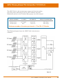
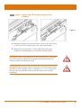
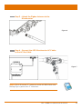
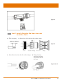
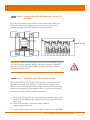
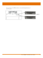
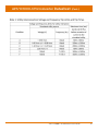
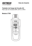
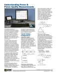
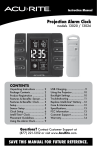
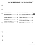
Installation/User Manual
APS YC1000-3
Photovoltaic 3-Phase Grid-connected Microinverter
Version 1.1 2/15
APS America
1015 Hostmark St. Ste 104; Poulsbo, WA 98370
TEL: 206-855-5100
EMAIL: [email protected]
WEB: www.APSamerica.com
© All Rights Reserved
TABLE OF CONTENTS
IMPORTANT SAFETY INSTRUCTIONS
1
Radio interference statement
3
APS YC1000-3 System Introduction
4
APS Three-phase Microinverter YC1000-3
6
APS Microinverter System Installation
7
Additional Installation components from APS
8
Required Parts and Tools
8
Installation Procedures
9
Step 1 - Install the AC Branch Circuit Junction Box
9
Step 2 – Attach the APS Microinverters to the Racking
Step 3 - Attach the Zigbee Antenna to the Microinverter
Step 4 - C
onnect the APS Microinverter AC Cables
to the AC Bus Cable
11
11
Step 5 – Install a Protective End Cap at the end of the
AC Bus Cable
10
12
Step 6 - Connect the APS Microinverters to the PV Modules
13
APS Microinverter System Operating Instructions
15
Troubleshooting
16
Status Indications and Error Reporting
16
Troubleshooting a non-operating APS Microinverter
17
Replace a Microinverter
18
Technical Data
19
Datasheet
20
Wiring Diagram
22
APS YC1000-3-480 Installation/User Manual
iii
IMPORTANT SAFETY INSTRUCTIONS
SAVE THESE INSTRUCTIONS! This manual contains important
instructions to follow during installation and maintenance of the APS
YC1000-3-480 Photovoltaic Grid-connected Inverter (microinverter).
To reduce the risk of electrical shock and ensure the safe installation
and operation of the APS microinverter, the following symbols appear
throughout this document to indicate dangerous conditions and
important safety instructions.
WARNING: This indicates a situation where failure to follow
instructions may cause a serious hardware failure or personnel danger
if not applied appropriately. Use extreme caution when performing
this task.
WARNING
SYMBOL
NOTE: This indicates information that is important for optimized
microinverter operation. Follow these instructions closely.
SAFETY INSTRUCTIONS
NOTE
SYMBOL
✔✔ Do NOT disconnect the PV module from the APS
Microinverter without first disconnecting the AC power.
✔✔ Only qualified professionals should install and/or replace APS
microinverters.
✔✔ Perform all electrical installations in accordance with local
electrical codes.
✔✔ Before installing or using the APS microinverter, please read all
instructions and cautionary markings in the technical documents
and on the APS microinverter system and the PV-array.
✔✔ Be aware that the body of the APS microinverter is the heat sink
and can reach high temperatures. To reduce risk of burns, do not
touch the body of the microinverter.
✔✔ Do NOT attempt to repair the APS microinverter. If it fails, contact
APS Customer Support (206-855-5100) to obtain an RMA number
and start the replacement process. Damaging or opening the APS
microinverter voids the warranty.
✔✔ Do NOT expose the connections to directed, pressurized liquid
(pressure washer, etc.).
APS YC1000-3 Installation/User Manual
1
✔✔ Do NOT expose the connections to continuous immersion.
✔✔ Do NOT over-tension the AC connector (tension due to pulling or
bending the cable near the connector).
✔✔ Use only provided/authorized connectors and cables.
✔✔ Do NOT allow contamination into the connectors.
✔✔ Use an authorized terminator to seal the end of the AC Bus Cable.
Using another sealing method voids the warranty.
✔✔ To reduce the risk of fire, connect only to a circuit provided with
25 amperes maximum branch circuit overcurrent protection – in
accordance with the National Electrical Code (NEC), ANSI/NFPA
70.
✔✔ Both AC and DC voltage source are terminated inside this
equipment. Each circuit must be individually disconnected before
servicing.
✔✔ DC voltage is supplied to this equipment when the photovoltaic
array is exposed to light.
✔✔ This Utility-Interactive Inverter contains active anti-islanding
protection (IEEE1547) and is tested per FCC/IC.
APS YC1000-3 Installation/User Manual
2
Radio Interference Statement
RADIO INTERFERENCE STATEMENT
FCC Compliance: The equipment can comply with the limits for a
class B digital device, pursuant to part 15 of the FCC Rules, which
are designed to protect against harmful interference in a residential
installation. The equipment could radiate radio frequency energy and
this might cause harmful interference to radio communications if not
following the instructions when installing and using the equipment.
But there is no guarantee that interference will not occur in a
particular installation. If this equipment causes harmful interference
to radio or television reception, the following measures might resolve
the issues:
A. R
elocate the receiving antenna and keep it well away from the
equipment
B. C
onsult the dealer or an experienced radio/TV technical for
help
Changes or modifications not expressly approved by the party
responsible for compliance may void the user’s authority to operate the
equipment.
APS YC1000-3 Installation/User Manual
3
APS YC1000-3 System Introduction
The APS microinverter is used in utility-interactive grid-tied
applications, comprised of three (3) key elements:
• APS microinverter
• APS Energy Communication Unit (ECU)
• APS Energy Monitor and Analysis (EMA) web-based
monitoring and analysis system
Figure 1
This integrated system improves safety, maximizes solar energy
harvest, increases system reliability, and simplifies photovoltaic (PV)
system design, installation, maintenance, and management.
APS YC1000-3 Installation/User Manual
4
APS microinverters maximize energy production
Each PV module is operating at the maximum peak power point,
which ensures that the maximum power is exported to the utility grid.
The APS microinverter ensures top performance from the array by
maximizing the performance of the module within the array when PV
modules in the array are affected by shading.
More reliable than centralized or string inverters
The distributed microinverter system ensures that no single point
of system failure exists across the PV system. APS microinverters
are designed to operate at full power at ambient temperatures of
up to +65°C (+149° F). The inverter housing is designed for outdoor
installation and complies with the NEMA 4X environmental enclosure
rating.
Simple to install
You can install individual PV modules in any combination of module
quantity, orientation, type, and power rating.
Smart system performance monitoring and analysis.
The APS Energy Communication Unit (ECU) is installed by simply
plugging it into any wall outlet and providing it with an Ethernet or
Wi-Fi connection to a broadband router. After installing the ECU, the
full network of APS microinverters automatically reports to the APS
Energy Monitor and Analysis (EMA) web server. The EMA software
displays performance trends, informs you of abnormal events, and
controls system shutdown when it is needed. Reference the ECU
Manual for installation and operation instructions.
APS YC1000-3 Installation/User Manual
5
APS Three-phase Microinverter YC1000-3
The APS YC1000-3-480 microinverters connect with the three-phase
grid, and operate with most 60 and 72 cell PV modules. For more
information, please see the Technical Data page (p. xx) of this manual.
MODEL NUMBER
YC1000-3-480
YC1000-3-208
AC GRID
PV MODULE
MODULE CONNECTOR
277V/480V
208V
60,72 Cell 60,72 Cell
MC-4 Type
MC-4 Type
Maximum number of inverters per branch = 11 for 15A X 3 Breaker
The following diagram shows the APS YC1000-3 microinverter
schematic:
Figure 2
APS YC1000-3 Installation/User Manual
6
APS Microinverter System Installation
A PV system using APS Microinverters is simple to install. Each
Microinverter easily mounts on the PV racking, directly beneath the
PV module(s). Low voltage DC wires connect from the PV module
directly to the Microinverter, eliminating the risk of high DC voltage.
Installation MUST comply with local regulations and technical rules.
WARNING: Perform all electrical installations in accordance with
local electrical codes.
NOTE: An AC GFCI device should not be used to protect the
dedicated circuit to the APS microinverter even though it is an outside
circuit. None of the small GFCI devices (5mA-30 mA) are designed for
back feeding and will be damaged if back fed. In a similar manner, AC
AFCIs have not been evaluated for back feeding and may be damaged
if back fed with the output of a PV inverter.
WARNING: Be aware that only qualified professionals should install
and/or replace APS microinverters.
WARNING: Before installing or using an APS microinverter, please
read all instructions and warnings in the technical documents and on
the APS microinverter system itself as well as on the PV array.
WARNING: Be aware that installation of this equipment includes
the risk of electric shock.
WARNING: Do not touch any live parts in the system, including the
PV array, when the system has been connected to the electrical grid.
NOTE: We strongly recommend that you install surge protection
devices in the dedicated meter box.
Installation Procedures
APS YC1000-3 Installation/User Manual
7
Additional Installation components from APS
✹✹ Protective end cap (sold separately)
✹✹ Sealing caps (sold separately)
Required Parts and Tools
✹✹
✹✹
✹✹
✹✹
✹✹
AC connection junction box(s)
Mounting hardware suitable for module racking
Sockets and wrenches for mounting hardware
Phillips screwdriver
Torque wrench
NOTE: The AC output is bonded to ground. The neutral is not. Over-
current protection for the AC output circuit needs to be provided in the
end installation. A disconnect switch needs to be provided for the AC
output circuit (may be required by local code or jurisdiction).
APS YC1000-3 Installation/User Manual
8
APS microinverters are designed to only operate when they can sense
power coming from the grid. Even if they are plugged into the PV array,
they will not turn themselves on until they can read power from the grid.
WARNING: Do NOT connect APS microinverters to the utility grid or
energize the AC circuit until you have completed all of the installation
procedures as described in the following sections.
NOTE: It is best to plug in the ECU and verify Internet connectivity
early in the installation process if you are going to be installing an ECU
to monitor the system. This allows the ECU software to update itself
with the latest firmware.
Step 1 – Install the AC Branch Circuit Junction Box
Figure 3
A. Install an appropriate junction box at a suitable location on the
PV racking system (typically at the end of a branch of modules).
B. Connect the open wire end of the AC bus cable into the junction
box using an appropriate gland or strain relief fitting.
C. Wire the conductors: L1- RED; L2 - BLACK; L3 - ORANGE; N WHITE; PE – GREEN.
D. Connect the AC branch circuit junction box to the point of utility
interconnection.
APS YC1000-3 Installation/User Manual
9
Step 2 – Attach the APS Microinverters to the Racking
Figure 5
A. Mark the location of the microinverter on the rack, with respect
to the PV module junction box or any other obstructions.
B. Mount one microinverter at each of these locations using
hardware recommended by your module racking vendor.
WARNING: Prior to installing any of the microinverters, verify that
the utility voltage at the point of common connection matches the
voltage rating on microinverter label.
WARNING: Do not mount the microinverter in a location that allows
exposure to direct sunlight. Allow a minimum of ¾” (1.5 cm) between
the top of the roof and the bottom of the microinverter for proper
ventilation.
APS YC1000-3 Installation/User Manual
10
Step 3 – Attach the Zigbee Antenna to the
Microinverter
Figure 6
Step 4 - Connect the APS Microinverter AC Cables
to the AC Bus Cable
Figure 7
NOTE: Cover all unused “T” connectors on the AC BUS Cable with
Sealing Caps to protect the “T” connectors.
APS YC1000-3 Installation/User Manual
11
Figure 8
Step 5 - Install a Protective End Cap at the end of
the AC Bus Cable
A. Wire stripping
B. Insert the cable end into the gasket clamp
Figure 9
Nut
Gaske Clamp
C. Insert five wires into the five cable clamps
Seal
Body
D. Rotate the nut
until the latching
mechanism meets
the base
Figure 10 & 11
APS YC1000-3 Installation/User Manual
12
Step 6 - Connect the APS Microinverters to the PV Modules
Place the PV modules into position on the racking and connect the
DC input cables to the microinverters based on optimum layout
configuration (up to four PV modules per microinverter).
Figure 12 & 13
WARNING: Double check to make sure all of the AC and DC wiring
has been correctly installed. Ensure that none of the AC and/or DC
wires are pinched or damaged. Make sure that all of the junction
boxes are properly closed.
Step 7 - Complete the APS Installation Map
Fill in the APS Warranty Cards, which provide system information
and the installation map. Feel free to provide your own layout if a
larger or more intricate installation map is required. The layout map
provided is designed to accommodate labels in vertical or horizontal
orientation to meet all the field PV connections.
1. E
ach APS microinverter has removable serial number labels. Peel
a label off, and affix it to the respective location on the APS installation map.
2. F
ill out the warranty cards and email to APS at
[email protected].
3. R
egister the system using your Installer Account on the APS EMA.
APS YC1000-3 Installation/User Manual
13
You can then use the EMA website to view detailed performance of
the PV system.
Figure 14
APS YC1000-3 Installation/User Manual
14
APS Microinverter System Operating Instructions
To operate the APS microinverter PV system:
1. Turn ON the AC circuit breaker on each microinverter branch
circuit.
2.Turn ON the main utility-grid AC circuit breaker. Your system
will start producing power after a five-minute safety delay
period.
NOTE: The status LED for on each microinverter will blink green
three (3) times to indicate normal operation once DC power is applied.
It is important to understand that this “start up” sequence occurs once
the first module is connected to the microinvert and is successfully
generating DC power. The “start up” sequence does NOT reoccur as
additional modules are connected to the same microinverter.
3.The APS microinverters will start to send performance data
to the ECU. The time required for all the microinverters in
the system to report to the ECU will vary depending on the
number and configuration of microinverters in the system. You
can verify proper operation of the APS Microinverters via the
ECU. See the ECU Installation and Operation Manual for more
information.
APS YC1000-3 Installation/User Manual
15
Troubleshooting
Qualified personnel can use the following troubleshooting steps if the
PV system does not operate correctly:
Status Indications and Error Reporting
START UP LED
T
hree (3) short green blinks, when DC power is first applied
to the microinverter, indicates a successful microinverter
start up. It is important to understand that this “start up”
sequence occurs once the first module is connected to the
microinvert and is successfully generating DC power. The
“start up” sequence does NOT reoccur as additional modules
are connected to the same microinverter.
OPERATING LED
Flashing Slow Green (10 sec. gap) – P
roducing power and
communicating with
ECU
Flashing Fast Green (2 sec. gap) – Producing power and
not communicating with
ECU
Flashing Red – Not producing power
Other Faults
A
ll other faults are reported to the ECU. Refer to the ECU
Installation and Operation Manual for a list of additional
faults and troubleshooting procedures.
WARNING: Only qualified personnel should troubleshoot the APS
microinverter.
WARNING: Never disconnect the DC wire connectors under
load. Ensure that no current is flowing in the DC wires prior to
disconnecting. An opaque covering may be used to cover the module
prior to disconnecting the module.
WARNING: Always disconnect AC power before disconnecting the
PV module wires from the APS microinverter. The AC connector of the
first microinverter in a branch circuit is suitable as a disconnecting
means once the AC branch circuit breaker in the load center has been
opened.
APS YC1000-3 Installation/User Manual
16
WARNING: The APS microinverter is powered by PV module DC
power. Make sure you disconnect and reconnect the DC connections to
watch for the three short LED flashes indicating start up.
Troubleshooting a non-operating APS microinverter
To troubleshoot a non-operating APS microinverter, follow the steps
below in order:
1. V
erify the utility voltage and frequency are within ranges
shown in the Technical Data of this manual.
2. Check the connection to the utility grid. Verify utility power
is present at the inverter in question by removing AC, then
DC power. Never disconnect the DC wires while the
microinverter is producing power. Re-connect the DC
module connectors and watch for three short LED flashes.
3. Check the AC branch circuit interconnection between all the
microinverters. Verify that the inverters are energized by the
utility grid as described in the previous step.
4. M
ake sure that any AC breaker are functioning properly and
are closed.
5.Check the DC connections between the microinverter and the
PV module.
6.Verify the PV module DC voltage is within the allowable range
shown in the Technical Data of this manual.
7.If the problem persists, please call APS Technical Support at
(206) 855-5100 (Option #2).
WARNING: Do not attempt to repair the APS microinverter. If
troubleshooting methods fail, return the microinverter to your
distributor for replacement.
APS YC1000-3 Installation/User Manual
17
Qualified personnel can use the following troubleshooting steps if the
PV system does not operate correctly:
Replace an APS Microinverter
Follow the following procedure to replace a failed APS microinverter:
1. R
emove the APS microinverter from the PV Module, in the
following order:
a. Disconnect the AC by opening the branch circuit breaker.
b. Cover the module with an opaque cover.
c. Disconnect the first AC connector in the branch circuit.
d. D
isconnect the PV module DC wire connectors from the
microinverter.
e. Remove the microinverter from the PV array racking.
2. Install a replacement microinverter to the rack.
3.Connect the AC cable of the replacement microinverter and
the neighboring microinverters to complete the branch circuit
connections.
4.Close the branch circuit breaker, and verify operation of the
replacement microinverter.
APS YC1000-3 Installation/User Manual
18
TECHNICAL DATA
WARNING: Be sure to verify the voltage and current specifications
of your PV module match with those of the microinverter.
WARNING: You must match the DC operating voltage range of
WARNING: The maximum open circuit voltage of the PV module
the PV module with the allowable input voltage range of the APS
microinverter.
must not exceed the specified maximum input voltage of the APS
microinverter.
APS YC1000-3 Installation/User Manual
19
APS YC1000-3 Microinverter Datasheet
INPUT DATA (DC)
Recommended PV Module Power Range (STC) Up to 310W (4 Module Configuration)
Up to 360W (3 Module Configuration)
MPPT Voltage Range 16-55V
Maximum Input Voltage 60V
Maximum Input Current 14.8A x 4
Startup Voltage 22V
OUTPUT DATA (AC)
277/480V
208V
Maximum Output Power 900W
900W
3-Phase Grid Type 277V/480V
208V
Nominal Output Current 1.08Ax3 2.50Ax3
Nominal Output Voltage 277Vx3
Nominal Output Frequency 60Hz /59.3-60.5Hz
120Vx3
*
60Hz /59.3-60.5Hz*
Power Factor >0.99
>0.99
Total Harmonic Distortion <3%
<3%
Maximum Units per Branch 11 for 15Ax3 Breaker
11 for 15Ax3 Breaker
EFFICIENCY
Peak efficiency 95%
CEC Weighted Efficiency 94.5%
Nominal MPPT efficiency 99.9%
MECHANICAL DATA
Operating Ambient temperature range -40°F to +149°F (-40°C to +65°C)
Operating Internal temperature range -40°F to +185°F (-40oC to +85°C)
Storage Temperature Range -40°F to +185°F (-40oC to +85°C)
Dimensions (W x H x D) inches 10.2” X 9.5” X 1.4”
Dimensions (W x H x D) mm 259mm X 242mm X 36mm
AC Bus Cable 14AWG
Weight 8.4lbs/3.8kg
Enclosure rating NEMA 4X
Cooling Natural Convection
FEATURES
Communication ZigBee wireless
Integrated Ground Fault Protection (GFP)
The DC circuit meets the requirements for
ungrounded PV arrays in NEC690.35. No
additional ground is required. Ground fault
protection (GFP) is integrated into microinverter.
Emissions & Immunity (EMC) Compliance FCC Part15; ANSI C63.4; ICES-003
Safety Class Compliance UL1741xCSA C22.2 No.107.1-01
Grid Connection Compliance IEEE1547
Warranty
10 years standard, extendable to 25 years
* Programmable per customer and utility requirements. All settings UL approved
Specifications subject to change without notice – please ensure you are using the most recent update found at www.APSamerica.com
2.9.15 © All Rights Reserved
APS YC1000-3 Installation/User Manual
20
APS YC1000-3 Microinverter Datasheet
(Cont.)
APS YC1000-3 Installation/User Manual
21
Wiring Diagram
Figure 15
APS YC1000-3 Installation/User Manual
22