1
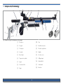
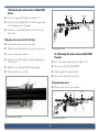
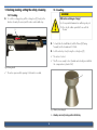
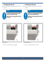
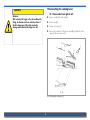
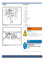
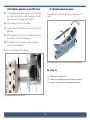
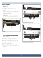
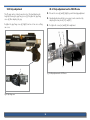
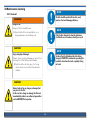
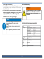
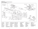
User Manual
8001 / 8002 S2 / 9003 Premium S2 Series Models
Issue 09/2009
Contents
1 Components/Terminology........................... 4
12 Removing the aluminium stock (depending
on model) ................................................. 13
2 Introduction ................................................ 5
12.1 Removing the aluminium stock on Model 8002... 13
12.2 Removing the action carrier on 9003 Precise 14
12.3 Removing the action carrier on 9003 Premium. 14
3 Key to Symbols ........................................... 5
3.1
3.2
General instructions ..................................... 5
Safety instructions ......................................... 5
13 Cocking, loading, setting the safety, releasing 15
13.1
13.2
13.3
13.4
4 General handling of firearms .................... 6
4.1
4.2
4.3
4.4
4.5
4.6
Important basics ........................................... 6
Shooting ........................................................ 7
Maintenance ................................................. 8
Transport ....................................................... 8
Storage.......................................................... 8
Hearing and eye protection .......................... 8
Cocking ....................................................... 15
Loading ....................................................... 15
Engaging the safety catch ........................... 16
Releasing the safety catch .......................... 16
14 Converting the cocking lever.................... 17
14.1 Conversion from right to left....................... 17
15 Trigger ...................................................... 18
5 General handling of compressed air cylinders ...8
15.1
15.2
15.3
15.4
15.5
15.6
15.7
Trigger weight ............................................. 19
First stage pull (only with two-stage trigger)19
Sear engagement ....................................... 19
First stage travel (only with two-stage trigger) 19
Trigger stop ................................................. 20
Adjusting the trigger blade ........................ 20
Conversion from two-stage trigger to single
stage trigger ................................................. 20
15.8 Conversion from single stage trigger to twostage trigger ....................................................... 20
15.9 Trigger faults caused by incorrect adjustment .....21
15.10 Basic trigger adjustment ............................ 21
6 Safety flag................................................. 10
7 Legal ......................................................... 11
8 Intended use ............................................. 11
9 Liability ..................................................... 11
10 Before using for the first time .................. 12
11 Soft-Link ® (only Model 9003 Premium) .. 12
16 Dry firing device ....................................... 22
2
22 Maintenance/cleaning.............................. 30
17 Compressed air cylinder ........................... 22
22.1
22.2
22.3
22.4
17.1 Screwing the compressed air cylinder in .... 23
17.2 Releasing the compressed air cylinder ....... 23
17.3 Filling the compressed air cylinder............. 23
18 Cheek piece .............................................. 24
General ....................................................... 30
Maintenance intervals ................................ 31
Trigger maintenance .................................. 32
Maintenance of the optical sights ............... 32
23 Troubleshooting ........................................ 32
18.1 Removing the cheek piece .......................... 24
18.2 Adjusting the cheek piece ........................... 24
18.2.1 Setting the cheek piece 9003 Precise ....... 25
24 Technical data........................................... 32
25 Disposal .................................................... 33
19 Buttplate ................................................... 25
19.1 Removing the buttplate .............................. 25
19.2 Adjusting the buttplate (model-dependent) 25
19.2.1 Buttplate adjustment 9003 Precise ........... 26
19.3 Buttplate adjustment options ..................... 26
26 Miscellaneous ........................................... 33
27 Guarantee ................................................ 34
20 Stock adjustment ...................................... 27
20.1 Forend ......................................................... 27
20.1.1 Forend raiser block adjustment 4960 ...... 27
20.2 Grip adjustment .......................................... 28
20.2.1 Grip adjustment 9003 Precise .................. 28
20.2.2 PRO-Grip equipment (model-dependent) . 29
21 Optical sights/rear sight (option) ............. 29
21.1 Mounting ..................................................... 29
21.2 Elevation and windage adjustment ............ 29
21.3 Zero adjustment.......................................... 29
3
1 Components/Terminology
[1]
[2]
[16]
[3]
[9]
[18]
[8]
[4]
[7]
[6]
[13]
[12]
[11]
[10]
Fig. 1 Overall view using 8002 with aluminium stock as example
[1]
Cheek piece
[10]
Grip
[2]
Rear sight
[11]
Barrelled action carrier
[3]
Cocking lever
[12]
Thread for weight carrier
[4]
Front sight
[13]
Buttplate
[5]
Barrel weight
[14]
Air release screw
[6]
Compressed air cylinder
[15]
Refilling adapter
[7]
Support
[16]
High sight block
[8]
Forend raiser block
[17]
Visible muzzle
[9]
Trigger
[18]
Barrel unit
4
[5]
[17]
[14]
[15]
2 Introduction
3 Key to Symbols
Dear ANSCHÜTZ Customer,
In this handbook, the following symbols are used to distinguish between
general information and particularly important information:
Thank you for choosing an ANSCHÜTZ product. Many spectacular
sporting successes have been achieved by marksmen, olympians and
shooters in world and European championships using ANSCHÜTZ
sporting rifles.
ANSCHÜTZ hunting and sporting rifles are highly reputed as a result
of their well-engineered design, workmanship and outstanding shooting
performance. Quality and precision are a part of our tradition, and
have grown as a result of our experience since 1856.
3.1
General instructions
X
is the symbol for an instruction
9
shows the desired result
y
is the symbol for a list item
) is the symbol for a possible handling consequence
3.2
We manufacture the famous ANSCHÜTZ small-bore match rifles,
match air rifles and match air pistols; small-bore biathlon rifles; hunting
and closed season rifles of various calibres; single-shot and repeaters;
Flobert rifles, and also silhouette rifles and "varmint" guns.
Safety instructions
$ identifies a safety instruction
NOTE!
An instruction indicating a specific course of action.
We wish you much pleasure and sporting success with your new
ANSCHÜTZ product.
Your ANSCHÜTZ team
CAuTION!
Indicates a hazardous situation that can lead to
minor physical injury or material damage.
WARNING!
Indicates a hazardous situation that can lead to
serious physical injury or death.
5
4 General handling of firearms
$ A firearm must only ever be used for its designated purpose.
$ Firearms owners are responsible for ensuring that their firearm is at no time, and especially when absent, within reach of or accessible to children or other unauthorised persons.
Firearms are dangerous objects requiring the utmost care in their storage and use. The following safety and warning instructions must be
observed without exception!
$ Firearms must not be handed over to unauthorised persons.
$ Modifications to the rifle and the use of non-genuine ANSCHÜTZ accessories can lead to
malfunctions.
NOTE!
$ Serious or life-threatening injuries and damage can be caused by the use of incorrect ammunition, by contamination in the barrel or by incorrect cylinder components.
The firearms legislation of the relevant country must
be respected and complied with.
4.1
$ Weapons modified in a way that could affect safety must not be used. If a fault or malfunction is detected, the weapon must be unloaded and taken to an authorised gunsmith
for repair.
Important basics
$ In the event of external effects (e.g. corrosion, being dropped, etc.), the weapon must be
checked by an authorised gunsmith.
NOTE!
The use of firearms while under the influence of
drugs, alcohol or medication is not permitted.
Vision, dexterity and judgement can all be adversely
affected.
A good physical and mental constitution is a prerequisite for using a firearm.
$ A weapon must always be treated with the utmost care and be protected from accidental
damage.
6
4.2
Shooting
$ Any firearm must be treated as if it were loaded.
$ Never pick up a firearm by the trigger.
WARNING!
$ Shooting galleries must be adequately ventilated.
Danger to life and causing material damage!
$ Any bullet trap in the shooting gallery must be completely safe and visible.
Aiming the rifle at people and objects.
h When the rifle is not in use, keep the muzzle pointing in a safe direction.
h The muzzle of a firearm must never be held in
a direction where it can can cause damage or
endanger life.
$ No persons may stand in the vicinity of the target during a shoot.
$ Firearms should not be used when visibility is poor.
$ Do not shoot into the air, at hard or smooth surfaces, at water or at targets on the horizon.
$ Do not shoot at targets if the shot could ricochet or be deflected in a dangerous manner.
$ To prevent accidents or damage to your rifle, never discharge a shot with the muzzle held
under water or up against materials or objects.
$ Only shoot using the calibre specified on the barrel of the rifle.
$ Only new, clean, factory-charged ammunition of the calibre permitted for the rifle may be
used.
$ The ammunition must conform to the specifications of the C.I.P.
$ Only ever load the rifle immediately before use.
WARNING!
$ Life-threatening injuries and material damage can be caused by the use of incorrect ammunition, contamination in the barrel or incorrect cylinder components.
Malfunction when shooting!
$ Only genuine ANSCHÜTZ parts may be used.
Shot not discharged after trigger pulled.
h Do not look down into the muzzle.
h Keep the muzzle of the firearm pointing in a safe
direction.
h Unload the firearm.
h Remove residues from the barrel.
7
4.3
5 General handling of compressed air cylinders
Maintenance
$ Ensure that the rifle is unloaded before and after use or during maintenance and cleaning.
4.4
NOTE!
Transport
$ Firearms may only be transported in an unloaded condition and in locked containers.
When using compressed air cartridges please always observe the manufacturer's instructions!
$ Only transport firearms in a clean, dry condition.
4.5
Storage
$ Firearms that are not in use must be kept in a secure place under lock and key.
$ The fill level indicator of the compressed air cylinder may only be checked when the
compressed air rifle is unloaded and uncocked.
$ Firearms must always be stored in an unloaded and uncocked condition.
$ Ammunition must be kept in a separate place under lock and key.
4.6
$ The fill level indicator of the compressed air cylinder must not be checked during re-filling.
Hearing and eye protection
NOTE!
NOTE!
Design aspects mean that the fill level indicator operates with an accuracy of ± 10%. Temperature influences mean that there can also be deviations in the
fill level indicator.
For your own safety, approved hearing and eye protection should be used when shooting!
Shooting without safety equipment can result in damage to your hearing and sight.
$ Full compressed air cylinders must not be exposed to temperatures below -20°C or above
70°C (when transporting and storing them, adequate insulation must be provided, e.g. by
storing in expanded polystyrene packaging or in a gun case).
$ In aircraft, when sending by post, etc. the compressed air cylinders must always be
unfilled.
$ After approx. 20 fillings, the compressed air cylinder must be emptied slowly and completely in order to allow any condensed water to escape.
8
NOTE!
NOTE!
ANSCHÜTZ recommends the use of an air release
screw from the ANSCHÜTZ range of accessories
(order No. 711.3408) for emptying the compressed
air cylinder.
Self monitoring!
The marksman is responsible for compliance with
the regulations and stipulations contained in the
ANSCHÜTZ user's handbook.
ANSCHÜTZ accepts no liability for damage of any
kind caused by modification of parts, conversion or
fitting of non-genuine ANSCHÜTZ parts or by noncompliance with the user's manual.
$ The compressed air cylinder must be checked for cracks and damage before each use.
$ Compressed air cylinders which have leaks or which are damaged must be emptied safely
and must not be used or filled again.
$ Compressed air cylinders must not be used for longer than 10 years.
$ After 10 years (from the date of manufacture) the compressed air cylinders must be safely
emptied in accordance with the manual (see Chapter 17) and must not be used or filled
any more (the date of manufacture is marked on the compressed air cylinder).
WARNING!
$ The surface of the compressed air cylinder must not be tampered with.
Danger of explosion!
$ In particular, you must not carry out any engraving or other abrasive processes because
this could lead to damage to the pressurised container and thus present a safety hazard.
Explosion danger from oiled air entry valve and
thread.
h The air entry valve and thread on the compressed
air cylinder should only be lightly greased
using genuine ANSCHÜTZ grease (special grease
4425, Order No. 001489).
$ Compressed air cylinders and the refilling adapter must be stored in a secure, dry, greasefree and dust-free location.
NOTE!
The refilling adapter is also fitted with an air filter to
protect from dirt and dust particles.
$ After unscrewing the compressed air cylinder, the cylinder thread must be kept clean and
the relevant protective cap must be fitted.
9
6 Safety flag
$ The maximum filling pressure for compressed air cylinders is 200 bar at room temperature.
WARNING!
Danger of explosion!
Overfilled compressed air cylinder.
h The maximum filling pressure of 200 bar at room
temperature must not be exceeded.
$ When filling the compressed air cylinder, the compressed air must not contain oil, water or
any other contaminant (DIN EN 12021 - breathing air).
$ ANSCHÜTZ supplies compressed air cylinders unfilled, in accordance with the safety regulations.
CAuTION!
$ Compressed air cylinders must never be opened or modified mechanically by
non-authorised specialists.
Malfunction and missing action pressure!
$ The compressed air cylinder must be protected from forceful impacts.
Bent loading mechanism caused by incorrect handling.
h Never close the action if the safety flag is inserted.
$ Compressed air cylinders are not intended for the transport of gases of any kind.
NOTE!
When filling (amongst other things, also for commercial purposes) the regulations of the "Technical Regulations for Compressed Gases (TRG)" or the legal
regulations of the specific country must be complied
with.
10
7 Legal
9 Liability
ANSCHÜTZ will accept no liability or claims for compensation for
NOTE!
damage of any kind arising from:
The applicable firearms legislation, regulations and
provisions for the relevant country, and also the
safety rules of the hunting and sporting organisations
must be observed.
y
y
y
y
y
y
y
y
8 Intended use
failure to comply with the instructions in this user's handbook,
improper treatment or repair,
use of non-genuine ANSCHÜTZ parts,
incorrect handling or care,
negligence,
removal of the sealing lacquer,
unauthorised tampering or
transport damage.
.
The ANSCHÜTZ compressed air 8001, 8002 and 9003 Premium are
compressed air rifles. They are exclusively for use on ranges (for sports
disciplines) and must be used exclusively by persons with the relevant
firearms permit.
CAuTION!
Modifications to or tampering with the rifle or its
parts are forbidden and may possibly infringe the
guarantee conditions.
Alterations of this kind can have an adverse effect on
the safe use of the product and lead to accidents that
endanger life and limb. In such cases the guarantee
is automatically void.
The use is subject exclusively to the "General Technical Regulations“
for all shooting sports disciplines of the INTERNATIONAL SHOOTING
SPORT FEDERATION (ISSF), Bavariaring 21, 80336 München, Germany
or the regulations of the INTERNATIONAL BIATHLON UNION,
Peregrinstrasse 14, A-5020 Salzburg, Austria, E-Mail: [email protected].
NOTE!
A firearm must only ever be used for its designated
purpose.
$ The rifle must be examined for any changes each time before use.
11
10 Before using for the first time
11 Soft-Link ® (Model 9003 Premium only)
NOTE!
The air rifle and the action carrier are connected together with the SoftLink® connection system. This action fixing has a vibration-damping
fixed mount (in the area of the action housing) and a vibration-damping
free mount (on the support).
For safety reasons, check the action fixing each time
before you shoot.
X
Wipe off any excess oil from the surface of the barrelled action.
X
Cleaning cord with cotton wicks (Cleaning Kit 507, Order
No. 001491) to be pulled through the barrel from the chamber
towards the muzzle.
Tensions that are created as a result of different materials in air rifle
actions and action carriers, and their different coefficients of thermal
expansion, are thus eliminated (tension-compensating thermal expansion
joint).
The integrated Soft-Link® vibration dampers also de-couple the air rifle
action and the action carrier. The oscillations and vibration created in
the air rifle action are effectively absorbed and cannot be felt in the
aluminium stock by the marksman.
The airgun is delivered with hard Soft-Link® vibration damping. The
scope of delivery includes soft Soft-Link® vibration damping.
Changing the vibration damping is carried out as follows:
X Release screws [1] on both sides.
X
Release the set screws [2] on both sides (approx. 4 turns).
X
Pull the support [3] off the action carrier towards the muzzle.
X
Remove the action [4] from the action carrier [5].
Fixing to the barrelled action carrier:
X Insert or replace the round (hard or soft) Soft-Link® elements [C] on
both sides.
12
12 Removing the aluminium stock
(model-dependent)
Fixing to the support:
X Insert or replace the long (hard or soft) Soft-Link® elements [A] on
both sides (2 in number).
X
12.1 Removing the aluminium stock on model 8002
Fitting the action is carried out in reverse order.
NOTE!
When using the soft Soft-Link® elements, before
fitting the screws, the flanged bushes [B] must be
fitted from the outside into the Soft-Link® chamber
at position [1].Then the screws must be fitted and
tightened on both sides at position [1].
X
Remove the compressed air cylinder (see Chapter 17.2).
X
Remove the screws [a] on the end of the support [5].
X
Release the screws [b] on the support fixing.
X
Remove the bedding screws [c] on the forend [6].
X
Remove the forend [6].
X
Remove the bedding screw [d] in the aluminium stock (in front of
the trigger).
X
Pull the support [5] from the aluminium stock until the mechanical
connection releases.
X
Remove aluminium stock from action (the vibration-absorbing elastomer in the action bed is now loose).
X
Fitting is carried out in the reverse sequence.
[4]
[3]
[1]
[5]
[b]
[2]
[B]
[A]
[A]
[5]
[C]
[d]
[B]
[c]
[C]
Fig. 2 Soft-Link®
Fig. 3 Removing the aluminium stock
13
[6]
[c]
[a]
12.2 Removing the action carrier on Model 9003
Precise
X
Remove the compressed air cylinder (see Chapter 17.2).
X
Remove the screws [3a] and [3b] on the end of the support and
remove the upper section of the support.
X
Release the screws [1a] and [1b] at the side, then remove the
action carrier.
[1a]/[1b]
[2a]/[2b]
[3a]/[3b]
Fitting the action carrier (for the first time)
X
Place the action carrier in position on the action.
X
Tighten the screws [1a] and [1b] at the side of the action carrier.
X
Screw the compressed air cylinder in
X
Tighten the screws [2a] and [2b], ensuring the clamping piece is
not under tension.
X
Remove the compressed air cylinder (see Chapter 17.2).
X
Tighten the screws [3a] and [3b] after fitting the support.
X
Release screws [1a], [1b], [2a] and [2b].
X
Make sure that the screws are tight.
X
Slide the support [3] towards the muzzle.
X
Remove action carrier [5] from action [4].
[2]
Fig. 3b Model 9003 Precise
12.3 Removing the action carrier on Model 9003
Premium
[3]
Fitting the action carrier
X
Fitting is carried out in the reverse sequence.
[1a]/[1b]
[4]
[2a]/[2b]
[3]
[2]
[5]
Fig. 3a Removing the action carrier
Fig. 3c Model 9003 Premium
14
[3]
13 Cocking, loading, setting the safety, releasing
13.2 Loading
CAuTION!
13.1 Cocking
X
To cock the cocking piston, pull the cocking lever [2] slowly (in the
direction shown by the arrow) until it reaches a detectable stop.
Malfunction and danger of injury!
Use of non-permitted ammunition and foreign objects.
h Use only the calibre permitted for use with the
firearm.
[2]
Fig. 4 Cocking the rifle
9
X
To load, slide the lead Diabolo (with the flat end [A] facing
forwards) into the chamber until it is flush.
X
Lock the action by slowly closing the cocking lever [2].
9
The action is locked.
9
The rifle is now ready to shoot (loaded and cocked) (provided that
the compressed air cylinder is full).
The action opens and the opening to the barrel is revealed.
[A]
Fig. 5 Diabolo (shown enlarged)
$ Unloading is carried out by shooting a pellet into the bullet trap.
15
13.3 Engaging the safety catch
X
13.4 Releasing the safety catch
Push the safety catch [x] in backwards (in the direction of the arrow,
towards "S").
X
NOTE!
Push the safety catch [x] in forwards (in the direction of the arrow,
towards "F").
NOTE!
The safety catch must engage exactly and audibly
and must not sit between the end stops.
The firearm can only be engaged/released when the
rifle is cocked.
The safety catch must engage exactly and audibly
and must not sit between the end stops.
The firearm can only be engaged/released when the
rifle is cocked.
[x]
[x]
Fig.6 Safety catch "Safe"
9
Fig.7 Safety catch "Ready to Fire"
The rifle is cocked and the safety catch is engaged.
9
16
The rifle is cocked and the safety catch is released.
14 Converting the cocking lever
CAuTION!
14.1 Conversion from right to left
Attention!
After actuating the trigger in the safe condition (dry
firing), the firearm must be re-cocked to release it.
Forcible changeover of the safety can lead to
damage and inadvertent discharge of a shot.
X
Remove circlip [a] from the pin [b].
X
Remove pin [b].
X
Release set screws [c].
X
Remove the complete cocking lever assembly [d] and re-fit on the
opposite side in reverse order.
[b]
[c]
[a]
[d]
[2]
Fig. 8 Converting the cocking lever [2]
17
15 Trigger
Key (to Figs. 9+10)
[2]
1
Tension spring
[3]
2
Catch link
[4]
3
Viewing window
4
Release catch
5
Trigger housing
6
Trigger blade
7
Trigger sear
8
Trigger sear clamping screw
F1
Weight of first stage
F2
Trigger weight
T
Trigger stop
L
First stage travel
C
Basic factory setting/sealed
[1]
[1]
[T]
[7]
[L]
[5]
[6]
Fig. 9 Trigger (side view)
WARNING!
Danger to life!
Danger to life from loaded firearm.
h Make sure that the rifle is unloaded when carrying
out alignment and adjustment procedures.
[8]
NOTE!
The trigger on Model 5065 is delivered with the
following factory setting:
Two-stage trigger with approx. 100 g set trigger
weight.
Fig. 10 Trigger (view from below)
18
WARNING!
NOTE!
The setting screws B and C are pre-set and sealed
in the factory. Setting or modification using these
screws is prohibited.
Danger to life!
Unintentional discharge as a result of too short a sear
engagement and/or too low a trigger weight.
h Do not set the sear engagement too short.
h Do not set the trigger weight too low.
h Do not subject loaded and unsecured rifles to
impact and do not use force to close the breech.
15.1 Trigger weight
Setting the trigger weight using the setting screw F2 (setting range from
50 g to 170 g):
y turn clockwise = trigger weight is increased (+)
y turn anticlockwise = trigger weight is reduced (-)
15.4 First stage travel (only with two-stage trigger)
15.2 First stage pull (only with two-stage trigger)
First stage travel denotes the travel of the trigger blade from the zero
position to the second stage.
Setting the first stage pull using the setting screw F1:
y turn clockwise = first stage weight is increased (+)
y turn anticlockwise = first stage weight is reduced (-)
Setting the first stage travel using setting screw [L]:
y turn clockwise = first stage travel is shortened
y turn anticlockwise = first stage travel is lengthened
15.3 Sear engagement
The sear engagement denotes the travel from the second stage to the
release of the trigger. The sear engagement is set in the factory to an
optimum value.
19
15.5 Trigger stop
15.7 Conversion from two-stage trigger to single
stage trigger
The trigger stop denotes the travel from the second stage to the end
stop for the trigger blade.
Adjustment using setting screw L. Turn the setting screw L to the right until
there is no more first stage travel.
Setting the trigger stop using the trigger stop setting screw [T]:
y turn clockwise = trigger stop is shortened
y turn anticlockwise = trigger stop is lengthened
WARNING!
Danger of injury by automatic firing!
CAuTION!
Automatic firing and malfunction caused by minimum
setting of trigger weight, first stage travel too small or
the sear engagement is too small.
h Do not set the trigger weight too low.
h Do not set the first stage travel and sear engagement too small.
Malfunction!
Trigger stop setting screw is screwed in beyond the
second stage or direct function (trigger will not actuate).
h Trigger stop adjustment screw should not be
screwed in beyond the second stage or direct
function.
15.8 Conversion from single stage trigger to twostage trigger
15.6 Adjusting the trigger blade
Adjustment using setting screw L. Turn the setting screw L to the left until
the desired first stage travel is reached.
Release the relevant clamping screw (according to required setting). The
trigger blade can be moved along the guide, swung to the side and
adjusted in height.
The trigger blade can be removed completely and turned through
180°. The longer part of the trigger blade now points downwards.
The blade holder is asymmetric and can be fitted offset by 180° to
provide additional length adjustment. The lateral blade adjustment can
also be varied in the same way. By releasing the screw (8), the trigger
sear can be turned through 180° to permit offset to the side.
20
15.9 Trigger faults caused by incorrect adjustment
15.10 Basic adjustment of the trigger
The trigger catches the cocking piston or the firing pin, but
does not shoot when the trigger is actuated:
X
NOTE!
This procedure is used to reset all settings on the
trigger. With this starting setting, the trigger can
then be individually adjusted again.
Make sure that the safety catch is released.
) If the trigger stop setting screw [T] is screwed in too far by a few
turns:
X
Screw the trigger stop setting screw [T] to the left by a few turns
until the cocking piston or the firing pin actuates again when the
trigger is actuated.
The trigger does not catch the cocking piston or firing pin:
The setting screw [L] (first stage) is screwed in too far by a few turns.
X Screw the setting screw [L] to the left by a few turns, until the trigger
catches the cocking lever or the firing pin again.
X
Then set the desired first stage travel.
X
Check that the tension spring [1] is undamaged and is hooked in
correctly.
Setting screw [C], sear engagement, has been turned:
X Turn the setting screw [C] by approx. 1 turn to the left.
X
Cock the weapon, turn the screw [C] to the right until the weapon
discharges. Then turn back by 1/5 of a turn.
NOTE!
The trigger function must be checked after every
change. When the fault is eliminated, check the
desired trigger values and reset them if necessary.
21
X
Remove the action from the stock.
X
Set the adjusting screw [T] so that the head of the screw is flush
with the trigger housing surface [5].
X
Set the adjusting screw [L] so that the trigger sear [7] is horizontal.
X
Cock the action.
X
Set the trigger using the relevant adjustment screws to give the
individual settings desired.
16 Dry firing device
17 Compressed air cylinder
The safety catch can also be used as a dry firing device.
X Open the cocking lever and swing it slowly to the rear until a stop
is felt.
The compressed air rifle is fitted with an exchangeable compressed air
cylinder [4]. The compressed air cylinder [4] can be exchanged in both
the full and empty condition. On delivery, the compressed air cylinder
[4] is not screwed in tightly. You should always use the covering cap
to protect the thread on the compressed air cylinder [4] from dust and
damage.
X
Push the safety catch in to "S".
9
Dry firing device is active.
X
Close the cocking lever.
X
Release the trigger.
CAuTION!
Only genuine ANSCHÜTZ compressed air cylinders
(max. 200 bar) may be used!
NOTE!
NOTE!
The safety/dry firing device can only be actuated
when the airgun is cocked.
Repairs to compressed air cylinders may only be
carried out by the manufacturer using genuine replacement parts.
If this is not observed, the liability and guarantee
become void.
17.1 Screwing the compressed air cylinder in
X
Fill the compressed air cylinder before using.
X
Screw the compressed air cylinder slowly and carefully, hand-tight,
into the thread on the sub-assembly carrier (to avoid
damage).
$ A perceptible resistance is felt shortly before the stop, and the valve opens automatically.
22
X
17.3 Filling the compressed air cylinder
Screw the compressed air cylinder in, hand-tight, by approx. one
more turn so that it rests tightly against the stop.
WARNING!
17.2 Releasing the compressed air cylinder
Only refilling bottles with a maximum pressure of
200 bar may be used!
NOTE!
Only oil- and water-free compressed air may be
used (DIN EN 12021)!
ANSCHÜTZ recommends that the compressed air cylinders always be released when the compressed air
rifle is not being used to protect the housing, valve,
seals, springs and for safety reasons (no readiness
to fire if there is no compressed air).
Filling of the compressed air cylinders may only be
carried out using the genuine ANSCHÜTZ refilling
adapter (order No. 711.3409)!
ANSCHÜTZ recommends the use of diving bottles for
refilling the compressed air cylinders.
X
Unscrew the compressed air cylinder by approx. just one turn. Turn
only so far that no air comes out.
X
Cock the rifle (see Chapter 12.1) and release the trigger. Repeat
the procedure 3 times (to allow any remaining air to escape).
NOTE!
) The compressed air cylinder can then be unscrewed with no pressure on the O-ring.
A complete fill (max. 200 bar) is adequate for approx.
200 shots (residual pressure approx. 65 bar).*
Compressed air bottles can be obtained from firearms dealers. Refilling of compressed air bottles can
also be carried out at firearms dealers or in special
stores for diving equipment.
CAuTION!
Material damage!
Damage to the O-ring if the air pressure is too high.
h Never unscrew the compressed air cylinder so far
that the compressed air can be heard coming out.
*Not applicable with Junior cylinder.
23
X
Check all components that are associated with the filling procedure
(refilling bottle, refilling adapter, compressed air cylinder) for
damage.
X
Screw the refilling adapter on to the refilling bottle.
Screw the compressed air cylinder completely on to the refilling
adapter.
18 Cheek piece
X
Tighten the knurled screw on the refilling adapter so that no air can
escape.
X
Release the clamping screw [a].
X
Open the bottle valve very slowly until you can no longer hear a
flowing noise.
X
Remove the cheek piece [1] from the holder.
X
Fit in reverse order.
X
Close the refilling bottle valve again after approx. 5 seconds filling
time (the compressed air cylinder will heat up slightly).
X
X
Vent the refilling adapter by releasing the knurled screw.
X
Screw the knurled screw on the refilling adapter back in.
X
Unscrew the compressed air cylinder and screw it into the rifle by
hand.
18.1 Removing the cheek piece
18.2 Adjusting the cheek piece
The cheek piece can be tilted to various positions. The knurled screws
and the fixing screws [c] and [d] must be released for setting the
various positions.
X Release the clamping screw [a].
WARNING!
In the trade, compressed air bottles with a
permissible fill pressure of 300 bar are available,
and these have the same filling spigot thread as
compressed air bottles having a fill pressure of 200
bar!
X
Release the setting screw [c] for the desired inclination position.
X
Incline the cheek piece [1] and then retighten the setting screw [c]
again hand-tight.
X
The height of the cheek piece is adjusted using the knurled screw [d].
X
Retighten the clamping screw [a] hand tight.
[1]
If you use a compressed air bottle with 300 bar to
fill the 200 bar compressed air cylinder, you must
use a pressure reducer set to 200 bar!
It is not permissible to fill the compressed air
cylinder to over the quoted maximum pressure!
The regulations and rules for filling the compressed
air cylinder must be observed!
[c]
Fig. 11 Removing/adjusting the cheek piece
24
[b]
[a]
[d]
19 Buttplate
18.2.1 Setting the cheek piece on the 9003 Precise
X
Coarse cheek piece adjustment is carried out by actuating the
rotary knob [D1].
X
Fine adjustment of the height of the cheek piece is carried out using
the setting wheel [G1].
X
Axial displacement of the cheek piece is carried out by actuating
the screws [H1] and [J1]. The screws can only be released and
tightened using a screwdriver.
X
The horizontal angle of the cheek piece can be adjusted to suit by
actuating the rotary knobs [E1] and [F1].
[H1]
[G1]
19.1 Removing the buttplate
X
Release the clamping screw [a].
X
Remove the buttplate [13] from the holder.
X
Fit in reverse order.
19.2 Adjusting the buttplate (model-dependent)
The buttplate [13] offers various different setting options. The clamping
screws must be released for setting the various different options.
X Release clamping screws [a] and [c].
[J1]
X
Turn the knurled nut [d] until the desired inclination and length are
reached.
X
Retighten the clamping screws [a] and [c] again hand-tight.
[c]
[E1]
[13]
[D1]
[d]
[F1]
Fig. 12 Removing/adjusting the buttplate
Fig. 11a Cheek piece adjustment possibilities on Model 9003 Precise
25
[a]
19.2.1 Buttplate adjustment on the 9003 Precise
X
For length adjustment, release the clamping screw [C1] by hand
in a counter-clockwise direction until the clamping piece located
underneath reveals the clamping rings [1] and [2].
X
Set the clamping rings to the desired distance.
X
To adjust the angle of the buttplate, release the screws [h] and [i]
additionally.
X
After fine adjustment, the front one of the clamping rings [1] and
[2] should be enclosed by the clamping piece.
X
The clamping screw [C1] should be closed by turning in the
clockwise direction hand-tight.
X
19.3 Buttplate adjustment options
The buttplate can be set in many different ways (depending on the
model).
The screws [h] and [i] must be tightened.
[x]
[z]
[z]
[y]
[h]
[1]
Fig. 13 Buttplate adjustment options (shown for the Type 4759 aluminium buttplate)
Key (to Fig. 13)
[i]
[2]
[C1]
Fig. 12a Buttplate adjustment on the 9003 Precise
26
[x]
Clamping screw for upper plate wing
[y]
Clamping screw for height adjustment and swing movement of the buttplate
[z]
Clamping screws for lateral displacement (changing the buttplate fixing)
20 Stock adjustment
20.1 Forend
The forend [6] can be adjusted in the following areas:
y Elevation:
The forend can be adjusted in height using packing washers.
Longer screws may be required.
y Length adjustment:
The forend can be moved infinitely variably on the slide rail.
[c]
[e]
[g]
[f]
Fig. 14a Forend raiser block 9003 and 9003 Precise
[6]
Fig. 14 Forend
20.1.1 Forend raiser block adjustment 4860
(9003 and 9003 Precise)
X Release the screws [e] and [f] for axial displacement.
X
Release the screws [c] and [d] for setting the support angle.
X
Release the screw [g] for elevation.
X
The screws should be re-tightened after the settings have been
carried out.
Fig. 14b Forend raiser block 9003 and 9003 Precise
27
[d]
20.2 Grip adjustment
20.2.1 Grip adjustment on the 9003 Precise
The rifle grip can be rotated in any direction, tilted and displaced in
length by releasing the grip fixing screw [a]. Re-tighten the grip fixing
screw [a] after adjusting the grip.
Re-tighten the grip fixing screw [a] slightly from time to time since settling
can occur.
X
Release the screw [a] and [b] slightly to permit lateral grip adjustment.
X
Lateral adjustment and rotation movement can be carried out by
adjusting the rotary knobs [A1] and [B1].
X
Re-tighten the screws [a] and [b] after adjustment.
[B1]
[A1]
[b]
[a]
Fig. 15a Grip adjustment on the 9003 Precise
Fig.15 Grip fixing screw
28
[a]
21 Optical sights/rear sight (option)
20.3 PRO-Grip equipment (model-dependent)
NOTE!
NOTE!
The grip, the cheek piece and the forend of the
aluminium shaft are made from PRO-Grip material.
These parts can be adapted to the requirements
of the marksman. The PRO-Grip material can be
treated as wood for this purpose. If the surface of
the cheek piece is too rough, this can be smoothed
down using fine glasspaper (grain size 200).
Operating and maintenance instructions can be
found in the individual manufacturer's documentation.
21.1 Mounting
The rear sight is slid on to the 11 mm wide V-block rails and locked in
a suitable position using the 2 clamping screws (just tighten hand-tight).
21.2 Elevation and windage adjustment
The elevation and windage adjusting screws have click stops. The
position of the aiming point is moved from click to click.
y Elevation when shooting high = turn rotary knob in "H" direction
y Elevation when shooting low = turn rotary knob in "T" direction
y Windage when shooting to the right = turn rotary knob in "R" direction
y Windage when shooting to the left = turn rotary knob in "L" direction
21.3 Zero adjustment
After the sights have been zeroed, the two adjusting screws can be set
to the "0" position.
X Release the set screws in the rotary knob.
X
Position the rotary knobs to "0" on the scale.
X
Tighten the set screws in the rotary knob hand-tight.
$ The ANSCHÜTZ rear sight is aligned with zero clearance at the factory and does not require
further adjustment. For this reason only the elevation and windage screws may be operated.
$ Do not turn the knobs beyond the stops at the end of the adjustment travel (the pretensioned threaded drive can be damaged).
29
22 Maintenance/cleaning
NOTE!
22.1 General
The rifle should be protected from dust, sand,
moisture, heat and damaging influences.
WARNING!
Danger to life!
Danger to life from loaded firearm.
h Ensure that the rifle is unloaded before use or
during maintenance and cleaning work.
NOTE!
A dry cloth is adequate to clean the aluminium
stock. Under no circumstances should you use oil.
CAuTION!
NOTE!
Injury and physical damage!
To reduce the risk of breaking the stock during
transport, ANSCHÜTZ recommends separating the
barrelled action from the stock, especially during
air travel.
Danger of injury or physical damage as a result of not
removing the oil from the barrel and chamber.
h Each time before shooting, any oil or foreign
objects must be removed from the barrel and
chamber.
CAuTION!
Always look out for any changes or damage that
may occur to the rifle.
In the event of a change or damage, the rifle must
immediately be taken to an authorised gunsmith or
sent to ANSCHÜTZ for inspection.
30
22.2 Maintenance intervals
NOTE!
Before shooting
After each use of the rifle, apply a thin film of oil to
the steel parts and thoroughly clean the barrel.
y Carefully remove any oil from the rifle.
$ The de-oiling of the rifle should be carried out at room temperature, as too many residues
can be left in the barrel if it is very cold.
When the rifle is transported from cold to warm
rooms, condensation can form on the metal parts
and inside the barrel. If this condensation is not
quickly dried off, it can possibly lead to surface rust.
y
No other aids (felt plugs, non-approved grease, etc.)
should be used for cleaning the barrel.
ANSCHÜTZ recommends the use of the Cleaning Kit
507 (order No. 001491) for cleaning
Fire around 10 shots to re-establish even shot performance (oil
shots).
After shooting
y
y
y
Allow the firearm to warm up to room temperature with the action
open.
Carefully remove condensate from the outside parts.
Rub the firearm (steel parts) down with a suitable gun oil.
In the event of severe contamination (2000-3000 shots) or
once a year in the course of inspection
y Clean the barrel with a bronze brush.
$ Do not pull the brush backwards and forwards in the barrel.
y
NOTE!
The rifle case / soft case should be cleaned regularly
and any dust and fluff removed.
y
y
Rifle cases and soft cases should have a smooth,
dust-repellent lining.
When not in use, the rifle case/soft case should
always be left open to allow moisture to escape.
Enclosing a desiccant can reduce the moisture content.
31
Pull the cleaning wicks through the barrel in a dry condition a few
times, until the final cleaning wick does not show any appreciable
contamination.
Rub the firearm (steel parts) down with an oily cloth.
Take the rifle to a dealer/gunsmith for inspection.
22.3 Trigger maintenance
23 Troubleshooting
To avoid gumming, adhesion or soiling of the trigger parts, never wash
out the inner parts of the trigger with a spray or oil. Keep the trigger
dry and free from dust.
$ No dirt, solvent residues, grease or unsuitable oils must get into the trigger assembly during
maintenance of the rifle. ANSCHÜTZ recommends cleaning the rifle on its side or with the stock
pointing upwards, which will prevent any adverse effects on the trigger assembly.
y
WARNING!
In the event of malfunctions (e.g. shots not discharged,
etc.) the rifle must be unloaded, secured and taken
without delay to a specialist dealer/gunsmith or sent
to ANSCHÜTZ.
22.4 Maintenance of the optical sights
NOTE!
The ANSCHÜTZ rear sight is a precision unit and
consequently requires the utmost care when
handling.
Intensive care and maintenance guarantee perfect
function.
24 Technical Data (model-dependent)
Weight
3.6 - 4.6 kg
Overall length
9003 Premium S2 Precise: 106 - 111 cm
The rear sight must be protected from dust and dirt.
32
9003 Premium S2:
108 - 111 cm
8002 S2 ALU:
107 - 110 cm
8002 S2 AUFLAGE:
105 - 108 cm
8002 S2 JUNIOR:
95 - 98 cm
8001:
107 - 110 cm
Barrel length
64 cm, JUNIOR 53 cm
Rifling
42 cm
Barrelled action
length
78 cm, JUNIOR 67 cm
Version
Single loader
Calibre
4.5 mm
Propellant
Compressed air (200 bar max.)
25 Disposal
26 Miscellaneous
The disposal of the rifle must be carried out and certified by a specialist
dealer or gunsmith.
Additional information is available on the Internet at
www.anschuetz-sport.com.
News about this and other products is also provided by ANSCHÜTZ via
the free-of-charge subscription to the ANSCHÜTZ Newsletter on the internet.
The original group for your rifle at 10 m is affixed to the CD case.
www.anschuetz-sport.com
33
27 Guarantee
< < < < WA R R A N T Y > > > >
After thorough testing of materials and finished parts, this
item has passed a rigid final inspection as well as proof
testing or test shooting. If, despite these precautions, there
is any failure due to defective materials or workmanship
(except broken stocks and springs) within two years, the
necessary repairs will be carried out without charge,
insofar as the item was evidently defective at the time of
purchase. No claims under warranty can be accepted if
the item has been subjected to improper use or unauthorized repair. The item will be either repaired or replaced at
our discretion. Claims for compensation – put forward for
any legal cause whatsoever – are excluded. This warranty
card – completed and stamped by your dealer – must be
returned with the item for repairs.
J.G. Anschütz GmbH & Co. KG • Jagd- und Sportwaffenfarbrik
Postfach 1128 • D-89001 Ulm/Germany • www.anschuetz-sport.
com
SERIAL-NO.:
DATE:
THIS ITEM WAS BOUGHT FROM:
Stamp and signature of dealer
34