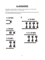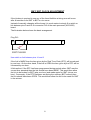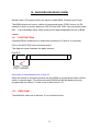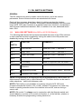
1
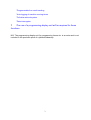
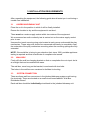
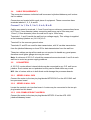
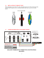
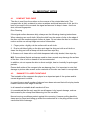
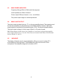
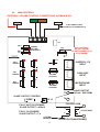
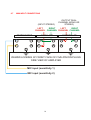
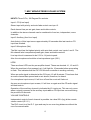
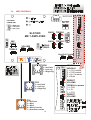
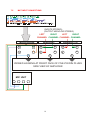
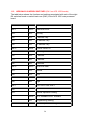
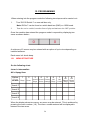
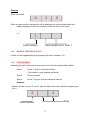
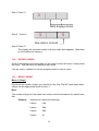
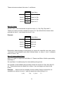
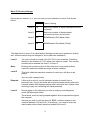
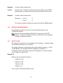
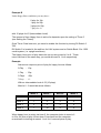
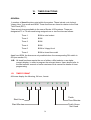
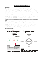
Version 3
SOUND LEISURE LTD.
39 INGS ROAD, LEEDS, LS9 9EW,YORKSHIRE,
ENGLAND
TEL:0113 2175000 FAX:0113 2175003
WWW.SOUND-LEISURE.COM
Email: [email protected]
COMPACT DISC INSTALLATION PROGRAMMING
SERVICE MANUAL
FOR SERIES 4 ACS1056 BOARD SYSTEMS
CONTENTS
1. Introduction
2. System Features
3. Installation Requirements
Page
1
2
4
3.1 Jukebox/Hideaway
4
3.2 Wall box
4
3.3 System Connection
4
3.4 Cable Requirements
5
3.5 Meters
5
3.5.1 Series 3 Wall box
5
3.5.2 Series 2 Wall box
5
3.5.3 1056 Combi Upright Jukebox
5
3.6 Installation of Compact Discs
6
3.7 Jukebox/Hideaway/Wall box Sample Wiring
6
4. Important Notes
7
4.1 Compact Disc Care
7
4.2 Damage to Laser Turntable
7
4.3 Locks
8
4.4 Making A Selection
8
5. Sequence of Operation
6. MK6 Mono Sound System
9
11
6.1 Warnings
11
6.2 MK6 Pre Amplifier
11
6.3 MK6 Power Amplifier
12
6.4 MK6 Slave Output
12
6.5 Karaoke
12
6.6 MK6 Controls
13
6.7 MK6 Input Connection
14
7. MK7 Stereo/Mono Sound System
15
7.1
MK7 Pre Amplifier PCB Setup
16
7.2
MK7 Slave Output
17
7.3
MK7 Power Amplifier
17
7.4
MK7 Controls
18
7.5
MK7 Input Connections
19
8. Speaker Wiring
9. GMT/BST Clock Adjustment
10. Background Music (BGM)
20
21
22
10.1 Constant BGM
22
10.1 Timed BGM
22
11. Dil Switch Settings
23
11.1 Wall box Switches
23
11.2 Hideaway/Jukebox Switches
24
12. Programming
26
12.1
Menu Structure
26
12.2
Moving Through Levels
27
12.3
Editing Menu
27
12.4
Exiting A Menu
28
12.5
Menu Format
28
12.6
Exiting A Program Mode
32
12.7
Happy Hour
32
12.8
Coin Lockout
34
12.9
Free Credit
35
13. Popularity Retrieval
14. Miscellaneous Function
15. Timed Functions
37
38
39
15.1 Timer Format
39
15.2 Coin Lockout
41
15.3 Timed Free Credit
42
16. Play Mechanism Set-up
43
17. C.D. Wall box Test
44
18. CD Mechanism Parts/Spares
45
1. INTRODUCTION
This manual covers the Series 4 range of Sound Leisure C.D. jukeboxes and
hideaway units.
The whole of the Series 4 range, which comprises a large number of different
machines and systems, is built from a small set of building blocks the main
components of which are listed below:
1. The player mechanism.
2. A MK6 or MK7 audio amplifier.
3. The ACS 1056 main processor board.
4. The ACS 1043 wall box processor board.
In addition to the above list, various other system components exist. These include:
coin mechanisms, selection keypads and displays, wall box distribution boards, etc..
From the components in the above lists, three distinct sub-systems can be
constructed which form the basis of all Series 4 equipment. These are:
1.
A hideaway unit which consists of: the player mechanism, an ACS
1056 processor board and an audio amplifier but no method of
obtaining selections.
These are designed for use in conjunction with a wall box and, as the name implies,
can be hidden, say, in a bar or a cellar.
2.
A wall box unit which displays and allows selections to be made in
exchange for coin input.
Up to three wall boxes can be connected to a jukebox or hideaway unit.
3.
A jukebox which effectively combines the functionality of hideaway and
wall box units.
Although the information in this manual was correct at the time of printing, the
manufacturer reserves the right to change it, without prior notice.
The contents of this manual may not be copied in part or full without prior consent
from Sound Leisure Ltd.
1
2. SYSTEM FEATURES
70 disc carousel
Up to 2100 track selections
Adjustable track running time
Adjustable consecutive track plays
Selections played in numerical order
Adjustable background music (B.G.M) disc band
Adjustable foreground music (F.G.M.) disc band
7 Day 24 hour real time clock (R.T.C.)
6 individual timers
Individual start & stop times for each timer
Each-day/every-day enable for each timer
Automatic music fader
Adjustable B.G.M. to F.G.M. volume
Manual enable for B.G.M. operation
Random play
Programmable price of play
Mechanical cash meter facility under software control
Microphone input with voice over activation and separate volume, bass and
treble controls
Auxiliary input socket for taped B.G.M. etc.
600 ohm slave output with gain preset
Provision for additional dual channel amplifier giving four channels in total
Retention of credit and selections on power fail situation.
*Programmable coin lock out
*Programmable B.G.M.
*Programmable 'Happy Hour' price of play
2
*Programmable free credit vending
*Auto logging of machine running times
*Full data retrieval system
*Data interrogator
*
The use of a programming display unit will be required for these
functions.
N.B. The programming display unit for programming timers etc. is an extra and is not
included in the purchase price of a jukebox/hideaway.
3
3. INSTALLATION REQUIREMENTS
After unpacking the equipment, the following guide should assist you in achieving a
trouble free installation.
3.1
JUKEBOX/HIDEAWAY UNIT
Place the unit in the position in which it will be finally installed.
Ensure the location is dry and the equipment is set level.
There must be a mains supply socket within two meters of the equipment.
We recommend an earth continuity test is carried out on the mains supply socket
prior to use.
Unscrew the transit securing wing nuts located at each corner underneath the play
mechanism. These wing nuts should be unscrewed sufficiently to completely clear
the underside of the play mechanism mounting when the mounting springs are fully
extended.
NOTE: We would like to bring to your attention that, since 1992, portable appliance
testing is required and that a certificate of compliance be issued.
3.2
WALLBOX
Firmly affix the wall box hanging bracket so that on completion the coin input slot is
at a height that can be reached with ease.
The wall box, once hung on the bracket, is anchored with two bolts.
The holes in the wall box are oversized to facilitate its leveling.
3.3
SYSTEM CONNECTION
There are three wall box connectors in the jukebox/hideaway system each having
five terminals. These are located on a small circuit board labeled: 'Wall Box
Distribution Board.'
Each wall box should be individually wired back to the jukebox-hideaway unit.
4
3.4
CABLE REQUIREMENTS
The connection between individual wall boxes and a jukebox/hideaway unit is done
via five cables.
Connectors are located within each piece of equipment. These connectors have
terminals labeled 1, 2, 3, A and B.
Connect 1 to 1, 2 to 2, 3 to 3, A to A, B to B.
Cables connected to terminals 1, 2 and 3 must have a minimum cross sectional area
of 0.75mm² (1mm diameter) when connecting wall boxes up to 50m away and
1.5mm² (1.5mm diameter) when the wall box is up to 100m away.
Terminals 1, 2 and 3 handle the wall box low voltage supply. This voltage is supplied
at the hideaway/jukebox as (14-0-14)V A.C.
Terminal 2 is the common ground return.
Terminals 'A' and 'B' are used for data transmission, with 'A' as data transmission
from the jukebox/hideaway unit and 'B' for data transmission from the wall box.
These two cables are signal lines and are not required to handle any great power,
therefore much lighter gauge wire may be used.
Note: A minimum of 25V A.C. should be measured across terminals 1 and 3 at each
wall box to avoid any power supply problems.
3.5
COIN METERS
A 12V D.C. meter without internal diode may be connected to any C.D. wall box or
jukebox. Such meters are not polarised so they can be fitted either way round.
N.B. Use of meters with an in built diode could damage the processor boards.
3.5.1
SERIES 3 WALL BOX
Connect the meter to the two pin plug labeled MTR/CON 5 on the ACS 1043 wall
box processor board.
3.5.2
SERIES 2 WALL BOX
Locate the sentinal coin interface board. A meter may be connected to the two pin
plug located on this board.
3.5.3 1056 COMBI UPRIGHT JUKEBOX
Connect the meter to the two pin plug labeled MTR/PL10 on the ACS 1056
jukebox/hideaway board.
5
3.6
INSTALLATION OF COMPACT DISCS
When standing in front of the C.D. play mechanism place the C.D's into the top of the
carousel with the picture face to the right and the clear face to the left, as shown
below.
CD IN CAROUSEL
DATA
SIDE
3.7
PICTURE
SIDE
JUKEBOX/HIDEAWAY/WALL BOX SAMPLE WIRING
2A
2A
R1
VR1
WALLBOX DISTRIBUTION BOARD C2
A
B
MPU
Wb1
A
B
Wb2
3
2
1
A
B
Wb3
3
2
1
3
2
1
+5V
0V
D1
3.15A
3.15A
Page motor wiring for
units without a
SLE 101A Board fitted
PAGE
MOTOR
D2
PAGE Sw1
14V
0V
14V
Power line cables on
Terminals 1+3
Signal cables on
Terminals A and B
WALLBOX TERMINATION CONNECTOR LOCATED WITHIN
WALLBOX.
6
PAGE Sw2
4.0 IMPORTANT NOTES
4.1
COMPACT DISC CARE
The disc is read from the surface on the reverse of the printed label side. The
compact disc is fairly resistant to minor scratches and small amounts of dirt, but it is
best to be careful not to scratch the signal surface and to keep it clean - free from
dust, dirt and fingerprints.
Disc Cleaning
If the signal surface becomes dirty, always use the following cleaning instructions:When cleaning use a soft cloth. Wipe the cloth from the center of disc to the edge of
the disc until the complete signal surface is clean. Do not clean the disc in a circular
motion as this can corrupt large amounts of information.
1. Finger prints:- slightly rub the surface with a soft cloth.
2. Dust or dirt blow lightly on the disc and wipe the dirty part with a soft cloth or
clean the dirty part with a damp soft cloth and then wipe dry.
3. Grease or oil clean with a soft cloth dampened with ethyl alcohol, then wipe dry.
N.B. Conventional liquids and sprays used to clean records may damage the surface
of the disc. Use of such a cleaner is not recommended.
In addition, do not expose the disc to direct sunlight, heat or humidity for prolonged
periods.
Ensure both sides of the compact disc are damage free. It is important to note that
damage to picture side as well as the read side of the disc can result in corrupt data.
4.2
DAMAGE TO LASER TURNTABLE
The turntable of the compact disc player is an important part of the system and its
correct alignment is critical.
In recent times a small number of players have been returned that will not play tracks
located near the outer edge of the disc.
In all cases the turntable shaft was bent off true.
It is considered that the only way this could happen is by impact damage, such as
that caused by the clamp head slamming into the turntable.
Normal running conditions protect against this occurring. However pulling back the
clamp arm by hand and letting go whilst the mechanism is in the play position could
cause this kind of damage.
7
4.3
LOCKS
Some machines are fitted with two locks and require two keys to be used
simultaneously.
4.4
MAKING A SELECTION
Five numbers need to be entered via the keypad to make one selection.
The CD mechanism can hold a maximum of 70 discs.
Each disc location is identified by a three digit number i.e. 100 to 169.
Example: To select a disc in location 145 enter the three digit number which
identifies that disc, i.e. 145.
Having entered the disc number you now need to enter a two digit number for the
track you wish to play from that disc. The track number must be in the range: 01 to
30.
8
5. SEQUENCE OF OPERATION
The appropriate amount in coins is inserted into the jukebox to establish a credit.
Once the jukebox has accepted sufficient coins, the credit lamp will illuminate
indicating hat the jukebox is ready to accept a selection.
A selection is entered in two stages. Firstly, a disc is selected by entering a three
digit number relating to its position in the carousel. Secondly, the two digit number
corresponding to the selected track is entered.
When the disc and track information has been entered, the display will blank
momentarily. If no more credits are established the display will show the last played
disc and track.
If, instead, multiple credits exist, the display will remain blank awaiting a further
selection input. If no selection is entered, the display will revert back to showing the
last played disc and track while still retaining all credits.
A selection has now been made. The ACS 1056 main processor board responds by
energising the scan relay which, in turn, applies power to the scan motor via contacts
on the trip relay.
The scan motor is a D.C. motor which can be driven in either direction. When driven
in one direction, the carousel is allowed to rotate (scan mode). As the carousel
rotates, its position is monitored via the carousel opto unit at the front of the play
mechanism.
The output of this opto unit is fed into the ACS 1056. The opto unit outputs two
signals:1.
the sync signal which occurs once every full turn of the
carousel,
2.
the count signal which occurs for every disc location.
These signals are generated by holes drilled in a timing disc at the front of the
carousel.
There are 70 holes evenly spaced around the circumference of the disc, one for
each disc location and count. One further hole is drilled in order to produce the sync
signal.
N.B. The timing disc position, relative to the carousel, is set at the factory and
should never be adjusted.
Once the sync position is found the ACS 1056 monitors the count signal. When the
count signal matches the selection, the carousel is halted. This is achieved by
9
energising the trip relay which reverses the power supply polarity to both the scan
motor and the latch solenoid. This causes the scan motor to reverse its direction of
rotation and the latch solenoid to de-energise. When the latch solenoid drops out the
latch engages the ratchet teeth and prevents the carousel from rotating in the
reverse direction (as it would, otherwise, tend to do).
The transfer cycle now commences causing the disc to be presented and clamped to
the CD player. When this is done, micro switch MS2, is actuated informing the main
processor board that the disc is in position. Shortly afterwards, the scan relay is deenergised via micro switch, MS1, thus removing power from the scan motor.
Once the disc is loaded the ACS 1056 board issues a reset signal to the CDM 12
laser player, thus clearing the last table of contents (T.O.C.). A further command is
issued to the CDM 12 player asking it to send the new T.O.C. back to the ACS 1056
board. Once the T.O.C. is read the processor 'knows' how many tracks are on the
disc. It then sends a command to tell the player to pause at the end of the track.
At this point a calculation is made by the processor to ensure that the track number
selected, 'n' , is within the range of tracks available on that particular disc.
The processor now informs the player of the required track number, 'n' , followed by
a command to clear the pause flag. Programming is now complete and track , 'n' , is
played.
Whilst playing the track, the ACS 1056 board monitors data from the CDM 12 player
such as track time and whether or not the next track has been reached.
When the 'next track reached' signal is issued the player is placed in pause mode. If
any more tracks are to be played the sequence restarts at the point indicated by the
#, above, otherwise the ACS 1056 will tell the CDM 12 to stop.
If the laser system fails to initialise the disc, the ACS 1056 will try once more before it
is logged as a faulty disc in memory.
When a track has been played successfully (the 'next track reached' signal has been
received) the processor initiates a reject cycle. This is done by energising the scan
relay thus re-applying power to the scan motor. The disc is now taken from the play
position and returned to the carousel.
As the lift arm returns to its rest position, micro switch MS3 de-energises the trip
relay. If no more selections exist, the scan relay also de-energises and the ACS
1056 awaits further selections.
If, instead, further selections do exist, the scan relay remains energised and the
carousel rotates to find the next selection.
10
6. MK6 MONO SOUND SYSTEM
6.1
WARNINGS
6.1.1 Damage to the sound fader circuit on the ACS1056 Board may occur if
the amplifier is unplugged whilst the machine is switched on.
6.1.2 Sound Leisure MK6 amplifier is not suitable for connection to a 100V
line system.
6.2
MK6 PRE-AMPLIFIER
INPUTS:- Three 5-pin, 180 Degree Din sockets.
Input 1 CD(Line Input)
This input has priority and auto-fade control over input 2.
The two stereo inputs are first combined into one mono signal before being
split into two channels each with pre-set gain, bass and treble controls.
Input 2 Auxiliary (Aux Line Input)
Auto-fade-in of this input occurs approximately 45 seconds after last track on
CD input has finished.
Input 3 Microphone (Mic)
The Mic input has the highest priority with auto-fade control over inputs 1 and
2. The Mic channel also incorporates preset gain, bass and treble controls.
Line Input level assumed to be: 0.5V to 1V peak-to-peak.
Also: the microphone should be a low impedance type (600 ).
VOLUME CONTROLS
Independent control of each channel is possible via a dual 22k (log) slider remote
volume control (R.V.C.).
The RVC circuit is of the D.C. type and may be run over long distances without the
use of screened cable.
11
6.3
MK6 POWER AMPLIFIER
Frequency Range15Hz to 20kHz with flat response.
Load impedance 4 Ohms minimum.
Power output 60W per channel, r.m.s., into 4Ohms .
The power output stage is overload protected.
6.4
MK6 SLAVE OUTPUT
The slave output is taken from pin, T3, on the pre-amplifier board. The signal ground
for the slave amplifier can be picked up on the MK6 amplifier chassis. The slave
output signal is controlled by the potentiometer, VR12, on the pre-amplifier board.
The slave output voltage is in the range: 600mV to 3V peak-to-peak.
N.B. When fitting a Sound Leisure slave amplifier it is necessary to upgrade the amplifier
power supply fuses from 3.15A to 4A. These fuses are located on the main ACS1056 board
and are denoted: F1 and F2.
6.5
KARAOKE
The facility of karaoke can be accomplished by lifting one end of resistor R71
on the MK6 pre amp top board. This disables the voice over function of the
microphone. See amplifier diagram for location of R71.
12
6.6
MK6 CONTROLS
EXTERNAL VOLUME CONTROL CONNECTIONS VIA MAIN M.P.U.
Green
Brown
Yellow
White
4 WAY RIBBON CABLE
CONNECTS TO JUKEBOX M.P.U.
Q1
CH II
CH I
PRESET
VOLUME
CONTROLS
AGC CONTROL.
DO NOT ADJUST
(LEAVE TURNED FULLY
CLOCKWISE)
VR1
R 71
CH II
TREBLE
B
A
S
S
CH I
TREBLE
B
A
S
S
MIC
TREBLE
B
A
S
S
C11
JUKEBOX / CD
INPUT
AUX
VOLUME
CONTROL
AUXILIARY
INPUT
MICROPHONE
INPUT
MIC
VOLUME
CONTROL
T3
SLAVE OUTPUT
600 mV / 600 OHMs
SLAVE OUTPUT CONTROL
VR 12
ACW
T4
(600/600) OHM
FULLY ANTI CLOCKWISE
SLAVE OUTPUT = 600mV
S
S
TO AUX AMP
FULLY CLOCKWISE
SLAVE OUTPUT = 3 V
F
SYSTEM
GROUND
13
F
ISOLATION TRANSFORMER
6.7
MK6 INPUT CONNECTIONS
(INPUT STEREO)
(OUTPUT DUAL
CHANNEL MONO OR
STEREO)
RIGHT
LEFT
LEFT
RIGHT
CHANNEL CHANNEL CHANNEL CHANNEL
MICRO-PHONE
AUXILLARY
JUKEBOX / CD
3
1
3
1
3
1
5
4
5
4
5
4
2
2
2
VIEWED LOOKING AT FRONT FACE OF FIVE-PIN DIN PLUGS.
SIDE VIEW OF AMPLIFIER
MIC input (sensitivity 1)
MIC input (sensitivity 2)
14
7. MK7 MONO/STEREO SOUND SYSTEM
INPUTS Three 5-Pin, 180 Degree Din sockets.
Input 1 CD (Line Input)
Stereo input with priority and auto-fade control over input 2.
Each channel has pre-set gain, base and treble controls.
In addition the stereo channels can be combined to form two, independent, mono
channels.
Input 2 Auxiliary (Aux Line Input)
Auto-fade-in of this input occurs approximately 60 seconds after last track on CD
input has finished.
Input 3 Microphone (Mic)
The Mic input has the highest priority with auto fade control over inputs 1 and 2. The
Mic channel also incorporates preset gain, bass and treble controls.
Line input level is assumed to be 0.5V to 1V peak-to-peak.
Also: the microphone should be a low impedance type (600 ).
LEDS
There are three LED's on the pre-amplifier board. These are denoted: L1, L2 and L3.
When the machine is first powered up L1 will light for 10 seconds before proceeding
to flash. This indicates that the PIC 16C84 micro-controller is working correctly.
When an audio signal is detected at the CD input, L2 will illuminate. This shows that
an audio channel has opened and music should, therefore, be heard.
If a microphone input occurs, L2 will turn off and the music will fade out.
As soon as microphone input ceases, L2 will turn on again and the CD audio signal
will fade back in.
Operation of the auxiliary channel is indicated by L3 turning on. This can only occur
when a signal is present at the auxiliary input and no CD input has occurred during
the previous 60 seconds.
VOLUME CONTROLS
Independent control of each channel is possible via a dual 22 k (log) slider remote
volume control (R.V.C.).
The RVC circuit is of the D.C. type and may be run over long distances without the
use of screened cable.
15
7.1
MK7 PRE-AMPLIFIER SET-UP
Set stereo/mono link, LK1, to: M for mono (normal pub installation).
ST for stereo, if required.
Leave LK2 in the position shown on the pre-amplifier component layout diagram.
Set 8-way dil switches, SW1, to
1
ON
5
OFF
2
ON
6
OFF
3
ON
7
OFF
4
ON
8
OFF
The function of the various potentiometers and their initial settings are shown in the
following table:
CONTROL
CHANNEL 1
CHANNEL 2
INITIAL SETTING
Master Volume
VR1
VR2
Centre
Slave Volume
VR3
VR4
Centre
Mid-Range
VR5
VR6
Centre
Treble
VR7
VR8
For 'Best' Sound
Bass
VR9
VR10
For 'Best' Sound
AUXILLIARY
MICROPHONE
VR11
VR12
Centre
Treble
VR13
For 'Best' Sound
Bass
VR14
For 'Best' Sound
Volume
16
7.2
MK7 SLAVE OUTPUT
The slave outputs are available at connector CON5 as follows:
Pin 1 = Mute Output
Pin 2 = Mic Signal Output
Pin 3 = Channel 1 Music Signal Output
Pin 4 = 0V Earth
Pin 5 = Channel 2 Music Signal Output
Connections to these outputs should be done with a four-core screened cable and
terminated at CON1 on MK7 slave amplifier input. CON1 is a 5-pin 180 Degree DIN
socket with the following pin-out:
Pin 1 = Channel 2 Music Signal Input
Pin 2 = 0V Earth
Pin 3 = Channel 1 Music Signal Input
Pin 4 = Mute Input
Pin 5 = Mic Signal Input
7.3
MK7 POWER AMPLIFIER
Frequency Range: 15Hz to 20kHz flat response.
Load impedance: 4 minimum.
Power output: 150W per channel, r.m.s., into 4Ohms .
17
7.4
MK7 CONTROLS
PSU FROM
POWER AMP
Con 6
SLD1000
3 2 1
MID FREQ.
CH2 CH1
TB1
1 = NEG (-Vs.)
2 = 0 V. Earth
3 = Poz (+Vs.)
CH2
SLD1000
MK 7 AMPLIFIER
MIC
BASS
BASS
TREBLE
CH2
BASS
ON
3
2
1
CH2
TREBLE
SW1
VR14
MONO
STEREO
VOLUME
LK2
TREBLE
VR13
VR12
VR11
MIC
AUX
CH1
CH1
CH1
LK1
SLAVE OUT GAIINS
VR 3
VR 4
CH1
CH2
PIN
3
1
5
4
2
TB1
2 = 0v Earth
3 = Left sig.
1 = Right sig.
CH2
PIN
3
1
5
4
2
2 = 0v Earth
3 = Left sig.
5 = Right sig.
3
2
1
CH1
PIN
3
1
5
4
2
2 = 0v Earth
3 = Mic 1
5 = Mic 2
4 = Music Overide
1 = Autofade overide
18
5
4
3
2
1
5
4
3
2
1
TO RVC
MODULE
1 = CH1 control
2 = CH2 control
3 = 0v. Common
4 = Mute
PRESET
VOLUME
SIGNAL to power
3 = CH2
2 = 0v.
1 = CH1
PRESET
VOLUME
7.5
MK7 INPUT CONNECTIONS
(INPUTS STEREO)
(OUTPUT MONO OR STEREO)
RIGHT
LEFT
LEFT
RIGHT
CHANNEL CHANNEL CHANNEL CHANNEL
MICRO-PHONE
AUXILLARY
JUKEBOX / CD
3
1
3
1
3
1
5
4
5
4
5
4
2
2
2
VIEWED LOOKING AT FRONT FACE OF FIVE-PIN DIN PLUGS
SIDE VIEW OF AMPLIFIER
MIC UNIT
19
8.0
SPEAKER WIRING
The optimum load impedance for Sound Leisure amplifiers is 4 and should be
regarded as a minimum value - do not go below.
The following diagrams depict various parallel/serial combinations of 8 speakers and
the resulting equivalent load impedance.
9.
8 OHMS
4 OHMS
4 OHMS
5.33 OHMS
8 OHMS
20
GMT/ BST CLOCK ADJUSTMENT
If the jukebox is required to use any of the timed facilities a timing error will occur
after a transition from GMT to BST or vice versa.
Instead of manually changing all the timers it is much easier to simply fit a switch or
link between pins 9 and 14 on connector PL3 of the main processor (ACS1056)
board.
The illustration below shows the basic arrangement.
Plug PL3
14
9
1
SWITCH/LINK
Use switch or link between pins 14 and 9
If the link is MADE then the time given by the Real Time Clock (RTC) will be reduced
by one hour. On the other hand, if the link is OPEN the time given by the RTC will be
increased by one hour.
It follows that: If the RTC had been programmed during periods when GMT was the
current time standard then the link should have been MADE. This would then allow
the link to be broken for BST (plus one hour) and made again for GMT (minus one
hour). Conversely, if the RTC had been set during the summer (BST current) then
the link should have been OPEN. This would then allow the link to be made for GMT
in the autumn.
21
10. BACKGROUND MUSIC (BGM)
Sound Leisure CD systems offer two ways to obtain BGM: Constant and Timed.
The BGM volume can be set, relative to foreground music (FGM) volume, by DIL
switches 5 and 6 on switch bank one (SW1) of the ACS 1056, main processor board.
N.B.
A kit is available which offers more precise and independent control of BGM
volume.
10.1
CONSTANT BGM
Constant BGM is achieved by a switch/link across pins 10 and 14 of connector
PL3 on the ACS 1056 main processor board.
The diagram below illustrates the basic scheme.
Plug PL3
14
10
1
SWITCH/LINK
Use switch or link between pins 14 and 10
When the switch is closed the jukebox will play BGM on a permanent basis until the
switch is opened again. The discs selected for BGM will be that band previously
programmed into: Menu 5, levels 3 and 4 (See Section 13).
10.2
TIMED BGM
Timed BGM is dealt with in Section 16, as a timed function.
22
11. DIL SWITCH SETTINGS
GENERAL
The DIL switches are used to enable various functions, and to set various
parameters. Some of these functions are associated with timers.
Each wall box processor board has a bank of switches as does the jukeboxhideaway processor board. However, the present jukebox/hideaway main processor
board (ACS 1056) also functions as a wall box board and, therefore, incorporates a
wall box board switch-bank denoted, SW2, in addition to its own, dedicated switch
bank, SW1.
11.1
WALL BOX SETTINGS (Also SW2 on ACS 1056 Boards)
The following table shows the functions associated with each of the 8 DIL switches.
In each case the function is enabled by turning the switch to the ON position and
disabled by turning it to the OFF position.
DIL
FUNCTION
COMMENTS
SW 1
Coin Lock-out
Used with Timer 1 - see Note 1
SW 2
Happy Hour
Used with Timer 5 - see Note 1
SW 3
Timed Free Credit
Used with Timer 6 - see Note 1
SWITCH
SW 4
Not used
SW 5
P-O-Pularity
Used in conjunction with DIL switch 7
SW 6
Retain Credits and
Selections
Depends on software - see Note 2
SW 7
Programming Enable
Used with Operator Switch - see Note 3
SW 8
Permanent Free Credit
NOTE 1:Programming of the timers can only be accomplished by use of either: an
Alpha-numeric display unit or a Mini-Selector unit. This latter device can be used to
make selections. - useful with hideaway units.
NOTE 2:This facility is only available on systems using the ACS 1056 main
processor boards with Version 12.8, or later, software. Its purpose is to retain any
credits or pending selections when the machine is turned off, such as during a
service call.
NOTE 3:DIL switch 7 is always used in conjunction with the Operator switch and
should only be on at one unit in a multi-unit system, ie. at the wall box, jukebox or
hideaway at which the programming is being carried out.
23
11.2
HIDEAWAY/JUKEBOX SWITCHES (SW1 on ACS 1056 boards)
The table below shows the functions and settings associated with each of the eight
DIL switches found on switch bank one (SW1) of the ACS 1056 main processor
board.
DIL SWITCHES
FUNCTION
SW 1
SW 2
RANDOM PLAY
OFF
OFF
No Play
ON
OFF
5 Minutes Play
OFF
ON
10 Minutes Play
ON
ON
15 Minutes Play
SW 3
SW 4
TRACK LENGTH
OFF
OFF
Full Length
ON
OFF
4 Minutes
OFF
ON
5 Minutes
ON
ON
6 Minutes
SW 5
SW 6
BGM VOLUME
OFF
OFF
Normal
ON
OFF
Low
OFF
ON
Middle
ON
ON
High
SW 7
FACTORY USE ONLY
ON
OFF
Normal Operation Setting
SW 8
SITE NUMBER EDIT ENABLE
ON
Programming Setting
OFF
Normal Operation Setting
24
The 'Random Play' function plays a random track if no customer selection has been
made during the period given by the table. The 'Track Length' function limits the
length of time a track can play to the maximum time quoted in the table. The 'Site
Number Edit' function requires the use of either a Psion Organiser data retrieval
unit or a Mini-selector.
25
12. PROGRAMMING
When entering into the program mode the following two steps must be carried out:1.
Turn 'ON' Dil Switch 7 on one wall box only.
Note: Dil Sw 7 can be found on switch bank two (SW2) on 1056 board.
2.
Turn the service switch, located at front of play mechanism to the 'OFF' position.
Once the machine has entered the program mode it responds by displaying two
zeros as shown below:-
0
0
A minimum of 5-menus may be entered with an option of up to nine depending on
installed software.
Each menu is 4-levels deep.
12.1
MENU STRUCTURE
On the following chart:
Int-md = Intermediate
HH = Happy Hour
Option
1
2
LEVEL
Plays
Coins
3
4
5
6
Int-md Int-md Factory HH
Plays Coins Settings Plays
7
HH
Coins
8
9
HH
HH
Bonus Bonus
Plays Coins
Level 1
Level 2
Level 3
Level 4
When the display shows two zeros, any menu may be entered. This is achieved by
pressing the menu number (1-9). The menu number entered will be displayed in
between the two zeros.
26
Example
Menu 2 selected
0
2
0
When a menu number is pressed it will be displayed for a short while before the
display changes to show the contents of the first level in the menu.
i.e.
1
Level number
12.2
Data locations for level 1
MOVING THROUGH LEVELS
Levels can be stepped through by pressing the level numbers (1-4).
12.3
EDITING MENU
Assuming you are in the correct menu and level, follow the steps shown below:Step 1:
Press 'C' key to overwrite old data.
(The middle to right displays will blank)
Step 2:
Enter new data.
Step 3:
Press 'C' key to lock new data into memory.
Example
Assume we are in menu 2, level 3, and the data at this level requires changing from
4 to 5.
3
4
Data
Level number
27
Step 1: Press 'C'
3
Both displays blank
3
Step 2: Press 5
5
New data is entered
Step 3: Press 'C'
The display will now blank totally for a short while and reappear. (New data
is now loaded into memory).
12.4
EXITING A MENU
Once all the editing has finished and you are ready to leave the menu, simply press
the 0 key. This will return the display to two zeros.
You are now in a position to exit the program mode or enter a menu.
12.5
MENU FORMAT
Menu 1 (Plays)
Decide on the number of plays you require for 10p, 20p, 50p & £1 and insert these
values into the appropriate levels of menu 1.
Note:
The number of plays for the lowest coin value must be entered into the lowest level
first.
Example:
Suppose we require the following:0 plays
- 10p
0 plays
- 20p
2 plays
- 50p
5 plays
- £1
28
These values are entered into menu 1 as follows:-
Menu 1
Plays Menu
Level 1
0
Plays for 10p
Level 2
0
Plays for 20p
Level 3
2
Plays for 50p
Level 4
5
Plays for £1
Menu 2 (Coins)
Sound Leisure coin mechanism accept four coins, i.e. 10p, 20p, 50p and £1.
These coin values must be entered into menu 2 in 10p units with the lowest value
entered into level 1, next lowest into level 2, etc.
Example:
Menu 2
Coins Menu
Level 1
1
10p level
Level 2
2
20p level
Level 3
5
50p level
Level 4
10
£1 level
Remember, when deciding on what plays you require for a specific coin value, menu
1 and menu 2 are related to each other via their levels, i.e. menu 1, level 1, relates to
menu 2, level 1, etc.
Menu 3 (Intermediate Plays)
Menu 3 is used in conjunction with Menu 4. Please read Menu 4 before proceeding
with Menu 3.
We use Menu 3 to obtain plays for intermediate pricing levels.
An example of intermediate plays would be those we require for 30p, 40p, 60p, £2,
etc. Those which are not catered for in Menu 1 (are not single unit coins of the
realm).
Example:
Assume we have already set the number of plays required for our
standard coin values in menu 1, and we require two other pricing levels.
1 play
30p,
29
11 plays
£2
Enter the number of plays required into menu 3, levels 1 and 2 as follows:-
Menu 3
Intermediate Plays
Menu
Level 1
1
First Intermediate Play
Level 2
11
Second Intermediate
Play
Level 3
0
Third Intermediate Play
Level 4
0
Fourth Intermediate Play
Menu 3 and menu 4 are related to each other in the same way as menu 1 and
menu2.
Menu 4 (Intermediate Coins)
Menu 4 enables you to generate values for which there is no coin, e.g. 30p, 40p,
60p, etc.
Following on from our previous example:1 play
- 30p
11 plays
- £2
Enter the intermediate prices into menu 4, levels 1 and 2 as
shown below:Remember they must be in 10p units, i.e. £2 = 20 x 10p units, etc.
Menu 4
Intermediate Pricing Menu
Level 1
3
First Intermediate Price
Level 2
20
Second Intermediate Price
Level 3
0
Third Intermediate Price
Level 4
0
Fourth Intermediate Price
30
Menu 5 (Factory Settings)
Having set up menus 1 to 4, you can now turn your attention to menu 5 as shown
below.
Menu 5
Factory Setting
Level 1
70
Maximum number of discs selectable from the
keyboard.
Level 2
3
Maximum number of tracks played
consecutively from any one disc
Level 3
60
BGM/Random Disc Band (Start)
Level 4
69
BGM/Random Disc Band (Finish)
The data shown in menu 5 is called default settings and are set in production at final
test. All these values may be changed to suit a particular installation.
Level 1
You may not wish to install a full 70 C.D's in your machine. Therefore,
decide on the number of C.D.'s which you intend to install. This number
should then be entered into level 1 of menu 5.
Note:
Entering the correct number of discs into level 1 ensures that discs
cannot be selected outside the range of those installed.
Level 2
This level holds the maximum number of tracks you will allow to be
played
from any disc consecutively.
Example
If this level is set to 4, and a customer selects six tracks from a
particular disc, four of the tracks will be played consecutively before the
carousel rotates 360 degrees playing other selections as it rotates, then
returning to play the remaining two tracks selected.
Level 3
Decide where in the carousel you wish to locate your background
music (BGM)/random discs.
These discs 'must' be kept grouped together and not spread throughout
the carousel.
Assume you wish to use ten discs for BGM / random, located in the
carousel between 100 and 109 (10 locations), you need to enter the
start location where these discs are located into Level 3.
31
Example
Location 100 is entered as 0
Level 4
As with Level 3, where you entered the start location of your BGM /
random discs, you also need to enter the end location into Level 4.
Example
Location 109 is entered as 9.
Therefore,
Level 3
-0
Level 4
-9
The above example will allow ten discs to be used for BGM/random.
12.6
EXITING PROGRAM MODE
Turn the service switch on the front of the mechanism back to the
'OPERATE' position.
Note Wait one full minute before Dil Switch 7 is returned to the 'OFF'
position. Failure to wait one full minute could result in your program
changes not being accepted.
12.7
HAPPY HOUR
The Happy Hour function is not available on all machines. It depends upon
the software installed in your machine.
All upright jukeboxes manufactured with single jukebox boards, i.e. 1056
Combi Boards, are equipped with the Happy Hour software, i.e.
If installed, it allows the price of play to be changed to a more favourable
price of play for a given time.
Example A
Assume the normal price of play is:0 plays for 10p
0 plays for 20p
2 plays for 50p
5 plays for £1
with 1 play for 30p (Intermediate Level)
32
Example B
Under Happy Hour conditions you may have:0 play for 10p
1 play for 20p
3 plays for 50p
7 plays for £1
with 15 plays for £2 (Intermediate Level)
The amount of time Happy Hour is active for depends upon the setting of Timer 5
(see Setting the Timers).
Once Timer 5 has been set, you need to enable this function by turning Dil Switch 2
'ON'.
Dil Switch 2 is located in the wall box for HAU system and on Switch Bank 2 for 1056
combi system (i.e. upright machines).
The Happy Hour price of play has to be set up using menu's 6 to 9. These
menu's are set in the same way you would set menu's 1 to 4 respectively.
Example:
Assume we require a price of play for happy hour as follows.
0 Play
- 10p
1 Play
- 20p
3 Plays
-50p
7 Plays - £1
With an intermediate level of £2 (15 plays)
Menu's 6 - 9 would be set as follows.
Menu 6
Menu 7
Menu 8
Menu 9
Level 1
0
1
15
20
Level 2
1
2
0
0
Level 3
3
5
0
0
Level 4
7
10
0
0
When happy hour is active via timer 5, the computer looks to menu's 6
to 9 for it's price of play. When timer 5 has timed out the computer
reverts back to looking at menu's 1 to 4 for it's normal price of play.
33
12.8
COIN LOCKOUT
Coin lockout is as its name implies - coins are rejected by the machine when
this facility is activated. Coin lockout is available on all free standing upright
machines fitted with the 1056 Combi MPU.
However, when this feature is required on a wall box, the wall box must be
fitted with Eprom Version 9.04.
Choose one of the examples below for your particular system.
Example A (1056 Combi Upright Machines)
1.
Turn 'ON' Dil Switch 1 on Switch Bank SW2.
2.
Program Timer -1 with alphanumeric display.
3.
Remove link LK3 on 1056 board if fitted.
See section on Setting the Timer for programming Timer -1.
Example B (Series 2 Wall box)
1.
Remove the four inhibit wires attached to the sentinel wall box interface
board.
These wires originate from the sentinel coin mech 15 way connector strip:Pins: 8 - 11 - 12 and 13
After removing these four wires from this interface board, short all four wires
together and connect via one lead to the Terminal -1 on the wall box
processor 10 way terminal strip.
2.
Replace all wall box Eproms for 9.04.
3.
Turn on Dil Switch one in wall box.
4.
Program Timer -1 with fluorescent pack.
5.
Make sure Terminal 1 on w/b processor(s) are screwed down tightly.
6.
If Series 2, replace H/A prom with P39.
7.
If Series 3, replace H/A prom with V1.3J onwards.
34
Example C (Series 3 Wall box)
1.
Replace Eprom for 9.04
2.
Turn 'ON' Dil Switch 1 in wall box.
3.
Program timer one with alphanumeric display.
4.
Remove link LK1 on wall box board.
See section on Setting the Timers for programming Timer -1 .
12.9
FREE CREDIT
Free credit can be established in two ways:-
1.
1.
Constant.
2.
A programmed number of credits (timed).
Constant
Constant free credit can be established via Dil Sw 8, i.e.
Example A (1056 Combi)
Turn 'ON' Dil Sw 8 on switch bank SW2.
Example B (Series 2 & 3 Wall boxes)
Turn 'ON' Dil Sw 8.
2.
A Programmed Number of Credits (Timed)
A programmed number of credits is different to constant free credit because a
pre-determined number of free credits can be made available at a particular
time. This time is governed by the setting of Timer -6.
Example
Suppose we require 10 credits at 5.30 p.m. on certain days of the week.
Set your alphanumeric display unit to show Timer 6
NOTE: Timers are set using the 24 hour format.
35
Timer 6
T6
S
0
0
0
0
F
0
0
0
0
Finish
Time Minutes
Start Hours
Start Minutes
Finish Hours
Not Used
Set the start time to 5.30 pm
T6
S
1
7
3
0
F
0
0
0
0
Enter the number of free credits you wish to give into the Finish Time
Minutes section.
i.e. Assume you wish to give 10 free credits at 5.30 p.m., Timer T6
would be set as shown below.
T6
S
1
7
3
0
F
0
0
1
0
Minutes Section =10
Once Timer 6 has been set, you need to enable this function by turning
Dil Switch 3 'ON'.
Dil Switch 3 is located in the wall box for a HAU system and on Switch
Bank 2 (SW2) for 1056 Combi system (i.e. upright machines).
All you have to do now is set the days of the week you require the timed
free plays for.
Note
Once a programmed number of free credits are available, the Finished
Minute section of Timer 6 acts as a counter, decreasing its count as each
selection is made until the Finished Minutes section is zero at which time
no more free credits are available.
36
13 . POPULARITY RETRIEVAL
(VIA SELECTION BUTTONS)
UPRIGHT JUKEBOX (1056 Combi)
Turn 'ON' Dil Switches 5 & 7 on Switch Bank SW2.
WALLBOX
Turn 'ON' Dil Switches 5 & 7 on wall box MPU. (Wall box Eprom must be
V9.05)(HAU Eprom must be V1.3B or later).
NOTE
You need only turn 'ON' Switches 5 & 7 on either the wall box or the jukebox,
not both.
PROCEDURE
Turn service switch on front of play mechanism to the 'OFF' position.
Press 0 when the display shows '0 0'.
0
0
Do not press and hold the button. To activate any of the functions below
press and release the button. The display will start to flash, displaying the
least played C.D. followed by the number of times it has been played.
Press key no:1.
The display advances towards the most popular C.D., one location at a
time.
2.
The display steps back towards the least popular C.D., one location at a
time.
3.
As Key No. 1, only ten locations at a time.
4.
As Key No. 2, only ten locations at a time.
5.
Instant display of the most popular C.D.
6.
Instant display of the least popular C.D.
8.
Reset popularity.
37
14. MISCELLANEOUS FUNCTIONS
1.
Data Retrieval,
2.
Changing Site Number,
3.
Setting the Real Time Clock.
All these facilities require the use of either: an alpha-numeric display, a Mini-selector
or a Psion Organiser. Data regarding the use of these devices is given in various
documents as outlined below and should be referred to before use.
1.
The use of the alpha-numeric display is described in older versions of
this manual. N.B. It should be noted that the alpha-numeric display is
no longer available and has been replaced by the Mini-selector.
2.
The Mini-selector is a replacement for the alpha-numeric display and
comes complete with an operating manual covering all aspects of use
including that of setting the timers. The Mini-selector can also act as a
hand-held wall box - a useful facility when working on a hideaway unit
in a cellar.
3.
The Psion Organiser is used as an operators tool and comes complete
with the relevant documentation.
38
15.
TIMED FUNCTIONS
GENERAL
A number of timed functions exist within the system. These include: coin lockout,
'Happy-Hour', free credit and BGM. These functions are timed in relation to the Real
Time Clock (RTC).
There are six timers available to the user of Series 4 CD systems. These are
designated T1 to T6 with each being assigned one or two functions as follows:
Timer 1
BGM or coin lockout
Timer 2
BGM
Timer 3
BGM
Timer 4
BGM
Timer 5
BGM or 'Happy Hour'
Timer 6
BGM or timed free credit
Apart from BGM, the timers are only enabled when the corresponding DIL switch is
ON (see section 12).
N.B. All timed functions require the use of either: a Mini-selector or an alphanumeric display, in order to program the relevant timers. Users should refer to
the Mini-selector manual or earlier versions of this manual for details of timer
programming.
15.1
TIMER FORMAT
All timers display the following, 24 hour, format:
T6
S
0
0
0
0
F
0
0
0
0
Finish
Time Minutes
Start Hours
Start Minutes
Finish Hours
Not Used
39
TIMER FORMAT (cont)
N.B. In timed free credit, timer T6 has a slightly different format in that the finishtime hours is unused and the total number of free-credits offered is entered in the
corresponding minutes field. This then acts as a down-counter as each credit is used
until it reaches zero, at which point the free credit facility is disabled.
Additionally, each timer can be enabled or disabled for each or every day.
The display format in this mode is as shown below:
T n
D A Y S
E S M T W T F S
40
15.2
COIN LOCKOUT
Coin lockout is the facility whereby a machine will refuse any attempt to obtain credit
via insertion of coins. It does this by rejecting any coins input to the coin mechanism.
Coin lockout is available on all machines fitted with the ACS 1056 main processor
board. However, if this feature is required on a wall box, the wall box processor
board must be fitted with Eprom Version V9.04 or V9.06.
A number of examples are shown below for various system combinations, choose
one of the examples to suit your particular system.
EXAMPLE 1 Jukeboxes fitted with ACS 1056 boards
1. Turn 'ON' DIL switch 1 on switch bank 2.
2. Program timer T1 for start and finish times with a Mini-selector.
3. Remove link LK3, on ACS 1056 main processor board, if fitted.
EXAMPLE 2 Series 2 Wall box
1. Remove the four inhibit wires from the sentinel wall box interface board.
N.B. These wires originate at pins: 8, 11, 12 and 13 of the 15-way connector strip on
the sentinel coin mechanism.
2. These four wires should first be connected together and then to pin 1 on the wall
box processor 10-way terminal strip.
3. Replace all wall box Eproms for V9.04 or V9.06.
4. Turn DIL switch 1, ON, on main processor board.
5. Program timer T1 for start and finish times with a Mini-selector.
6. Make sure Terminal 1 on wall box processor(s) are screwed down tightly.
7. If it’s a Series 2 hideaway unit, replace Eprom with P39.
8. If it’s a Series 3 hideaway unit, replace Eprom with V1.3J onwards.
EXAMPLE 3: Series 3 Wall box
1. Replace Eprom for V9.04 or V9.06
2. Turn DIL switch 1, ON, on wall box main processor board.
3. Program Timer 1 for start and finish times with a Mini-selector.
4. Remove link LK1 on wall box board.
41
15.3
TIMED FREE CREDIT
Free credit can be established in three ways:1. Singly, via credit button on a wall box main processor board.
2. Constantly, by turning DIL switch 8, ON, either on a wall box main processor
board or switch bank 2 on an ACS 1056 board.
3. Timed.
The first gives a single credit for each press of the credit button. The second, gives
free credits whenever DIL switch 8 is ON. Timed free credit differs in that it allows a
predetermined number of free credits to be made available at a particular time by
setting timer T6.
EXAMPLE
Suppose 15 free credits are required at 5.30 p.m. on Monday and Tuesday, then
timer T6 should be programmed as follows:
Initial State:
T6
S
0
0
0
0
F
0
0
0
0
0
0
0
Set start-time to 1730 hours
T6
S
1
7
3
0
F
0
Enter number of free credits into finish-time minutes section
T6
S
1
7
3
0
F
0
0
1
5
The day of the week is then programmed thus:
T n
D A Y S
* *
M T
* * * *
Once the timer is set the function must be enabled by turning DIL switch 3 to the ON
position. DIL switch 3 is located on the wall box main processor.
42
16. PLAYER MECHANISM SET-UP
GENERAL
The fundamental mechanism timing is derived from the front timing disc in
conjunction with a pair of slotted opto-switches (optos). These optos detect the
presence of holes in the timing disc. The disc has 70 'count' holes, one for each disc
position, plus a single 'sync' hole used to synchronise the whole timing and counting
process.
WARNING The position of the main timing disc is set at the factory and should
never be moved.
An LED, L2, on the ACS 1056 main processor board monitors the state of the count
opto such that: the LED is OFF when a hole is detected and ON otherwise.
The rear of the carousel has a 'face' ratchet, the teeth of which can be engaged by a
pawl.
This pawl is pulled into engagement by a spring and out of engagement by a
solenoid.
N.B. Over time there has been a change in nomenclature regarding these devices.
Initially, the pawl was called a 'latch arm', hence the term 'latch solenoid'. Later
versions of this manual have called the pawl a 'detent lever'.
OPTO UNIT SETUP
*
Position 1
POSITION
Detent Lever
(100)
Position 2
PULSE
LED
ON
PULSE
LED
OFF
PULSE
LED
ON
(153)
Sample of carousel
teeth at rear of
carousel
CAROUSEL
(135)
* Note
43
(117)
17. C.D. WALL BOX TEST
This test is designed for engineers on site and enables them to test the whether the
wall box, jukebox/hideaway unit or connecting cable is at fault.
1. Turn the machine off.
2. Disconnect the A and B lines on the wall box distribution board in the
jukebox/hideaway. Do not disconnect lines from terminals 1, 2 and 3.
3. Twist the A and B lines together to short them out.
4. Turn the machine on.
5. Note the selection being displayed on the wall box (last selection played).
6. Instigate a credit.
7. Make a new selection, i.e. any selection except that which was being displayed on
the wall box before credit was established.
8. If the wall box is working and the cable is undamaged, the data will be transmitted
down the wall box send line, B, and, because they are shorted together, back up
the wall box receive line, A. This will result in the wall box display being updated,
immediately, to the new selection entered.
If this is the result, then the wall box and cable are fine and the problem is at the
hideaway.
9. If the wall box display is not updated, then the test should be carried out on the
wall box alone as follows:
10. Turn the machine off.
11. Reconnect the A and B lines to the wall box distribution board.
12. Disconnect the A and B lines from the wall box taking care not to allow them to
short either together or to other items.
13. Link the A and B terminals on the wall box interface board and screw them down
firmly.
14. Repeat items 4 to 7.
15. If the wall box is working, the data will be transmitted from the wall box send
terminal, B, to the wall box receive terminal, A. This will result in the wall box
display being updated to the new selection entered.
16. If this is the result, then the wall box is fine and either the A or B lines are o/c.
17. If the wall box display is not updated, then the wall box MPU is likely to be faulty
and should be replaced.
N.B. Ensure the voltage between terminals 1 and 3 is at least 25V a.c.
44
18. C.D. MECHANISM PARTS/SPARES
Item No.
Description
350-14
Main Spindle
350-20
Magazine Drive Belt
350-21
M12 x 25 Hex. Hd. Screw
350-22
Tab Washer
350-23
Magazine Spacing Washer
353-00
Pinch Arm Assembly
360-00
Main Frame Assembly
361-00
Ratchet Paul Assembly
371-02
ACS 2047 PSU Assembly
381-00
Magazine Assembly
391-18
Switch Cam
392-11
Cam Follower
397-00
Camshaft Assembly
398-00
Clamp Arm Assembly
398-01
Clamp Head Assembly
398-25
Clamping Magnet
398-30
Disc Knock-off Lever
398-31
Disc Knock-off Lever Spacer
399-03
Clamp Arm Spring
400-05
Jockey Pulley Spring
400-10
Diabolo Arm Guide Shaft
400-26
Microswitch (Roller) (MS1 and MS2)
6410-64
Microswitch (White) (MS3)
400-93
Lift Arm Spring
45
Item No.
Description
403-00-03
CDM 12 Laser Player Assembly
404-00
Jockey Pulley Assembly
408-00
Diabolo/Lift Arm Opto Board Assembly
409-00
Transfer/Lift Arm Assembly
410-00
Motor/Gearbox Assembly
430-00
Reject/Scan Bracket Assembly
440-00
Main Opto Assembly
46