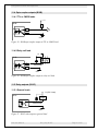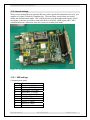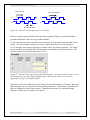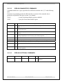
1
B10 series
Digital Device Interface
User Manual
Pyramid Technical Consultants, Inc.
1050 Waltham Street Suite 200, Lexington MA 02421 USA
US: TEL: (781) 402 1700 ♦ FAX: (781) 402-1750 ♦ EMAIL: [email protected]
Europe: TEL: +44 1273 493590
PSI System Controls and Diagnostics
1 Contents
Safety Information ......................................................................................................................................................6
Models...........................................................................................................................................................................8
Scope of Supply............................................................................................................................................................9
Optional Items ...........................................................................................................................................................10
Power supplies........................................................................................................................................................10
Signal cables and cable accessories.......................................................................................................................10
Data cables .............................................................................................................................................................10
Test connectors .......................................................................................................................................................10
Fiber-optic loop ......................................................................................................................................................10
Intended Use and Key Features ...............................................................................................................................11
Intended Use ...........................................................................................................................................................11
Key Features...........................................................................................................................................................11
Specification ...............................................................................................................................................................12
Installation .................................................................................................................................................................16
Mounting.................................................................................................................................................................16
Grounding and power supply .................................................................................................................................16
Connection to equipment ........................................................................................................................................17
Getting Started using the PSI Diagnostic Program................................................................................................18
Installing the PSI Diagnostic Program ..................................................................................................................18
Operating the B10...................................................................................................................................................18
Establishing communication with the B10..............................................................................................................19
Data tab ..................................................................................................................................................................20
B10 User Manual
B10_UM_081027
Page 2 of 56
PSI System Controls and Diagnostics
Setup tab .................................................................................................................................................................22
Device tab ...............................................................................................................................................................23
Circuit overview.........................................................................................................................................................25
B10A .......................................................................................................................................................................25
B10B .......................................................................................................................................................................26
B10C .......................................................................................................................................................................27
Electrical interfacing .................................................................................................................................................28
TTL inputs (B10A, B10C) .......................................................................................................................................28
TTL source.........................................................................................................................................................28
Relay source.......................................................................................................................................................28
Opto-coupler source...........................................................................................................................................28
TTL inputs (B10B) ..................................................................................................................................................29
TTL or CMOS source ........................................................................................................................................29
Switch or relay contacts source..........................................................................................................................29
TTL outputs (B10A) ................................................................................................................................................30
TTL loads...........................................................................................................................................................30
Opto-coupler photodiode load ...........................................................................................................................30
Opto-coupler outputs (B10B)..................................................................................................................................31
TTL or CMOS loads ..........................................................................................................................................31
Relay coil load ...................................................................................................................................................31
Relay outputs (B10B)..............................................................................................................................................31
General loads .....................................................................................................................................................31
Connectors .................................................................................................................................................................33
Front panel connectors...........................................................................................................................................33
Digital I/O ..........................................................................................................................................................33
Rear panel connectors ............................................................................................................................................34
Power input ........................................................................................................................................................34
Fiber-optic communications...............................................................................................................................35
Controls and Indicators ............................................................................................................................................36
Front panel controls ...............................................................................................................................................36
B10 User Manual
B10_UM_081027
Page 3 of 56
PSI System Controls and Diagnostics
Rear panel controls.................................................................................................................................................36
Address switch ...................................................................................................................................................36
Front panel indicators ............................................................................................................................................36
Rear panel indicators .............................................................................................................................................36
Power .................................................................................................................................................................36
Activity ..............................................................................................................................................................36
Network .............................................................................................................................................................36
Device ................................................................................................................................................................36
Internal settings ......................................................................................................................................................37
SW2 settings ......................................................................................................................................................37
JPR1 settings......................................................................................................................................................38
Software updates .......................................................................................................................................................39
Encoder reading feature ...........................................................................................................................................41
ASCII Communication .............................................................................................................................................43
ASCII Protocol – SCPI ...........................................................................................................................................43
Messages ............................................................................................................................................................43
Status registers ...................................................................................................................................................44
Host Commands.................................................................................................................................................44
ADDRESSING DEVICES............................................................................................................................44
IEEE 488.2 MANDATORY COMMANDS.................................................................................................45
IEEE 488.2 OPTIONAL COMMANDS.......................................................................................................45
B10 COMMANDS........................................................................................................................................46
ASCII Protocol – Terminal Mode...........................................................................................................................49
Fault-finding ..............................................................................................................................................................50
Maintenance...............................................................................................................................................................52
Returns procedure.....................................................................................................................................................53
Support .......................................................................................................................................................................54
Declaration of Conformity........................................................................................................................................55
Revision History.........................................................................................................................................................56
B10 User Manual
B10_UM_081027
Page 4 of 56
PSI System Controls and Diagnostics
B10 User Manual
B10_UM_081027
Page 5 of 56
PSI System Controls and Diagnostics
2 Safety Information
This unit is designed for compliance with harmonized electrical safety standard EN610101:2000. It must be used in accordance with its specifications and operating instructions.
Operators of the unit are expected to be qualified personnel who are aware of electrical safety
issues. The customer’s Responsible Body, as defined in the standard, must ensure that operators
are provided with the appropriate equipment and training.
The unit is designed to make measurements in Measurement Category I as defined in the
standard.
Although the B10 does not generate dangerous voltages, nor is it designed to measure directly
such voltages, in your application it may be controlling power supplies that do. Appropriate
precautions must be taken.
The unit must not be operated unless correctly assembled in its case. Only Service Personnel, as
defined in EN61010-1, should attempt to work on the disassembled unit, and then only under
specific instruction from Pyramid Technical Consultants, Inc. or their authorized distributors.
The unit is designed to operate from +24VDC power, with a maximum current requirement of
250mA. A suitably rated power supply module is available as an option.
The unit must be grounded by secure connection to a grounded conducting surface. If the unit is
mounted on an insulating surface, then one of the four mounting screws must be re-assigned as a
grounding connection.
Some of the following symbols may be displayed on the unit, and have the indicated meanings.
B10 User Manual
B10_UM_081027
Page 6 of 56
PSI System Controls and Diagnostics
Direct current
Earth (ground) terminal
Protective conductor terminal
Frame or chassis terminal
Equipotentiality
Supply ON
Supply OFF
CAUTION – RISK OF ELECTRIC SHOCK
CAUTION – RISK OF DANGER – REFER TO MANUAL
B10 User Manual
B10_UM_081027
Page 7 of 56
PSI System Controls and Diagnostics
3 Models
B10A
Digital device interface with eight TTL outputs, eight TTL inputs.
Encoder read facility. Includes PTC Loop Diagnostic host software.
B10B
Digital device interface with four optocoupled outputs, four
optocoupled inputs. Includes PTC Loop Diagnostic host software.
B10C
Digital device interface with four relay outputs, eight TTL inputs.
Includes PTC Loop Diagnostic host software.
B10 User Manual
B10_UM_081027
Page 8 of 56
PSI System Controls and Diagnostics
4 Scope of Supply
B10 model as specified in your order.
USB memory stick containing:
User manual
PSI Diagnostic software guide
Software installation guide
PSI diagnostic software files
USB drivers and utilities
Optional items as specified in your order.
B10 User Manual
B10_UM_081027
Page 9 of 56
PSI System Controls and Diagnostics
5 Optional Items
5.1 Power supplies
PSU24-45-1. +24 VDC 1.88 A PSU (100-250 VAC, 50-60 Hz, IEC C14 3-pin plug receptacle)
with output lead terminated in 2.1mm threaded jack.
PSU24-36-1. +24 VDC 1.5 A PSU (100-250 VAC, 50-60 Hz, IEC C8 2-pin plug receptacle)
with output lead terminated in 2.1mm threaded jack.
5.2 Signal cables and cable accessories
Cable, D subminiature 25-pin plug to bared ends, 3 m.
5.3 Data cables
Fiber-optic cable pair, 1 mm plastic, ST terminated, 5m.
Fiber-optic cable pair, 200 um silica, ST terminated, 5m.
5.4 Test connectors
Loopback test connector for the B10A.
5.5 Fiber-optic loop
A100 RS-232 to fiber-optic adaptor.
A200 USB to fiber-optic adaptor.
A300 fiber-optic loop controller / Ethernet adaptor.
A500 intelligent cell controller with Ethernet interface.
B10 User Manual
B10_UM_081027
Page 10 of 56
PSI System Controls and Diagnostics
6 Intended Use and Key Features
6.1 Intended Use
The B10A is intended for general control and monitoring applications using TTL level digital
inputs and outputs. Applications include reading switch and setting states, reading serial and
parallel data streams, reading position encoder pulses.
The B10 has design features which make it tolerant of electrically noisy environments, but the
place of use is otherwise assumed to be clean and sheltered, for example a laboratory or light
industrial environment. The unit may be used stand-alone, or networked with other devices and
integrated into a larger system. Users are assumed to be experienced in the general use of
precision electronic circuits for sensitive measurements, and to be aware of the dangers that can
arise in high-voltage circuits.
6.2 Key Features
Fast digital inputs and outputs.
Inputs and outputs can be set and read at over 10 kHz, if communications rates to the host system
allow, permitting waveform output with synchronized data collection.
Can be operated in a fiber-optic serial communication loop with up to fifteen other devices.
RS-232 serial interfacing to a host computer available via the A100 loop controller.
USB interfacing to a host computer available via the A200 loop controller.
100BaseT Ethernet interfacing to a host computer available through the A300 and A500 loop
controllers.
B10 User Manual
B10_UM_081027
Page 11 of 56
PSI System Controls and Diagnostics
7 Specification
Digital inputs
B10A, B10C
Eight, TTL
Configuration
Active low with internal 10 kohm pull up to +5V
Input impedance
10 kohm
B10B
Four, opto-coupler bidirectional photodiodes
Series resistor
10 kohm
Isolation
2000 V
Minimum current to
switch
0.5 mA
Maximum current
50 mA
Diode forward voltage
1.2 V typical
Digital outputs
B10A
Eight, TTL
Maximum compliance
24 mA, limited by 1 kohm series resistor
B10B
Four, opto-coupler phototransistor
Series resistance
2 kohm
Maximum current
40 mA
Maximum collector –
emitter voltage
40 V
Maximum emitter collector voltage
5V
Minimum rise / fall time
5 usec for 100 ohm load
B10C
Four, relay, n/o
Series resistance
0.15 ohm
Maximum current
0.5 A switching, 1.0A static
Maximum voltage
150 V across relay contacts
Switching time
0.55 msec open, 0.1 msec close
Lifetime, cycles
> 5e6
B10 User Manual
B10_UM_081027
Page 12 of 56
PSI System Controls and Diagnostics
Controls
16 position rotary switch for loop address selection
Displays
Four LEDs (power, activity, network, device).
Communications
Fiber optic (10 Mbit/sec)
Power input
+24 VDC (+12 V, -4 V), 150 mA typical, 200 mA maximum,
excluding any direct user load.
Case
Stainless steel.
Case protection rating
The case is designed to rating IP43 (protected against solid
objects greater than 1mm in size, protected against spraying
water).
Weight
0.24 kg (0.53 lb).
Operating environment
0 to 35 C (15 to 25 C recommended)
< 80% humidity, non-condensing
vibration < 0.2 g all axes, 1 to 1000Hz
Shipping and storage
environment
-10 to 50C
< 80% humidity, non-condensing
vibration < 2 g all axes, 1 to 1000 Hz
Dimensions
(see figures 1 and 2).
B10 User Manual
B10_UM_081027
Page 13 of 56
PSI System Controls and Diagnostics
ADDRESS
SELECTOR
STATUS LEDs
FIBER-OPTIC RX
FIBER-OPTIC TX
Power
Activity
Network
Device
+24VDC
POWER IN
Power Transmit
+24V
Receive
Address
25-PIN D-SUB F
I/O
77.5
79.9
Figure 1. B10 chassis end panels. Dimensions mm.
B10 User Manual
B10_UM_081027
Page 14 of 56
PSI System Controls and Diagnostics
3.8
114.0
4x 3.66 mm
MTG HOLE
62.0
103.7
28.1
0.60
121.6
Figure 2. B10 case plan and side. Dimensions mm.
B10 User Manual
B10_UM_081027
Page 15 of 56
PSI System Controls and Diagnostics
8 Installation
8.1 Mounting
The B10 may be mounted in any orientation, or may be simply placed on a level surface. A
fixed mounting to a secure frame is recommended in a permanent installation for best low
current performance, as this can be degraded by movement and vibration. Four M3 clear holes
are provided in the base flange on a 62 mm by 114 mm rectangular pattern (see figure 2).
The mounting position should allow sufficient access to connectors and cable bend radii. Leave
60mm clearance at either end for mating connectors and cable radii.
Best performance will be achieved if the B10 is in a temperature-controlled environment. No
forced-air cooling is required, but free convection should be allowed around the case.
8.2 Grounding and power supply
A secure connection should be made via the mounting flange to local ground potential. If the
unit is mounted on an insulating surface, then one of the four mounting screws must be reassigned as a grounding connection.
.
+24 VDC power should be provided from a suitably-rated power supply with the following
minimum performance:
Output voltage
+24 +/- 0.5 VDC
Output current
300 mA minimum, 2000 mA maximum
Ripple and noise
< 100 mV pk-pk, 1 Hz to 1 MHz
Line regulation
< 240 mV
The B10 is tolerant of line voltage in the range 18 VDC to 36 VDC, although we recommend
using a 24 V supply with reasonable output regulation, as indicated.
You may power the unit through one of two alternative connections. The first is the 2.1 mm
power jack, and the second is pins 14, 1 of the 25-way D connector. The second alternative is
provided for situations where the device being controlled is able to supply 24 VDC power. If
power is provided through the jack input, then it is available as an output on pins 14, 1 of the D
connector for user applications. If you are using this power source, you must ensure the
following:
a) Maximum current draw does not exceed the power supply limit, or 750 mA
b) You do not inject noise into the B10 that will degrade its performance.
The B10 includes an internal automatically re-setting PTC fuse rated at 1.1 A. However the
external supply should in no circumstances be rated higher than the B10 connector limit of 5 A,
and a maximum of 2.0 A is recommended.
B10 User Manual
B10_UM_081027
Page 16 of 56
PSI System Controls and Diagnostics
8.3 Connection to equipment
Figure 3 shows a typical installation to control and read a set of digital states in schematic form.
The B10 is on a fiber-optic communication loop, under control of one of the Pyramid Technical
Consultants, Inc. loop controllers (A100, A200, A300 or A500). Software on the host computer
exposes the I/O provided by the B10. The digital inputs and outputs can be discrete bits, for
example switch sensing, or they could data bytes or nibbles. Two pairs of the digital inputs can
be handled as quadrature encoder pulses, allowing the B10 to be used as a two-axis relative
position sensor. See section 15 for further details.
A#00
Device with
digital
interface
Other
devices
DigOut
DigIn
Other
devices
B10
Fiber-optic comms
+24V in
Figure 3. Schematic B10 installation for remote interfacing of a digital device
The B10B and B10C models provide greater isolation from the connected devices, using opto
couplers or relays. This also allows non-TTL voltage levels to be accommodated.
Typical B10 applications involve its use as part of a large control system integrated under one or
more A500 controllers. An internal mode switch is set by default for operation with the A500,
A300 or A100 loop controllers. If you wish to operate the B10 with the A200, please contact
your supplier or Pyramid Technical Consultants, Inc. for instructions on how to reconfigure the
unit.
The B10 may be the only device on the loop, or one of up to fifteen devices. As the number of
devices is increased, the loop bandwidth has to be shared, so for fast control you would generally
keep the number of devices on each loop to the minimum.
B10 User Manual
B10_UM_081027
Page 17 of 56
PSI System Controls and Diagnostics
9 Getting Started using the PSI Diagnostic Host Program
Usually you will use a custom application to communicate with the B10, either one you write
yourself using the software interfaces available from Pyramid Technical Consultants, Inc., or one
that is supplied by Pyramid. However you can get started immediately using the PSI Diagnostic
host program that was supplied with your B10. It is also available for free download from
www.ptcusa.com.. The PSI Diagnostic is a stand-alone program which allows you to read, graph
and log data from the B10. For some applications it may be adequate for all of your data
acquisition needs.
It is useful to understand what you can do with the PSI Diagnostic, because it exposes all of the
functions of the devices it connects to. Application programmers will find it useful to help
decide which functions to implement in their host software.
9.1 Installing the PSI Diagnostic Program
Your B10 was shipped with a USB memory stick with the installation files you need. We
recommend that you copy the files into a directory on your host PC. Check the Pyramid
Technical Consultants, Inc. web site at www.ptcusa.com for the latest versions. If you have an
earlier installation of the PSI Diagnostic, you can update to the latest version by replacing the
PTC_Controls.dll and version.xml files in the program directory.
The program runs under the Microsoft Windows operating system with the 2.0 .NET framework.
This has to be installed before the PSI Diagnostic. Most new PCs have .NET already installed.
It can be downloaded from the Microsoft web site at no charge.
Install the PSI Diagnostic by running the PTCDiagnosticSetup.msi installer, and following the
screen prompts. Once the program has installed, you can run it at once. It will allow you to
connect to the B10, and, depending upon your setup, multiple additional devices at the same
time. The Diagnostic uses the concepts of ports and loops to organize the connected devices. A
port is a communications channel from your PC, such as a COM port, a USB port or Ethernet
port. Each port can be a channel to one or more loops, and each loop may contain up to 15
devices.
9.2 Operating the B10
Inspect the unit carefully to ensure there is no evidence of shipping damage. If there appears to
be damage, or you are in doubt, contact your supplier before proceeding.
Connect 24 V DC power but no other connections. The LEDs should go through a startup
sequence when the power is applied. All four LEDs light, then the power LED stays lit while the
other three indicators light in sequence. When the B10 has started correctly, the activity and
network LEDs should be off, and the device LED should be blinking. This shows that the B10
processor is running, but that the B10 is not yet established on a communication loop nor is
handling I/O.
B10 User Manual
B10_UM_081027
Page 18 of 56
PSI System Controls and Diagnostics
It is simplest to connect the B10 directly to a loop adaptor as the only device on the loop. The
address switch can be set to anything between 1 and 15. Figures 4 and 5 show two options,
connecting through an A100 and through an A500.
RS-232
A100
Fiber-optic
comms
B10
+24V in
Figure 4. Example of connection to the B10 via an A100 and RS-232.
Ethernet
A500
Fiber-optic
comms
B10
+24V in
Figure 5. Example of connection to the B10 via an A500 and Ethernet.
9.3 Establishing communication with the B10
Start the PSI Diagnostic. It will search the available ports on your computer and present a search
list in an autodetect utility window. Figure 6 shows a case where the program found two serial
ports and a network adaptor. We’ll work through an example where the connection to the B10 is
via an A500 at IP address 192.168.2.3. We can add this specific address to the network search to
avoid the need to broadcast to the whole LAN by typing the address followed by a colon and the
standard port number 100, as shown in the figure, and clicking “Add IP”.
B10 User Manual
B10_UM_081027
Page 19 of 56
PSI System Controls and Diagnostics
Figure 6. PSI Diagnostic Search Utility – adding a target IP address and port
Check that the target port is checked for inclusion in the search and click the “Start” button. The
autodetection process will start (figure 7).
Figure 7. PSI Diagnostic Search Utility – detection in progress
After a few seconds the program should find the B10 (plus any other devices you have
connected). You should see the network LED illuminate.
9.4 Data tab
Clicking on the B10 entry in the explorer list will open the B10 window (figure 8). The basic
interface is very simple. There are switches to set the digital ouput states, and LEDs which show
the digital input states.
B10 User Manual
B10_UM_081027
Page 20 of 56
PSI System Controls and Diagnostics
Figure 8. Data tab: A B10A is connected via an A500 controller, on loop 2 at address 8.
If you build a simple loopback connector for the B10A as shown in figure 9, you can check the
outputs and inputs simultaneously.
DigIn 2,4,6,8
DigOut 2,4,6,8
13
1
25
14
DigIn 1,3,5,7
DigOut 1,3,5,7
Figure 9. Loopback test connector for B10A. View on solder side of the test connector.
Try the various controls to see their effect.
TTL switches
Toggle the switches to set the digital outputs.
TTL LEDs
LEDs show the state of the digital inputs. If you are using a B10A
loopback test connector, you should see the LEDs change state when you
B10 User Manual
B10_UM_081027
Page 21 of 56
PSI System Controls and Diagnostics
toggle the corresponding switches.
Encoders
Encoder counts are displayed for the two encoder inputs. Encoder channel
1 interprets digital inputs 1 and 2 as the quadrature pulse train, with digital
input 3 an optional hardware count reset. Encoder channel 2 interprets
digital inputs 5 and 6 as quadrature pulse train, with input 7 an optional
hardware count reset.
The zero button zeroes the encoder count registers manually.
Temperature
This is a readback of the internal temperature of the B10.
9.5 Setup tab
Click on the “Setup” tab. Here you can alter the digital input logic sense, and enable the encoder
hardware reset .
Figure 10. Setup tab.
Digital input
polarity
Check the boxes to change the logic associated with high or low inputs.
The default is that a high input is interpreted as logic 1 (LED green). This
is reversed if you check the box.
Note that the B10A and B10C TTL inputs have pull-up resistors to +5V, so
they will be high if there is no connection.
B10 User Manual
B10_UM_081027
Page 22 of 56
PSI System Controls and Diagnostics
Encoders
Check the “Enable index” box if want digital inputs 3 and 7 to be used to
reset the encoder. The polarity that produces a reset can be set with the
“Invert index” check box.
The “Full scale for plots” parameter is not used directly by the B10. It is
available to host applications to allow position feedbacks to be scaled
appropriately to the motion span range.
9.6 Device tab
Click on the “Device” tab. You can check the communication link status, read the B10
manufacturing serial number and verify the versions of the hardware and firmware. On the right
is the firmware update utility. You can use this to download firmware updates (.hex files)
downloaded from the Pyramid Technical Consultants, Inc. web site.
Figure 11. Device tab, showing firmware update utility controls.
Communication
The counters show details of the communications between the B10 and its
host. You can click the Reset Counters button to reset the fields to zero.
Comm:Term,
Comm:Checksum
These controls are used for ASCII communications only. You can ignore
them when using the PSI Diagnostic.
Frequency
This parameter is not used by the B10.
B10 User Manual
B10_UM_081027
Page 23 of 56
PSI System Controls and Diagnostics
SerialNumber
This is the manufacturing serial number of your device, and should be left
unchanged.
Comm:Timeout
This field can be used to control how the B10 behaves if the
communication link to its host is lost. Entering any non-zero integer value
sets the number of seconds that the B10 will continue what it is doing if
communications are lost. After that it will go to its defined safe state.
Select hex file
This button starts the B10 firmware update process. It opens a file
selection dialog. When you select a hex file it will start uploading to the
B10 immediately. Upon completion the B10 will restart automatically,
and you will see the new Device Version number displayed. See section
14 for more details.
Reset
This button causes a full warm reset of the B10. All outputs will be set
back to off.
B10 User Manual
B10_UM_081027
Page 24 of 56
PSI System Controls and Diagnostics
10 Circuit overview
10.1 B10A
+5 V
10k
+24V DC in/out
+/-15 V
DC-DC
DC-DC
+5 V
Digital
inputs
+5V DC out
Schmidt
trigger
PCB
temp
sensor
Status
LEDs
Microcontroller
10k
+5 V
TX
Fiber-optic
FPGA
RX
Line
driver
Digital
outputs
1k
DGnd
Figure 12. B10A block schematic.
A field programmable gate array (FPGA) handles all input output. Digital inputs have 10 kohm
pull-ups to 5V, and are buffered by Schmidt triggers. Digital outputs are buffered by line
drivers, and current limited to 5 mA by series resistors. All internal power rails are generated
from the 24 VDC input via the DC-DC converter, and thus the internal circuitry is isolated from
the power supply.
B10 User Manual
B10_UM_081027
Page 25 of 56
PSI System Controls and Diagnostics
10.2 B10B
10k
+/-15 V
Digital
inputs
DC-DC
+24V DC in
DC-DC
+5 V
Schmidt
trigger
PCB
temp
sensor
+5V DC out
Status
LEDs
Microcontroller
DGnd
1k
TX
Fiber-optic
FPGA
Digital
outputs
RX
Line
driver
DGnd
Figure 13. B10B block schematic.
In the B10B variant, the inputs and outputs are provided potential-free, across pairs of pins. The
user has to provide power for the external circuit. The 24 V output can be used for this purpose
if required. The isolation of the B10 digital circuitry is maintained because the DC-DC
converter isolates the power input from the internal power rails.
B10 User Manual
B10_UM_081027
Page 26 of 56
PSI System Controls and Diagnostics
10.3 B10C
+5 V
10k
+24V DC in/out
+/-15 V
DC-DC
DC-DC
+5 V
Digital
inputs
+5V DC out
Schmidt
trigger
PCB
temp
sensor
Status
LEDs
Microcontroller
10k
+5 V
+5 V
TX
Fiber-optic
FPGA
Digital
outputs
RX
Line
driver
DGnd
Figure 14. B10C block schematic.
In the B10C variant, the outputs are provided as potential-free relay contact pairs, across pairs of
pins. The relays are normally open.
B10 User Manual
B10_UM_081027
Page 27 of 56
PSI System Controls and Diagnostics
11 Electrical interfacing
The following diagrams illustrate options for connecting the B10 outputs and inputs to various
configurations in the sending or receiving device.
11.1 TTL inputs (B10A, B10C)
11.1.1 TTL source
+5V
10k
B10
Dig In
10k
DGnd
Figure 15. B10A, B10C digital input from a TTL source.
11.1.2 Switch or relay contacts source
+5V
10k
B10
Dig In
10k
DGnd
Figure 16. B10A, B10C digital input from a potential-free relay source.
11.1.3 Opto-coupler source
+5V
10k
B10
Dig In
10k
DGnd
Figure 16. B10A, B10C digital input from an opto-coupler phototransistor.
B10 User Manual
B10_UM_081027
Page 28 of 56
PSI System Controls and Diagnostics
11.2 Opto-coupler inputs (B10B)
11.2.1 TTL or CMOS source
B10B
10k
Dig In
Gnd
Figure 16. B10B digital input from a TTL, CMOS or other low voltage source.
The external switching voltage can be TTL levels, CMOS levels (+15 V) or typical control
levels (+24 V, +48 V). The input is bidirectional, so may be connected in either direction. A
negative voltage with respect to the external ground will also work.
11.2.2 Switch or relay contacts source
Figure 16. B10B digital input from a switch or relay contact pair.
+V
B10B
10k
Gnd
Usually the remote device supplies the excitation voltage for the switch and return ground.
However simple devices such as thermal snap switches which have no power source can be
powered from the B10B using the input power supply voltage. The B10B DC converter
maintains the isolation from the B10 circuitry, although your remote switch will of course be
common to the power supply.
B10B
+24 V
10k
PS Gnd
B10 User Manual
B10_UM_081027
Page 29 of 56
PSI System Controls and Diagnostics
Figure 17. B10B digital input from a switch or relay contact pair, powered via the B10B.
11.3 TTL outputs (B10A)
11.3.1 TTL loads
B10
Dig Out
1k
DGnd
Figure 17. B10A digital output to TTL loads, with fanout.
11.3.2 Opto-coupler photodiode load
B10
Dig Out
1k
DGnd
Rext
Figure 18. B10A digital output to optocoupler photodiode.
The external series resistor can be zero ohms for most opto-coupler types, as the internal series
resistance of the B10 will limit the current adequately.
B10 User Manual
B10_UM_081027
Page 30 of 56
PSI System Controls and Diagnostics
11.4 Opto-coupler outputs (B10B)
11.4.1 TTL or CMOS loads
+V
22k
B10B
1k
1k
Gnd
Figure 19. B10B opto-coupler output to TTL or CMOS load.
11.4.2 Relay coil load
+V
B10B
1k
40 mA max
1k
Gnd
Figure 20. B10B opto-coupler output to relay coil load.
11.5 Relay outputs (B10C)
11.5.1 General loads
+V (150 V max)
B10C
Load
500 mA max
Gnd
Figure 21. B10C relay output to general load.
B10 User Manual
B10_UM_081027
Page 31 of 56
PSI System Controls and Diagnostics
If the load is inductive, then a protection diode should be used as shown to avoid sparking in the
B10C relay contacts.
B10 User Manual
B10_UM_081027
Page 32 of 56
PSI System Controls and Diagnostics
12 Connectors
12.1 Front panel connectors
12.1.1 Digital I/O
Twenty-five pin Dsub female.
13
1
25
14
(External view on connector / solder side of mating plug)
B10A
1
2
3
4
5
6
7
8
9
10
11
12
13
PSU ground (0V)
Shield (B10 case)
Digital out 8
Digital out 6
Digital out 4
Digital out 2
Digital ground
Digital ground
Digital in 8
Digital in 6
Digital in 4
Digital in 2
Digital ground
14
15
16
17
18
19
20
21
22
23
24
25
+24 VDC input or output
Digital ground
Digital out 7
Digital out 5
Digital out 3
Digital out 1
+5V digital out
Digital ground
Digital in 7
Digital in 5
Digital in 3
Digital in 1
1
2
3
4
5
6
7
8
9
10
11
12
13
PSU ground (0V)
Shield (B10 case)
Opto out 4 emitter
Opto out 3 emitter
Opto out 2 emitter
Opto out 1 emitter
Digital ground
Digital ground
Opto in 1b
Opto in 2b
Opto in 3b
Opto in 4b
Digital ground
14
15
16
17
18
19
20
21
22
23
24
25
+24 VDC input or output
Digital ground
Opto out 4 collector
Opto out 3 collector
Opto out 2 collector
Opto out 1 collector
+5V digital out
Digital ground
Opto in 1a
Opto in 2a
Opto in 3a
Opto in 4a
B10B
The opto-coupler inputs are bidirectional. The input pairs (1a,1b etc) may be connected in either
direction.
B10 User Manual
B10_UM_081027
Page 33 of 56
PSI System Controls and Diagnostics
B10C
1
2
3
4
5
6
7
8
9
10
11
12
13
PSU ground (0V)
Shield (B10 case)
Relay out 4b
Relay out 3b
Relay out 2b
Relay out 1b
Digital ground
Digital ground
Digital in 8
Digital in 6
Digital in 4
Digital in 2
Digital ground
14
15
16
17
18
19
20
21
22
23
24
25
+24 VDC input or output
Digital ground
Relay out 4a
Relay out 3a
Relay out 2a
Relay out 1a
+5V digital out
Digital ground
Digital in 7
Digital in 5
Digital in 3
Digital in 1
The relay contact pairs (1a, 1b, etc) can be connected to the load in either direction.
CAUTION
Do not connect +24 V to any of the TTL inputs or TTL outputs.
CAUTION
TTL inputs should not lie outside the range 0 to +5.5 V or damage may result.
12.2 Rear panel connectors
12.2.1 Power input
2.1 mm threaded jack. To mate with Switchcraft S761K or equivalent
Center pin: +24VDC
Outer: 0V
B10 User Manual
B10_UM_081027
Page 34 of 56
PSI System Controls and Diagnostics
12.2.2 Fiber-optic communications
ST bayonet. To mate with ST male terminated fiber optic cable. Recommended cable types 1
mm plastic (such as Avago HFBR-EUS-500) or 200 um silica (such as OCS BC03597-10 BL).
Signal: 650 nm light (red).
Transmit
Receive
(dark gray) (light gray)
B10 User Manual
B10_UM_081027
Page 35 of 56
PSI System Controls and Diagnostics
13 Controls and Indicators
13.1 Front panel controls
None.
13.2 Rear panel controls
13.2.1 Address switch
16 position rotary switch setting device address. Choice of address is arbitrary, but each device
in a fiber-optic loop system must have a unique address.
Setting
0
1-F (decimal 1 to 15)
Function
(Reserved to loop controller)
Available address settings.
13.3 Front panel indicators
None.
13.4 Rear panel indicators
Quad green LED.
Device
Network
Activity
Power
13.4.1 Power
Green LED. On = input power is present; internal DC-DC converters are running.
13.4.2 Activity
Green LED. On = B10 is processing I/O.
13.4.3 Network
Green LED. On = B10 is processing messages on the fiber-optic channel.
13.4.4 Device
Green LED. Flashing = B10 internal processor has booted and is running its program.
B10 User Manual
B10_UM_081027
Page 36 of 56
PSI System Controls and Diagnostics
13.5 Internal settings
We do not recommend that you open the B10 case unless specifically instructed to do so by your
supplier or Pyramid Technical Consultants, Inc. The most likely reason is that you need to
change the communication mode. This could be because your host application requires ASCII
messaging, or because you wish to connect the B10 via an A200, which requires the 3 Mb/s
communication rate. Otherwise, there are no user-serviceable parts inside.
Figure 22. Location of internal switches and jumpers
13.5.1 SW2 settings
Communications mode.
Setting
0
1
2
3
4
5
6
7
8
9
B10 User Manual
Function
9 bit binary, 10 Mbps
8 bit binary, 3 Mbps
8 bit binary, 115.2 kbps
8 bit binary, 57.6 kbps
8 bit binary, 19.2 kbps
ASCII, 3 Mbps
ASCII, 115.2 kbps
ASCII, 57.6 kbps
ASCII, 19.2 kbps
(Reserved)
B10_UM_081027
Page 37 of 56
PSI System Controls and Diagnostics
13.5.2 JPR1 settings
Device identification.
Links
None
1
2
1&2
B10 User Manual
Function
Device is B10A
Device is B10B
Device is B10C
(Reserved)
B10_UM_081027
Page 38 of 56
PSI System Controls and Diagnostics
14 Software updates
The B10 has three embedded firmware releases.
Firmware
Function
FPGA (.pof file)
General logic, loop message passthrough, ADC reading and
averaging
PIC Boot (.hex file)
Boot up, code upload
PIC Application (.hex file)
Main application; special functions, SCPI instrument model.
The FPGA and PIC microcontroller boot code should not require updating. They require access
to the circuit board and dedicated programming tools to load new code. If either of these codes
need to be updated, your supplier will contact you and make arrangements either to return the
unit for upgrade, or to have an engineer perform the upgrade for you.
The PIC microcontroller application code may be updated periodically to add new operating
features. New code releases will be provided by your supplier, or can be downloaded from the
Pyramid Technical Consultants, Inc. website. The hex file can be loaded using the PSI
Diagnostic host without any need to access the unit. The upload can be performed directly from
the PC host. On the Device tab, click the “Select .hex file” button and navigate to the relevant
file. The code will then load. The process takes about 20 seconds, and the B10 will start
running the new code immediately.
B10 User Manual
B10_UM_081027
Page 39 of 56
PSI System Controls and Diagnostics
Figure 23. Selecting the hex file to load.
Figure 24. Firmware upload in progress.
B10 User Manual
B10_UM_081027
Page 40 of 56
PSI System Controls and Diagnostics
15 Encoder reading feature
The B10A can read quadrature pulses from relative position encoders on two independent
channels.
Encoder
input
A
B
Index (reset)
1
Digital input 1 (pin 25)
Digital input 2 (pin 12)
Digital input 3 (pin 24)
2
Digital input 5 (pin 23)
Digital input 6 (pin 10)
Digital input 7 (pin 22)
In many systems A and B are provided by the encoder as differential pairs (A and !A, B and !B)
over matched impedance twisted pair wiring. These signals must be converted to TTL pulses
before they are delivered to the B10 inputs, using a suitable differential line receiver, as
illustrated in figure 25.
LTC489 or equivalent
+5 VDC
B10A
DGnd
100R
A
A
100R
A
B
Dig in 1
Encoder 1
B
B
Dig in 2
Figure 25. Interfacing differential encoder signals to the B10A
The incoming pulses are used to increment or decrement a 32 bit counter, according to the
relative phasing of A and B. The maximum guaranteed pulse rate is 10 MHz. If this is
exceeded, then there is the risk of missed counts, and thus loss of position information. More
specifically, the transitions on the A and B pulse trains must be at least 35 nsec apart.
B10 User Manual
B10_UM_081027
Page 41 of 56
PSI System Controls and Diagnostics
One count up
One count down
A
A
B
B
35 nsec minimum
Figure 26. Nominal encoder input pulses to the B10A.
Relative encoders must be initialized at some known position if they are to provide absolute
position information. There are two possible methods:
a) Drive the motion axis to a position known accurately by some other means and hold it there
briefly. The host computer system can reset the counter while the axis is at that position.
b) Use the index reset input, triggered by a suitable sensor at a reference position. The facility
must be enabled, and you must select the input logic level that the B10 should watch for. The
encoder counts are zeroed when that level is seen.
Figure 27. Encoder index input setup on the PSI Diagnostic. As shown encoder count 1 is reset
by the appearance of a logic high on digital input 3, and encoder count 2 is reset by the
appearance of logic low on digital input 7.
Particular care has to be taken by the host software for the initialization (or “homing”) process so
that no damage can occur, because the axis position is unknown. The problem is exacerbated if
there are multiple axes which may conflict. Generally there needs to be a defined homing
sequence, and the moves are done at low speed.
B10 User Manual
B10_UM_081027
Page 42 of 56
PSI System Controls and Diagnostics
16 ASCII Communication
16.1 ASCII Protocol – SCPI
The PSI Diagnostic and most user host applications will use the 9 bit binary communications
mode of the B10, as this provides the highest performance. However ASCII communications
may be needed by some users for better compatibility with existing systems. The B10 supports
ASCII communications under the Standard Commands for Programmable Instruments (“SCPI”)
protocol which is widely used for instrumentation. In order to select an ASCII setting it is
necessary to open the unit and alter SW2 (section 13.5). Please contact your supplier or Pyramid
Technical Consultants, Inc. before attempting this.
SCPI is an extension of the IEEE 488.2 standard. This was originally developed by HewlettPackard for the HP-IB (later GP-IB) interface before being adopted by the IEEE, and is widely
used by manufacturers of measurement equipment. The B10 implements the 1999.0 revision of
SCPI (© 1999 SCPI Consortium).
16.1.1 Messages
The first bit of every eight bit group in a message is the start bit, followed by seven bits encoding
a character from the ASCII character set.
A full command from the host to the B10 comprises as many ASCII characters as needed to form
the message, terminated by the LF (0x0A) character. The B10 will not start to process a
command until the 0x0A character is received. The list of valid commands is listed in the next
section. If the communications is being handled in a terminal session, the terminal program
should send CR (0x0d) before the LF to get a legible display. The CR is ignored by the
command interpreter in the B10.
The B10 generates a reply to every message from the host when it is the listener. The first byte
of its reply will always be a single non-printing character. The first character is ACK (0x06)
when the command has been successfully executed with no errors. Responses to host commands
with a ‘?’ will then have the required data, terminated with the CR,LF sequence. If the host is
not requesting data (no “?”), no other bytes will be transmitted after the ACK. If the B10
generates an error when executing the host command, it will transmit a single BELL (0x07) as
its response. A computer running a terminal program will therefore “beep” when the B10 cannot
execute a command, for example due to incorrect syntax. A more interactive “terminal mode”
can be selected which modifies this behavior to make the B10 more user-friendly when it is
being driven from a terminal program.
Device addressing is performed using the special command ‘#’. Addressing is only necessary
for devices linked by a fiber-optic loop, but a device is made the “listener” when the host sends
#ADDRESS. For example, #4 will make the device with address 4 the listener. You must
ensure that all devices on the same communications channel have unique addresses. All
subsequent commands sent (without address) will be listened and responded to by device 4 only.
The host message #? asks who the listener is. The # command can be sent as a compound
message, such as #3;*IDN?.
B10 User Manual
B10_UM_081027
Page 43 of 56
PSI System Controls and Diagnostics
16.1.2 Status registers
The B10 implements the IEEE 488.2 status register method. Each of the registers is masked by a
corresponding enable register. It is recommended that you set all the enable registers to all 1’s.
The host software should use the *STB? command to watch for changes to the status of the B10,
and then *ESR?, :STATus:OPERation:CONDition? or :STATus:QUESTionable:CONDition?
as appropriate to recover the details from the relevant register.
16.1.3 Host Commands
The B10 responds to the mandatory commands prescribed by SCPI and IEEE 488.2, plus
specific commands as required by the operation of the device. The commands are grouped with
a hierarchical structure, with the levels separated by the colon character. For example:
CONFigure:DIGital:POLarity 2 1
This command sets the logic for digital input 2 to be inverted from the default.
SCPI provides for a long and short form for each command. The short forms are indicated by
the capitalized part of the command. { } denotes a required argument, [ ] denotes an optional
argument.
A number of commands are password protected to reduce the chance of changing them
accidentally. The commands only effective after the device has been rebooted if they have been
enabled by first sending
SYSTem::PASSword 12345
Sending any other number as the argument of this command disables the protected commands
again.
16.1.3.1
ADDRESSING DEVICES
SCPI does not provide specific commands for addressing multiple devices, because this was
handled by hardware in the original IEEE 488.1 specification. The B10 provides a simple
mechanism for making any device on the loop the listener. The device will remain the listener
until another device is selected.
# {address}
// Make device address (1 to 15) the listener
#?
// Query which device is listener.
B10 User Manual
B10_UM_081027
Page 44 of 56
PSI System Controls and Diagnostics
16.1.3.2
IEEE 488.2 MANDATORY COMMANDS
Commands which have a query equivalent for readback are marked with “(?)” in the following
table
Parameters are generally passed to the B10 with the set version of the command, but no
parameters are passed for the query version. For example,
*ESE 3
// set the Event Status Enable register to 0000011
*ESE?
// query the Event Status Enable register
*CLS
*ESE
Clear Status Command. Clear all event registers and the error queue
(?)
Program (query) the state of the Event Status Enable register. 8 bits. B10 returns decimal
value.
*ESR?
Standard Event Status Register Query. Query the state of the Event Status register. B10
returns decimal value.
*IDN?
Identification Query. B10 returns manufacturer, model number, serial number, firmware
version
*OPC
(?)
*RST
*SRE
Set (query) the Operation Complete bit in the Standard Event Status Register after all
pending commands have been executed. Not currently supported.
Reset Command. Return the device to the *RST default conditions.
(?)
Program (query) the Service Request Enable register. Not currently supported.
*STB?
Read Status Byte Query. Query the Status Byte Register. B10 returns decimal value.
*TST?
Self-Test Query. Perform a checksum test on ROM and return the result. B10 returns
<1>.
*WAI
Wait-to-Continue Command. Wait until all previous commands are executed. Not
currently supported.
16.1.3.3
IEEE 488.2 OPTIONAL COMMANDS
*RCL
Recall instrument state from EEPROM
*SAV
Save present instrument state to
EEPROM
B10 User Manual
B10_UM_081027
Page 45 of 56
PSI System Controls and Diagnostics
16.1.3.4
B10 COMMANDS
B10 set commands which have a query equivalent for readback are marked with “(?)” in the following table. Arguments are generally
passed to the B10 with the set command, but not for the query version. For example,
CONF:DIG:POL 2 1
// set the logic for digital input 2 to be inverted
CONF:DIG:POL?
// query polarity setting mask for all inputs
Command (?) = query version available
CONFigure
:DIGital
:POLarity
:ENCOder
Command arguments
Query returns
Meaning
(?)
Channel or mask
{0|1|…|0xFF}
State{0|1}
Polarity mask
Set (query) the input polarity mask
0 = normal
1 = inverted
(?)
Channel {0|1}
Enable index {0|1}
Invert index {0|1}
Full scale for plot {}
Channel
Enable index
Invert index
Full scale for plot
Set (query) the encoder index and scaling
parameters
CONFigure?
Query the last configure command
DIGital
ENCOder
(?)
:RESet
Channel or mask
{0|1|…|0xFF}
State{0|1}
Digital output
Channel {0|1}
Set (query) digital outputs.
0 = output off
1 = output set
Reset encoder count to zero
ENCOder?
Encoder count 1
Encoder count 2
Read encoder counts
READ?
Digital inputs
Read digital inputs
0 = low
1 = high
STATus
:OPERation
:CONDition?
:ENABle
:QUEStionable
B10 User Manual
Query operation register status condition bit
(?)
Set (query) operation register status enable
bit
:EVENt?
Query operation register status event bit
:CONDition?
Query questionable register status condition
B10_UM_081027
Page 46 of 56
PSI System Controls and Diagnostics
bit
SYSTem
:COMMunicatio
n
:ENABle
Set (query) questionable register status
enable bit
:EVENt?
Query questionable register status event bit
:CHECKsum
Checksum enable {0|1}
:IDENTIFY?
Set appending checksum to all replies
(password protected)
0 = off
1 = on
Identify response
Sends chained identify command. Devices
in the loop combine to assemble the
response <number of devices in loop, addr
of first device, addr of second device, ….
addr of last device>
:TERMinal
(?)
Terminal mode {0|1}
Terminal mode setting
Set (query) terminal mode (password
protected)
0 = terminal mode off
1 = terminal mode on
In terminal mode, ACK and NACK are not
sent, and “OK” or error response is sent for
all valid commands that do not otherwise
generate a response.
:TIMEout
(?)
Timeout in seconds
{<timeout>}
Timeout in seconds
Set (query) timeout in seconds (password
protected); 0 = timeout disabled. B10 will
go to unconnected state if no valid message
is received in the timeout period.
:ERRor?
Query the next error in the error event
queue.
:FREQUENCY
Frequency in Hz {<Hz>}
Not used by the B10..
:PASSword
(?)
Password string {<pass>}
Password string
Set (query) the administrator password
<pass> to allow access to protected
functions. The default is <12345>.
:SAFEstate
(?)
Safestate enable {0|1}
Safestate enable setting
Set (query) whether the B10 goes to the
safe state when unconnected.
0 = do not go to safe state
B10 User Manual
B10_UM_081027
Page 47 of 56
PSI System Controls and Diagnostics
1 = go to safe state
Safe state is all outputs off.
:SERIALnumber
(?)
Serial number string
{<serial>}
:VERSion?
B10 User Manual
B10_UM_081027
Serial number string
Set (query) the serial number <serial> of
the B10, max 10 alphanumeric characters.
Password protected.
SCPI version string
Query the SCPI standard version
Page 48 of 56
PSI System Controls and Diagnostics
16.2 ASCII Protocol – Terminal Mode
SCPI is not ideal for a user trying to control the B10 from a terminal program. A more
interactive terminal mode can be turned on by sending the command
SYSTem:COMMunication:TERMinal 1
After this command is executed, the B10 will provide a response to every command. Valid
query commands will get their normal reply. Other commands will generate an <OK> response
if they were interpreted without errors, or an error message if they could not be interpreted. The
non-printing ACK and BEL characters are not sent.
B10 User Manual
B10_UM_081027
Page 49 of 56
PSI System Controls and Diagnostics
17 Fault-finding
Symptom
Possible Cause
Confirmation
Solution
Input not registering signal as
expected
Incorrect electrical connection
to target device, typically lack
of appropriate ground path.
Check that unloaded output
changes as expected with a
loop back connector
Correct electrical
configuration (see section 11)
Unable to set outputs as
expected
Incorrect electrical connection
to target device, typically lack
of appropriate ground path.
Check that unloaded output
changes as expected with a
loop back connector or by
direct measurement
Correct electrical
configuration (see section 11)
Unable to communicate with
device
Duplicate address setting
Check address against
expected address in host
software.
Use correct switch setting.
Switches can be changed
while the unit is operating.
Communication link timeout
Network LED not lit.
Investigate and fix
communications issue. Use a
longer timeout setting if
necessary.
RX and TX cables cross
connected somewhere in loop.
Network LED not lit.
Correct cabling.
Fiber optics are damaged
Inspect fibers, especially the
connectors. Check light can
be seen through fiber.
Exchange fibers and retry
Fit new fibers or re-terminate
as necessary.
Incorrect setting of SW2
B10 User Manual
B10_UM_081027
Contact your supplier or
Page 50 of 56
PSI System Controls and Diagnostics
Pyramid Technical
Consultants, Inc. Refer to
section
Device loop address not as
expected
Address switch not at a valid
setting
Communications interruptions
Other processes on PC host
interfering with comms ports.
Use a dedicated PC with
simple configuration and
minimum number of processes
running.
PSI Diagnostic will not
connect to devices
Two copies of program
running
Run a single instance only
No encoder counts
Encoder pulses not connected
to the correct inputs.
Correct cabling.
Pulses have incorrect
electrical properties – must be
TTL levels
Inaccurate encoder counting
B10 User Manual
Move switch to another
address and back to required
address
Check pulses with
oscilloscope
Pulse rate too high.
B10_UM_081027
Ensure switch is correctly set
Install appropriate interface.
Limit pulse rate to 10 MHz.
Page 51 of 56
PSI System Controls and Diagnostics
18 Maintenance
The B10 does not require routine maintenance or calibration. There is risk of contamination
which may degrade performance if the case is opened. There are no user-serviceable parts
inside.
The B10 is fitted with a 1.1 A automatically resetting positive temperature coefficient (PTC)
fuse in the 24 VDC input. No user intervention is required if the fuse operates due to
overcurrent. The fuse will reset when the overcurrent condition ends.
B10 User Manual
B10_UM_081027
Page 52 of 56
PSI System Controls and Diagnostics
19 Returns procedure
Damaged or faulty units cannot be returned unless a Returns Material Authorization (RMA)
number has been issued by Pyramid Technical Consultants, Inc. If you need to return a unit,
contact Pyramid Technical Consultants at [email protected], stating
- model
- serial number
- nature of fault
An RMA will be issued, including details of which service center to return the unit to.
B10 User Manual
B10_UM_081027
Page 53 of 56
PSI System Controls and Diagnostics
20 Support
Manual and software driver updates are available for download from the Pyramid Technical
Consultants website at www.ptcusa.com. Technical support is available by email from
[email protected]. Please provide the model number and serial number of your unit, plus
relevant details of your application.
B10 User Manual
B10_UM_081027
Page 54 of 56
PSI System Controls and Diagnostics
21 Declaration of Conformity
B10 User Manual
B10_UM_081027
Page 55 of 56
PSI System Controls and Diagnostics
22 Revision History
The release date of a Pyramid Technical Consultants, Inc. user manual can be determined from
the document file name, where it is encoded yymmdd. For example, B10_UM_080105 would be
a B10 manual released on 5 January 2008.
Version
Changes
B10_UM_080724
First general release
B10_UM_081027
Added Declaration of Conformance
B10 User Manual
B10_UM_081027
Page 56 of 56