1
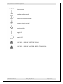
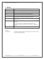
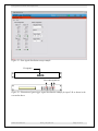
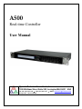
A500
Real-time Controller
User Manual
Pyramid Technical Consultants, Inc.
1050 Waltham Street Suite 200, Lexington MA 02421 USA
US: TEL: (781) 402 1700 ♦ FAX: (781) 402-1750 ♦ EMAIL: [email protected]
Europe: TEL: +44 1273 493590
PSI System Controls and Diagnostics
1 Contents
Safety Information ......................................................................................................................................................5
Models...........................................................................................................................................................................7
Scope of Supply............................................................................................................................................................8
Optional Items .............................................................................................................................................................9
Power supplies..........................................................................................................................................................9
Data cables ...............................................................................................................................................................9
Signal cables.............................................................................................................................................................9
Ancillary devices.......................................................................................................................................................9
Intended Use and Key Features ...............................................................................................................................10
Intended Use ...........................................................................................................................................................10
Key Features...........................................................................................................................................................10
Specification ...............................................................................................................................................................11
Installation .................................................................................................................................................................21
Mounting.................................................................................................................................................................21
Grounding and power supply .................................................................................................................................21
System connections .................................................................................................................................................22
Network connection ................................................................................................................................................24
IP address assignment ............................................................................................................................................25
Getting Started using the PSI Diagnostic Program................................................................................................28
Installing and running the PSI Diagnostic Program..............................................................................................28
Functional overview ..................................................................................................................................................31
Cell controller.........................................................................................................................................................31
A500 User Manual
A500_UM_090115
Page 2 of 61
PSI System Controls and Diagnostics
Expansion ...............................................................................................................................................................32
State machine..........................................................................................................................................................33
Connectors .................................................................................................................................................................36
Front panel connectors...........................................................................................................................................36
Optical gate input...............................................................................................................................................36
Additional fiber-optic ports................................................................................................................................36
Optional gate inputs ...........................................................................................................................................37
Optional fast scaler inputs..................................................................................................................................37
Rear panel connectors ............................................................................................................................................37
Power input ........................................................................................................................................................37
Ground lug .........................................................................................................................................................37
EtherNet communications..................................................................................................................................38
Controls and Indicators ............................................................................................................................................39
Front panel controls ...............................................................................................................................................39
Rear panel controls.................................................................................................................................................39
Reset button .......................................................................................................................................................39
IP address switches ............................................................................................................................................39
Front panel indicators ............................................................................................................................................40
LCD ...................................................................................................................................................................40
Rear panel indicators .............................................................................................................................................40
+24 V .................................................................................................................................................................41
+5 V ...................................................................................................................................................................41
Status..................................................................................................................................................................41
10 / 100 ..............................................................................................................................................................41
Internal jumpers and switches .................................................................................................................................42
Jumpers...................................................................................................................................................................42
Watchdog switch.....................................................................................................................................................43
POST...........................................................................................................................................................................44
Gate Option Board ....................................................................................................................................................45
Overview .................................................................................................................................................................45
A500 User Manual
A500_UM_090115
Page 3 of 61
PSI System Controls and Diagnostics
Operation of the Gate Function Using the PTC Diagnostic...................................................................................45
Gate Counter Option Board .....................................................................................................................................47
Overview .................................................................................................................................................................47
Circuit description ..................................................................................................................................................47
Operation of the Counter Function Using the PTC Diagnostic .............................................................................48
Fault-finding ..............................................................................................................................................................52
Maintenance...............................................................................................................................................................55
Returns procedure.....................................................................................................................................................56
Support .......................................................................................................................................................................57
Hardware Versions....................................................................................................................................................58
Change history........................................................................................................................................................58
Ethernet Processor .................................................................................................................................................58
Firmware Compatibility ...........................................................................................................................................59
Declaration of Conformity........................................................................................................................................60
User Manual Revision History .................................................................................................................................61
A500 User Manual
A500_UM_090115
Page 4 of 61
PSI System Controls and Diagnostics
2 Safety Information
This unit is designed for compliance with harmonized electrical safety standard EN610101:2000. It must be used in accordance with its specifications and operating instructions.
Operators of the unit are expected to be qualified personnel who are aware of electrical safety
issues. The customer’s Responsible Body, as defined in the standard, must ensure that operators
are provided with the appropriate equipment and training.
The unit is designed to support devices making measurements in Measurement Category I as
defined in the standard. It may also make such measurements directly, depending upon I/O
options that are installed.
The unit must not be operated unless correctly assembled in its case. Only Service Personnel, as
defined in EN61010-1, should attempt to work on the disassembled unit, and then only under
specific instruction from Pyramid Technical Consultants.
The unit is designed to operate from +24VDC power, with a maximum current requirement of
500mA. A suitably rated power supply module is available as an option. Users who make their
own power provision should ensure that the supply cannot source more than 2000mA.
A safety ground must be securely connected to the ground lug on the case.
Some of the following symbols may be displayed on the unit, and have the indicated meanings.
A500 User Manual
A500_UM_090115
Page 5 of 61
PSI System Controls and Diagnostics
Direct current
Earth (ground) terminal
Protective conductor terminal
Frame or chassis terminal
Equipotentiality
Supply ON
Supply OFF
CAUTION – RISK OF ELECTRIC SHOCK
CAUTION – RISK OF DANGER – REFER TO MANUAL
A500 User Manual
A500_UM_090115
Page 6 of 61
PSI System Controls and Diagnostics
3 Models
A500
Realtime controller with five fiber optic loop ports.
-R5T5
Add mezzanine board with five additional fiber optic ports.
-R10
Add mezzanine board with ten fiber optic receivers.
-T10
Add mezzanine board with ten fiber optic transmitters.
-G
Add gate input board with four independent gate inputs.
-GC
Add gate/counter board with four independent gate inputs and ten fast
counter inputs.
-A30
High-throughput A30 Ethernet processor replaces standard RCM3200
processor.
Note: The A30 became the standard Ethernet processor from
November 2008 onwards, and on all revision 3 A500s. Upgrades are
available.
Example:
A500-R5T5-GC
A500 User Manual
A500 with five additional fiber optic loop ports (for a total of ten ports)
and a gate/counter input board.
A500_UM_090115
Page 7 of 61
PSI System Controls and Diagnostics
4 Scope of Supply
A500 model as specified in your order, including mezzanine fiber-optic boards and interface
boards as necessary.
The first three blocks (24 most significant bits) of the IP address can be specified at the time of
order, and the unit will be delivered with this preset. The default if no specification is made is
192.168.100.
USB memory stick containing:
User manual
PSI Diagnostic software guide
Software installation guide
PSI diagnostic software files
Optional items as specified in your order.
A500 User Manual
A500_UM_090115
Page 8 of 61
PSI System Controls and Diagnostics
5 Optional Items
5.1 Power supplies
PSU24-45-1. +24 VDC 1.88 A PSU (100-250 VAC, 50-60 Hz, IEC C14 3-pin plug receptacle)
with output lead terminated in 2.1mm threaded jack.
PSU24-36-1. +24 VDC 1.5 A PSU (100-250 VAC, 50-60 Hz, IEC C8 2-pin plug receptacle)
with output lead terminated in 2.1mm threaded jack.
PD-8. +24 VDC power distribution unit, 100W, 100-250 VAC, 50-60 Hz IEC C14 3-pin plug
receptacle mains input, eight independent +24 VDC outputs on 2.1mm threaded socket.
5.2 Data cables
CAT5e eight conductor Ethernet cable, RJ45 terminated, 3m.
CAT5e eight conductor Ethernet cable, RJ45 terminated, crossover, 3m.
Custom lengths available upon request.
Fiber-optic cable, 1 mm plastic, ST terminated, 3 m.
Fiber-optic cable, 200 µm silica, ST terminated, 3 m.
Custom lengths available upon request.
5.3 Signal cables
Coax 50 ohm Lemo 00 terminated both ends, 2m.
5.4 Ancillary devices
X14, one to four optical trigger fanout device..
A500 User Manual
A500_UM_090115
Page 9 of 61
PSI System Controls and Diagnostics
6 Intended Use and Key Features
6.1 Intended Use
The A500 is intended for use in association with devices from the Pyramid Technical
Consultants, Inc. PSI family. These in their turn may be used to control other equipment such as
power supplies, measurement devices and so on, or they may make measurements directly.
Certain I/O board options can be installed in the A500 which can make direct measurements. An
example is the –GC gate counter board option.
The A500 has design features which make it tolerant of electrically noisy environments, but the
place of use is otherwise assumed to be clean and sheltered, for example a laboratory or light
industrial environment. The unit may be used stand-alone (with suitable I/O board options), or
networked with other devices and integrated into a larger system. Users are assumed to be
experienced in the general use of precision electronic circuits for sensitive measurements, and to
be aware of the dangers that can arise in high-voltage circuits.
6.2 Key Features
Real-time controller dedicated and optimized for the control of multiple devices over fiber-optic
loops.
Five loop ports, expandable to ten loops, each with up to 15 devices.
A500 to A500 communication capability via fiber-optic.
Host communications via 10/100 base T Ethernet, UDP or TCP/IP protocols.
Auto MDIX support (rev 3 hardware, or rev 2 hardware updated with the A30 Ethernet
processor)
I/O expansion ports for integration application-specific I/O boards.
Downloadable application code for both A500 and devices on fiber-optic loops.
Highly-optimized real-time operating system to provide genuine real-time response and
deterministic operation of connected devices.
A500 User Manual
A500_UM_090115
Page 10 of 61
PSI System Controls and Diagnostics
7 Specification
Processor
ADSP 21160 high performance 32 bit floating point SHARC
processor
Processor clock
80 MHz
External bus
20 MHz
Floating point speed
480 MFlops peak, 320 Mflops sustained (FIR algorithm)
On-chip memory
4 Mb x1 for program and data (max 87Kb x48 program or 128Kb
x32 data)
Operating system
Analog Devices VDK real time
Development environment
Analog Devices Visual DSP C++ version 4.5
External SRAM
8 Mb x 32, zero wait
NVR
512 kb x 8 battery-backed RAM
Program memory
4 Mb x 16 flash
Bootloader memory
512 kb x 8 demountable flash (MW29W040B PLCC)
I/O ports
Two internal isolated serial / parallel ports for expansion boards
Display
2 x 40 character LCD
Host communications
10 /100 Base T Ethernet
UDP and TCP/IP protocols
Loop communications
Five fiber optic TX/RX ports (10 Mbit/sec)
Power input
+24 VDC (+/-2 V), 500 mA.
A500 User Manual
A500_UM_090115
Page 11 of 61
PSI System Controls and Diagnostics
Case
1U 19” rack mounting chassis. Stainless steel with aluminium
front panel.
Case protection rating
The case is designed to rating IP43 (protected against solid
objects greater than 1mm in size, protected against spraying
water).
Weight
2.0 kg (4.4 lb)
Operating environment
0 to 35 C (15 to 25 C recommended to reduce drift and offset)
< 70% humidity, non-condensing
vibration < 0.1g all axes (1 to 1000Hz)
Shipping and storage
environment
-10 to 50C
< 80% humidity, non-condensing
vibration < 2 g all axes, 1 to 1000 Hz
Dimensions
(see figures 1 to 8).
Fiber optic expansion options
-R5T5
Additional five fiber optic TX/RX ports (10 Mbit/sec)
-R10
Ten fiber-optic receiver (RX) inputs (10 Mbit/sec)
-T10
Ten fiber-optic transmitter (TX) outputs (10 Mbit/sec)
Gate and counter input options
Gate input signals
Four independent 50 ohm terminated gate signal inputs (-G
option)
TTL levels
Counter inputs
Ten independent scaler inputs, 50 ohm terminated (-GC option,
with gate inputs).
Double height NIM pulses, -32 mA (-1.6 V in 50 ohms)
Smallest detectable pulse height -0.45 V
Maximum pulse rate 100 MHz
Minimum detectable pulse width 5 nsec
Minimum pulse pair resolution 10 nsec
A500 User Manual
A500_UM_090115
Page 12 of 61
PSI System Controls and Diagnostics
LCD DISPLAY
43.7
(1U)
482.6
(19")
+24VDC
POWER IN
FIBER-OPTIC TX (light gray)
FIBER-OPTIC RX (dark gray)
ETHERNET
ADDRESS SELECTOR SWITCHES (3)
RESET
STATUS LEDs
M4 GROUND LUG
Figure 1. A500 chassis front and rear panels. Five fiber-optic loop ports (rx / tx pairs).
Dimensions mm.
A500 User Manual
A500_UM_090115
Page 13 of 61
PSI System Controls and Diagnostics
448.0
TOP
9.2
482.6
(19")
221.0
247.2
3.0
43.7
(1U)
42.6
Figure 2. A500 case side and plan views. Dimensions mm.
A500 User Manual
A500_UM_090115
Page 14 of 61
PSI System Controls and Diagnostics
FIBER-OPTIC RXTX OPTIONS
LCD DISPLAY
43.7
(1U)
482.6
(19")
+24VDC
POWER IN
FIBER-OPTIC TX (light gray)
FIBER-OPTIC RX (dark gray)
ETHERNET
ADDRESS SELECTOR SWITCHES (3)
RESET
STATUS LEDs
M4 GROUND LUG
Figure 3. A500-R5T5 chassis front and rear panels. Five fiber-optic loop ports (rx / tx pairs).
Ten additional fiber-optic channels which can be five rx-tx pairs (-R5T5 option), ten rx (-R10
option or ten tx (-T10 option). Dimensions mm.
A500 User Manual
A500_UM_090115
Page 15 of 61
PSI System Controls and Diagnostics
448.0
TOP
9.2
482.6
(19")
221.0
247.2
3.0
43.7
(1U)
42.6
Figure 4. A500-R5T5 case side and plan views. Dimensions mm.
A500 User Manual
A500_UM_090115
Page 16 of 61
PSI System Controls and Diagnostics
FIBER-OPTIC TX/RX OPTIONS
LCD DISPLAY
482.6
(19")
+24VDC
POWER IN
FIBER-OPTIC TX (light gray)
FIBER-OPTIC RX (dark gray)
ETHERNET
ADDRESS SELECTOR SWITCHES (3)
RESET
GATE CONNECTORS (4)
STATUS LEDs
M4 GROUND LUG
Figure 5. A500-R5T5-G chassis front and rear panels. Five fiber-optic loop ports (rx / tx
pairs). Ten additional fiber-optic channels which can be five rx-tx pairs (-R5T5 option), ten rx (R10 option or ten tx (-T10 option). Four gate inputs. Dimensions mm.
A500 User Manual
A500_UM_090115
Page 17 of 61
PSI System Controls and Diagnostics
448.0
TOP
9.2
482.6
(19")
221.0
247.2
3.0
43.7
(1U)
42.6
Figure 6. A500-R5T5-G case side and plan views. Dimensions mm.
A500 User Manual
A500_UM_090115
Page 18 of 61
PSI System Controls and Diagnostics
FIBER-OPTIC TX/RX OPTIONS
LCD DISPLAY
43.7
(1U)
482.6
(19")
+24VDC
POWER IN
FIBER-OPTIC TX (light gray)
FIBER-OPTIC RX (dark gray)
ETHERNET
ADDRESS SELECTOR SWITCHES (3)
RESET
COUNTER CONNECTORS (10)
GATE CONNECTORS (4)
STATUS LEDs
M4 GROUND LUG
Figure 7. A500-R5T5-GC chassis front and rear panels. Five fiber-optic loop ports (rx / tx
pairs). Ten additional fiber-optic channels which can be five rx-tx pairs (-R5T5 option), ten rx (R10 option or ten tx (-T10 option). Four gate inputs and ten fast scaler inputs. Dimensions
mm.
A500 User Manual
A500_UM_090115
Page 19 of 61
PSI System Controls and Diagnostics
448.0
TOP
9.2
482.6
(19")
221.0
247.2
3.0
43.7
(1U)
42.6
Figure 8. A500-R5T5-GC case side and plan views. Dimensions mm.
A500 User Manual
A500_UM_090115
Page 20 of 61
PSI System Controls and Diagnostics
8 Installation
8.1 Mounting
The A500 is intended for mounting in a 19” rack. It can be used free-standing on a table-top if
required.
The mounting position should allow sufficient access to connectors and cable bend radii. Leave
100mm clearance at either end for mating connectors and cable radii. The cooling fan must not
be obstructed.
8.2 Grounding and power supply
A secure connection should be made using a ring lug, from the M4 ground lug to local chassis
potential. +24 VDC power should be provided from a suitably-rated power supply with the
following minimum performance:
Output voltage
+24 +/- 0.5 VDC
Output current
500 mA minimum, 2000 mA maximum
Ripple and noise
< 100 mV pk-pk, 1 Hz to 1 MHz
Line regulation
< 240 mV
The A500 includes an internal automatically re-setting PTC fuse rated at 1.1 A. However the
external supply should in no circumstances be rated higher than the A500 connector limit of 5 A,
and a maximum of 2.0 A is recommended.
A500 User Manual
A500_UM_090115
Page 21 of 61
PSI System Controls and Diagnostics
8.3 System connection
The A500 can form the heart of signal acquisition and control systems with a wide variety of
configurations. Refer to the document PSI_OV_071023 “Versatile Communications and Control
for Scientific and Engineering Applications” for more details of possible connection
arrangements.
Figure 9 shows one possible configuration installation in schematic form, for a relatively small
system of seven devices on two loops. In this example hardware gate signals are distributed by
the A500 to some of the devices, using the gate interface board.
Dev
Gate in
Dev
Gate out to device
Dev
Communication loop
A500
Network
Gate out to device
Dev
+24V in
Dev
Communication
loop
Dev
Dev
Figure 9. Schematic example A500 installation showing gate distribution
The fiber-optic links can be up to hundreds of meters long. The cables terminations and the
transmitter / receiver ports on the A500 and the front-end devices are color-coded to aid
connection.
Transmitter
Receiver
Light gray
Dark gray
To make the connections, firstly ensure that the key on the free connector aligns with the keyway
at the top of the socket on the A500. Slide home and then push gently against the spring
A500 User Manual
A500_UM_090115
Page 22 of 61
PSI System Controls and Diagnostics
pressure before rotating the bayonet collar. Do not force the connector. If it does not appear to
be inserting correctly, the key is probably misaligned.
There is no constraint on the order in which devices are connected on the communication loops,
or which loop ports on the A500 they are connected to. The Pyramid Technical Consultants, Inc.
PSI Diagnostic host software, and any user software that uses Pyramid DLLs will search all loop
ports for devices. The only thing you must do is ensure that each loop is completed back to the
receiver on the A500, and that each device on a given loop has a unique address switch setting (1
to 15).
The number of loops can be up to five or ten, depending upon the A500 configuration, and each
loop can have up to 15 devices. The more devices that are attached to the loop, the more the data
bandwidth has to be shared between the devices, so in general it is useful to populate the five
loops evenly if data rate is important. The type of front-end device affects the amount of data it
generates, so this must also be taken into consideration too.
Up to five (-R5T5 option) or ten (-T10 option) direct gate output lines can be derived from up to
four gate input signals. If the devices to be gated or triggered are remote from the A500, and if
they all require the same gate/trigger signal, it may be more convenient for cabling to run a
single fiber optic over the long cable run, then fan out the signal near the target devices. The
Pyramid Technical Consultants, Inc. X14 device provides a one to four fanout for this purpose.
Figure 10 illustrates some other system architecture options. One loop of six devices is shown,
but each of these devices has a fast data stream output direct to the A500. This capability is
provided by the D100 pulse processing device for example. Up to ten devices of this type can be
attached to one A500 through the ten channel fiber-optic receiver board (option -10R). Slower
data such as configuration parameters is passed over the communication loop. A second loop
port is used to communicate peer-to-peer with another A500.
A500 User Manual
A500_UM_090115
Page 23 of 61
PSI System Controls and Diagnostics
Dev
Dev
Direct data streams
Dev
A500
Network
Dev
Communication
loop
Dev
+24V in
Link to another
A500
Dev
Figure 10. Schematic example A500 installation showing fast data stream links and peer-topeer connection to another A500.
8.4 Network connection
The simplest possible network is a direct connection to a PC Ethernet port. This arrangement is
used in the initial assignment of the IP network address.
If your A500 has the RCM3200 Ethernet processor, you must use an RJ-45 to RJ-45 crossover
cable (also called a CAT5e crossover cable). If your A500 has the A30 Ethernet processor, then
you can use a crossover or non-crossover cable, because the A30 supports Auto MDIX.
A500
Crossover cable
+24V in
Figure 11. Direct connection to a PC
Generally you will want to connect the A500 to a larger network. In this case you will require a
Ethernet hub or switch. The connection from the A500 to the hub or switch now requires a nonA500 User Manual
A500_UM_090115
Page 24 of 61
PSI System Controls and Diagnostics
crossover RJ-45 to RJ-45 cable, also called a CAT5e patch cable. Again, the A30 Ethernet
processor will connect with either type of cable.
Network hub
A500
Patch cables
+24V in
Figure 12. Connection to a local network via a hub
8.5 IP address assignment
Every device connected to a network must have an IP address assigned to it that allows network
hubs and routers to route data packets to the correct destination. Every Ethernet device such as
the A500 also has a unique MAC ID, and the network servers maintain the cross-reference of IP
address to MAC ID. In office networks, the IP address is often assigned dynamically (“leased”)
by a DHCP server when the device is connected. The A500 is designed to work in stable
controls networks, however, and is therefore intended to work with fixed IP addressing.
An IP address has the format xxx.xxx.xxx.xxx where xxx is a decimal number from 0 to 255,
representing a thirty-two bit binary number. The address is divided into a local network portion
and overall internet portion by a network mask. For example a mask of 255.255.255.0 divides
the network “universe” into two parts. The local network, exposed by zeroes in the eight lowest
bits of the mask, has 256 addresses. The highest is used for broadcast messages, and the lowest
to identify the network. One other address is often reserved for a gateway. Any data with an
address outside the range exposed by the mask is routed to the gateway, if it is defined, for
routing out onto the internet.
The A500 is shipped by default with local network address 192.168.100.xxx. The final three
numbers that specify the address within the local network are given by the setting of the three
rear panel switches, in the range 001 to 255. You can specify a different local network address
at the time of order, and the unit will be delivered with this preset for you.
However, the A500 can be assigned any address using the following procedure:
1) Set the rear panel address switches to 888.
A500 User Manual
A500_UM_090115
Page 25 of 61
PSI System Controls and Diagnostics
2) Connect direct to a host PC with a crossover cable. Power up the A500. At the end of the
POST you should see the IP address displayed as 192.168.100.100, and the unit will remain in
the boot state.
3) The unit is now in a special initialization state where it will respond to a message on
192.168.100.100. The host PC should be fixed at non-conflicting address in the same range, for
example 192.168.100.1.
4) Confirm that you can ping the A500 on address 192.168.100.100.
5) Using the Pyramid Technical Consultants, Inc. configuration utility program, or your own
software that can use the appropriate DLL function call, send the required setting for the first
three blocks of the IP address (the local network address) which will be stored in flash memory
on the A500.
6) Power down the A500 and set the three address switches to the required number for the last
block of the IP address (which must be in the range 001 to 255). The switches read from left
(MSD) to right (LSD).
7) Whenever the A500 boots up it will now take the IP address comprising 24 bits given by the
downloaded number followed by 8 bits given by the switch setting. The IP address is shown on
the A500 LCD during the Power-On-Self –Test (POST) during the boot sequence:
Testing Ethernet…
V3.2 192.168.100.127
A very common local network address range is 192.168.xxx.xxx., which is reserved to local
networks and not permitted on the general internet. So for example, you could download
192.168.2 for the first blocks corresponding to your local network, and then use the switches to
select one of 254 available addresses for the A500. If in doubt, you can confirm the IP address
has taken effect by sending the “ping” command from a console window on the PC.
A500 User Manual
A500_UM_090115
Page 26 of 61
PSI System Controls and Diagnostics
Figure 13. Testing a network connection with ping.
It is also possible to use the special switch setting 999 in the above procedure. With this setting
the IP address is still forced to 192.168.100.100, but the A500 proceeds to boot any installed
application code after the POST. However, if there is a large version incompatibility between
the embedded application and the PSI Diagnostic host, the host may not be able to communicate
to allow a new code download. The boot state, however, as accessed using the 888 setting,
should be accessible from all Diagnostic host versions.
A500 User Manual
A500_UM_090115
Page 27 of 61
PSI System Controls and Diagnostics
9 Getting Started using the PSI Diagnostic Host Program
The PSI Diagnostic is a stand-alone program which allows you to read, graph and log data from
various front-end devices, and set all the important acquisition control parameters. For some
applications it may be adequate for all of your data acquisition needs.
9.1 Installing and running the PSI Diagnostic Program
Your A500 was shipped with a USB memory stick with the installation files you need. We
recommend that you copy the files into a directory on your host PC. Check the Pyramid
Technical Consultants, Inc. web site at www.ptcusa.com for the latest versions.
The program runs under the Microsoft Windows operating system with the 2.0 .NET framework.
This has to be installed before the PSI Diagnostic. Most new PCs have .NET already installed.
It can be downloaded from the Microsoft web site at no charge, or there is an installation file
included on the USB memory stick.
Install the PSI Diagnostic by running the PTCDiagnosticSetup.msi installer, and following the
screen prompts. Once the program has installed, you can run it at once. It will allow you to
connect to the A500, and, depending upon your interface setup, multiple additional devices at the
same time. The Diagnostic uses the concepts of ports and loops to organize the connected
devices. A port is a communications channel from your PC, such as a COM port, a USB port or
and Ethernet port. In the case of the A500, the connection to the PC is via Ethernet. Each port
can be a channel to one or more loops, and each loop may contain up to 15 devices.
1) Inspect the unit carefully to ensure there is no evidence of shipping damage. If there appears
to be damage, or you are in doubt, contact your supplier before proceeding.
2) Connect 24 V DC power but no other connections. The rear panel +24 V and +5 V power
LEDs should illuminate when the power is applied.
4) Start the PSI Diagnostic. It will search the available communication channels and present a
search list. If the list does not already include the IP address of your A500, enter this into the
edit box followed by :100 for the network port (for example 192.168.100.100:100), and click
“Add”. The network port is fixed at :100 in A500s. Future versions may lift this restriction in
case there are conflicts on particular networks.
A500 User Manual
A500_UM_090115
Page 28 of 61
PSI System Controls and Diagnostics
Figure 14. PSI Diagnostic Search Utility
Check the box next to this address to ensure it is included in the search. Click “start” and the
program will search for loops and devices on all checked options.
The LAN Broadcast search uses information from the PC operating system to search for A500s
over the whole of your local network. This will generally take longer than going directly to a
known IP address.
A few seconds after you click the “Start” button, the program should find the A500 (plus any
connected front-end devices). Expanding the tree in the System window will reveal the devices
that were discovered. Clicking on any discovered device will open its specific window.
A500 User Manual
A500_UM_090115
Page 29 of 61
PSI System Controls and Diagnostics
Figure 15. Diagnostic display after completion of a search. An A500 at 192.168.2.3 with
various devices on loops 1,2,3 was found.
A500 User Manual
A500_UM_090115
Page 30 of 61
PSI System Controls and Diagnostics
10 Functional overview
10.1 Cell controller
The core of the A500 is the cell controller board. Together with a dedicated processor for the
Ethernet port and an LCD display, this constitutes a high-performance real-time controller that
can service five fiber-optic loops with up to fifteen devices per loop. A large, fast FPGA handles
all communications, and a high speed floating-point digital signal processor handles data
manipulation. Only the services necessary for the application run on the A500, in contrast to the
typical situation on a PC, so that a fast, deterministic system can be implemented for real-time
data handling.
Cell controller board
24VDC
in
Network
Communication
Fibre-optic loops
DC-DC
converters
Ethernet
processor
SRAM
FPGA
App code
Flash
Boot
Flash
NVR
Sharc DSP
LCD
I/O Port
I/O Port
Figure 16. A500 schematic architecture
Bootloader code stored on a socketed flash memory device is executed on power-up. This
executes a power-on self-test (POST) of the whole device. The results are displayed on the
LCD. The A500 then waits for a message from the host which can either be a command to
download new application code, or to boot from a selection of one or more resident application
A500 User Manual
A500_UM_090115
Page 31 of 61
PSI System Controls and Diagnostics
programs. The application programs are stored in the application code flash, and are loaded into
SRAM for execution. Non-volatile RAM (NVR) is available to persist application data, for
example in event of a power failure.
Ethernet port
Reset
button
I/O port
LCD connector
+24 V
in
LEDs
I/O port
Watchdog
switch
Fiber-optic
comms ports
JPR2
Boot flash
RX
TX
Mezzanine fiber-optic board connector
Figure 17. A500 cell controller board with RCM3200 Ethernet processor
+24 V input power is converted to the various voltage rails needed by the board by DC-DC
converters. The Ethernet processor board handles all aspects of the network protocol.
10.2 Expansion
A pair of connectors allow a mezzanine board containing ten more fiber-optic devices to be
fitted for the –R5T5, -R10 and –T10 options. Two I/O ports isolated by magnetic couplers allow
application-specific I/O boards to be connected within the A500 chassis.
A500 User Manual
A500_UM_090115
Page 32 of 61
PSI System Controls and Diagnostics
Cell controller board
24VDC
in
Network
Communication
Fibre-optic loops
DC-DC
converters
Ethernet
processor
SRAM
FPGA
App code
Flash
Boot
Flash
NVR
Sharc DSP
LCD
I/O Port
I/O Port
Interface board
Gate input (4)
FPGA
Counter input (10)
Figure 18. A500-R5T5-GC schematic architecture
10.3 State machine
The A500 obeys a state machine as shown in figure 19.
A500 User Manual
A500_UM_090115
Page 33 of 61
PSI System Controls and Diagnostics
Reset
POST
Error
found
Fatal
Success
Boot
Failed
A500:LoadProgram()
Error
Load program
Success
Go to Idle
command
Action
Started
Idle
Error
detected
Run
Complete
Figure 19. A500 software base state machine
The present state is displayed on the bottom left of the A500 display (see section 12.3.1). The
states are described below:
State
Description
BOOT
POST successful, ready to accept either boot program or code download
command.
CONN
Application program successfully loaded, but devices attached to the FO
loops have not been successfully connected.
IDLE
All devices are connected and ready to accept commands.
RUN
Running an application command, pass-through not possible but other
commands may be accepted.
ERROR
Error detected while in the RUN state.
FATAL
Fatal hardware detected by POST, communication possible with the A500
device if the Ethernet did not fail, but no other functions allowed.
After a successful POST the boot-loader enters the BOOT state and automatically downloads the
host application stored in the FLASH program memory. Once the program is successfully
booted the state transitions to the Conn state, waiting for devices to be discovered by the host
and connected. A special Ethernet switch combination is provided that will cause the A500 to
stop at the Boot state. Setting the three switches each to 8 will enable this feature, and establish
the default Ethernet address 192.168.100.100.
A500 User Manual
A500_UM_090115
Page 34 of 61
PSI System Controls and Diagnostics
An application program can be downloaded in either the Boot state or the Idle state using the
WIN32DLL command A500::DownloadApplication(). Applications can also be loaded from the
PTC A500 Diagnostic Setup page.
A500 User Manual
A500_UM_090115
Page 35 of 61
PSI System Controls and Diagnostics
11 Connectors
11.1 Front panel connectors
11.1.1 Communication loops
ST socket bayonet female for five communication loops. To mate with ST terminated fiber
optic.
RX TX
Loop 1
RX TX
Loop 2
RX TX
Loop 3
RX TX
Loop 4
RX TX
Loop 5
11.1.2 Additional fiber-optic ports
Optional upper row ST socket female bayonets on mezzanine board for expansion options. To
mate with ST terminated fiber optic.
A500-R5T5
RX TX
RX TX
RX TX
RX TX
TX RX
Five additional fiber-optic transmitter – receiver pairs that can be configured as five additional
communication loops, or for individual special functions.
In the A500-R5T5-G and A500-R5T5-GC versions the extra five transmitters (TX) are used for
outgoing trigger or gate signals. They can be assigned arbitrarily to incoming TTL signals on
the four rear panel TTL gate inputs.
A500-R10
RX RX
RX RX
RX RX
RX RX
RX RX
Ten additional fiber-optic receivers for fast data stream input or individual special functions.
A500-T10
A500 User Manual
A500_UM_090115
Page 36 of 61
PSI System Controls and Diagnostics
TX TX
TX TX
TX TX
TX TX
TX TX
Ten additional fiber-optic transmitters for individual special functions.
11.1.3 Optional gate inputs
Four Lemo 00 coax sockets for gate input signals. TTL levels, 50 ohm terminated. Center pin
signal, screen ground. -G and –GC options only.
1
2
3
4
11.1.4 Optional fast scaler inputs
Ten Lemo 00 coax sockets for gate input signals, 50 ohm terminated.. Double amplitude NIM
levels, -32 mA to give -1.6 V in 50 ohms. Minimum signal amplitude to Center pin signal,
screen ground. –GC option only.
1
2
3
4
5
6
7
8
9
10
11.2 Rear panel connectors
11.2.1 Power input
2.1 mm threaded jack. To mate with Switchcraft S761K or equivalent
Center pin: +24VDC
Outer: 0V
11.2.2 Ground lug
M4 threaded stud. To mate with M4 ring lug.
A500 User Manual
A500_UM_090115
Page 37 of 61
PSI System Controls and Diagnostics
11.2.3 Ethernet communications
RJ-45 female. To mate with RJ-45 male on standard CAT5 eight-way twisted pair network
cable.
1
Pin
1
2
3
4
5
6
7
8
8
ID
TX_D1+
TX_D1RX_D2+
BI_D3+
BI_D3RX_D2BI_D4+
BI_D4-
Function
Transmit data +
Transmit data Receive data +
Bidirectional data +
Bidirectional data Receive data Bidirectional data +
Bidirectional data -
Note
Not used by A500
Not used by A500
Not used by A500
Not used by A500
Patch cable
White / orange
Orange (/ white)
White / orange
Blue (/ white)
White / blue
Green (/ white)
White / brown
Brown (/ white)
Crossover cable
White / green
Green (/ white)
White / orange
Blue (/ white)
White / blue
Orange (/ white)
White / brown
Brown (/ white)
The A30 Ethernet processor supports Auto MDIX, so the assignment of transmit and receive is
altered as necessary when a connection is made.
A500 User Manual
A500_UM_090115
Page 38 of 61
PSI System Controls and Diagnostics
12 Controls and Indicators
12.1 Front panel controls
None.
12.2 Rear panel controls
ADDRESS SELECTOR SWITCHES (3)
RESET
Figure 20. Portion of the rear panel showing controls
12.2.1 Reset button
Momentary push-button to reset the cell controller board FPGA and DSP. The A500 will reboot
when the switch is pressed.
12.2.2 IP address selector switches
Three ten-position rotary switch setting the last three digits of the IP address. Digits indicate the
last eight bits of the full IP address. Allowed values for IP addresses are 001 to 254. The
switches are read at boot up only.
Two special codes are available outside the normal IP address range, which cause special bootup
behaviour:
888
The A500 will go through the POST, but then halts in the boot state. The IP
address is forced to 192.168.100.100.
999
The A500 will go through the POST, and launch the installed firmware. The IP
address is forced to 192.168.100.100.
A500 User Manual
A500_UM_090115
Page 39 of 61
PSI System Controls and Diagnostics
12.3 Front panel indicators
12.3.1 LCD
2 x 40 character alphanumeric display for showing A500 status, loop status, and power-up selftest (POST) information. See section 14 for details of the POST displays.
The standard display format following boot is shown in figure 21.
A 5 0 0
I d l e
V 2. 8
< * * >
1*
1 2
2*
0 2
3*
0 4
4*
0 1
5*
0 3
Figure 21. LCD display format for A500
The top left area shows the device (A500) and the installed application firmware version.
The lower left area shows the current device state (boot, conn(ected), or idle).
The flashing asterisk on the left of the <**> shows that the A500 is operating normally; the one
on the right indicates that the Ethernet connection to the host is made and communications are in
progress.
The fiber-optic loops are indicated by the numerals 1 to 5 in the top row. Flashing asterisks
indicate that the loop is active. The number below the loop is the number of devices that are
being serviced on the loop.
The display for the –R5T5 option shows loops from 1 to A. The –R10 and –T10 options show
the ten devices (rx and tx respectively), with a flashing asterisk below to illustrate activity, such
as an incoming data stream for the A500-R10.
A 5 0 0
I d l e
V 2. 8
< * * >
1*
1 2
2*
0 2
3*
0 4
4*
0 0
5*
0 0
r x 1 2 3 4 5 6 7 8 9A
*
* * *
* *
*
Figure 22. LCD display format for –R10 option
12.4 Rear panel indicators
A500 User Manual
A500_UM_090115
Page 40 of 61
PSI System Controls and Diagnostics
STATUS LEDs
+24 V
+5 V
STATUS
10 / 100
Figure 22. Portion of the rear panel showing indicators
12.4.1 +24 V
Green LED. Lights to indicate +24 VDC power is present.
12.4.2 +5 V
Green LED. Lights to indicate +5 VDC power is present.
12.4.3 Status
Green LED. Flashes to indicate FPGA has started normally and DSP is booted and running
normally.
12.4.4 10 / 100
Green LED. Lights to indicate Ethernet controller has slowed to 10 MB/s.
A500 User Manual
A500_UM_090115
Page 41 of 61
PSI System Controls and Diagnostics
13 Internal jumpers and switches
See figure 17 for the location of jumpers and switches on the cell controller board.
CAUTION
Internal jumpers and switches should not be altered without first consulting your supplier or
Pyramid Technical Consultants, Inc. Unpredictable operation may result.
13.1 Jumpers
Jumper bank 2 informs the A500 about various hardware options that may be installed. These
jumpers are normally factory-configured and should not be changed, and depend upon the
hardware revision of the A500 board.
A500 Hardware Rev 1
Link
0-2
3-4
Description when fitted
The type of application specific I/O board, if any, that is connected to I/O port #1.
Connect these links to form a binary number from 0-3.
0 [link none connected]
-no I/O board present
1 [link 0 connected]
-GC board connected
2 [link 1 connected]
-G board connected
The type of fiber-optic mezzanine board that is installed. Connect these links to
form a binary number from 0-1.
0 [none connected]
-no mezzanine board present
1 [link 3 connected]
-RX10 board present
2 [link 4 connected]
-R5T5 board present
3 [link 3-4 connected]
-TX10 board present
A500 Hardware Rev 2 and Rev 3
Link
0-2
3-5
Description when fitted
The type of application specific I/O board, if any, that is connected to I/O port #1
(channel B). Connect these links to form a binary number from 0-3. The currently
supported boards are:
0 [none connected]
-no I/O board present
1 [link 0 / B3 connected]
-GC board connected
2 [link 1 / B2 connected]
-G board connected
The type of application specific I/O board, if any, that is connected to I/O port #2
A500 User Manual
A500_UM_090115
Page 42 of 61
PSI System Controls and Diagnostics
(channel A). Connect these links to form a binary number from 0-3. The currently
supported boards are:
0 [none connected]
-no I/O board present
Note that the rev2 A500 autodetects the any fiber-optic mezzanine card that is installed, so
jumper settings are not required.
13.2 Watchdog switch
This switch should always be set to the ON position to enable the watchdog feature.
A500 User Manual
A500_UM_090115
Page 43 of 61
PSI System Controls and Diagnostics
14 POST
The boot-loader starts up the A500 by performing a Power On Self Test (POST), checking the
integrity of the A500. The results are displayed on the LCD. The following tests are performed
in sequence:
Device
Description
Display
Write the alphabet to the right hand portion of the display. The user can verify
that this occurs.
NVR
The battery-backed up non-volatile RAM is given a non-destructive test that
writes different patterns to each locations and verifies the write. Sequential
values are also written to make sure that the value stays written. No check of
the actual battery persistence is made, since this would require that the
controller be powered off.
SRAM
The external SRAM is checked by walking a bit through all memory
locations, and also by writing sequential values and verifying. This is a
destructive test, and all memory is set to 0 upon completion.
FLASH
The flash memory is tested first by examination of the factory sequence 0x20
and 0x17 that is found at location 0 of the FLASH. The reserved POST block
(63) is then used to write out a sequence of 0xAAAA, 0x5555, 0x0000, and
0xFFFF and an ascending sequence and read back. This is a destructive test,
but is done on only the reserved segment.
Watchdog
The watchdog is tested by first writing a special value to the NVR, then by
holding off the watchdog tickle so that the device resets. If it resets, the bootloader knows to vector right back to where it left off, seamlessly testing the
watchdog. If it does not reset after a time-out, a POST error is flagged.
Timer
The FPGA timer is tested by measuring the timer versus the DSP timer for 1
second.
Ethernet
A special test message is transmitted to the RCM3200 or A30 Ethernet
processor and read back to determine if the Ethernet board is operating
properly. The IP address of the A500 is displayed on the LCD. No test is
made to determine if host communications are working.
A500 User Manual
A500_UM_090115
Page 44 of 61
PSI System Controls and Diagnostics
15 Gate Option Board
15.1 Overview
The gate option board is a full-size I/O board which connects to both expansion port connectors
of the cell controller board. It is logically connected on port 1. JPR B2 on bank 2 on the cell
controller is fitted to identify the board.
The gate board provides four independent inputs for gate (or trigger) signals on Lemo coaxial
connectors. The logic levels are TTL and the inputs have 50 ohm impedance.
The incoming gate/trigger signals are routed and used according to a software-selectable
configuration. Generally the –G option will be combined with the –R5T5 fiber optic mezzanine
card option, which provides five additional fiber optic transmitters. Each of the TTL gate inputs
can be directed to any or all of the transmitters. These fiber optic signals are then typically taken
to the gate inputs of triggerable devices connected to the A500 communication loops. If the
devices are remote from the A500, and if they all require the same trigger, then it can be
convenient for cabling to take only a single trigger line from the A500 and use a trigger fanout
unit such as the X14, local to the devices.
In addition to driving fiber optic transmitters, any of the TTL inputs can be selected to be a
trigger for the counters in the gate-counter board (see next section 16). There are no constraints
on the permutations of input to fiber optic output and counter trigger mapping.
The latency for a signal to be passed from a TTL input to a fiber optic output is about 50 nsec.
The latency from the TTL input to the response of a fiber optic receiver in a remote device is
about 200 nsec, as a result of the rise times of the fiber optic transmitter and receivers. The
further time for the remote device to capture the required data will depend upon the details of its
particular measurement process, of course.
15.2 Operation of the Gate Function Using the PTC Diagnostic
The PSI Diagnostic host program allows you to try out the gate input features. Figure 23 shows
the setup tab where the gate/trigger distribution logic can be set up. In the example shown,
trigger signals arriving at the gate input 1 (also labeled A) are used to drive the first fiber optic
transmitter only; and gate input 2/B is used to drive transmitters 2, 4 and 5 in parallel. Figure 24
shows the second situation graphically. You can in fact test the setup if you provide a DC level
at a particular input, as the selected output transmitters will illuminate in the visible (red light).
The Trigger LEDs on the setup screen also illuminate when a signal is seen on the corresponding
input.
A500 User Manual
A500_UM_090115
Page 45 of 61
PSI System Controls and Diagnostics
Figure 23. Gate signal distribution setup example.
TTL signal in
Fiber optic signals out
Figure 24. Illustration of gate/trigger signal distribution example for input 2/B, as shown in the
screenshot above.
A500 User Manual
A500_UM_090115
Page 46 of 61
PSI System Controls and Diagnostics
16 Gate-Counter Option Board
16.1 Overview
The gate-counter is a full-size I/O board which connects to both expansion port connectors of the
cell controller board. It is logically connected on port 1. JPR B3 on bank 2 on the cell controller
is fitted to identify the board.
The gate-counter provides the same function as the gate option board and adds a ten-channel
pulse scaler facility. The pulse inputs are designed to detect NIM-standard double height fast
logic pulses (-1.6 V, >= 5 nsec duration). The input impedance is 50 ohms, so the nominal input
drive current is 32 mA.
16.2 Circuit description
The incoming signals (negative going) are terminated in 50 ohms and sent to one input of a fast
comparator. The other input of the comparator is set to threshold voltage by a buffered voltage
divider. The nominal threshold setting is -0.45 V, and this is common to all ten inputs.
The comparator outputs are connected to a dedicated FPGA which provides ten parallel 32 bit
counters. This communicates with the cell controller over multiple serial interfaces. When the
cell controller asserts a control line, all ten counters are zeroed and start to acquire data. When
the selected integration time is reached, the gate-counter FPGA interrupts the cell controller DSP
which executes a readout sequence. The counter contents are copied and latched, and the
counters are reset. There is no interruption to the counting. The cell controller reads the counts
over the serial data lines in the background.
The minimum integration time is 100 µsec. There is no upper limit, but you must not risk
counter overflow, so a maximum of 60 sec is recommended. The maximum count is 2^32, or
about 4.3e9 counts. In general you should choose integration times that will give a few hundred
counts for typical anticipated rates, so as to achieve a reasonable compromise between time
resolution and counting statistics.
In any integration readout, there is a resolution of 5 individual counts. However no individual
counts are lost, so this quickly becomes negligible over multiple integrations. As an example,
say there was a constant input of 30 kHz, and 100 µsec integrations. The expected count in each
integration would thus be 3. The reported counts would be 0, 5, 5, 10, 15, 15, 20 etc. Generally
such low counts should be avoided, however, by using appropriate integration periods, because
the otherwise the counting statistics are poor.
A500 User Manual
A500_UM_090115
Page 47 of 61
PSI System Controls and Diagnostics
-5 V
Vref
Gnd
I/P 1
50R
Data out to
cell controller
FPGA
Data in from
cell controller
Control lines
I/P 10
Figure 24. Counter circuit simplified schematic
16.3 Operation of the Counter Function Using the PTC Diagnostic
The PSI Diagnostic host program allows you to try out the counter inputs. Figure 25 shows the
setup tab arranged so that the counters are triggered by a positive-going edge on gate input 3/C.
The counters will be read out 100 times in continuous succession, with individual integration
times of 1 msec.
A500 User Manual
A500_UM_090115
Page 48 of 61
PSI System Controls and Diagnostics
Figure 25. Example counter setup
The available trigger modes for the counters are:
Internal
Auto-run. The start event is generated internally by the A500 once the
“initiate” message is received. Readings continue until the defined
number of trigger points is reached, or the “abort” message is
received.
External Start
A rising (falling) edge on the gate input starts a predefined acquisition
sequence. Readings continue until the defined number of trigger
points is reached, or the “abort” message is received.
External Start-Stop
A rising (falling) edge on the gate input starts a predefined sequence
of integrations. Readings continue until either the programmed
number of integrations is complete, or the gate input falls (rises)
again, in which case the sequence terminates after the integration in
progress. Readings continue until the defined number of triggers is
reached, or the “abort” message is received.
The number of trigger points can be set to INFinite in which case the counting will continue
indefinitely, until halted by an Abort command from the host.
The data tab allows you to initiate and abort acquisitions, and view the counter contents. You
can display the values as the counts in each channel, or the rate in Hz in each channel.
A500 User Manual
A500_UM_090115
Page 49 of 61
PSI System Controls and Diagnostics
Figure 26. Counter data screen
Initiate
Set up the A500-R5T5-GC to acquire counts upon receiving a trigger,
using the parameters defined on the setup sub-tab. If the trigger mode
is Internal, acquisition will start immediately.
The measuring LED goes green when a measurement is in progress.
The triggering LED goes green when a trigger is in present.
Abort
Stops the acquisition sequence in progress
Cycle #
The number of times the Diagnostic will execute the programmed
acquisition sequence.
Integration number
The number of the integration in progress since the last initiate.
Time since start
Integration number x integration period
Channel n
The counts in channel n at the most recent read. Check the Display
Rate option to display in Hz.
Y-range
Vertical scaling of the graphic
X-time
Horizontal (time) resolution of the graphic and the data buffer.
A500 User Manual
A500_UM_090115
Page 50 of 61
PSI System Controls and Diagnostics
kB, buffer
The proportion of the Diagnostic data buffer that has been consumed
Clr
Clear the Diagnostic data buffer
File
Save the current data buffer contents to csv file. All ten channels are
recorded.
Couple
DC or AC coupling of the data as displayed (recorded data .
Generally DC coupling is appropriate, but AC coupling may be useful
if you are looking for changes in count rate against a large offset.
Mode
You can display the data as a strip chart or histogram. The strip chart
can also be displayed in differential mode (the difference between
successive readings is plotted).
Run
This control enables data recording by the Diagnostic. It does not
affect the acquisition at the A500 level.
A500 User Manual
A500_UM_090115
Page 51 of 61
PSI System Controls and Diagnostics
17 Fault-finding
Symptom
Possible Cause
Confirmation
Solution
No characters on the LCD on
power up
Unit failed to boot.
No communications possible,
status LED not blinking.
Power-cycle. If unit still does
not boot, contact your
supplier.
A500 runs normally, but no
LCD display
LCD failed or disconnected
Unable to establish Ethernet
connection.
Incorrect IP address.
Arrange service for the A500.
Unable to ping A500 at the
expected address.
Another device has the same
address.
Set correct IP address.
Ensure all devices in your
LAN have unique addresses.
Wrong type of network cable
(RCM3200 Ethernet processor
only).
Check cable – should be patch
cable for connection to a hub.
Use correct cable.
Unable to connect with a
direct PC to A500 link
Wrong type of network cable
(RCM3200 Ethernet processor
only).
Check cable – should be a
crossover cable for a direct
connection.
Use correct cable.
Unable to connect from the
PSI Diagnostic host.
Another instance of the
Diagnostic may already be
running on your network.
Run one host program only.
Looped devices not detected.
Fiber-optic cables
interchanged.
Check all TX and RX are
connected correctly.
Devices on loop have
incorrect mode switch
settings.
A500 User Manual
A500_UM_090115
Check comms status of
devices on the loop.
Page 52 of 61
Ensure all mode switches are
set to 0 for operation with
A500.
PSI System Controls and Diagnostics
Mezzanine fiber-optic card or
application I/O card not
functioning
Incorrect jumper settings on
cell controller card
No response to gate/trigger
inputs of gate option board
A500 is not set up to pass
signals through to fiber optic
outputs
Check configuration.
Signals unable to drive the
50R inputs to TTL threshold
Test with signal generator
with 50R output
No counts seen by gatecounter board
Ensure jumper settings are
correct.
Configure as required
Set another fiber optic output
to duplicate the required
outgoing trigger, and confirm
that it lights as expected.
Pulses do not exceed threshold Tee off and check levels with
voltage for sufficient time.
oscilloscope.
Use appropriate driving circuit
Use appropriate device to
drive the inputs
Use signal generator to drive
the input.
A500 User Manual
Pulse height comparator
feeding gate-counter inputs
incorrectly configured.
Tee off and check levels with
oscilloscope.
No trigger input present to
start counting.
Test with internal triggering.
Ensure correct trigger signal is
present.
Very low count rate.
Increase integration period.
Use integration period
appropriate to the anticipated
count rate.
Incorrect pulse polarity.
Tee off and check levels with
oscilloscope.
Use NIM standard fast logic
pulses only.
A500_UM_090115
Ensure pulse height
comparator is correctly set up.
Use signal generator to drive
the input.
Page 53 of 61
PSI System Controls and Diagnostics
Count rate lower than
expected.
A500 User Manual
Very high count rate, giving
pulse pileup losses.
Reduce count rate and check
for correct readings.
Avoid average count rates >
50 MHz.
Pulse height comparator
feeding gate-counter inputs
incorrectly configured (pulses
too long).
Reduce count rate and check
for correct readings.
Set up comparator to give
pulse lengths in the 5 - 10 nsec
range.
A500_UM_090115
Page 54 of 61
PSI System Controls and Diagnostics
18 Maintenance
The A500 does not require regular maintenance. However if the unit is operating in an
environment where there may be dust in the air, you should check the fan filter for blockage
periodically. It is normally sufficient to clean the filter without opening the unit using a vacuum
cleaner with small nozzle attachment.
The A500 is fitted with a 1.1 A automatically resetting positive temperature coefficient (PTC)
fuse in the 24 VDC input. No user intervention is required if the fuse operates due to overcurrent. The fuse will reset when the over-current condition ends.
A500 User Manual
A500_UM_090115
Page 55 of 61
PSI System Controls and Diagnostics
19 Returns procedure
Damaged or faulty units cannot be returned unless a Returns Material Authorization (RMA)
number has been issued by Pyramid Technical Consultants, Inc. If you need to return a unit,
contact Pyramid Technical Consultants at [email protected], stating
- model
- serial number
- nature of fault
An RMA will be issued, including details of which service center to return the unit to.
A500 User Manual
A500_UM_090115
Page 56 of 61
PSI System Controls and Diagnostics
20 Support
Manual and software driver updates are available for download from the Pyramid Technical
Consultants website at www.ptcusa.com. Technical support is available by email from
[email protected]. Please provide the model number and serial number of your unit, plus
relevant details of your application.
A500 User Manual
A500_UM_090115
Page 57 of 61
PSI System Controls and Diagnostics
21 Hardware Versions
21.1 Change history
Revision
Changes
Rev 1
First production version.
RCM3200 Ethernet processor only.
Rev 2
Added support for 100 MHz processor speed.
Compatible with the A30 Ethernet processor with suitable links added to
cell controller PCB.
Rev 3
A30 Ethernet processor only.
Added support for FPGA code download.
21.2 Ethernet Processor
The Ethernet processor handles all Ethernet communication, and provides the isolated electrical
interface on a standard RJ-45 connector. The Ethernet processor is a small mezzanine board that
fits to the cell controller board on header connectors.
The A500 can be fitted with two types of Ethernet processor, the RCM3200 from Rabbit
Semiconductor., or the A30 from Pyramid Technical Consultants, Inc. The A30 was developed
to provide a throughput improvement over the RCM3200, specifically for the UDP messaging
used by the A500. The A30 supports Auto MDIX (medium-dependent interface crossover),
which is to say that it will connect using a non-crossover or a crossover cable. The detection and
configuration is done automatically during the initial negotiation of the Ethernet connection.
The A30 is standard on revision 3 A500 hardware. It can be fitted to rev 2 units, but zero ohm
resistor networks must be installed (RN3, 4, 5). This requires specialist work on the unit. If you
want an A30 upgrade to a revision 2 unit, please contact your supplier or Pyramid Technical
Consultants, Inc.
A500 User Manual
A500_UM_090115
Page 58 of 61
PSI System Controls and Diagnostics
22 Firmware Compatibility
Recommended combinations are highlighted in bold.
A500 cell
controller
revision
A500 boot
PROM
A500 device
code
A500 FPGA
Ethernet processor
(hardware /
firmware)
-GC option board
FPGA
Rev 1
-
-
-
-
-
Rev 2
1.9
4.15
2.6.18
RCM3200 / 3.3
0.0.2
Rev 2
1.11
5.06
2.7.38
A30 / 5.4
0.0.2
Rev 3
1.11
5.06
2.7.38
A30 / 5.4
0.0.2
A500 User Manual
A500_UM_090115
Page 59 of 61
PSI System Controls and Diagnostics
23 Declaration of Conformity
A500 User Manual
A500_UM_090115
Page 60 of 61
PSI System Controls and Diagnostics
24 User Manual Revision History
The release date of a Pyramid Technical Consultants, Inc. user manual can be determined from
the document file name, where it is encoded yymmdd. For example, B10_UM_080105 would be
a B10 manual released on 5 January 2008.
Version
Changes
A500_UM_080122
First general release
A500_UM_081202
Changed IP assignment procedure to use 888 switch setting.
A500_UM_090108
Corrected errors in labeling rx and tx in figures throughout.
Corrected counter depth specification to 32 bits.
Added section on gate option board.
Added section on gate-counter option board
Added section on hardware versions.
Added section on firmware compatibility.
Added section on user manual revision history.
A500_UM_090115
A500 User Manual
Added information on Auto MDIX capability of A30
A500_UM_090115
Page 61 of 61