1
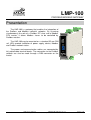
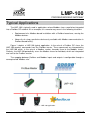
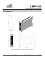
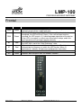
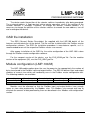
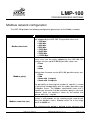
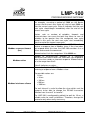
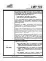
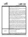
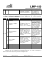
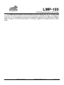
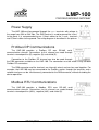
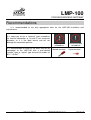
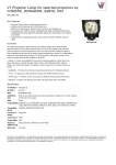
Profibus/Modbus Gateway
LMP-100
User Manual
Profibus/Modbus Gateway
MAN-EN-DE-LMP100-01.00_14
Introduction
Thank you for choosing our Profibus/Modbus Gateway LMP-100. To ensure its proper and
efficient usage, it’s important to read this manual thoroughly to understand how to operate the
LMP-100, before putting it into operation.
About this Manual
1. This manual should be delivered to the end user of the LMP-100.
2. The contents of this manual are subject to change without notice.
3. All rights reserved. No part of this manual may be reproduced in any form without the
written permission from DLG.
4. The specifications contained herein are limited to standard models and do not cover
special products made by order.
5. All precautions were taken on preparing this manual, in order to guarantee the quality of
its information.
CAUTION!
The instrument described in this technical user manual is a device suitable for application
in a specialized technical area. DLG supplied products are submitted to a strict quality control
process. However, industrial control electronic equipment can cause damage to machinery or
processes controlled by them in the event of any failure or improper operations and may even
endanger human lives. The user is responsible for setting and selecting values of the
parameters of the instrument. The manufacturer warns of the risks of incidents with injuries to
both people and goods, resulting from the incorrect use of the instrument.
Contents
PRESENTATION .................................................................................................. 5
HOW TO SPECIFY ............................................................................................... 6
TYPICAL APPLICATIONS ................................................................................... 7
TECHNICAL SPECIFICATIONS ........................................................................... 8
General Characteristics ....................................................................................................... 8
DIMENSIONS ....................................................................................................... 9
FRONTAL ........................................................................................................... 10
CONFIGURATION .............................................................................................. 11
Profibus address configuration .......................................................................................... 11
GSD file installation ........................................................................................................... 12
Module configuration (LMP-100/M) ................................................................................... 12
Modbus network configuration ........................................................................................... 13
Modbus rule configuration ................................................................................................. 16
Diagnostics ........................................................................................................................ 23
Control register .................................................................................................................. 28
ELECTRICAL INSTALLATION .......................................................................... 32
Power Supply .................................................................................................................... 33
Profibus DP Communications ............................................................................................ 33
Modbus RTU Communications .......................................................................................... 33
MECHANICAL INSTALLATION ......................................................................... 34
RECOMMENDATIONS ....................................................................................... 35
WARRANTY ....................................................................................................... 36
LMP-100
PROFIBUS/MODBUS GATEWAY
Presentation
The LMP-100 is a gateway that enables the integration of
the Profibus and Modbus industrial networks. By assuming
simultaneously the role of a Profibus DP slave and a Modbus
RTU master, it allows Modbus slaves to be controlled by
Profibus masters.
The LMP-100 may be mounted on a standard 35 mm DIN
rail. LEDs provide indication of power supply, device, Modbus
and Profibus network states.
The power and communication cables are connected by
fully detachable terminal blocks. The connection to the Profibus
network can also be made through a DB9 connector on the
frontal.
LMP-100 User Manual
MAN-EN-DE-LMP100-01.00_14
All rights reserved to DLG Automação Industrial © 2011 – 2014
Page 5 of 40
LMP-100
PROFIBUS/MODBUS GATEWAY
How to Specify
LMP-100 /
____
Profibus input and output buffers sizing:
/compact: fixed size buffers
/M
modular: buffer sizing
Page 6 of 40
LMP-100 User Manual
MAN-EN-DE-LMP100-01.00_14
All rights reserved to DLG Automação Industrial © 2011 – 2014
LMP-100
PROFIBUS/MODBUS GATEWAY
Typical Applications
The LMP-100 is typically used in applications where Modbus slaves need to be integrated
into a Profibus DP network. As an example, this scenario may occur in the following situations:
•
Replacement of a Modbus-based installation with a Profibus-based one, reusing the
Modbus devices.
•
Necessity of using a particular device only available with Modbus communication in
Profibus-based facility.
Figure 1 depicts a LMP-100 typical application. In the role of a Profibus DP slave, the
LMP-100 receives commands from the Profibus master. These commands are interpreted by
the LMP-100 which, in the role of a Modbus master, forwards them to the Modbus slaves.
Similarly, the LMP-100 periodically scans the Modbus slaves for field data, which are interpreted
and sent to the Profibus master.
The mapping between Profibus and Modbus inputs and outputs is configurable through a
concept called “Modbus rule”.
Figure 1 - LMP-100 application.
LMP-100 User Manual
MAN-EN-DE-LMP100-01.00_14
All rights reserved to DLG Automação Industrial © 2011 – 2014
Page 7 of 40
LMP-100
PROFIBUS/MODBUS GATEWAY
Technical Specifications
General Characteristics
Type
Notes
Communication
Profibus DPV0 and Modbus RTU, both over RS-485
Isolation
Galvanic
Profibus: 9.6k, 19.2k, 45.45k, 93.75k, 187.5k, 500k,1.5M,3M ,6M e 12M
Modbus: 1.2k, 2.4k, 4.8k, 9.6k, 19.2k, 38.4k, 57.6k e 115.2k
-10 ºC a 60 ºC
-40 ºC a 70 ºC
Up to 90%
IP-30 (DIN EN 60529 VDE 0470)
20.4 - 28.8 Vdc
90 mA
ABS plastic and flame resistant polycarbonate
DIN 35 mm rail (DIN EN 60715 TH35)
Cable up to 2.5mm² with “plug-in” type removable connectors
0,2 kg
101 x 22.5 x 119.5 mm. (height x width x depth – without frontal DB9 connector)
Baud rates
Operating temperature
Storage temperature
Relative humidity
IP protection
Input voltage
Current consumption
Construction
Placement
Electrical connection
Aprox. weight
Dimensions
Page 8 of 40
LMP-100 User Manual
MAN-EN-DE-LMP100-01.00_14
All rights reserved to DLG Automação Industrial © 2011 – 2014
LMP-100
PROFIBUS/MODBUS GATEWAY
Dimensions
Figure 2 – Dimensioning for assembling (dimensions in millimeters)
LMP-100 User Manual
MAN-EN-DE-LMP100-01.00_14
All rights reserved to DLG Automação Industrial © 2011 – 2014
Page 9 of 40
LMP-100
PROFIBUS/MODBUS GATEWAY
Frontal
LED
Color
PWR
Green
RUN
Green
BF
Red
ST
Red
TX
RX
Orange
Green
Page 10 of 40
Description
(Power) Indicates power supply operation. Continuously lit LED
indicates proper power supply operation.
(Run) Indicates proper operation of the device. After the device is
energized, the LED will flash 5 times. If the self-test boot routines
succeed, the LED remains lit, indicating proper operation of the device.
If the LED is turned off, a critical error occurred at startup, and in this
case the device will no longer operate correctly.
(Bus Fail) Indicates failure in the Profibus network. When lit means that
the LMP-100 is not in the “Data Exchange” state.
(Status) Indicates presence of failure or diagnostics. The failure is
indicated by the frequency at which the LED flashes. When lit
continuously, indicates the presence of diagnostic information.
Indicates data transmission over the Modbus network.
Indicates data reception over the Modbus network.
LMP-100 User Manual
MAN-EN-DE-LMP100-01.00_14
All rights reserved to DLG Automação Industrial © 2011 – 2014
LMP-100
PROFIBUS/MODBUS GATEWAY
Configuration
The LMP-100 was designed so that its entire configuration is obtained through the
Profibus master. Thus, the configuration process is simplified by eliminating the use of
additional tools. The only parameter that is not configurable through the master is the LMP-100
address on the Profibus network.
It is important to notice that as all configuration is sent to the LMP-100 at the Profibus DP
parameterization state, configuration changes cause the device to leave the data exchange
state and return to the parameterization state, temporarily stopping the data transfer between
the Profibus and Modbus networks.
Note: Whenever functionality of bits grouped into one byte is described, consider bit 0 as
the least significant bit and bit 7 as the most significant bit.
Profibus address configuration
The configuration of the LMP-100 Profibus address is accomplished through the selector
switches located on the side of the device labeled “PROFIBUS ADDRESS”.
There are seven selector switches, which enable the encoding of a binary number
between 0 and 127, representing the device Profibus address. The device must be assigned an
address between 1 and 126, as addresses 0 and 127 are reserved.
The selector switches are numbered from 1 to 7. Switch 1 is the address least significant
bit, and switch 7 is most significant one. As an example, to assign address 23 to the device,
simply convert decimal number 23 into a 7-bit binary number:
2310 = 00101112
As the most significant bit is represented by switch number 7, the selector switches would
have to be configured as:
Switch 1 => ON
Switch 2 => ON
Switch 3 => ON
Switch 4 => OFF
Switch 5 = > ON
Switch 6 => OFF
Switch 7 => OFF
LMP-100 User Manual
MAN-EN-DE-LMP100-01.00_14
All rights reserved to DLG Automação Industrial © 2011 – 2014
Page 11 of 40
LMP-100
PROFIBUS/MODBUS GATEWAY
The device reads the position of the selector switches immediately after being energized.
The assigned address is kept constant during device operation, even if the position of the
selector switches is changed. Therefore, to change the device’s Profibus address it is
necessary to change the position of the selector switches to encode the new address, turn off
and re-energize the device.
GSD file installation
The GSD (General Station Description) file supplied with the LMP-100 details all the
features and characteristics of the device. The file must be installed within the Profibus master
configuration software. The GSD file installation procedure is manufacturer specific, so it is
recommended to consult the respective Profibus master user manual.
After proper installation of the GSD file, the entire configuration of the LMP-100 is done
through the Profibus master configuration software.
For the compact version of the device, use the DLG_0D8A.gsd file. For the modular
version of the equipment (/M), use the DLG_0E6C.gsd file.
Module configuration (LMP-100/M)
The LMP-100 modular option gives the user the power to size appropriately the number of
bytes transferred in the Profibus input and output buffers. The GSD file defines input and output
modules of several sizes which are handled by users in the Profibus master configuration tool.
The following modules are available:
1 word input
1 word output
2 words input
2 words output
4 words input
4 words output
1 word = 2 bytes
8 words input
8 words output
16 words input
16 words output
Modules must be allocated so that the Profibus input and output buffers have enough
space to store data produced by the Modbus rules. The Modbus rule concept and how to
calculate the amount of data produced by them are described in the “Modbus rule configuration”
section.
Page 12 of 40
LMP-100 User Manual
MAN-EN-DE-LMP100-01.00_14
All rights reserved to DLG Automação Industrial © 2011 – 2014
LMP-100
PROFIBUS/MODBUS GATEWAY
Modbus network configuration
The LMP-100 provides the following configuration parameters for the Modbus network:
Parameter
Modbus baud rate
Modbus parity
Description
Modbus network baud rate. All slaves must use the baud
rate adopted by the LMP-100. The possible values are:
• 1200 bps
• 2400 bps
• 4800 bps
• 9600 bps
• 19200 bps
• 38400 bps
• 57600 bps
• 115200 bps
Used as a mechanism to detect data transmission errors. All
slaves must use the parity adopted by the LMP-100. For
firmware versions up to 02.00.00, possible values are:
• Even
• Odd
• None
Starting from firmware version 02.01.00, possible values are:
• Even
• Odd
• None with 1 stop bit
• None with 2 stop bits
The possibility of choosing the number of stop bits is aimed
at increasing interoperability with the widest possible range
of Modbus slaves. The Modbus specification states that 2
stop bits per character shall be used when parity is not used.
However, there are countless slaves on the market that
operate with only 1 stop bit.
Modbus scan time (ms)
Period, in milliseconds, of the scanning cycle used to poll
data from Modbus slaves. Allowed values lie in the range
from 0 to 60000 ms.
The scanning cycle period is defined as the minimum time
LMP-100 User Manual
MAN-EN-DE-LMP100-01.00_14
All rights reserved to DLG Automação Industrial © 2011 – 2014
Page 13 of 40
LMP-100
PROFIBUS/MODBUS GATEWAY
between the start of consecutive Modbus scanning cycles.
For example, assuming a period of 5000 ms the device
ensures that the next scan cycle will start at least 5000 ms
after the current scan cycle. Value 0 indicates that the next
scan cycle should begin immediately after the end of the
current scan cycle.
Modbus response timeout
(ms)
Factors such as number of variables, timeouts and
retransmissions can cause the total time taken to scan all
variables to be greater than the configured scan cycle
period. In this case, the next scan cycle start immediately
after the end of the current scan cycle.
Maximum time in milliseconds that the LMP-100 waits to
receive a response from a Modbus slave. If the slave does
not respond within this time, the LMP-100 considers it as a
failure and resends the command.
Allowed values lie in the range from 10 to 60000 ms.
Number of retransmission attempts of a command.
Retransmissions occur when the slave does not respond or
when the slave sends an incorrect response. Allowed values
lie in the range from 0 to 5.
Modbus retries
Value 0 indicates no retries.
Time waited by the LMP-100 to send a new command after
receiving a response from a Modbus slave.
Modbus interframe silence
The possible values are:
• 0 ms
• 10 ms
• 100 ms
• 500 ms
• 1000 ms
The wait interval is useful to allow the slave which sent the
response to be able to change the RS-485 transceiver
direction from “transmit” to “receive”.
The LMP-100 is configured by default to wait for 10 ms, a
suitable value for most installations. Therefore, change this
parameter only when really necessary.
Table 1 – Modbus network parameterization
Page 14 of 40
LMP-100 User Manual
MAN-EN-DE-LMP100-01.00_14
All rights reserved to DLG Automação Industrial © 2011 – 2014
LMP-100
PROFIBUS/MODBUS GATEWAY
Note: Except for the Modbus parity, all the parameters listed above have a direct influence
on the time interval needed by the LMP-100 to scan all Modbus slaves.
LMP-100 User Manual
MAN-EN-DE-LMP100-01.00_14
All rights reserved to DLG Automação Industrial © 2011 – 2014
Page 15 of 40
LMP-100
PROFIBUS/MODBUS GATEWAY
Modbus rule configuration
The LMP-100 defines a concept named “Modbus rule”. Modbus rules define how to access
Modbus variables that will be transferred to the Profibus network. A rule allows the definition of
which Modbus variables should be mapped.
A rule is classified as input rule or output rule. Input rules allow Modbus variables to be
read and sent to the Profibus master. Output rules allow Modbus variables to be written with
data sent by the Profibus master.
The LMP-100 provides 38 Modbus rules, freely distributed between input and output rules
according to the necessity. Rules are numbered R01, R02, ..., up to R32 (or 38 in the compact
version).
It is essential to understand how Modbus rules are related to the Profibus buffers in order
to operate the device correctly. The LMP-100 has two buffers, named input buffer and output
buffer, each 244 bytes long, used for data exchange with the Profibus master. The input buffer
is where the LMP-100 puts data to be transferred to the Profibus master. This data is polled
from the Modbus slaves. The output buffer is where the LMP-100 places data received from the
Profibus master. This data will be transferred to the Modbus slaves.
In the LMP-100 compact option, input and output buffers have a fixed length of 244 bytes.
In the modular option, the user is allow to size the input and output buffers by inserting modules
in the configuration.
Input rules produce and store data in the input buffer. Assuming an input rule R01, for
example, which specifies reading of 5 Modbus registers, and remembering that a Modbus
register is 2 bytes long it is easy to deduce that the rule produces 10 bytes. Therefore, 10 bytes
from the input buffer stores the value of the 5 Modbus registers read. Still as another example,
rule R12 specifies reading of 7 Modbus digital inputs. As Modbus encodes up to 8 digital inputs
in a byte, this rule will produce 1 byte, also copied to the Profibus input buffer.
Besides computing the total number of bytes produced by an input rule, the only question
remaining is the order in which data is stored in the input buffer. The LMP-100 calculates and
reserves space in the input buffer according to the ascending order of the rules. Therefore,
starting at R01, the LMP-100 checks whether R01 is an input rule. If so, the LMP-100 computes
the number of bytes reserved to map R01, and allocates them in the beginning of the input
buffer. The potential input rules are allocated sequentially in the input buffer. The process is
repeated up to R38.
The procedure is analog for output rules. The computation of the byte total and evaluation
order of the rules are the same.
Page 16 of 40
LMP-100 User Manual
MAN-EN-DE-LMP100-01.00_14
All rights reserved to DLG Automação Industrial © 2011 – 2014
LMP-100
PROFIBUS/MODBUS GATEWAY
A Modbus rule is configured through the following parameters:
Parameter
Description
Modbus function used to read or write Modbus variables.
Determines whether the rule is an input or output rule.
• None: the rule is not executed and does not reserve space
in the Profibus buffers.
• Read Coils: allows reading of one or more digital outputs
(coil). The rule becomes an input rule.
• Read Discrete Inputs: allows reading of one or more digital
inputs. The rule becomes an output rule.
• Read Holding Registers: allows reading of one or more
analog outputs. The rule becomes an output rule.
Modbus function code
• Read Input Registers: allows reading of one or more
analog inputs. The rule becomes an input rule.
• Write Single Coil: allows writing of one digital output. The
rule becomes an output rule.
• Write Single Register: allows writing of one analog output.
The rule becomes an output rule.
• Write Multiple Coils: allows writing of one or more digital
outputs. The rule becomes an output rule.
Modbus slave address
Start address
Number of variables
• Write Multiple Registers: allows writing of one or more
analog outputs. The rule becomes an output rule.
Modbus slave addressed by the rule.
Slaves in the range from 1 to 247 can be addressed.
Together, these two parameters indicate which Modbus variables
are addressed by the rule. The variables of one rule must be
accessed contiguously. For example, one rule is able to read
analog inputs with addresses 1 to 10. If it is necessary to read
analog inputs 1 to 10 and 15 to 20, at least two rules are required.
According to the Modbus specification, each data type (digital
input, digital output, analog input and analog output) can have up
to 65536 variables.
LMP-100 User Manual
MAN-EN-DE-LMP100-01.00_14
All rights reserved to DLG Automação Industrial © 2011 – 2014
Page 17 of 40
LMP-100
PROFIBUS/MODBUS GATEWAY
The “Start Address” parameter determines the start address of the
range of variables. The parameter “Number of variables” indicates
how many variables will be accessed starting from the initial
address.
The “Start address” parameter accepts values in the range from 1
to 65535.
The “Number of variables” in conjunction with the Modbus function
selected in the “Modbus function code” parameter determines the
byte count allocated in the Profibus buffers for the rule. Moreover,
the range of allowed values for the “Number of variables”
parameter depends on the type of variables accessed. The table
below details the mentioned dependencies.
Modbus function
code
Read Coils
Read Discrete Inputs
Write Multiple Coils
Read Holding Registers
Read Input Registers
Write Multiple Registers
Write Single Coil
Write Single Register
Number of variables
(n)
Number of
bytes
reserved
1 ≤ n ≤1952
(n – 1) / 8 + 1
1 ≤ n ≤122
n*2
Parameter is not used
2
Since the maximum value of the “Start address” parameter is
65535, to access variable 65536 a rule with “Start address” less
than or equal to 65535 and “Number of variables” large enough to
address variable 65536 must be created. As examples:
Number of variables
65535
2
65530
7
Addressed variables
65535
65536
65530
65531
65532
65533
65534
65535
65536
Defines whether the input (Input Registers) or output (Holding
Registers) byte order should be inverted.
Byte swap
(available starting at
firmware version
02.01.00)
Page 18 of 40
Start Address
• No: byte order is not inverted.
• Yes: byte order is inverted.
LMP-100 User Manual
MAN-EN-DE-LMP100-01.00_14
All rights reserved to DLG Automação Industrial © 2011 – 2014
LMP-100
PROFIBUS/MODBUS GATEWAY
On variables that require more than 1 byte of storage, the
definition of the byte order is essential for the correct processing
of the variable. There are two possible byte orders considering
that a Modbus analog variable is 2 bytes long:
• Little endian (LE), also known as Intel format.
• Big endian (BE), also known as Motorola format.
The LE order dictates that the variable’s least significant byte
must be stored in the memory address right before the memory
address of the most significant byte. In BE order, the byte
positions are inverted.
Equipments with Modbus communications shall encode their
analog variables in the BE format. Therefore, the analog data
acquired by the LMP-100 is encoded in this format.
Profibus masters and other supervisory systems may be designed
to operate in the LE format. Should that be the case, the LMP-100
may be configured to perform the byte order inversion internally,
thus eliminating the need to program a byte order inversion
algorithm in the PLC, for instance.
When configured to perform the byte order inversion, the LMP100 inverts the input variables before copying them to the
Profibus input buffer, as well as the ouput variables before
sending them to the proper Modbus slave. It is worth noting that
the LMP-100 inverts all variables of a rule configure to acquire
more than one variable.
Defines the behavior of output rules. This parameter is ignored
when the rule is an input rule.
• Every scan cycle: output rules produce an automatic
Modbus write command on each scan cycle. The written
value is the last value received from the Profibus master.
Write trigger
• On value change: output rules produce an automatic
Modbus write command only when the value sent by the
Profibus master is different from the last value written to
Modbus slave.
• User triggered: output rules produce a Modbus write
command only when requested by the control register.
LMP-100 User Manual
MAN-EN-DE-LMP100-01.00_14
All rights reserved to DLG Automação Industrial © 2011 – 2014
Page 19 of 40
LMP-100
PROFIBUS/MODBUS GATEWAY
Choosing between the three available behaviors requires
understanding of the specific application.
The behavior “On value change” is optimal from the Modbus
network standpoint, since data writing occurs only when the
Profibus master sends a different value.
However, this behavior is only totally safe when the variable to be
written is retentive, i.e., it holds the last value even if the Modbus
slave is turned off and on again. This caution is justified by the
following example: an output rule is configured with the behavior
“On value change”. At one point in time, the Profibus master
changes the value of a digital output from 0 to 1. The LMP-100
transfers this change to the appropriate Modbus slave. Sub
sequentially, the Modbus slave is turned off and on again, and the
non-retentive digital output goes back to value 0.
In this situation, the Profibus master keeps sending value 1, but
as the value has not changed, the LMP-100 does not detect
change and does not forward the current value to the Modbus
slave. This situation was caused by the digital output changing
from 1 to 0 when the device was turned off.
The “User triggered” behavior allows the user to control exactly at
which time writing is made. The control register allows the user to
trigger each output rule individually, writing the value available in
the Profibus output buffer. Therefore, output rules with the “User
triggered” behavior need the value to be written copied to the
Profibus output buffer and the trigger fired in the control register.
The writes triggered by the LMP-100 always carry all the variables
addressed by the rule. An output rule addressing, for instance,
five Modbus variables configured with behavior “On value change”
and that at a given time detects the change of only one of the five
variables will result in a Modbus write command containing the
new value of the variable that has changed and the last value of
the other variables.
Sets whether the rule is enabled or disabled. A disabled rule does
not produce activity in the Modbus network.
Enabled
• Yes: the rule is enabled.
• No: the rule is disabled.
In some cases it may be interesting to disable a rule. For
example, a defective Modbus slave can cause considerable
Page 20 of 40
LMP-100 User Manual
MAN-EN-DE-LMP100-01.00_14
All rights reserved to DLG Automação Industrial © 2011 – 2014
LMP-100
PROFIBUS/MODBUS GATEWAY
delays in the LMP-100 scanning cycle, due to communication
timeouts. In this case, it is suggested to disable the rules that
address the faulty slave.
Even not producing activity in the Modbus network, a disabled
rule keeps its space reserved in the Profibus buffers. Thus, the
relative position of data in the buffers for each rule is unchanged,
avoiding reconfigurations in the Profibus master data access.
A rule can also be disabled by changing the parameter “Modbus
function code” to “None”. However, this option is NOT
recommended because it changes the relative position of data in
the Profibus buffers. Thus, the Profibus master will have to be
reconfigured to readjust data access in the buffers.
Table 2 – Modbus rule parameterization
It is important to know how the Modbus functions encode the data exchanged between
masters and slaves, since the LMP-100 transfers to the Profibus buffers Modbus data exactly
as they are exchanged in the Modbus network. Table 3 details how data is encoded according
to each Modbus function.
Modbus function
Read Coils
Read Discrete Inputs
Write Multiple Coils
Encoding
Each variable is encoded as 1 bit. Data is always transferred in
multiples of 1 byte.
The least significant bit of the first byte contains the variable address
by the parameter “Start address”. The following variables will be
encoded toward the most significant bit. When 8 variables fill the
byte, a new byte is allocated, keeping the encoding from the least to
the most significant bit. When there are unused bits in a byte, the bit
is set to 0.
As an example, the digital input variables 5 to 16 are encoded as
shown below.
12
b7
11
b6
10
b5
9
8
b4 b3
byte 1
7
b2
6
b1
5
b0
b7
b6
b5
16
b4 b3
byte 2
15
b2
14
b1
13
b0
The first byte stores the value of variables 5 to 12, and the second
byte stores the value of variables 13 to 16. In the second byte, bits
b4, b5, b6 and b7 are set to 0 because they are unused.
Read Input Registers
Read Holding
Registers
Each variable is encoded as 2 bytes, using “big endian” byte order.
As an example, two analog inputs with addresses 10 and 11 and
values 300 and 10000 are encoded as follows:
LMP-100 User Manual
MAN-EN-DE-LMP100-01.00_14
All rights reserved to DLG Automação Industrial © 2011 – 2014
Page 21 of 40
LMP-100
PROFIBUS/MODBUS GATEWAY
Write Single Register
Write Multiple
Registers
01
MSB
2C
LSB
27
MSB
byte 1
Variable 10
10
LSB
byte 2
Variable 11
MSB is the most significant byte; LSB is the least significant byte.
Variable values are represented in hexadecimal notation:
30010 = 012C16
1000010 = 271016
The value to be written to the digital output is encoded in two bytes.
Write Single Coil
To write 0 to the output, it is necessary to transfer the value 000016.
To write 1 to the output, it is necessary to transfer the value FF0016.
Table 3 – Modbus variables encoding
Page 22 of 40
LMP-100 User Manual
MAN-EN-DE-LMP100-01.00_14
All rights reserved to DLG Automação Industrial © 2011 – 2014
LMP-100
PROFIBUS/MODBUS GATEWAY
Diagnostics
The LMP-100 provides diagnostic information, describing in detail its operation status. The
diagnostic information is encoded in 42 bytes, as shown below.
byte 0
Diagnostic byte count
bytes 1 and 2
Reserved
byte 3
Operation
diagnostics
byte 4
Rule R01 diagnostics
...
...
byte 41
Rule R38 diagnostics
Diagnostic is comprised of several conditions mapped into bits, where bits with value 1
indicate an alarmed condition.
Byte 0 indicates the number of available diagnostic bytes. The LMP-100 provides 42
diagnostic bytes.
Bytes 1 and 2 are reserved.
Byte 3 contains the Modbus rules overall diagnostics, encoded as shown in table 5.
Byte
Bit
0
1
2
3
4
5
Condition
Reserved
Reserved
Reserved
Reserved
Reserved
Exception in Modbus
response
Description
While processing the
Modbus rules, at least one
slave returned a response
with an exception.
3
6
Timeout in Modbus
response
7
Error in Modbus response
While processing the
Modbus rules, at least one
slave did not return a
response within the time
period specified by the
“Modbus response timeout”
parameter.
While processing the
Modbus rules, at least one
slave returned a response
Comments
The LMP-100 remains
in operation. It is
possible to check
which slaves produced
the exception by
checking the rule
specific diagnostics.
The LMP-100 remains
in operation. It is
possible to check
which slaves produced
the exception by
checking the rule
specific diagnostics.
The LMP-100 remains
in operation. It is
possible to check
LMP-100 User Manual
MAN-EN-DE-LMP100-01.00_14
All rights reserved to DLG Automação Industrial © 2011 – 2014
Page 23 of 40
LMP-100
PROFIBUS/MODBUS GATEWAY
with an error. Errors may be
parity errors, incomplete
responses, among others.
which slaves produced
the exception by
checking the rule
specific diagnostics.
Table 4 – Operation diagnostics
Bytes 4 to 41 contain detailed diagnostics of Modbus rules R01 to R38, respectively.
Information is encoded as shown below.
Byte
Bit
Condition
0 Reserved
Description
Exception in Modbus
response
While processing the rule,
the slave returned a
response with an exception.
Timeout in Modbus
response
While processing the rule,
the slave did not return a
response within the time
period specified by the
“Modbus response timeout”
parameter.
3
Error in Modbus
response
While processing the rule,
the slave returned a
response with an error.
Errors may be parity errors,
incomplete responses,
among others.
4
5
6
7
Reserved
Reserved
Reserved
Reserved
1
2
4 – 41
Comments
The LMP-100 remains
in operation. The rule
will be processed in
the next cycle, and the
diagnostic condition
remains active while
the slave responds
with an exception.
The LMP-100 remains
in operation. New
transmission attempts
will be made, and the
diagnostic condition
remains active while
the slave does not
respond.
The LMP-100 remains
in operation. The rule
will be processed in
the next cycle, and the
diagnostic condition
remains active while
the slave responds
with an error.
Table 5 – Modbus rule diagnostics
Diagnostic data can be obtained through two mechanisms. The choice of mechanism is
done via the “Device diagnostics” parameter. The options are:
Page 24 of 40
LMP-100 User Manual
MAN-EN-DE-LMP100-01.00_14
All rights reserved to DLG Automação Industrial © 2011 – 2014
LMP-100
PROFIBUS/MODBUS GATEWAY
Parameter
Profibus input
Profibus extended
diagnostics
No diagnostics
Description
Diagnostic data is transferred to the start of the Profibus
input buffer. Thus, the Profibus master accesses diagnostic
data in the same way that it accesses Modbus input data.
The Modbus input data produced by the Modbus rules are
placed right after the diagnostic data.
Diagnostic data is transferred to the Profibus master via a
Profibus protocol functionality named extended diagnostics.
None of the previous mechanisms is used. Thus, there is no
way the user can get diagnostic data.
(available starting at firmware
version 02.01.00)
The LMP-100 provides exactly the same diagnostic data for both mechanisms.
The choice of mechanism for accessing diagnostic data must take into account certain
factors. The “Profibus input” option lets diagnostic data to be accessed easily, since they are
mapped to the Profibus input buffer. However, as they are mapped to the the input buffer, they
take space in the buffer, reducing the number of Modbus input variables that can be mapped
through the rules. The “Profibus extended diagnostics” option does not make use of the input
buffer to send diagnostic data, taking advantage of the Profibus extended diagnostics
functionality. Thus, the entire input buffer can be used to access Modbus input variables.
However, the Profibus master configuration required to access the extended diagnostic data is
usually more difficult than the configuration to access data from the input buffer. In addition,
some Profibus masters simply do not allow the user to access extended diagnostics.
Looking at the factors mentioned above, the decision on which diagnostics mechanism to
be chosen is weighted by the effort required to access the data, the possibility of reserving part
of the input buffer for diagnostic data, and also by the extended diagnostic data access in the
chosen Profibus master.
The ST (Status) LED is lit when at least one diagnostic condition is alarmed. When all
conditions return to normal, the ST LED turns off. Even if the user chooses not to access
diagnostic data, through the “No diagnostics” option, the ST LED keeps indicating diagnostic
conditions.
In addition to diagnostic conditions, the ST LED is also used to indicate device failure.
Failures cause the device to stop operating. In such cases, the device automatically reboots
every 10 seconds in an attempt to recover. The failure is identified by the frequency with which
the ST LED flashes. While in failure conditions, the ST LED alternates between a minor cycle in
which it blinks rapidly and large cycle when it is turned off. The number of times the LED blinks
in the minor cycle indicates the specific failure. The RUN LED turns off while the device is in
failure conditions. The table below shows the possible failures, how to identify them and the
possible recovery options.
LMP-100 User Manual
MAN-EN-DE-LMP100-01.00_14
All rights reserved to DLG Automação Industrial © 2011 – 2014
Page 25 of 40
LMP-100
PROFIBUS/MODBUS GATEWAY
Page 26 of 40
LMP-100 User Manual
MAN-EN-DE-LMP100-01.00_14
All rights reserved to DLG Automação Industrial © 2011 – 2014
LMP-100
PROFIBUS/MODBUS GATEWAY
Identification by
the ST LED
ST LED blinks
once in the minor
cycle.
Failure
Memory test failure after the
device is energized.
ST LED blinks
twice in the minor
cycle.
Invalid Profibus address.
ST LED blinks
three times in the
minor cycle.
ST LED blinks
four times in the
minor cycle.
Illegal state in the Profibus
state machine.
Modbus communications
layer initialization error.
Insufficient number of bytes in
the input or output buffers to
store all data produced by the
rules.
Recovery
Device goes into a reboot cycle. If the
failure persists, the device has a
hardware defect and must be replaced.
Device goes into a reboot cycle. Set via
the device selector switches a Profibus
address between 1 and 126. Device will
start operating normally after the next
reboot and will be configured with a valid
address.
Device is automatically rebooted, going
into normal operation.
Device is automatically rebooted, going
into normal operation.
Device goes into a reboot cycle until the
configuration is fixed properly.
In the compact option of the LMP-100,
check if the number of bytes produced by
input or output rules does not exceed 244
bytes, considering that 42 input bytes are
ST LED blinks five
allocated if diagnostics is mapped to the
times in the minor
input buffer and that 16 output bytes are
cycle.
allocated for the control register.
In the modular option of the LMP-100,
check if the input and output buffer sizing
is sufficient to store all data produced by
the rules.
Table 6 – Failure identification via the ST LED.
LMP-100 User Manual
MAN-EN-DE-LMP100-01.00_14
All rights reserved to DLG Automação Industrial © 2011 – 2014
Page 27 of 40
LMP-100
PROFIBUS/MODBUS GATEWAY
Control register
The LMP-100 provides the user with a data area called control register, where several
settings can be performed on the device.
The control register is located at the start of the Profibus output buffer, occupying the first
16 bytes. Therefore, to calculate the location of data consumed by the write rules it must be
considered that data is arranged immediately after the control register, after byte 16.
The control register contents are shown below.
byte 0
Slave address
byte 1
Slave activation control
bytes 2 – 6
Write triggers
bytes 7 – 15
Reserved
Bytes 0 and 1 of the control register allow controlling the activation of Modbus slaves.
Activation means the possibility of stopping and reestablishing communications with a Modbus
slave while the LMP-100 is operating, without the need for Modbus rule reconfiguration.
As explained before in the rule configuration section, each rule has a parameter called
“Enabled”, with the purpose of avoiding that a the rule produces activity in the Modbus network.
This parameter is interesting in situations such as failure or removal of a Modbus slave, which
cause network timeouts due to rules that address the referred slave. The “Enabled” parameter
can be set to value “No” in all rules that address the missing or defective Modbus slave,
preventing Modbus communications with the slave. However, it is important to emphasize again
that any change in the LMP-100 parameters stops data exchange while the the device is
reparameterized by the Profibus master.
The activation control in the control register is an option for situations where it is interesting
to the interrupt communications with a Modbus slave without reparameterization of the LMP100. The LMP-100 treats as disabled the Modbus rules that address a deactivated Modbus
slave. The rules remain disabled until slave reactivation is requested in the control register or
until the equipment is reparameterized. When reparameterized the rule enabled state is a
function solely of its “Enabled” parameter value.
Byte 0 must be set with the address of the Modbus slave that will have its activation state
changed. Byte 1 allows choosing if the slave will be activated or deactivated and also trigger the
activation change. The byte encoding is shown below.
Page 28 of 40
LMP-100 User Manual
MAN-EN-DE-LMP100-01.00_14
All rights reserved to DLG Automação Industrial © 2011 – 2014
LMP-100
PROFIBUS/MODBUS GATEWAY
Bit
0
1
2
3
4
5
Function
Reserved
Reserved
Reserved
Reserved
Reserved
Reserved
Description
A rising edge on the bit value triggers the activation state change of the
Modbus slave referred in byte 0, i.e., the bit value must be changed from 0 to
1. Changing it from 1 to 0 does not trigger the activation change.
Defines whether the Modbus slave is activated or deactivated when activation
state change is triggered by bit 6.
6
Trigger
7
Activation
0: deactivates the slave
1: activates the slave
Note: Activation of an active slave or deactivation of an inactive slave has no
effect.
Table 7 – Modbus slave activation control.
The control register is also used to trigger write rules in which the parameter “Write trigger”
is set to “User triggered”. As explained before in the rule configuration section, a user triggered
rule gives the user complete control on when the write command is sent to the Modbus network.
Bytes 2 to 6 of the control register are encoded in a way that each rule has a trigger bit. It is
important to note that the trigger bits only results in Modbus writes if the rule is configured as
user triggered. The other two write options (“Every scan cycle” and “On value change”) are not
affected, since they handle writing in an automatic fashion.
The table below details the byte encoding for write triggering. The write is triggered by a
rising edge in the corresponding bit, i.e., changing its value from 0 to 1. Changing the bit value
from 1 to 0 does not trigger writing.
Byte
2
3
Bit
0
1
2
3
4
5
6
7
0
1
2
Description
Rule R08 user trigger
Rule R07 user trigger
Rule R06 user trigger
Rule R05 user trigger
Rule R04 user trigger
Rule R03 user trigger
Rule R02 user trigger
Rule R01 user trigger
Rule R16 user trigger
Rule R15 user trigger
Rule R14 user trigger
LMP-100 User Manual
MAN-EN-DE-LMP100-01.00_14
All rights reserved to DLG Automação Industrial © 2011 – 2014
Page 29 of 40
LMP-100
PROFIBUS/MODBUS GATEWAY
3
4
5
6
7
0
1
2
3
4
5
6
7
0
1
2
3
4
5
6
7
0
1
2
3
4
5
6
7
4
5
6
Rule R13 user trigger
Rule R12 user trigger
Rule R11 user trigger
Rule R10 user trigger
Rule R09 user trigger
Rule R24 user trigger
Rule R23 user trigger
Rule R22 user trigger
Rule R21 user trigger
Rule R20 user trigger
Rule R19 user trigger
Rule R18 user trigger
Rule R17 user trigger
Rule R32 user trigger
Rule R31 user trigger
Rule R30 user trigger
Rule R29 user trigger
Rule R28 user trigger
Rule R27 user trigger
Rule R26 user trigger
Rule R25 user trigger
Reserved
Reserved
Rule R38 user trigger
Rule R37 user trigger
Rule R36 user trigger
Rule R35 user trigger
Rule R34 user trigger
Rule R33 user trigger
Table 8 – User trigger control.
Note: bytes 7 to 15 of the control register are reserved and have no effect on the device
operation.
If the user has no interest in using the functionality provided by the control register, it can
be disabled via the “Control register” parameter.
Parameter
Control register
Description
Disables the control register functionality and do not reserve
memory for it at the Profibus output buffer.
(available starting at firmware
version 02.01.00)
Page 30 of 40
LMP-100 User Manual
MAN-EN-DE-LMP100-01.00_14
All rights reserved to DLG Automação Industrial © 2011 – 2014
LMP-100
PROFIBUS/MODBUS GATEWAY
It is important to be aware that by disabling the control register the user is no longer able
to control the runtime activation of slaves and it becomes impossible to trigger user-triggered
write rules. It is also important to note that the output buffer becomes fully available for Profibus
output variables, since the control register is no longer mapped at the beginning of the output
buffer.
LMP-100 User Manual
MAN-EN-DE-LMP100-01.00_14
All rights reserved to DLG Automação Industrial © 2011 – 2014
Page 31 of 40
LMP-100
PROFIBUS/MODBUS GATEWAY
Electrical Installation
Figure 3 – LMP-100 electrical connections.
Attention: all cables must be “crimped” with eyelet terminals for cables up to 1.5 mm²
unless otherwise stated. For the interconnection of communication signals it is recommended to
use woven shielded cables and the woven grounding must be done on the S terminal and other
ground references located at the bus extremities.
Page 32 of 40
LMP-100 User Manual
MAN-EN-DE-LMP100-01.00_14
All rights reserved to DLG Automação Industrial © 2011 – 2014
LMP-100
PROFIBUS/MODBUS GATEWAY
Power Supply
The LMP-100 must be powered through the + e – terminals with voltage in
the range from 20.4 to 28.8 Vdc. The GND terminal is used to ground the “mass”
to the panel. It is recommended to use 1,5mm² cables to the + and – terminals
and 2,5mm² cables to the ground. The wiring diagram is described in the picture.
Profibus DP Communications
The LMP-100 provides a Profibus DP over RS-485 serial
communication channel. Connections to this channel are made through
terminals named positive (B), negative (A) and shield (S).
Connection to the Profibus DP channel can also be made through
the DB9 connector available on the LMP-100. The connection must be made using standard
Profibus DP connectors.
The DB9 connector and the terminals are internally wired, and can be used together. For
example, the LMP-100 may be connected to the Profibus master through the terminals and a
network analyzer can be simultaneously connected to the DB9 connector, without disturbing the
device operation.
Modbus RTU Communications
The LMP-100 provides a Modbus RTU over RS-485 serial
communication channel. Connections to this channel are made through
terminals named positive (485+), negative (485-) and shield (S).
LMP-100 User Manual
MAN-EN-DE-LMP100-01.00_14
All rights reserved to DLG Automação Industrial © 2011 – 2014
Page 33 of 40
LMP-100
PROFIBUS/MODBUS GATEWAY
Mechanical Installation
Fix the LMP-100 on the the top of the DIN rail.
Using a screwdriver, pull the lock that is
located at the bottom of the LMP-100. After
pulling the lock, fix the LMP-100 at the bottom
of the DIN rail.
Release the lock and make sure that the LMP100 is attached to the DIN rail.
Page 34 of 40
LMP-100 User Manual
MAN-EN-DE-LMP100-01.00_14
All rights reserved to DLG Automação Industrial © 2011 – 2014
LMP-100
PROFIBUS/MODBUS GATEWAY
Recommendations
It is recommended to use only appropriate tools for the LMP-100 installation and
maintenance.
It is necessary to use a “terminal” type screwdriver
for terminal connection or 1/8 with 3 mm maximum
diameter, as it is the ideal format and will not
damage the connector aperture.
It is recommended to crimp all the wires that will be
connected to the LMP-100 with a pre-isolated
“needle” type or “eyelet” type terminal for cables of
0,5 ~ 1,5 mm2.
Inappropriate
screwdriver
Needle terminal
LMP-100 User Manual
MAN-EN-DE-LMP100-01.00_14
All rights reserved to DLG Automação Industrial © 2011 – 2014
Recommended
screwdriver
Eyelet terminal
Page 35 of 40
LMP-100
PROFIBUS/MODBUS GATEWAY
Warranty
The manufacturer assures to the equipment owners, identified by the purchase invoice,
warranty of 1 (one) year as follows:
1. The warranty period begins on the data of the invoice issue.
2. Within the warranty period, the labor and parts used for repairing damage occurred in
normal use are free.
3. For repairs, send the equipment along with the shipping invoices to our factory in
Sertaozinho, Sao Paulo state, Brazil. DLG’s address is available at the end of this
manual.
4. The owner is responsible for transportation costs and risks.
5. Warranty will be automatically suspended if changed are made to the equipment by
personnel not authorized by DLG, defects caused by mechanical shock, exposure to
conditions unfit for use or tampering with the product.
6. DLG disclaims any charge relating to unauthorized repairs or replacements due to
failures caused by agents external to the equipment, the improper use of them and as a
result of unforeseeable circumstances or major forces.
7. DLG ensures full operation of the equipment described herein and all existing
operations.
Page 36 of 40
LMP-100 User Manual
MAN-EN-DE-LMP100-01.00_14
All rights reserved to DLG Automação Industrial © 2011 – 2014
Notes
DLG Automação Industrial Ltda.
Rua José Batista Soares, 53
Distrito Industrial – 14176-119
Sertãozinho – São Paulo – Brasil
Fone: +55 (16) 3513-7400
www.dlg.com.br
MAN-EN-DE-LMP10001.00_14
GATEWAY PROFIBUS / MODBUS
LMP-100
DLG reserves the right to change this manual contents without
notice in order to keep it updated with future product improvements.