1
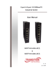
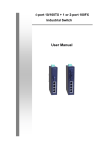
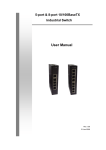
Universal Remote Profibus
XM-210 DP
User Manual
Universal Remote Profibus
MAN-EN-DE-XM210DP-01.00_14
Introduction
Thank you for choosing our Universal Remote Profibus XM-210 DP. To ensure its proper
and efficient usage, it’s important to read this manual thoroughly to understand how to operate
the XM-210 DP, before putting it into operation.
About this Manual
1.
This manual should be delivered to the end user of the XM-210 DP;
2.
The contents of this manual are subject to change without notice;
3.
All rights reserved. No part of this manual may be reproduced in any form without the
written permission from DLG;
4.
The specifications contained herein are limited to standard models and do not cover
special products made by order;
5.
All precautions has been taken for preparation of this manual, in order to guarantee the
quality of information.
CAUTION!
The instrument described in this technical user manual is a device suitable for application
in a specialized technical area. DLG supplied products are submitted to a strict quality control
process. However, industrial control electronic equipment can cause damage to machinery or
processes controlled by them in the event of any failure or improper operations and may even
endanger human lives. The user is responsible for setting and selecting values of the
parameters of the instrument. The manufacturer warns of the risks of incidents with injuries to
both people and goods, resulting from the incorrect use of the instrument.
Contents
PRESENTATION .................................................................................................. 6
TYPICAL APPLICATIONS ................................................................................... 7
TECHNICAL SPECIFICATIONS ........................................................................... 8
Input Characteristics ............................................................................................................ 8
General Characteristics and Precision ................................................................................ 9
HOW TO SPECIFY ............................................................................................... 9
DIMENSIONS ..................................................................................................... 10
MECHANICAL INSTALLATION ......................................................................... 11
ELECTRICAL INSTALLATION .......................................................................... 12
Power Supply .................................................................................................................... 13
Digital Inputs ...................................................................................................................... 13
Relay Outputs and Alarms ................................................................................................. 14
Coding bits for alarms ........................................................................................................ 15
Thermocouple inputs ......................................................................................................... 16
Current inputs .................................................................................................................... 17
Voltage inputs .................................................................................................................... 17
Logic level inputs ............................................................................................................... 18
OPERATING ....................................................................................................... 21
Starting the XM-210 DP ..................................................................................................... 21
Indication ........................................................................................................................... 23
Test button......................................................................................................................... 23
RECOMMENDATIONS ....................................................................................... 24
WARRANTY ....................................................................................................... 25
XM-210 DP
UNIVERSAL REMOTE PROFIBUS
Presentation
The Universal Remote Profibus XM-210 DP is
designed to promote versatility and robustness in industrial
plants.
With its processing core based in the ARM®
technology, the XM-210 DP offers speed and accessibility
to field variables through the Profibus DP protocol over the
RS-485 physical interface, thus enabling the acquisition of
16 inputs from several kind of signals such as
thermocouples, RTD resistive sensors, current, tension,
frequency and logical levels.
Picture 1
The available inputs and product features are described below:
Page 6 of 28
•
Thermocouples type J, K, T, R, S, E, N, B (ITS-90) with cold junction
compensation
•
RTD type PT-100 (two or three wires)
•
Current 0-20 mA e 4-20 mA
•
Tension 0-75 mV, 0-5 V e 0-10 V
•
Logical level maximum amplitude 10 Vdc
•
Frequency up to 10KHz with 4 simultaneous channels with 0,3 V to 50 V
sensibility
•
2 digital inputs isolated up 30 V for of alarms and status recognition
•
2 alarm levels per channel, configurable (high, low, differential) with hysteresis and
delay of 1 to 10 seconds
•
2 relay outputs for alarm status
•
Fully detachable (plug-in type) connection to the terminal block
XM-210 DP User Manual
MAN-EN-DE-XM210DP-01.00_14
All rights reserved to DLG Automação Industrial
XM-210 DP
Universal Remote Profibus
Typical Applications
The Universal Remote Profibus XM-210 DP in designed to several types of industrial
applications, easing the concentration of distributed field data. The XM-210 DP applications
demonstrate high optimization in remote field data acquisition, which were previously delegated
to controllers, increasing the process scalability and decreasing costs.
All the 16 inputs of the XM-210 DP acquire field data reliably for the supervision and
control systems, so the universal remotes can be highly used to collect information from any
point of the plant floor.
Picture 2 – Profibus network topology with the XM-210 DP
XM-210 DP User Manual
MAN-EN-DE-XM210DP-01.00_14
All rights reserved to DLG Automação Industrial
Page 7 of 28
XM-210 DP
UNIVERSAL REMOTE PROFIBUS
Technical Specifications
Input Characteristics
Type
Input Signal
Input Impedance
Parameter
Current
Voltage
Logic Level
Thermocouple
Cold
Junction
Comp.
PT-100
Frequency
Current
Voltage
Thermocouple
PT-100
Frequency
Current
Voltage
A/D Precision (FS)
Linearization
Frequency Precision
Digital Inputs
Page 8 of 28
Thermocouple
PT-100
Cold
Junction
Comp.
Thermocouple
PT-100
0.02 @10000Hz
Current
Voltage
Frequency
Min.
Max.
Comments
0
0
0
-270
20
10
10
1820
Iin < 22mA
-10
+60
Operation range
Vin < 10,5V
Unit
mA
Fin < 2Hz
Vdc
B, E J, K, N, R, S, T
-200
850
Two or Three wires
0.0004 10
0.3 to 50 Vdc sensibility
49
5
5
5
150
@10Vp 10KHz
0-20
±1
4-20
±1
0-75
± 0.003
0-5
± 0.25
0-10
± 0.5
± 0,1
Pt
± 0.1
ºC
kHz
Ω
MΩ
KΩ
uA
mV
%
± 1.5
ºC
0.1
0.2
ºC
0.4
0
0.1
4
26
20
XM-210 DP User Manual
MAN-EN-DE-XM210DP-01.00_14
All rights reserved to DLG Automação Industrial
%
mA
Vdc
Hz
XM-210 DP
Universal Remote Profibus
General Characteristics and Precision
Type
Alarms
Communication
Operating temperature
Thermal stability
Relative humidity
IP protection
Input voltage
Power consumption
Construction
Placement
Electrical connection
Aprox. Weight
Dimensions
Comments
Two relay outputs: RL1 e RL2 SPDT max. 3 A / 220 Vac
2 RS-485 ports, isolated and with transient protection filter
Baud rates (bps): 9.6k, 19.2k, 45.45k, 93.75k, 187.5k, 500k, 1.500M, 3M, 6M and
12M
Profibus DPV0 protocol
–10 ºC to 60 ºC
±0.005% / °C span @ 25°C
Up to 90%
IP-50 (DIN EN 60529 VDE 0470)
85 ~ 260 Vac, 50 - 60Hz (XM-210DP AC) or 18 ~ 30 Vdc (XM-210DP DC)
10 VA
Aluminum and side panels in PA 6.6-FR (flame resistant polyamide)
DIN35 rail (DIN EN 60715 TH35)
Cable up to 2.5mm² with “plug-in” type removable connectors
0.5 kg
59 x 208 x 75 mm. (height x width x depth)
How to Specify
XM-_10DP
____
__
Enclosure
2 Standalone universal converter (XM-210DP)
6 Universal converter installed inside IP-65 box (XM-610DP)
Input Voltage
AC 85 ~ 260 Vac
DC 18 ~ 30 Vdc
Housing Material
M Indicates metallic IP-65 box (XM-610DP)
XM-210 DP User Manual
MAN-EN-DE-XM210DP-01.00_14
All rights reserved to DLG Automação Industrial
Page 9 of 28
XM-210 DP
UNIVERSAL REMOTE PROFIBUS
Dimensions
Picture 3 – Dimensioning for assembling (dimensions in millimeters)
Page 10 of 28
XM-210 DP User Manual
MAN-EN-DE-XM210DP-01.00_14
All rights reserved to DLG Automação Industrial
XM-210 DP
Universal Remote Profibus
Mechanical Installation
To correctly install the Universal Remote Profibus XM-210 DP an appropriate screwdriver
shall be used so the mechanical parts are not damaged. A “terminal” type 1/8” screwdriver is
recommended. The following steps details the installation.
1. Place the bottom of the XM-210 DP in the DIN 35 mm
rail as shown in Figure 4.
Figure 4
2. Press the top part of the XM-210 DP until hearing a
click. To remove the XM-210 DP, just apply opposite force,
i.e., force the XM-210 DP up and pull it out.
Figure 5
3. The XM-210 DP is designed to be installed in regular DIN 35 mm trails and after the
installation the equipment must remain securely fastened and must not present any slack within
the trail. If there is any slack, the trail is possibly not standard.
XM-210 DP User Manual
MAN-EN-DE-XM210DP-01.00_14
All rights reserved to DLG Automação Industrial
Page 11 of 28
XM-210 DP
UNIVERSAL REMOTE PROFIBUS
Electrical Installation
Picture 6 – Top Terminal
Picture 7 – Bottom Terminal
Page 12 of 28
XM-210 DP User Manual
MAN-EN-DE-XM210DP-01.00_14
All rights reserved to DLG Automação Industrial
XM-210 DP
Universal Remote Profibus
Attention: All cables must be “crimped” with eyelet type terminals for cables up to 1.5 mm
unless otherwise stated. The XM-210 DP input type selection is done entirely through the GSD
file and there are no configuration jumpers. It is recommended to use woven shielded cables
and the woven grounding should be mostly done around the field instruments at just one point.
Power Supply
The XM-210 DP must be powered through terminals 1 and 2 with
full-range voltage ranging from 90 to 260 Vac. Terminal 3 is used to
ground the "mass" to the panel and it is recommended to use 1.5 mm²
cables for the phases and 2.5 mm² for grounding. The electric scheme is
described in the picture.
Digital Inputs
The digital inputs are used for alarm status and recognition. The
inputs I1 and I2 are photo coupled, with sensibility from 10 to 30 Vdc,
common for the two inputs, NPN driven. Digital input I1 is used to reset or
recognize RL1 and RL2 alarm conditions and digital input I2 is used like a
status flag for general use. The electric scheme is described in the picture
where terminals 7 and 8 are the NPN inputs and terminal 9 the positive
source common.
The digital inputs can be read through slot 17 – Digital Inputs.
Bit 0 – Input 1
Bit 1 – Input 2
Slot 15 – Digital Inputs
Bit
Function
0 Digital input 1
1 Digital input 2
2 Error reading calibration memory (0: ok, 1 = error)
XM-210 DP User Manual
MAN-EN-DE-XM210DP-01.00_14
All rights reserved to DLG Automação Industrial
Page 13 of 28
XM-210 DP
UNIVERSAL REMOTE PROFIBUS
Relay Outputs and Alarms
The relay digital outputs can be used for general purpose, and can
be configured through the output byte in slot 20 (Relay 1 and 2). The
outputs can only be reseted through the slot in the table below this topic.
The electric scheme is described in the picture for the SPDT relay
type, with the common contact connected to terminals 5 and 38, the NO
contacts to terminals 6 and 39 and the NC contacts to terminals 4 and
37.
Value
1
2
3
4
Slot 20 – Relay 1 and 2
Index
Action
xxxx xxx1
Deactivate relay 1
xxxx xx1x
Deactivate relay 2
xxxx x1xx
Activate relay 1
xxxx 1xxx
Activate relay 2
Bit 0 – Reset output 1
Bit 2 – Set output 1
Bit 1 – Reset output 2
Bit 3 – Set output 2
The XM-210 DP has two independent alarms for each input channel totalizing 32 alarms.
Each alarm can be configured with up to 4 types of conditions: inoperative, low value, high
value and differential.
Inoperative: No alarm.
Low value: The alarm is active as soon as the input value
is lower than the set point.
High value: The alarm is active as soon as the input
value is higher than the set point.
Differential: The differential mode is defined by the set
point and the hysteresis. The set point defines the center
reference point and the hysteresis increases the reference
range. If the input signal lies inside the reference range that alarm is not
Figure 8
active. Otherwise, if the input signal lies outside the reference range, the
alarm becomes active. For example, to define a reference ranging from 400 to 600, define the
set point as 500 and the hysteresis as 100. When the input signal is lower than 400 or higher
than 600 the alarm is active.
Page 14 of 28
XM-210 DP User Manual
MAN-EN-DE-XM210DP-01.00_14
All rights reserved to DLG Automação Industrial
XM-210 DP
Universal Remote Profibus
The hysteresis is the term relative to the delay between the activation or deactivation of a
condition. In the XM-210 DP the operation mode can change according to the selected alarm
condition.
For example:
With low value selected, the activation only happens after the input value is lower than the
set point and deactivated when the input value is higher than the set point plus the hysteresis.
With high value selected, the activation only happens after the input value is higher than
the set point and deactivated when the input value is lower than the set point less the
hysteresis.
The waiting time defines how many seconds the output waits to be activated.
The set-point defines the alarm trigger.
Observations:
For greater security using relays in burn-out conditions, or when there is disruption of the
PT-100 cable (see PT-100 input) it is recommended to configure the relay triggering wait time to
more than 5 seconds. This condition is important to avoid operational failures, for example,
turbine “trips” or any other system that relies on free error states, recalling that burn-uut is an
error condition of the process.
Coding bits for alarms
The table below indicates each bit between channels and alarms (4 bytes).
Dec
1
2
3
4
5
6
7
8
Dec
1
2
3
4
5
6
7
8
Slot 18 – Alarm 1
Byte 0
Action
xxxx xxx1
Alarm 1 channel 1
xxxx xx1x
Alarm 1 channel 2
xxxx x1xx
Alarm 1 channel 3
xxxx 1xxx
Alarm 1 channel 4
xxx1 xxxx
Alarm 1 channel 5
xx1x xxxx
Alarm 1 channel 6
x1xx xxxx
Alarm 1 channel 7
1xxx xxxx
Alarm 1 channel 8
Slot 18 – Alarm 2
Byte 2
Action
xxxx xxx1
Alarm 2 channel 1
xxxx xx1x
Alarm 2 channel 2
xxxx x1xx
Alarm 2 channel 3
xxxx 1xxx
Alarm 2 channel 4
xxx1 xxxx
Alarm 2 channel 5
xx1x xxxx
Alarm 2 channel 6
x1xx xxxx
Alarm 2 channel 7
1xxx xxxx
Alarm 2 channel 8
Dec
1
2
3
4
5
6
7
8
Slot 18 – Alarm 1
Byte 1
Action
xxxx xxx1
Alarm 1 channel 9
xxxx xx1x
Alarm 1 channel 10
xxxx x1xx
Alarm 1 channel 11
xxxx 1xxx
Alarm 1 channel 12
xxx1 xxxx
Alarm 1 channel 13
xx1x xxxx
Alarm 1 channel 14
x1xx xxxx
Alarm 1 channel 15
1xxx xxxx
Alarm 1 channel 16
Dec
1
2
3
4
5
6
7
8
Slot 18 – Alarm 2
Byte 3
Action
xxxx xxx1
Alarm 2 channel 9
xxxx xx1x
Alarm 2 channel 10
xxxx x1xx
Alarm 2 channel 11
xxxx 1xxx
Alarm 2 channel 12
xxx1 xxxx
Alarm 2 channel 13
xx1x xxxx
Alarm 2 channel 14
x1xx xxxx
Alarm 2 channel 15
1xxx xxxx
Alarm 2 channel 16
Obs: Para utilizar valores negativos em configurações como set point ou histerese, use:
65536 – valor_negativo. Por exemplo, para set point a -100 °C, use: 65536 – 100 = 65436.
XM-210 DP User Manual
MAN-EN-DE-XM210DP-01.00_14
All rights reserved to DLG Automação Industrial
Page 15 of 28
XM-210 DP
UNIVERSAL REMOTE PROFIBUS
PT-100 Input
The PT-100 inputs type are linearized according to ITS-90. With a
current source circuit and cable compensation the XM-210 DP eliminates
the line charging effect, and with resistive sensors measurement it stands
as a precise temperature measurement system. The sensor
measurement terminals are positive (V) and negative (G) from channels
CH1 up to CH16 and the cable compensation measurement is done in the
(I) terminals referenced to the negative (G).
If the PT-100 cables are not connected or are open, a burn-out
signal will be represented by an indication of -200°C in the respective
channel.
The XM-210 DP detects the missing sensor and disables the alarm states associated to
the open channel.
The PT-100 inputs can be read through slots 1 to 16 if they are configured as PT-100
through the channel sensor type parameter.
The scale of the signal is given by: T*10, ie to 100°C the value of channel is 1000.
Thermocouple inputs
The thermocouple inputs are linearized as according to ITS-90.
With a cold junction compensation circuit, the XM-210 DP eliminates the
Seebeck effect in the cable connections, standing as a precise system
for high temperature or high differentials measurements. The sensor
measurement terminals are positive (V) and negative (G) from channels
CH1 up to CH16. Terminal (I) is not used in this configuration. Terminal
line (I) is not used in this configurations.
The thermocouple inputs can be read through slots 1 to 16 if they
are configured as thermocouple through the channel sensor type
parameter with the available thermocouple types.
The scale of the signal is given by: T*10, ie to 100°C the value of
channel is 1000.
Page 16 of 28
XM-210 DP User Manual
MAN-EN-DE-XM210DP-01.00_14
All rights reserved to DLG Automação Industrial
XM-210 DP
Universal Remote Profibus
Current inputs
The XM-210 DP has two current input configurations: 0-20 mA and 4-20 mA. The scheme
for both configurations is described in the picture, where the current loop positive is connected
to the line terminals (I) and the negative to terminals (G) from channels CH1 up to CH16. The
positive terminals (V) are not used in this configuration.
The current inputs can be read through slots 1 to 16 if they are configured as current
inputs through the channel sensor type parameter.
The scale of the signal is given by: mA*1000, ie to 20mA the value of channel is 20000.
3 Wire Connection
2 Wire Connection
Voltage inputs
The XM-210 DP has three voltage input configurations: 0-75 mV,
0-5 V and 0-10 V. The scheme for the configurations is described in the
picture, where the positive is connected to the terminals (V) and the
negative to terminals (G) from channels CH1 up to CH16. The line
terminals (I) are not used in this configuration.
The current inputs can be read through slots 1 to 16 if they are
configured as voltage inputs through the channel sensor type
parameter.
The scale of the signal is given by: V*1000, ie to 10V the value of
channel is 10000.
Note: The maximum allowed voltage for correct operation of the XM-210 DP is 10.5
V.
XM-210 DP User Manual
MAN-EN-DE-XM210DP-01.00_14
All rights reserved to DLG Automação Industrial
Page 17 of 28
XM-210 DP
UNIVERSAL REMOTE PROFIBUS
Logic level inputs
The XM-210 DP has logic level inputs with 0 to 10 Vdc sensibility.
The 0 to 3 V range corresponds to logic level 0 while the 5 to 10 V
range corresponds to logic level 1. The scheme is described in the
picture, where the positive is connected to the terminals (V) and the
negative to terminals (G) from channels CH1 up to CH16. The line
terminals (I) are not used in this configuration.
The logic level inputs can be read through slots 1 to 16 if they are
configured as logic level inputs through the channel sensor type
parameter.
The scale of the signal is given by: LL*1, ie to “1” the value of
channel is “1”.
Note: The maximum allowed voltage for correct operation of the XM-210 DP is 10.5
V.
Page 18 of 28
XM-210 DP User Manual
MAN-EN-DE-XM210DP-01.00_14
All rights reserved to DLG Automação Industrial
XM-210 DP
Universal Remote Profibus
Frequency inputs
The XM-210 DP has frequency inputs with 0.3 to 50 Vdc sensibility
and 0.3 Hz to 10 KHz reading. The scheme is described in the picture,
where the positive is connected to the terminals (V) and the negative to
terminals (G) from channels CH1 up to CH4. The line terminals (I) are
not used in this configuration.
The frequency inputs can be read through slots 1 to 16 if they are
configured as frequency inputs through the channel sensor type
parameter.
The scale of the signal is given by: Hz*1, ie to 10Hz the value of
channel is 10.
Profibus DP Communication
The XM-210 DP has one serial communications channels using
the Profibus DP protocol over the RS-485 media. The indication is
done by the BF (Bus Fail, red) led.
The picture describes the connection scheme of the
communication channel. The positive is connected to terminal 69 and
the negative to terminal 68.
Terminal 67 must be used for the communications cable woven.
Note: in some devices the labels A (green) and B (red) can be used
for Profibus communications. In this case it must be connected to the
negative and positive terminals, respectively.
XM-210 DP User Manual
MAN-EN-DE-XM210DP-01.00_14
All rights reserved to DLG Automação Industrial
Page 19 of 28
XM-210 DP
UNIVERSAL REMOTE PROFIBUS
When using DB9 connectors commonly used with the Profibus DP protocol the frontal
female DB9 connector of the XM-210 DP must be used.
The address assignment to the XM-210 DP in the Profibus network is done using the keys
available at the frontal. The address is entered as a binary base number ranging from 1 to 125,
for instance:
1.(20) + 0.(21) + 1.(22) + 0.(23) + 0.(24) + 0.(25) + 0.(26) = 5
NOTE: If the address is higher than 125 the XM-210 DP will indicate failure through the RUN
led that will blink continuously with a 2 Hz frequency.
Page 20 of 28
XM-210 DP User Manual
MAN-EN-DE-XM210DP-01.00_14
All rights reserved to DLG Automação Industrial
XM-210 DP
Universal Remote Profibus
Operating
Starting the XM-210 DP
The
Universal
Remote
Profibus XM-210 DP is designed
to ally the advantages in the
distribution and collection of the
field variables with the Profibus
protocol compatibility, being able
to make them available along
with its settings to controllers and
supervision systems.
Through the GSD file and
software as Simatic Manager ©
or Sycon©, it’s possible to
configure all the parameters in a
structured way.
Some items from the XM210 DP parameterization follow:
Configuration:
• Sensor type
selection.
• Offset setting for
each selected sensor.
• Alarm type selection: low, high or differential.
• Alarm hysteresis setting.
• Alarm set point setting.
• Waiting time for alarm activation.
Output Alarms:
• Table for selecting outputs for the input channels.
• All input channels can be configured to activate the outputs.
• Each input channel can create a combination of outputs activation.
• Outputs 1 and 2 reset.
Led indications:
• Operation and communications indication through leds in the equipment.
XM-210 DP User Manual
MAN-EN-DE-XM210DP-01.00_14
All rights reserved to DLG Automação Industrial
Page 21 of 28
XM-210 DP
UNIVERSAL REMOTE PROFIBUS
For some configurators, it is important to note that the modules available in the XM210-DP
must be manually inserted and in the order they are displayed, for example: Channel 1, 2, 3 ..
16; digital inputs; room temp.; Alarms 1 and 2; Relay 1 and 2.
For proper operation, all modules must be inserted according to the window below:
If the module sequence is not in the correct order, it will cause problems in the equipment.
When more than one slave in the bus is used, just select the slave and copy to the other
addresses in the network, so all the modules and parameters of the slave also get copied. The
address must be modified to be next address available in the PLC memory table.
Page 22 of 28
XM-210 DP User Manual
MAN-EN-DE-XM210DP-01.00_14
All rights reserved to DLG Automação Industrial
XM-210 DP
Universal Remote Profibus
Indication
The XM-210 DP has state indication leds:
•
Power: indicates that the XM-210 DP is
energized.
RUN: on startup it blinks 5 times per second
and after 5 seconds stay turned on. If it keeps
blinking after 5 seconds it is indicating failure.
•
•
RL1 and RL2: The states of relays 1 and 2.
BF: If Bus Fail is active it indicates that the
XM-210 DP is not performing Data Exchange.
•
Test button
The test button located next to the terminals (see Picture)
can be used for any purpose, making available a status bit that
can be read through Slot 17 Digital Inputs.
Bit 3 – key
XM-210 DP User Manual
MAN-EN-DE-XM210DP-01.00_14
All rights reserved to DLG Automação Industrial
Page 23 of 28
XM-210 DP
UNIVERSAL REMOTE PROFIBUS
Recommendations
It’s recommended to use only appropriate tools for the XM-210 DP installation and
maintenance.
It is necessary to use a “terminal” type screwdriver
for terminal connection or 1/8 with 3mm maximum
diameter, as it is the ideal format and will not
damage the connection aperture.
It is recommended to crimp all the wires that will be
connected to the XM-210 DP with a pre-isolated
“needle” type or “eyelet” type terminal for cables of
0.5 - 1.5mm2.
Page 24 of 28
Inappropriate
screwdriver
Needle Terminal
XM-210 DP User Manual
MAN-EN-DE-XM210DP-01.00_14
All rights reserved to DLG Automação Industrial
Recommended
screwdriver
Eyelet Terminal
XM-210 DP
Universal Remote Profibus
Warranty
The manufacturer assures to the equipment owners, identified by the purchase invoice,
warranty of 1 (one) year as follows:
1 - The warranty period begins on the data of the invoice issue;
2 - Within the warranty period, the labor and parts used for repairing damage occurred in
normal use are free;
3 - For repairs, send the equipment along with the shipping invoices to our factory in
Sertãozinho, São Paulo state, Brazil. DLG’s address is available at the end of this
manual;
4 - The owner is responsible for transportation costs and risks;
5 - Warranty will be automatically suspended if changed are made to the equipment by
personnel not authorized by DLG, defects caused by mechanical shock, exposure to
conditions unfit for use or tampering with the product;
6 - DLG disclaims any charge relating to unauthorized repairs or replacements due to
failures caused by agents external to the equipment, the improper use of them and as a
result of unforeseeable circumstances or major forces;
7 - DLG ensures full operation of the equipment described herein and all existing operations.
XM-210 DP User Manual
MAN-EN-DE-XM210DP-01.00_14
All rights reserved to DLG Automação Industrial
Page 25 of 28
XM-210 DP
UNIVERSAL REMOTE PROFIBUS
Notes
Page 26 of 28
XM-210 DP User Manual
MAN-EN-DE-XM210DP-01.00_14
All rights reserved to DLG Automação Industrial
DLG Automação Industrial Ltda.
Rua José Batista Soares, 53
Distrito Industrial – 14176-119
Sertãozinho – São Paulo – Brasil
Fone: +55 (16) 3513-7400
www.dlg.com.br
MAN-EN-DE-XM210DP01.00_14
UNIVERSAL REMOTE PROFIBUS
XM-210 DP
DLG reserves the right to change this manual contents without notice
in order to keep updating it with potential product developments.