1
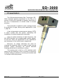
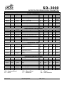
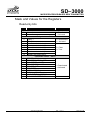
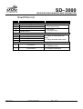
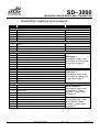
MICROPROCESSORBASED BRIX
TRANSMITTER
SD–3000
User Manual
Microprocessor-based Brix
Transmitter
MAN-EN-DE-SD3000
Rev.: 1.00-11
Introduction
Thank you for choosing our MICROPROCESSOR-BASED BRIX TRANSMITTER SD–
3000. To ensure its proper and efficient usage, it’s important to read this manual thoroughly to
understand how to operate the SD–3000, before putting it into operation.
About this Manual
1.
This manual should be delivered to the end user of the SD–3000.
2.
The contents of this manual are subject to change without notice.
3.
All rights reserved. No part of this manual may be reproduced in any form without the
written permission from DLG.
4.
The specifications contained herein are limited to standard models and do not cover
special products made by order.
5.
All precautions were taken on preparing this manual, in order to guarantee the quality of
its information.
CAUTION!
The instrument described in this technical user manual is a device suitable for
application in a specialized technical area. DLG supplied products are submitted to a strict
quality control process. However, industrial control electronic equipment can cause damage to
machinery or processes controlled by them in the event of any failure or improper operations
and may even endanger human lives. The user is responsible for setting and selecting values of
the parameters of the instrument. The manufacturer warns of the risks of incidents with injuries
to both people and goods, resulting from the incorrect use of the instrument.
Contents
INTRODUCTION............................................................................................ 3
CONTENTS ................................................................................................... 4
PRESENTATION ........................................................................................... 6
HOW TO SPECIFY ........................................................................................ 7
TYPICAL APPLICATIONS ............................................................................ 8
TECHNICAL SPECIFICATIONS.................................................................... 9
Input characteristics ............................................................................................ 9
Analog outputs characteristics ............................................................................ 9
General Characteristics .................................................................................... 10
DIMENSIONS .............................................................................................. 11
OPERATION................................................................................................ 12
Determining the Brix x Capacitance or Brix x Resistance curve................................ 13
INSTALLATION ........................................................................................... 14
Cable connection ...................................................................................................... 14
MECHANICAL INSTALLATION .................................................................. 16
SOFTWARE AND CONFIGURATION ......................................................... 17
Configuration ............................................................................................................. 20
Current Input ..................................................................................................... 20
Alarms .............................................................................................................. 22
Retransmission ................................................................................................. 24
Linearization ..................................................................................................... 26
Control .............................................................................................................. 27
Log.................................................................................................................... 28
Status Alarm.............................................................................................................. 30
Monitoring ................................................................................................................. 33
Trend ......................................................................................................................... 34
Communication ......................................................................................................... 35
Animation .................................................................................................................. 36
Configuring the Modbus RS-485 Communications Port ............................................ 37
MODBUS TABLE ........................................................................................ 39
Mask and Values for the Registers ........................................................................... 41
Read-only bits ................................................................................................... 41
Read/Write bits ................................................................................................. 42
Read/Write registers enumerations .................................................................. 43
Modbus relay activation and deactivation ................................................................. 45
Current channel engineering limits ............................................................................ 45
WARRANTY ................................................................................................ 46
NOTES ........................................................................................................ 47
SD–3000
MICROPROCESSOR-BASED BRIX TRANSMITTER
Presentation
The Microprocessor-based Brix Transmitter SD–
3000 transmits signals proportional to the Brix of a
mixture in which the electrode is inserted, where Brix is
the unit of measurement of soluble solids in sucrose
solutions.
The transmitter is applied in mass cooking process
for production of sugar, among other applications. (note
1, page 8).
It has a temperature measurement element (RTD)
in direct contact with the system, eliminating the
installation of another temperature transmitter.
Using a modern technique of radio frequency, the
SD–3000 provides two programmable analog signals:
Xs and Rs, which are proportional to the capacitance
and resistance of the cooked mass, respectively.
Moreover, its design eliminates the need for
cleaning the transmitter when it is used in batch cooking
process, greatly increasing the interval between
cleaning operations for continuous cooking.
The sensing part is built in a 316 stainless steel
casing and the electronic circuit is housed in aluminum
housing, making it suitable for mounting on brackets and
/ or flanges, within the process.
Page 6 of 48
User Manual SD-3000
Rev.: 1.00-11
All rights reserved to DLG Automação Industrial
SD–3000
MICROPROCESSOR-BASED BRIX TRANSMITTER
How to Specify
SD–3000 /
____ - ___
Useful length for measurement (B+30+C) – see Figure 1:
/L1 115 mm
/L2 165 mm
/L3 320 mm
/E
Special (specify)
- ___ Without flange
-F
With flange
User Manual SD-3000
Rev.: 1.00-11
All rights reserved to DLG Automação Industrial
Page 7 of 48
SD–3000
MICROPROCESSOR-BASED BRIX TRANSMITTER
Typical Applications
Degree Brix measurement in liquors, dissolved sugar, sugar massecuite A, B and C.
Note 1: other applications on request.
Page 8 of 48
User Manual SD-3000
Rev.: 1.00-11
All rights reserved to DLG Automação Industrial
SD–3000
MICROPROCESSOR-BASED BRIX TRANSMITTER
Technical Specifications
Input characteristics
Type
Parameter
Brix
Rod temp.
Current
10
DC current
0 ~ 20
4 ~ 20
± 0.5
Pt
0,1
0,1
Current
Input signal
Input impedance
A/D precision (FS)
Linearization
Min.
0
4
50
0
Degree Brix
Probe temp.
Degree Brix
PT-100
Max.
20
20
95
130
Comments
Unit
mA
@27MHz
RTD
Bx
ºC
Ω
±1
±1
uA
± 0,1
%
ºC
%
ºC
Analog outputs characteristics
Output Type
Range
Resolution
Output Impedance
Current
Current
0 ~ 20 mA
4 ~ 20 mA
4,8 uA
4,8 uA
750Ω max
750Ω max
User Manual SD-3000
Rev.: 1.00-11
All rights reserved to DLG Automação Industrial
Page 9 of 48
SD–3000
MICROPROCESSOR-BASED BRIX TRANSMITTER
General Characteristics
Parameter
Power
consumption
Input voltage
Operating
frequency
IP protection
Scan time
Scale
Modbus timeout
Alarms
Xs and Rs
linearization
Communication
Electronic unit
operating
temperature
Thermal stability
Relative humidity
Construction
Placement
Electrical
connection
Aprox. weight
Sampling time
Page 10 of 48
Characteristics
7,2 W
24 Vdc
27MHz
IP–65
150 ms
–30000 a +30000 in engineering units
Adjustable from 3 ms to 60 ms (3 ms multiples)
2 alarms, with 2 solid state relay outputs: max 240 Vca; 130 mA ca; Isol. 3750
Vca
50 interpolation points
2 RS-485 ports, with 1500 V isolation and transient protection filter
Configurable even, odd or no parity
Baud rates (bps): 9600, 19200, 38400, 57600 and 115200
Modbus RTU protocol
0 ºC - 75 ºC
±0,005% / °C span @ 25°C.
Up to 90%
Aluminum housing
AISI-316 stainless steel rod
Polyamide dielectric 6.6
Fast clamping connection flange
22AWG wire with fast clamping connectors
3 kg
6 samples per second
User Manual SD-3000
Rev.: 1.00-11
All rights reserved to DLG Automação Industrial
SD–3000
MICROPROCESSOR-BASED BRIX TRANSMITTER
Dimensions
Figure 1 – Scaling mount (dimensions in mm)
Dimensions
A (mm)
B (mm)
C (mm)
SD-3000/L1
300
40
45
SD-3000/L2
350
90
45
SD-3000/L3
505
90
200
User Manual SD-3000
Rev.: 1.00-11
All rights reserved to DLG Automação Industrial
Page 11 of 48
SD–3000
MICROPROCESSOR-BASED BRIX TRANSMITTER
Operation
The SD–3000 transmitter measures the Brix of the product around its contact area, based
on electrical principles. The electrical characteristics of a product depends on several factors,
including the Brix. Thus, measuring the difficulty of an electrical signal to go through the mass, it
is possible to determine the degree Brix.
The SD–3000 is an instrument that measures two electrical quantities, resistance and
capacitance. The RS channel is proportional to the resistance and the other channel, XS, is
proportional to the capacitance.
The two channels can be used in control applications. However, experience shows that the
channel XS is more immune to variations of impurities.
Figure 2 – SD-3000 operation.
Note: illustrative figure which may differ according to the process.
The
transmitter channels
obey a linear variation with
the resistance
and
capacitance, but these quantities do not obey a linear function when compared with the
degree Brix. The SD–3000 is able to linearize this curve to indicate the value in Brix and its
main characteristic is repeatability.
The most important feature is the repeatability, i.e., if a specific control operation point in a
process has a specific current in mA (in resistance or capacitance), this value will be repeatable
and may be used always in the process, including other batches.
The SD–3000 performs linearization in order to estimate the Brix. A specific linearization
must not be used in other processes different than the one that was used to calculate the
linearization parameters. Once a specific linearization RS x Brix or XS x Brix is obtained few
changes should occur in the process.
Page 12 of 48
User Manual SD-3000
Rev.: 1.00-11
All rights reserved to DLG Automação Industrial
SD–3000
MICROPROCESSOR-BASED BRIX TRANSMITTER
Determining the Brix x Capacitance or Brix x
Resistance curve
The SD–3000 has two signal linearization tables, with 50 points each. Using this feature,
we can estimate the Brix of the measured mass. Therefore, it is necessary to use a precision
refractometer as reference for the sample.
Initially, a table must be created. This table must have annotations of the RS, XS and Brix
values. The DLGTools software has this feature which automates the linearization process (see
Software and configuration Configuration LOG).
Start collecting mass samples and at the moment the sample is collected, record the value
of channels RS and XS. Keep the sample and measure its Brix in the refractometer. Repeat this
step for different values of Brix.
Once the table is filled, a linearization curve is determined.
Some care must be taken when the samples are collected:
• The sample should be collected as close as possible to the SD–3000 transmitter;
• Before collecting the sample, check whether there is a significant variation in the
RS and/or XS channels;
• Make sure that the collected sample represents the product that is being
analyzed by the SD–3000 transmitter;
• Take special care with the collecting pipes. They can accumulate products that
may be contaminated or accumulate products from previous samples, which can
invalidate the sampling process;
• Pay attention to the sample collecting time. It is good practice to use the values
of XS and RS only after the sample is collected;
• It is also recommended to repeat this procedure three times, in order to eliminate
discrepancies.
User Manual SD-3000
Rev.: 1.00-11
All rights reserved to DLG Automação Industrial
Page 13 of 48
SD–3000
MICROPROCESSOR-BASED BRIX TRANSMITTER
Installation
Cable connection
Pin
1
2
3
4
5
6
7
8
Page 14 of 48
CN1
Function
Positive, current input
Negative, current input
Positive, RS-485 communication port 1
Negative, RS-485 communication port 1
Shield, RS-485 communication port 1
Positive, current output 1
GND current outputs 1 and 2
Positive, current output 2
Cable color
Red
Light Brown
Blue
Grey
Green
Yellow
Dark Brown
White
User Manual SD-3000
Rev.: 1.00-11
All rights reserved to DLG Automação Industrial
SD–3000
MICROPROCESSOR-BASED BRIX TRANSMITTER
CN2
Function
Pin
1
2
3
4
5
6
7
8
Power +24Vdc
Power GND
Housing GND
Normally open (NO) output relay 1
Common relay 1
Normally open (NO) output relay 2
Common relay 2
Not used
Cable color
Red
Light Brown
Green
Blue
Grey
Yellow
White
-
Pin
1
2
3
4
5
CN3
Function
Output (HMI) Power +24Vdc
Output (HMI) Power GND
Positive, RS-485 communication port 2
Negative, RS-485 communication port 2
Shield RS-485 communication port 2
Color cable
Red
Black
Blue
White
Dark Brown
User Manual SD-3000
Rev.: 1.00-11
All rights reserved to DLG Automação Industrial
Page 15 of 48
SD–3000
MICROPROCESSOR-BASED BRIX TRANSMITTER
Mechanical Installation
The SD–3000 must be installed directly to the process in which Brix measurement is to
done. In baking pans (sugar manufacturing) the SD–3000 must be installed underneath or on
the side taking care to install it in a location where it is ensured that the transmitter will measure
a homogeneous mass.
It is recommended to keep a distance of 0.5 m between the SD–3000 and any metal parts
(including paddle stirrer if any). This ensures that the measurement principle of the transmitter
will not be influenced by proximity to metal parts.
The SD–3000 should never be installed above the calender or where there is the
possibility of bubble formation that may cause errors in measurement.
*Figure 3 - Transmitter position in sugar cooking pot (vaccum)
*Note: Figure 3 is an illustrative example, not having a real scale.
Page 16 of 48
User Manual SD-3000
Rev.: 1.00-11
All rights reserved to DLG Automação Industrial
SD–3000
MICROPROCESSOR-BASED BRIX TRANSMITTER
Software and Configuration
*Note: Before configuring the SD–3000, make sure that the equipment has been operating
for approximately 20 minutes.
The SD–3000 is configured by DLGTools.
After DLGTools is opened, click in the icon
devices in the Modbus network.
ONLINE/OFFLINE to find the SD–3000
User Manual SD-3000
Rev.: 1.00-11
All rights reserved to DLG Automação Industrial
Page 17 of 48
SD–3000
MICROPROCESSOR-BASED BRIX TRANSMITTER
Select the correct SD–3000 and click in
from the SD–3000.
Page 18 of 48
. DLGTools will upload all parameters
User Manual SD-3000
Rev.: 1.00-11
All rights reserved to DLG Automação Industrial
SD–3000
MICROPROCESSOR-BASED BRIX TRANSMITTER
In the configuration screen it is possible to parameterize all SD–3000 registers.
The DLG Tools Explorer window can select all the configuration and operation functions of
the SD–3000.
Configuration: Configure all SD–3000 parameters,
as
current
inputs,
alarms,
retransmission,
linearization, control and sample logs;
Status Alarm: Monitors the alarm statuses and
whether the output relays are triggered or not;
Monitoring:
Monitors
all
SD–3000
Modbus
registers, automatically or manually;
Trend: Display the XS, RS, linearized XS, linearized
RS, temperatures, current input, rod temperature
and internal temperature.
Communication: Display RS-485 port configuration
parameters and the UPLOAD and DOWNLOAD
commands.
Animation: Graphical resources for representing the inputs.
User Manual SD-3000
Rev.: 1.00-11
All rights reserved to DLG Automação Industrial
Page 19 of 48
SD–3000
MICROPROCESSOR-BASED BRIX TRANSMITTER
Configuration
Current Input
Page 20 of 48
User Manual SD-3000
Rev.: 1.00-11
All rights reserved to DLG Automação Industrial
SD–3000
MICROPROCESSOR-BASED BRIX TRANSMITTER
Parameters:
•
Offset: Adds an offset value to the value read from the current input. Example: If the
reading is 10.00 and the offset is 1.00 then the value shown in the channel will be
10.00 + 1.00 = 11:00
•
Decimal Point: Determines the number of places after the comma, and may be from
0 up to 3.
Example: 10.000, 10.00, 10.0 ou 10.
•
Un Eng Max: Determines what will be the value displayed in the current channel
when the input is equal to 20 mA.
•
Un Eng Min: Determines what will be the value displayed in the current channel
when the input is equal to 0 mA.
The configuration parameters for the current input determine which value will be displayed
in the current channel.
Example:
Offset
Decimal Point
Un Eng Max.
Un Eng Min.
= 1,00
=2
= 30.00
= 3,00
When the input is 10 mA, the indication will be 16.50.
User Manual SD-3000
Rev.: 1.00-11
All rights reserved to DLG Automação Industrial
Page 21 of 48
SD–3000
MICROPROCESSOR-BASED BRIX TRANSMITTER
Alarms
Parameters:
•
Variable: Defines which variable will be associated to alarm 1 or 2. The possible
variables are:
Page 22 of 48
XS;
RS;
Linearized XS;
Linearized RS;
Current Input;
Rod temperature.
User Manual SD-3000
Rev.: 1.00-11
All rights reserved to DLG Automação Industrial
SD–3000
MICROPROCESSOR-BASED BRIX TRANSMITTER
•
Alarm Condition: Defines which the condition mode of alarms 1 and 2 is. The
possible modes are:
•
Value of Low: operates when the input value falls below the Set Point.
Valor of High: operates when the input value goes above the Set Point.
Differential: operates when the input value lies outside the range defined by
Set Point and Hysteresis, where Set Point is the center of the range and
Hysteresis defines its upper and lower limits.
Inverted Differential: operates when the input value lies inside the range
defined by Set Point and Hysteresis, where Set Point is the center of the
range and Hysteresis defines its upper and lower limits.
Inoperative: disables the alarm.
Hysteresis: For each alarm condition type Hysteresis has a different function:
Value of Low: Hysteresis defines an offset to disable the alarm. The alarm
will be disabled when the input value is greater than the Set Point plus
Hysteresis.
Value of High: Hysteresis defines an offset to disable the alarm. The alarm
will be disabled when the input value is less than the Set Point plus
Hysteresis.
Differential: Hysteresis defines high and low limits for alarm operation. Set
Point is the center of the range and Hysteresis defines upper and lower
limits. Example: Set Point 5.00 and Hysteresis 1.00 defines a range from
4.00 to 6.00, and the alarm is enabled when the input value is OUTSIDE
this range.
Inverted Differential: Hysteresis defines high and low limits for alarm
operation. Set Point is the center of the range and Hysteresis defines upper
and lower limits. Example: Set Point 5.00 and Hysteresis 1.00 defines a
range from 4.00 to 6.00, and the alarm is enabled when the input value is
INSIDE this range.
•
Time Delay: Sets a timer to enable the alarm. If the input is within the alarm range
the timer is triggered and when the specified time elapses the alarm will be enabled.
If the input value leaves the alarm range the timer will reset and will trigger again
when the input value lies inside the alarm range.
•
Set Point: Reference value for alarm activation.
•
Select Relay: Defines which relay will be activated by the alarm.
User Manual SD-3000
Rev.: 1.00-11
All rights reserved to DLG Automação Industrial
Page 23 of 48
SD–3000
MICROPROCESSOR-BASED BRIX TRANSMITTER
Retransmission
Parameters:
•
Variable: This parameter defines which variable will be associated with
retransmission 1 or 2.
The possible variables are:
Page 24 of 48
XS;
RS;
Linearized XS;
Linearized RS;
Current channel;
Rod temperature.
User Manual SD-3000
Rev.: 1.00-11
All rights reserved to DLG Automação Industrial
SD–3000
MICROPROCESSOR-BASED BRIX TRANSMITTER
•
Output Range: Defines the retransmission ranges:
0 ~ 20 mA and 0 ~ 10 Volts
4 ~ 20 mA and 2 ~ 10 Volts
•
Scale: Defines the scales associated with retransmission:
Engineering: uses Un Max Eng and Un Min Eng as retransmission limits.
Only Current channel and Rod temperature can be selected in this case.
Example: if the current channel is being retransmitted and the configured
engineering units are from 0.00 to 30.00 then input 0.00 is retransmitted as
0 mA (or 4 mA) and input 30.00 is retransmitted as 20 mA.
Limit: uses the configured limits (High Limit and Low Limit) for
retransmission. Any channel may be selected.
Example: if the current channel is being retransmitted and the configured
engineering units are from 0.00 to 30.00, and the configured limits are from
10.00 to 20.00, then input 10.00 is retransmitted as 0 mA (or 4 mA) and
input 20.00 is retransmitted as 20 mA. The output is limited to the selected
range keeping proportionality with the input.
User Manual SD-3000
Rev.: 1.00-11
All rights reserved to DLG Automação Industrial
Page 25 of 48
SD–3000
MICROPROCESSOR-BASED BRIX TRANSMITTER
Linearization
The SD–3000 has 2 linearization tables (XS and RS), with 50 points each. Linearization is
enabled when bit 1 from the SD–3000 control register (address 40035) is set.
The number of linearization steps should be chosen as follows:
1 - Edit columns LINI_ and LINO_ inserting the desired number of rows.
2 - After the last row LININ_ and LINO_ must be zero.
3 - The first LINI_ value is not editable and is always zero.
4 - LINI_ values cannot lie outside the RS (0 to 15000) and XS (0 to 1500) limits.
Page 26 of 48
User Manual SD-3000
Rev.: 1.00-11
All rights reserved to DLG Automação Industrial
SD–3000
MICROPROCESSOR-BASED BRIX TRANSMITTER
Control
Parameters:
• XS Goal: Set point value relative to the phase difference in which the SD–3000 has
constant control.
• Phase Filter: Filter value applied to the SD–3000 phase control signal.
• Phase Error: Maximum error allowed to phase control considering the set point
value fixed in XS Goal.
User Manual SD-3000
Rev.: 1.00-11
All rights reserved to DLG Automação Industrial
Page 27 of 48
SD–3000
MICROPROCESSOR-BASED BRIX TRANSMITTER
Log
This feature is useful to create a linearization table, with the samples measured in a
laboratory.
•
•
•
•
•
Page 28 of 48
Collect the sample and click in
.
Put an identification number on the sample and in the TAG column in the table.
Send the sample to the laboratory.
After receiving the results from the laboratory fill the table.
Repeat this step for the number of samples wanted.
User Manual SD-3000
Rev.: 1.00-11
All rights reserved to DLG Automação Industrial
SD–3000
MICROPROCESSOR-BASED BRIX TRANSMITTER
To create a new file:
•
•
Click in
.
Give a name to the file and save it.
To use an existent file:
•
Click in
•
Selected the file and click in
.
(Open).
It is possible to export data to Microsoft Excel, clicking in
name to the new file.
User Manual SD-3000
Rev.: 1.00-11
All rights reserved to DLG Automação Industrial
and selecting a
Page 29 of 48
SD–3000
MICROPROCESSOR-BASED BRIX TRANSMITTER
Status Alarm
This feature allows monitoring of the relay activation statuses, based on the alarm
configuration. It is also possible to reset or force the relay activation.
Page 30 of 48
User Manual SD-3000
Rev.: 1.00-11
All rights reserved to DLG Automação Industrial
SD–3000
MICROPROCESSOR-BASED BRIX TRANSMITTER
This feature allows monitoring the alarm activation statuses.
User Manual SD-3000
Rev.: 1.00-11
All rights reserved to DLG Automação Industrial
Page 31 of 48
SD–3000
MICROPROCESSOR-BASED BRIX TRANSMITTER
This feature allows monitoring the transmitter statuses.
Page 32 of 48
User Manual SD-3000
Rev.: 1.00-11
All rights reserved to DLG Automação Industrial
SD–3000
MICROPROCESSOR-BASED BRIX TRANSMITTER
Monitoring
This feature monitors the whole Modbus table, manually or automatically.
By clicking in
the Modbus table is scanned once.
By clicking in
the table is scanned continuously, with period defined in Tools >
Communication > Scan > Scan Period. The scan period can be from 0.1 to 5 seconds. To stop
scanning, click in
.
Data can be exported to Microsoft Excel by clicking in
name to the new file.
User Manual SD-3000
Rev.: 1.00-11
All rights reserved to DLG Automação Industrial
and defining a
Page 33 of 48
SD–3000
MICROPROCESSOR-BASED BRIX TRANSMITTER
Trend
This feature displays a graphical representation of the SD–3000 inputs.
•
Set the sampling time, which can be specified in:
•
Click in
•
Click in
Page 34 of 48
Minutes
Hours
Days
and create a new file or open an existent one.
.
User Manual SD-3000
Rev.: 1.00-11
All rights reserved to DLG Automação Industrial
SD–3000
MICROPROCESSOR-BASED BRIX TRANSMITTER
Communication
This feature uploads the SD-3000 registers to DLGTools or downloads the DLGTools
registers to the SD-3000.
• Status Communication:
Port Connected: indicates to which RS-485 port in the SD-3000 that
DLGTools is connected to.
Status Port: indicates if the port is in NORMAL or RESET mode.
Port last write: indicates which SD-3000 port last received configuration
parameters.
• Current Parameters Port 1 and 2: indicates how the RS-485 ports are configured.
User Manual SD-3000
Rev.: 1.00-11
All rights reserved to DLG Automação Industrial
Page 35 of 48
SD–3000
MICROPROCESSOR-BASED BRIX TRANSMITTER
Animation
This feature allows animating all analog registers from the Modbus table using graphical
objects.
Page 36 of 48
User Manual SD-3000
Rev.: 1.00-11
All rights reserved to DLG Automação Industrial
SD–3000
MICROPROCESSOR-BASED BRIX TRANSMITTER
Configuring the Modbus RS-485 Communications
Port
In the device search screen, DLGTools can configure the RS-485 communications port
parameters of the DLG devices.
User Manual SD-3000
Rev.: 1.00-11
All rights reserved to DLG Automação Industrial
Page 37 of 48
SD–3000
MICROPROCESSOR-BASED BRIX TRANSMITTER
Clicking over the desired device and then in
, the communications
configuration screen will be opened. In this screen it is possible to configure:
•
ID: this is the device Modbus address, ranging from 1 to 255.
•
Baud Rate: Defines the baud rate, which can be: 9600, 19200, 38400, 57600 or
115200 bps.
•
Paridade: Defines how parity checking is done: even parity, odd parity or no parity.
•
Atraso resposta: Defines a delay between the equipment receiving the Modbus
request and sending the Modbus response. The delay can range from 10 ms to 100
ms.
After the parameters are set, click in
Page 38 of 48
to send them to the SD–3000.
User Manual SD-3000
Rev.: 1.00-11
All rights reserved to DLG Automação Industrial
SD–3000
MICROPROCESSOR-BASED BRIX TRANSMITTER
CA
CM
CXSV
CRSV
CXSL
CRSL
CCor
TEMP
STA
RES
STR
STS
TEMPI
RSA
RESERVED
Goal channel
XS channel volts
RS channel volts
XS channel linearized
RS channel linearized
Current channel
PT100 temperature
Alarm status
RESERVED
Relay status
Transmitter status
Internal temperature
Alarm reset
0
0x0F
Min
Mnemonic
0
1
2
3
4
5
6
7
8
9
10
11
12
13
Description
Max
Offset
40001
40002
40003
40004
40005
40006
40007
40008
40009
40010
40011
40012
40013
40014
Limits
Default
Address
Modbus Table
T
y
p
e
Read/
WriteRetentive
/NonRetentive
R
R
R
R
R
R
R
R
R
R
R
R
R
0
US
SS
SS
SS
SS
SS
SS
US
US
US
US
US
SS
US
R/W NR
Communications Configuration
40015
40016
40017
40018
40019
40020
40021
14
15
16
17
18
19
20
END
BRC1
PARC1
TOUTC1
BRC2
PARC2
TOUTC2
Address
Channel 1 baud rate
Channel 1 parity
Channel 1 timeout
Channel 2 baud rate
Channel 2 parity
Channel 2 timeout
1
4
2
10
4
2
10
247
7
2
100
7
2
100
0
3
0
10
3
0
10
US
US
US
US
US
US
US
R/W
R/W
R/W
R/W
R/W
R/W
R/W
R
R
R
R
R
R
R
0
20000
0
3
30000
30000
30000
4
-30000
-30000
-30000
0
SS
SS
SS
US
R/W
R/W
R/W
R/W
R
R
R
R
Engineering
40022
40023
40024
40025
21
22
23
24
OSETMA
ENGH
ENGL
PDMA
mA Offset
Engineering High MA
Engineering Low MA
Decimal point MA
User Manual SD-3000
Rev.: 1.00-11
All rights reserved to DLG Automação Industrial
Page 39 of 48
SD–3000
MICROPROCESSOR-BASED BRIX TRANSMITTER
Alarm Configuration
40026
40027
40028
40029
40030
40031
40032
40033
40034
25
26
27
28
29
30
31
32
33
CTRLA
CAL
DAL1
DAL2
HAL1
HAL2
SPAL1
SPAL2
MASRL
Alarm control
Alarm condition
Alarm 1 delay
Alarm 2 delay
Alarm 1 hysteresis
Alarm 2 hysteresis
Alarm 1 set point
Alarm 2 set point
Alarm relay mask
0x55
0
0
0
0
0
0
0
0
0x2000
0
US
0x44
0
US
10
0
US
10
0
US
30000
0
US
30000
0
US
30000 -30000 SS
30000 -30000 SS
0x0F
0
US
R/W
R/W
R/W
R/W
R/W
R/W
R/W
R/W
R/W
R
R
R
R
R
R
R
R
R
0x0F
0x2000
30000
30000
30000
30000
R/W
R/W
R/W
R/W
R/W
R/W
R
R
R
R
R
R
Retransmission Configuration
40035
40036
40037
40038
40039
40040
40041
40042
34
35
36
37
38
39
40
41
TRET
CRET
LRLXS
LRHXS
LRLRS
LRHRS
Retransmission type
Retransmission channel
CH1 low retransmission limit
CH1 high retransmission limit
CH2 low retransmission limit
CH2 high retransmission limit
RESERVED
RESERVED
0
0x55
0
0
0
0
0
0
0
0
0
0
US
US
SS
SS
SS
SS
Linearization Tables
40043
40093
40143
40193
40243
40244
40245
40246
40247
40248
40249
40250
40251
42-91
92141
142191
192241
242
243
244
245
246
247
248
249
250
XS output value for
LINOXS0i
linearization point i
XS input value for linearization
LINIXS01
point i
RS output value for
LINORS01
linearization point i
RS input value for linearization
LINIRS01
point i
CTRL
SD3000 control
TMASS
MXS
DA1
DA2
DA3
DA4
FILD
ERRD
US = Unsigned Short
W = Write
Page 40 of 48
0
30000
0
30000
0
30000
0
30000
0
SS
R/W R
0
0x0F
0
US
R/W R
0
0
0
0
0
0
0
0
US
US
US
US
US
US
US
US
R/W
R/W
R/W
R/W
R/W
R/W
R/W
R/W
Calibrations (password needed)
Mass type
0
0x7FFF
Goal XS
0
15000
DA1
1000
1500
DA2
0
1500
DA3
937
1500
DA4
600
1500
Phase Drift Filter
30
100
Phase Drift Error
30
100
SS = Signed Short
R = Retentive
-30000 SS
0
SS
R/W R
-30000 SS
R/W R
R = Read
NR = Non-retentive
User Manual SD-3000
Rev.: 1.00-11
All rights reserved to DLG Automação Industrial
R/W R
R
R
R
R
R
R
R
R
SD–3000
MICROPROCESSOR-BASED BRIX TRANSMITTER
Mask and Values for the Registers
Read-only bits
Bit
0
1
Function
Alarm status - 40009
Alarm 1
Alarm 2
Comments
0 = Deactivated
1 = Activated
Relay status – 40011
0
1
8
9
10
11
12
13
0
1
2
3
4
5
6
7
8
9
Relay 1
0 = Deactivated
1 = Activated
Relay 2
Alarm 1 activated relay 1
Alarm 1 activated relay 2
Alarm 2 activated relay 1
0 = False
1 = True
Alarm 2 activated relay 2
Modbus activated relay 1
Modbus activated relay 2
Transmitter status – 40012
PROBE_LOCK
PROBE_CONTROL_OFF
PROBE_DEF_MINOR
PROBE_DEF_MAJOR
0 = Deactivated
PROBE_LOOP
1 = Activated
RESERVED
CS5524 ERROR
EEPROM_ERROR
LINEARIZATION_ERROR
PASSWORD FEEDBACK
User Manual SD-3000
Rev.: 1.00-11
All rights reserved to DLG Automação Industrial
Page 41 of 48
SD–3000
MICROPROCESSOR-BASED BRIX TRANSMITTER
Read/Write bits
Bit
0
1
2
3
0
1
2
3
0
1
Page 42 of 48
Comments
Function
Relay activation/deactivation – 40014
Deactivate relay 1
0 = No action
1 = Deactivates relay
Deactivate relay 2
Activate relay 1
0 = No action
1 = Activates relay
Activate relay 2
Alarm 1 and 2 masks – 40034
Alarm 1 relay 1
0 = Relay not associated with
Alarm 1 relay 2
alarm
Alarm 2 relay 1
1 = Relay associated with alarm
Alarm 2 relay 2
Control – 40243
0 = Enables control
XS control
1 = Disables control
0 = Disables linearization
Linearization
1 = Enables linearization
User Manual SD-3000
Rev.: 1.00-11
All rights reserved to DLG Automação Industrial
SD–3000
MICROPROCESSOR-BASED BRIX TRANSMITTER
Read/Write registers enumerations
Value
3
4
5
6
7
Comments
Function
Baud rate – 40016 and 40019
9600
19200
38400
57600
115200
Parity – 40017 and 40020
0
1
2
Even
Odd
None
Alarm type – 40026
0x00
0x01
0x02
0x03
0x04
0x05
0x06
0x10
0x20
0x30
0x40
0x50
0x60
Disabled
XS channel
RS channel
Linearized XS channel
Linearized RS channel
Current channel
PT100 temperature
XS channel
RS channel
Linearized XS channel
Linearized RS channel
Current channel
PT100 temperature
Alarm type 1
The register value must
be the sum of “alarm type
1” and “alarm type 2”.
Alarm type 2
The register value must
be the sum of “alarm type
1” and “alarm type 2”.
Alarm condition – 40027
0
1
2
3
4
0
8
16
24
32
Minimum value
Maximum value
Differential
Differential inverted
Disabled
Minimum value
Maximum value
Differential
Differential inverted
Disabled
Alarm condition 1
The register value must
be the sum of “alarm
condition 1” and “alarm
condition 2”.
Alarm condition 2
The register value must
be the sum of “alarm
condition 1” and “alarm
condition 2”.
User Manual SD-3000
Rev.: 1.00-11
All rights reserved to DLG Automação Industrial
Page 43 of 48
SD–3000
MICROPROCESSOR-BASED BRIX TRANSMITTER
0x00
0x01
0x02
0x03
0x00
0x10
0x20
0x30
0x00
0x01
0x02
0x03
0x04
0x05
0x06
0x10
0x20
0x30
0x40
0x50
0x60
0
1
2
Page 44 of 48
PV retransmission type – 40035
0 – 20 mA or 0 – 10 V retransmission based on span and
engineering zero
0 – 20 mA or 0 – 10 V retransmission based on minimum
and maximum limits
4 – 20 mA or 2 – 10 V retransmission based on span and
engineering zero
4 – 20 mA or 2 – 10 V retransmission based on minimum
and maximum limits
0 – 20 mA or 0 – 10 V retransmission based on span and
engineering zero
0 – 20 mA or 0 – 10 V retransmission based on minimum
and maximum limits
4 – 20 mA or 2 – 10 V retransmission based on span and
engineering zero
4 – 20 mA or 2 – 10 V retransmission based on minimum
and maximum limits
Retransmitted channel – 40036
Disabled
XS channel
RS channel
Linearized XS channel
Linearized RS channel
Current channel
PT100 temperature
XS channel
RS channel
Linearized XS channel
Linearized RS channel
Current channel
PT100 temperature
Mass type – 40244
A or B mass
Free
Calibration
Retransmission type 1
The register value must be
the sum of “retransmission
type 1” and “retransmission
type 2”.
Retransmission type 2
The register value must be
the sum of “retransmission
type 1” and “retransmission
type 2”.
Retransmitted channel 1
The register value must be
the sum of “retransmitted
channel 1” and
“retransmitted channel 2”.
Retransmitted channel 2
The register value must be
the sum of “retransmitted
channel 1” and
“retransmitted channel 2”.
User Manual SD-3000
Rev.: 1.00-11
All rights reserved to DLG Automação Industrial
SD–3000
MICROPROCESSOR-BASED BRIX TRANSMITTER
Modbus relay activation and deactivation
Relay activation/deactivation - 40014
Value
Action
1
Deactivate relay 1
2
Deactivate relay 2
4
Activate relay 1
8
Activate relay 2
If the transmitter receives an activation and deactivation request for the same relay, only
the deactivation request is processed.
It is only possible to activate or deactivate a relay from a Modbus request only if the relay
is not associated with an alarm, otherwise the request is discarded.
Current channel engineering limits
The SD–3000 transmitter has a current input channel that may be used for any purpose
and its engineering limits are described below:
Channel
Current
Eng Max
30000
Eng Min
-30000
Comments
Configurable by the current input
User Manual SD-3000
Rev.: 1.00-11
All rights reserved to DLG Automação Industrial
Page 45 of 48
SD–3000
MICROPROCESSOR-BASED BRIX TRANSMITTER
Warranty
The manufacturer assures to the equipment owners, identified by the purchase invoice,
warranty of 1 (one) year as follows:
1 - The warranty period begins on the data of the invoice issue.
2-
Within the warranty period, the labor and parts used for repairing damage occurred in
normal use are free.
3-
For repairs, send the equipment along with the shipping invoices to our factory in
Sertãozinho, São Paulo state, Brazil. DLG’s address is available at the end of this
manual.
4 - The owner is responsible for transportation costs and risks.
5-
Warranty will be automatically suspended if changed are made to the equipment by
personnel not authorized by DLG, defects caused by mechanical shock, exposure to
conditions unfit for use or tampering with the product.
6-
DLG disclaims any charge relating to unauthorized repairs or replacements due to
failures caused by agents external to the equipment, the improper use of them and as a
result of unforeseeable circumstances or major forces.
7-
The DLG ensures full operation of the equipment described herein and all existing
operations.
Page 46 of 48
User Manual SD-3000
Rev.: 1.00-11
All rights reserved to DLG Automação Industrial
Notes
DLG Automação Industrial Ltda.
Rua José Batista Soares, 53
Distrito industrial – 14176-119
Sertãozinho – São Paulo – Brasil
Fone: +55-16-3513-7400
www.dlg.com.br
Rev: 1.00-11
MICROPROCESSOR-BASED BRIX TRANSMITTER
SD–3000
DLG reserves the right to change this manual contents
without notice in order to keep updating it with potential product
developments.