1
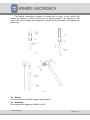
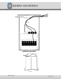
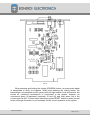
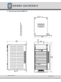
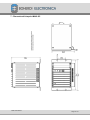
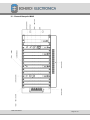
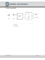
INTERNAL ARC MONITOR SYSTEM
DESCRIPTIVE AND OPERATIONAL HANDBOOK
MAI2 User Manual
Page 1 / 27
Code: EB4-056 rev0
INDEX:
1 - Introduction.
2 - Technical data.
2.1 - MAI2.
2.2 - MO2.
2.3 - Testing.
3 - Installation.
3.1 - optical fibers.
3.2 - Wiring.
3.3 - Assembly.
4 - Starting up the system.
4.1 - Configuration and tests.
4.2 - Calibration.
5 - System description.
5.1 Composition.
5.2 Operation.
5.3 Precautions.
5.4 Interpretation of numeric indications.
6 - Dimensional blueprint MAI2-CC.
7 - Dimensional blueprint MAI2-SC.
8 - Blocks diagram MAI2-CC-TR.
9 - Blocks diagram MAI2-CC-TC .
10 - General blueprint MAI2.
11 - Dimensional blueprint MO2.
12 - Blocks diagram MO2.
13 - Typical wiring MAI2/MO2.
MAI2 User Manual
Page 2 / 27
Code: EB4-056 rev0
1 - Introduction
The internal arcs by accident, bad contacts and other contingencies causing
electrical failures are one of the most severe problems for low, middle and high
voltage electrical switchgears.
The worst effects of these arcs are serious injuries or death, extended
damage to installations and rendering the equipment unavailable for prolonged
periods of time.
The preventive actions must be based on knowledge of the internal arc
phenomena, and measures to overcome such event.
To summarize, the following points can be expressed as the basic criteria for
the electrical switchgears safety:
1. - Preventive measures in the design.
2. - Limit the time of the arc.
3. - Toleration of the increment in pressure.
4. - Toleration of the increment in temperature.
A good design shall include a sum of mechanisms to prevent the occurrence
of internal arcs; or to minimize its effect in the personnel and the equipment.
In general, three stages can be established in the internal arc processes:
1. - Compression stage: production of a fast overpressure without gas
emissions.
2. - Emission stage: Gases are generated.
3. Fusion
stage:
Solid
material
is
thermally
affected.
To prevent risks of overpressure and material fusion, the activated
mechanisms shall interrupt the arc in less than 50ms (milliseconds).
If we consider that the overcurrent protection response time for Medium
Voltage is in the order of a second, is easy to conclude that to protect the personnel
it is necessary to mechanically reinforce the switchgear, adding a considerable cost.
That is why BOHERDI ELECTRÓNICA has developed its MAI2 Internal arc
Monitor, an intrinsic protection, independent of adjustments and coordination of other
protections, with its own detection and activation times in the order of 1 millisecond,
which added to the breaker actuation time, represents a value below 50
milliseconds, fundamental to limit or prevent any material damage and to protect the
personnel with an inferior cost of mechanically reinforce the electric switchgears; and
with a higher efficiency.
BOHERDI ELECTRÓNICA system is based in the optical detection of the arc,
with luminescence sensors, sensitive to quantities superior of 1000lux, and
transmitted via optical fibers to a photo-transistor that transforms the light signal in
electric signal.
MAI2 User Manual
Page 3 / 27
Code: EB4-056 rev0
The optical fiber transmission immunize the system from interferences
generated by the operation of other equipment in its proximity. All components in
the system are immunized and tested against electromagnetic noise and
interference, eliminating the risk of untimely operation (activation) of the monitor,
which is a characteristic problem of systems transmitting the signal via cables.
Besides its high speed operation, the system presents other advantageous
characteristics:
-Uses plastic optical fibers, easy to install since allows a curvature radio
higher or similar to 25mm.
- The light captor is easy to apply to the end of the fiber, since this one has a
thread and a pressure nut, by which is firmly attached.
-Preparation for the end of the fiber does not require special tools, only
common, good cutting tools.
-This allows for the easy change of a light captor in the area where the arc
was produced, without needing to change the entire length of the fiber installed to
the monitor.
-Built in modules with plug-in boards, easy to replace and exchange.
-The over-current sensor is an extractable board in the monitor. It has an
automatic short-circuit connector input, ending in a pass terminal. This allows for
replacing the board without affecting the functioning of other working protections.
The BOHERDI ELECTRÓNICA (MAI2) Internal arc Monitor has been
successfully tested under the IEC 60068-2-38 & IEC 60255-5 norms and evaluated
with satisfaction in an electric board internal arc test conducted by CEPEL.
MAI2 User Manual
Page 4 / 27
Code: EB4-056 rev0
2 - Technical Data
2.1 - Models:
There are two internal arc Monitors, each with to possible versions:
MAI2-CC: This model includes an overcurrent sensor that detects not only the
electric arc, but also the presence of overcurrent. The overcurrent
signal is internally propagated and retransmitted via optical fiber so it
can be used together with arc detection to generate the trip signals.
MAI2-SC: This model does not include an overcurrent sensor. However, it can
receive and use the overcurrent information generated in monitor
model MAI2-CC.
The versions for each models are the following:
MAI2-XX-TR: The equipment includes a tripping board using transistors as the
switching element, appropriate with equipment with DC opening
coils.
MAI2-XX-TC: The equipment includes a tripping board using triacs as the
switching element, appropriate with equipment with AC opening
coils.
2.1.1 – General characteristics of MAI2:
Characteristics:
Brand
Model
Functioning type
Service type
Boherdi Electrónica
MAI2-SC , MAI2-CC
Electronic
Permanent
optical Inputs:
With numeric indication
Overcurrent Signal, arc repetition
8
3
optical outputs:
arc light repetition
Overcurrent signal repetition
1
1
Tripping output (TC version)
Quantity
4
Tripping output (TR version)
Quantity
5
MAI2 User Manual
Page 5 / 27
Code: EB4-056 rev0
Tripping Optotransistor (TC version)
Quantity
1
Tripping Alarm
Quantity
2 NO
Overcurrent Alarm (mod. CC)
Quantity
1 NOA
Transducer current failure alarm
Quantity
(mod. CC)
1 NC
Power failure alarm
Quantity
1 NC
Visible Indicators:
Power supply on
Monitor in alert status
Flash detection (1 to 8)
Overcurrent detection
Tripping
Yellow Led
Decimal point ON in led display
Numeric display
Green Led
Red Led
Controls at front:
Arc flash and tripping reset
Overcurrent reset (mod. CC)
Overcurrent simulation (mod. CC)
Push button
Push button
Push button
Internal board configuration:
Current jumper
Inhibition jumper
Receptor jumper
Threshold adjustment>> (mod. CC)
With/ Without
YES / NO
Current / Light
Preset
Dimensions:
Height:
Width:
Depth:
156mm
308mm (Mod. CC) 231mm (Mod. SC)
201mm
2.1.2 – MAI2 Electrical characteristics :
Characteristics
Power voltages
Maximum consumption
Admissible environmental temperature
48, 110, 220 Vcc, 220 Vca
15W
-12...60ºC
MAI2 User Manual
Page 6 / 27
Code: EB4-056 rev0
Tripping outputs (TC version)
Maximum current (permanent)
Maximum current (200 ms)
Maximum start current
Minimum maintenance current
Leakage current (@220Vca 50Hz)
Maximum voltage
1 A.
5 A.
10 A.
50 mA
8 mA
400Vdc/250Vca
Tripping outputs (TR version)
Maximum current (permanent)
Maximum start current
Leakage current (200Vdc)
Maximum voltage
5 A.
10 A.
0.5mA
250Vdc
Tripping Optotransistor (TC version)
Admissible max. current
Admissible max. votage
80mA
250V
Tripping alarm (relay)
Breaking capacity max. 220Vac
Breaking capacity max. 220Vdc
5 A.
125mA
Others Alarms (optotransistor)
Admissible max. current
Admissible max. voltage
20mA
250V
Current board (CC model)
Nominal current (In)
Consumption
Max.permanent current
Max current per 1 second.
Tripping threshold
1 ó 5A
0,5VA
2 x In
175A
1.5 to 3xIn
Operating times
From arc to tripping
<2ms
From overcurrent input to overcurrent <0,3ms
output
2.2.1 – MO2 general characteristics:
Characteristics:
Brand
Model
Functioning type
Service type
Boherdi Electrónica
MO2
Electronic
Permanent
MAI2 User Manual
Page 7 / 27
Code: EB4-056 rev0
optical inputs:
Quantity
3
optical outputs:
Light arc repetition
1
Power failure alarm
Quantity
1 NC
Visible indicators:
Power supply ON
Yellow Led
Dimensions:
Height:
Width:
Depth:
93mm
76mm
114mm
2.2.2 – MO2 electrical characteristics:
Characteristics
Power voltages
Max. consumption
Admissible environmental temperature
48, 110, 220 Vcc, 220 Vca
2W
-12...60ºC
Power loss alarm (optotransistor)
Admissible max. current
Admissible max. tension
20mA
250V
Operating times
From arc to light repetition
<1ms
2.3 - Tests:
Temperature and humidity cycles tests under the following standards:
-IEC 68-2-38 "Test Z/AD: Composite temperature/ humidity cyclic test".
-IEC 68-2-31 "Ec: Drop and topple, primarily for equipment-type specimens"
-IEC 68-2-32 "Ed: Free fall"
-IEC 68-2-6 "Fc: Vibration (sinusoidal)".
Electromagnetic tests under the following standards:
-IEC 255-5 "Insulation tests for electrical relays".
-IEC 255-22-1 "1Mhz burst disturbance tests".
-IEC 61000-4-2 "Electrostatic discharge immunity test".
MAI2 User Manual
Page 8 / 27
Code: EB4-056 rev0
3 - Installation:
3.2 - optical fibers:
The optical cables are single-wire acrylic fibers of 1mm diameter. An optical
cable comes out from each anti-arc cell compartment to the monitor or optical mixer.
The following procedure is implemented to prepare the fibers that are attached
to the captor endings:
- About 3mm of the cable outer jacket is removed without damaging the optical
conductor nested in its interior, shaping it with a sharp tool; giving a conic form to the
end of the conductor.
- The finishing tool needed is a piece of fine sand paper #150. The cone is dry
polished, giving to it an approximate 90° angle (45° in relation to the cable axle, see
fig. 2).
- Eliminate the the thin powder, verify the interior of the captor does not contain
foreign objects, loosen the fastener and introduce the end of the fiber to the end.
Softly tighten the fastener or clamp.
- The end of the cable, already prepared as indicated before, is screwed with its
support (see fig. 3) in the interior of the compartment, with the appropriate orientation.
- Trying, during installation, that the distance of the optical fiber within the cell is as
short as possible with the only purpose to prevent a longer length is burned in case of
an internal arc. A curled reserve portion of cable can be left on the exterior of the cell,
to easily replace the burned cable after an arc.
- The optical cable is installed in the same fashion than an electrical cable, with the
only special precaution to bend it with gentile movements, that is with high ratio
curves. As a guideline, consider a 25mm as the minimum radio of a curve.
The termination and installation of the other end of the optical cable must be
done as follows:
- A straight cut without piling the fiber. Sand paper the end to a 90° degree in
reference to the axle of the cable with a sand paper #400 until obtaining a plane,
smooth face. (See fig.1).
- Remove the plastic box in the arc monitor that has the detectors (DETECTORES)
identification. Remove the board with the optodetectors and proceed with each optical
fiber as follows.
- Loosen the fastener from the appropriate receptor or emitter. Introduce the optical
fiber all the way in and gently press the fastener or clamp.
- Then, replace the board in its original position, put the fibers in the output channels
and close the plastic box, guiding the fibers to maintain their positions within each
channel and outputting from the front of the hole (See fig. 4).
- After this, introduce the box in the monitor.
- For the Optical mixer, remove the plastic box cap, loosen the fastener of the
appropriate receptor or emitter, introduce the optical fiber all the way to the end, and
gently press the fastener or clamp.
- Then reposition the mixer cap guiding the fibers to follow the existing guides in the
cap, on both sides of the terminals (fig. 4).
MAI2 User Manual
Page 9 / 27
Code: EB4-056 rev0
The optical connections between a monitor and a mixer, or two mixers, will
always be between an optical emitter and an optical receptor. The finishing on the
ends of the optical cables are always done as previously described, with straight and
plane cuts.
3.2 - Wiring:
See typical wiring in blocks diagram and blueprint.
3.3 - Assembly:
See dimensional diagrams for MAI2 y MO2.
MAI2 User Manual
Page 10 / 27
Code: EB4-056 rev0
Fig. 4
MAI2 User Manual
Page 11 / 27
Code: EB4-056 rev0
4 - Starting up the system:
4.1 Configurations and tests:
Verify optical interconnections using a camera flash or a lamp.
Light detectors respond to sudden changes from a weak or medium light to a
strong light, responding to the increment of light intensity. They do not respond to
permanent light.
Test the equipment with a flash of light to the interior of the compartment; verify
the signal reach the monitor and verify also the appropriate input number in display.
The test can also be performed turning a lamp on next to the light captor.
If the current (CORRIENTE) jumper is in the CON position in the logic board
(See fig. 5), an overcurrent is needed to produce trip signals. However, the display
will indicate the number of the last activated receptor, regardless if it has not tripped,
until the push button (switch) is RESET.
Any flash activating any of the 8 inputs, (#35 to 42), is repeated by the #33
optotransmitter and registered in the display.
The numbers 43, 44 or 45 inputs can be preset with the RECEPTOR jumper to
work as a light arc input when in the light (LUZ) position, or as overcurrent information
input in the current (CORRIENTE) position (See fig. 5).
When in the light (LUZ) position, the only function of the electronic logic board is
to retransmit the flash on #33 transmitter. It is not registered in the display.
When it is in the current (CORRIENTE) position, retransmit the information on
#34 transmitter and utilises the data to decide to issue a trip signal.
The eighth light input, #42, is very important since allows for certain selectivity in
the electronic logic response by a third jumper called inhibition (INHIBICIÓN) (See fig.
5). When this jumper is on the NO position, #42 input functions like the other 7
previous inputs. When it is in the yes (SI) position, is inhibited to retransmit to #33
transmitter the light entering through the #42 receptor.
Also, if inhibition is activated, no response will be detected in tripping outputs 3,
4 and 5; the inhibition only affects the eighth input (#42). Figure 6 shows a terminals
outline.
Once confirmed the fiber unions responsible to conduct direct arc or
retransmitted light, it is possible to confirm the fiber unions conducting overcurrent.
The current board has 2 push buttons: a testing (PRUEBA) and a RESET
buttons. Pressing the testing button mimic an overcurrent, a green led lights up in
that board, also in the logic board, and an overcurrent signal is transmitted on #34
transmitter. This signal must reach other monitors from inputs numbers 43, 44 or 45
and is indicated with the a green light on the logic board.
MAI2 User Manual
Page 12 / 27
Code: EB4-056 rev0
Fig. 5
When pressing and holding the testing (PRUEBA) button, an overcurrent signal
is transmitted to verify its reception. When stop pressing the testing button, the
transmission is interrupted and the green led from logic boards, local and remote, are
turned off, indicating nonexistence of overcurrent in the system; however, an
overcurrent alarm is registered (terminals 19 and 20) and local green led in the
current board is ON. To reset these indications, press RESET button on same current
board, although this action is not necessary for the correct operation of the system.
MAI2 User Manual
Page 13 / 27
Code: EB4-056 rev0
Fig. 6
4.2 - Calibration
The only calibration done in the system is the current threshold calibration on
the current board.
The adjustment is made injecting the corresponding current in one phase and
adjusting the Preset potentiometer in the current board until the Led is on or off. (See
fig 7). The adjustment can be tested for the other 2 phases, one at the time. A
simultaneous test for the three inputs has to be three-phased.
The precision of the threshold adjustment is to the order of +/-5% since it is not a
measurement but a confirmation that the current has an abnormal value. For this
reason, a single adjustment for all three phases was elected for the system.
MAI2 User Manual
Page 14 / 27
Code: EB4-056 rev0
Fig. 7
MAI2 User Manual
Page 15 / 27
Code: EB4-056 rev0
5 - System description:
5.1 - Composition
The system includes BOHERDI Brand Arc Monitors and Optical Mixers, with
MAI2-CC, MAI2-SC and MO2 respectively models.
MAI2 systems have optical inputs and outputs, visible indicators, overcurrent
sensor (model CC), alarm outputs and a configurable operation logistic.
MO2 systems allow to unify signals from 3 arc sensors, (frequently using
sensors from a same cell). This implies savings in optical fiber quantity and simpler
wiring.
5.2 - Operation
5.2.1 - Signals inputs.
The protection system works detecting the light in sensors located in each
monitored compartment. To release the tripping order the overcurrent is verified in an
input cell.
5.2.2 - Overcurrent detection
The overcurrent is individually detected by measuring each fase current from
the CT input. The current board verifies the intensity level comparing it with a preset
value; and if this value is exceeded, produces a tripping habilitation of appropriate
monitors. The connections are made with 25-26 terminals for phase R, 27-28 for S
and 29-30 for T.
5.2.3 - Inhibition operation
Each logic board has an inhibition (INHIBICIÓN) jumper assigned to it. If
jumper is in yes (SI) position, the arc light enters from the eighth input (#42), produces
electrical excitation of only the first two trips (1 and 2, see fig. 6), not the rest; nor a
light signal is transmitted on the light arc repeater from the optical fiber. When the
jumper is in the NO position, five trips are electrically excited and the arc repetition is
normally transmitted. The rest of the inputs are not affected by this function when
operated without inhibition.
5.2.3
-
Signals
Repetition.
Each arc monitor is capable of repeating arc light signals or overcurrent on the
fibers.
The arc light entering from the eight optodetectors, numbers 35 to 42, is
repeated on arc optotransmitter #33.
When the logic board RECEPTOR jumper is in the light (LUZ) position, the arc
optotransmitter #33 also repeats the arc light information entering optodetectors
optical
MAI2 User Manual
Page 16 / 27
Code: EB4-056 rev0
numbers 43, 44 or 45. The signal entering those optodetectors DO NOT produce
electrical excitation of the system; nor is registered in the display since is only
repeated in a passing through mode.
The overcurrent signal is issued in the monitor equipped with current board.
This signal is repeated on the optical fiber from optotransmitter #34. To be received
by another monitor must enter from either inputs numbers 43, 44 or 45; and the
RECEPTOR jumper must be in the current (CORRIENTE) position. The overcurrent
information is processed in the monitor logic operation board and is retransmitted by
the overcurrent optical transmitter #34.
5.2.4 - Trips
The trip board for the equipment with TC version have four potential-free triacs
to electrically excite the control coils of the power breakers and remote trip
optotransistor. The trip boards for the TR version has five potential-free transistors, for
both uses.
5.2.5 - Arc system alarm
Each arc detection system provides the following alarms:
Internal arc Monitor MAI2:
-Internal arc protection: with two normal open relay contact outputs (NO).
-Overcurrent detection: with normal open optotransistor output (NO).
-Open coil alarm: with normal close optotransistor output (NC).
-Power supply failure alarm: with normal close optotransistor output (NC).
Optical Mixers MO2:
-Power supply failure alarm: with normal close optotransistor output (NC).
5.2.6 - Boards description; signaling
a)
Power supply board:
The correct functioning of the power source is indicated with a yellow led on
and low impedance between 5-6 terminals. If the power source fails or is interrupted,
the current between those terminals are interrupted generating an alarm signal (NC
logic).
b)
Tripping board:
This board generates the power trips to open breakers, and also trips for
teleprotection. The trip pulses last approximately 200ms.
c)
Current board:
When the sensed current surpasses a predetermined threshold, a green led is
MAI2 User Manual
Page 17 / 27
Code: EB4-056 rev0
ON and the overcurrent alarm is activated (continuity exits between terminals 19-20).
These signals are registered; and are cancelled pressing RESET on the front of the
same board.
Confirmation of continuity in the three secondary coils of the current
transformers is done by an optotransistor normally ON; and stop conducing to signal
an alarm (NC logic).
The test (PRUEBA) push button simulates a current higher to the threshold and
its purpose is to corroborate the overcurrent communication signal to other monitors
interconnected with optical fibers.
d)
Logic board:
The green led ON indicates reception of overcurrent information. This signal is
not registered. The red led turns on when trip signal is issued. This last signal and
the alarm signal are registered. Those can be cancelled with the reset push button in
the front of the same board.
When a number is registered in the 7 segments display of any of the monitors,
the respective listing has to be checked to relate such number with the corresponding
sensor or the signal reception fiber for such installation, to track or monitor the signals
reaching the arc monitor. These will allow you to know in which cell the arc was
produced or to which equipment corresponds, in the case of a repeated signal.
5.3 - Precautions
IMPORTANT:
If for any reason is necessary to extract and reinstall a board of an arc
monitor while the equipment is already installed and operating, the power
source to the monitor must be disconnected first. With this action, unwanted
trips are prevented. The power source can be disconnected by removing the
power source board. The power source can be reconnected after waiting two
minutes, which is the necessary time to discharge the capacitors.
The monitor has a high electrical capacity to maintain sufficient energy to allow
trip signals even if an arc simultaneously cuts the power source of the monitor.
5.4 - Interpretation of numeric indications
When a light sensor is on, the display with the seven segments of the logic
board indicates a digit from 1 to 8, which allows to identify the excited sensor or
optical mixer. If a light signal is received from one to another monitor, the receptor arc
monitor will also register the input number, but in this case will not reference the
sensor nor a mixer, but the monitor that emitted the signal.
MAI2 User Manual
Page 18 / 27
Code: EB4-056 rev0
6 - Dimensional blueprint MAI2-CC
MAI2 User Manual
Page 19 / 27
Code: EB4-056 rev0
7 - Dimensional blueprint MAI2-SC
MAI2 User Manual
Page 20 / 27
Code: EB4-056 rev0
8 - Blocks diagram MAI2-CC-TR
MAI2 User Manual
Page 21 / 27
Code: EB4-056 rev0
9 - Blocks diagram MAI2-CC-TC
MAI2 User Manual
Page 22 / 27
Code: EB4-056 rev0
10 - General blueprint MAI2
MAI2 User Manual
Page 23 / 27
Code: EB4-056 rev0
11 - Dimensional blueprint MO2
MAI2 User Manual
Page 24 / 27
Code: EB4-056 rev0
12 - Blocks diagram MO2
MAI2 User Manual
Page 25 / 27
Code: EB4-056 rev0
13 - Typical wiring MAI2/MO2.
MAI2 User Manual
Page 26 / 27
Code: EB4-056 rev0
TECHNICAL SERVICE (HELP DESK)
PHONE: +54-11-4925-4843 / +54-11-4923-9060
FAX: +54-11-4923-5595
[email protected]
Address: Muñiz 1858 – Buenos Aires (Capital Federal)
República Argentina
CP: 1255ACP
MAI2 User Manual
Page 27 / 27
Code: EB4-056 rev0