1
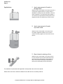
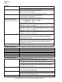
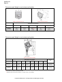
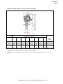
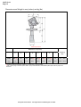
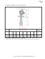
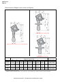
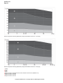
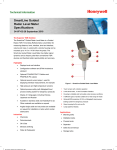
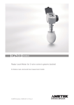
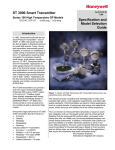
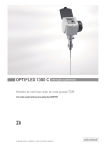
SmartLine Non-Contact Radar Level Meter 34-VF-03-19 May 2010 Technical Datasheet Specification The Universal Radar Solution The SmartLine Non-Contact Radar Level Meter (FMCW) designed for distance, level and volume measurement of liquids, pastes and slurries. It gives a more stable measurement than pulse radar and is well suited to agitated process conditions. The device can operate at very low and very high process temperatures as long as the process connection temperature limits are observed. Highlights ±3 mm / ±0.12" standard accuracy Reliable measurement in difficult process conditions Operates up to a flange temperature of 200°C (390°F) and 100 barg (1450 psig) Measuring range up to 80 m (260 ft) Long antenna versions can be extended to suit nozzle length Drop antenna for corrosive liquids (with optional PTFE/PP flange plate) or where product build-up is likely Sealed drop antenna extension option for pressurized tanks Hygienic antenna for processes where stringent hygiene standards must be obeyed PACTware and HART DTMs included as standard Optional second current output Figure 1 – SmartLine Non-Contact Radar Level Meter Direct-accessible graphic touchscreen/wizard (option) Converter rotates 360° Triple barrier gas-tight protection available for working with dangerous gases (using prestressed fused glass) 1. Optional touch screen with 4-button operation 2. 2-wire level meter 3. One converter for all applications 4. Antenna extension (for long nozzles) Industries Chemicals Food & Beverage Iron, Steel & Metals Minerals & Mining Oil & Gas Petrochemicals Pulp & Paper Water & Wastewater 5. Optional Metaglas barrier 6. Rotatable housing 7. Same housing for Ex d and Non-Ex Applications Tanks with agitators Process tanks Storage tanks Honeywell Field Solutions 512 Virginia Drive Fort Washington, PA 19034 34-VF-03-19 Page 2 Applications 1. Level measurement of liquids in storage tanks SmartLine Non-Contact Radar can measure the level of a wide range of liquid products on a large variety of installations, including LPG and LNG tanks. It does not require calibration or commissioning when installed. It can measure any liquid within the stated pressure and temperature range, and distances up to 80 m / 260 ft 2. Level measurement of liquids in process tanks SmartLine Non-Contact Radar can measure level accurately in agitated conditions, such as near to vortexes caused by agitators, and also where foam is present. 3. Open channel metering or flow SmartLine Non-Contact Radar can measure level in an open channel and convert this measurement into flow values if the characteristics of the channel are known. This solution is the high end alternative to ultrasonic and hydrostatic pressure transmitters. For installation requirements and application needs please refer to the User manual. Please refer to the User manual for details of how and where to use these products. Honeywell Field Solutions 512 Virginia Drive Fort Washington, PA 19034 34-VF-03-19 Page 3 4. Measurement of corrosive liquids with drop antenna The drop antenna option combines a relatively small radar beam for more precise measurement and a shape that avoids product build-up. If the tank contains corrosive liquids such as acids and alkaline solutions, we recommend the DN 80 / 3¨ drop antenna with the PTFE or PP flange plate option 5. Measurement of liquids in a bypass chamber The drop antenna option combines a relatively small radar beam for more precise measurement and a shape that avoids product build-up. If the tank contains corrosive liquids such as acids and alkaline solutions, we recommend the DN 80 / 3¨ drop antenna with the PTFE or PP flange plate option 6. Measurement of liquids with a hygienic antenna The Hygienic antenna option is made of materials that agree with FDA regulations. it is suitable for level measurement in processes that require hygienic equipment (such as the food, beverage and pharmaceutical industries). For installation requirements and application needs please refer to the User manual. Please refer to the User manual for details of how and where to use these products. Honeywell Field Solutions 512 Virginia Drive Fort Washington, PA 19034 34-VF-03-19 Page 4 Technical Data Measuring System Measurement principle 2-wire loop-powered level transmitter; K-band (24...26 GHz) FMCW radar Application range Level measurement of liquids, pastes and slurries Primary measured value Δf (change in frequency) between the emitted and received signal Secondary measured value Distance, level, volume and reflectivity Design The measurement system consists of a measuring sensor (antenna) and a signal converter which is only available in a compact version Integrated LCD display with sun cover (-20..+60°C / -4…+140°F); if the ambient temperature is not in these limits, the display switches off Construction Options 2nd current output FOUNDATION Fieldbus output (4-wire device with local HART communication) PROFIBUS PA output (4-wire device with local HART communication) PTFE/PP flange plate (for Drop antennas without antenna extensions only) Distance piece (for process temperature: +150...+200°C) (1) Antenna purging system (supplied with ¼ NPTF connection) Accessories Weather protection Antenna extensions of 105 mm / 4.1¨ length (Max length for Drop antenna versions: 525 mm / 20.7¨; not available for the Hygienic antenna) Max. measuring range 80 m / 260 ft Depends on the antenna option, dielectric constant of the product and installation type. Refer also to "Antenna selection". Min. tank height 0.2 m / 8¨ (1 m / 40¨ for hygienic antenna) Dead zone Antenna extension length + antenna length + 0.1 m / 4¨ (500 mm / 20¨ for hygienic antenna) Beam angle of antenna Horn DN40 / 1.5¨: 20° Horn DN50 / 2¨: 15° Horn DN80 / 3¨: 10° Horn DN100 / 4¨: 8° Drop DN80 / 3¨: 8° Hygienic DN50 / 2¨: 15° Display and user interface LCD display Display 9 lines, 160 × 160 pixels in 8-step greyscale with 4-button keypad Interface languages English, German, French, Italian, Spanish, Portuguese, Japanese, Chinese (Mandarin) and Russian Measuring accuracy Resolution 1 mm (0.04“) Repeatability ±1 mm (±0.04“) Accuracy ±3 mm (±0.12"), when distance 10 m (33 ft); ±0.03% of measured distance, when distance > 10 m (33 ft) Honeywell Field Solutions 512 Virginia Drive Fort Washington, PA 19034 34-VF-03-19 Page 5 Reference Conditions acc. to EN 60770 Temperature +20°C ±5°C / +70°F ±10°F Pressure 1013 mbara ±20 mbar / 14.69 psia ±0.29 psi Relative air humidity 60% ±15% Target Metal plate in an anechoic chamber Process conditions Ambient temperature -40…+80°C / -40…+175°F (according to the temperature limits of the gasket material. Refer to "Materials" in this table.) Ex: see supplementary operating instructions or approval certificates Storage temperature -40…+85°C (-40…+185°F) Flange temperature Horn antenna Standard: -50…+150°C / -58…+300°F Option: -50…+200°C / -58…+390°F (the process connection temperature must agree with the temperature limits of the gasket material. Refer to "Materials" in this table.) Ex: see supplementary operating instructions or approval certificates Drop antenna (PTFE) -50…+150°C / -58…+300°F (the process connection temperature must agree with the temperature limits of the gasket material. Refer to "Materials" in this table.) Ex: see supplementary operating instructions or approval certificates Drop antenna (PP) -40…+100°C / -40…+210°F (the process connection temperature must agree with the temperature limits of the gasket material. Refer to "Materials" in this table.) Ex: see supplementary operating instructions or approval certificates Hygienic antenna (PEEK): -20…+150°C / -4…+300°F (the process connection temperature must agree with the temperature limits of the gasket material. Refer to "Materials".) Ex: Pending Thermal shock resistance <40°C/s / <72°F/s Operating pressure Drop antenna (PP) -1…16 bar / -14.5…232 psig; subject to process connection used and flange temperature Drop antenna (PTFE): -1…40 barg / -14.5…580 psig; subject to process connection used and flange temperature Hygienic antenna (PEEK): -1…10 barg / -14.5…145 psig subject to process connection used and flange temperature Horn antennas: Standard: -1…40 barg / -14.5…580 psig; Option: -1…100 barg / -14.5…1450 psig; subject to process connection used and flange temperature Dielectric constant (εr) Vibration resistance 1.5 IEC 60068-2-6 and EN 50178 (10...57 Hz: 0.075 mm / 57...150 Hz:1g) Protection category IP 66/67 equivalent to NEMA type 4X (housing) and type 6P (antenna) Installation conditions Process connection size The process connection should be larger than the antenna diameter. If the process connection on the device is smaller than the antenna, either: - provide the means to adapt the device to a larger process connection on the tank (for example, a plate with a slot), or - use the same process connection, but remove the antenna from the device before installation and fit it from inside the tank. Process connection position Make sure that there are not any obstructions directly below the process connection for the device. Honeywell Field Solutions 512 Virginia Drive Fort Washington, PA 19034 34-VF-03-19 Page 6 Material Housing Standard: Aluminium Wetted parts, including antenna Process fitting Gaskets (and o-rings for the sealed antenna extension option Option: Stainless steel (1.4404 / 316 L) Standard for Horn antenna: Stainless steel (1.4404 / 316L) Option for Horn antenna: Hastelloy® C-22 (2.4602) (2) Standard for Drop antenna: PTFE; PP Hygienic antenna: PEEK - this material agrees with FDA regulations Standard for Horn and Drop antennas: Stainless steel (1.4404 / 316L) - a PP or PTFE flange plate is also available for the Drop antenna Standard for Hygienic antennas:PEEK Option: Hastelloy® C-22 (2.4602) - for Horn antennas only Hygienic antenna: BioControl®: FKM/FPM (-20…+150°C / -4…+300°F); EPDM (-20°C…+150°C / -4…+300°F) SMS, Tri-Clamp®, DIN 11851: without (3) PTFE Drop antennas: ® FKM/FPM (-40…+150°C / -40…+300°F); Kalrez 6375 (-20…+150°C / -4…+390°F); EPDM (50°C…+150°C / -58…+300°F) (4) PP Drop antennas: FKM/FPM (-40…+100°C / -40…+210°F); Kalrez® 6375 (-20…+100°C / -4…+210°F); EPDM (-40°C…+100°C / -40…+210°F) (4) Horn antennas: FKM/FPM (-40…+200°C / -40…+390°F); Kalrez® 6375 (-20…+200°C / -4…+390°F); EPDM (-50°C…+150°C / -58…+300°F) (4) Feedthrough Standard: PEI (-50...+200°C / -58...+390°F - max. range. The feedthrough temperature limits must agree with the temperature limits of the gasket material and antenna type. If the distance piece option is not attached, the maximum temperature is 150°C / 300°F.) Option: Metaglas® (-30...+200°C / -22...+390°F - max. range. The feedthrough temperature limits must agree with the temperature limits of the gasket material and antenna type. If the distance piece option is not attached, the maximum temperature is 150°C / 300°F.) (5) Weather protection (Option) Stainless steel 1.4301 (304) Process Connections Thread G 1½"; NPT 1½" Flange EN ASME JIS Hygienic Other DN40…150 in PN16, PN40, PN63 or PN100; others on request 1½¨…8¨ in 150 lb, 1½¨...6¨ in 300 lb, 1½¨...4¨ in 600 lb or 900 lb; others on request 40…100A in 10K; others on request BioControl® DN50; Tri-Clamp® 2¨; DIN 11851 DN50; SMS 51; others on request M40 connection for process connections supplied by the customer Electrical Connections Power Supply Terminals output 1 - Non-Ex / Ex i: 14…30 VDC; min./max. value for an output of 22 mA at the terminal Terminals output 1 - Ex d: 20…36 VDC; min./max. value for an output of 22 mA at the terminal Terminals output 2 - Non-Ex / Ex i / Ex d: 10…30 VDC; min./max. value for an output of 22 mA at the terminal (additional power supply needed - output only) Cable entry M20x1.5; ½" NPT G ½" (not for FM- and CSA- approved devices. Not for stainless steel housings) M25x1.5 (For stainless steel housing only) Cable gland Standard: none Options: M20x1.5 (for non-Ex and Ex -approved devices with M20x1.5 and M25x1.5 cable entries); others are available on request Cable entry capacity (terminal) 0.5…1.5 mm² Honeywell Field Solutions 512 Virginia Drive Fort Washington, PA 19034 34-VF-03-19 Page 7 Input and Output Current Output Output signal (Output 1) 4…20 mA HART® or 3.8…20.5 mA acc. to NAMUR NE 43 (6) Output signal (Output 2 - optional) 4…20 mA (no HART® signal) or 3.8…20.5 mA acc. to NAMUR NE 43 Resolution ±3 μA Typically 50 ppm/K Temperature drift Error signal PROFIBUS PA High: 22 mA; Low: 3.6 mA acc. to NAMUR NE 43 Type 4-wire (+ local HART) level transmitter; K-band FMCW radar Function blocks Protocol / Communication 7 (level, distance, level conversion, level mass, reflection, ullage conversion and distance mass) PROFIBUS PA protocol that agrees with IEC 61158-2, galvanically isolated Physical layer types Standard power signaling, bus powered, non I.S. Other features Bus interface with integrated reverse polarity protection Device power supply (24 V input) 18...30 VDC Current consumption on PROFIBUS network 20 mA Input data Level, distance, level conversion, level mass, reflection, ullage conversion or distance mass None Error current FDE Typically 0 mA (FDE =Fault Disconnection Electronic) Address range FOUNDATION Fieldbus 0...125. Default address: 126. Type 4-wire (+ local HART) level transmitter; K-band FMCW radar Function blocks 1 × Resource Block (RB), 4 × Analog Input Blocks (RB), 1 × Transducer Block (TB) Foundation Fieldbus protocol that agrees with IEC 61158-2, galvanically isolated Output data Protocol / Communication standard ITK version 5.1 Physical layer types Standard power signaling, bus powered, non I.S. Other features Bus interface with integrated reverse polarity protection Device power supply (24 V input) 18...30 VDC Current consumption on 20 mA Output data Level, distance, level conversion, level mass, reflection, ullage conversion or Input data distance mass None Error current FDE Typically 0 mA (FDE =Fault Disconnection Electronic) Link Master function Not supported Honeywell Field Solutions 512 Virginia Drive Fort Washington, PA 19034 34-VF-03-19 Page 8 Approvals CE This device fulfils the statutory requirements of the EC directives. The manufacturer certifies successful testing of the product by applying the CE mark. ATEX (approval for Hygienic antennas and fieldbus outputs pending) IECEx (approval pending) ATEX II G 1, 1/2, 2 Ex ia IIC T6...T3; ATEX II D 1, 1/2, 2 Ex iaD 20 or Ex iaD 20/21 or Ex iaD 21 IP6X T65°C...T90°C; ATEX II G 1/2, 2 Ex d [ia] IIC T6...T3; ATEX II D 1, 1/2, 2 Ex tD[iaD] A21/20 or Ex tD[iaD] A21 IP6X T65°C...T90°C; ATEX II G 3 Ex nA IIC T6…T3 Zone 0 Ex ia IIC T6…T3; Ex iaD 20 IP6X T65°C…T 90°C Zone 0/1 Ex d[ia] IIC T6…T3; Ex tD[iaD] A20/21 IP6X T65°C…T 90°C (pending) FM Dual Seal-approved (approval for hygienic antenna and fieldbus output options pending) NEC 500 XP-IS: Cl. I, Div. 1, Gr. ABCD (also applicable to these conditions: Cl. II/III, Div. 2, Gr. FG); DIP: Cl. II/III, Div. 1, Gr. EFG; IS: Cl. I/II/III, Div. 1, Gr. ABCDEFG; NI: Cl. I, Div. 2, Gr. ABCD; NEC 505 XP-IS: Cl. I, Zone 0, AEx d [ia], IIC; IS: Cl. I, Zone 0, AEx ia, IIC; NI: Cl. I, Zone 2, AEx nA [ia], IIC Temperature class: T6 Ta=60°C; T4A Ta=85°C Hazardous (Classified) Locations, indoor/outdoor Type 4X and 6P, IP66, Dual Seal CSA - Dual Seal-approved (approval for Drop antenna, hygienic antenna and fieldbus output options pending) CEC Section 18 (Zone ratings) Cl. I, Zone 1, Ex d [ia], IIC (Probe: Zone 0); Cl. I, Zone 0, Ex ia, IIC; Cl. I, Zone 2, Ex nA [ia], IIC; CEC Section 18 and Annex J (Division ratings) XP-IS, Cl. II, Div. 2, Gr. FG; Cl. III, Div. 2; IS, Cl. I, Div. 2, Gr. ABCD; Cl. II, Gr. FG; Cl. III NEPSI (approval pending) Ex dia IIC T3…T6; Ex ia IIC T3…T6 CEPEL / INMETRO (pending) Other standards and approvals Ex d[ia] IIC T3…T6; Ex ia IIC T3…T6 EMC EMC Directives 2004 / 108 / EC in conjunction with EN 61326-1 (2006). LVD Low-Voltage Directives 2006 / 95 / EC in conjunction with EN 61010-1 (2001). NAMUR NAMUR NE 21 Electromagnetic Compatibility (EMC) of Industrial Process and Laboratory Control Equipment NAMUR NE 43 Standardization of the Signal Level for the Failure Information of Digital Transmitters Construction code On request: NACE MR0175 / ISO 15156 1 the device has a distance piece if it has the flange options that follow: 6¨ in 300 lb, 3¨...4¨ in 600 lb and 1½¨...4¨ in 900 lb ® 2 Hastelloy is a registered trademark of Haynes International, Inc. ® ® 3 Tri-Clamp is a registered trademark of Ladish Co., Inc. BioControl is a registered trademark of Neumo-Ehrenberg-Group. ® 4 Kalrez is a registered trademark of DuPont Performance Elastomers L.L.C. ® 5 Metaglas is a registered trademark of Herberts Industrieglas, GMBH & Co., KG ® 6 HART is a registered trademark of the HART Communication Foundation Honeywell Field Solutions 512 Virginia Drive Fort Washington, PA 19034 34-VF-03-19 Page 9 Dimensions and Weight Note: Cable glands are delivered on demand with non-Ex, Ex i- and Ex d-approved devices. The diameter of the outer sheath of the cable must be 6…12 mm or 0.2…0.5¨. Cable glands for FM- or CSA-approved devices must be supplied by the customer. A weather protection cover is available on request with all devices. Dimensions in mm (inches) and kg (lbs) Housing front view Housing side view Dimensions mm (inches) a Housing b c d e f g 180 122 158.5 182 (1) 167 277 155 3.3 (7.1) (4.8) (6.2) (7.2) (6.7) (10.9) (6.10) (7.3) 1 if fitted with cable glands Honeywell Field Solutions 512 Virginia Drive Fort Washington, PA 19034 Weight kg (lbs) 34-VF-03-19 Page 10 Dimensions and Weight in mm (inches) and kg (lbs) Weather protection back view Weather protection left side Dimensions mm (inches) Weather protection a b c d Weight kg (lbs) 208 231.5 268 (1) 66 2.9 (8.2) (9.1) (10.6) (2.6) (6.4) 1 radius Dimensions and Weight in mm (inches) and kg (lbs) Antenna with thread connection f h i Weight kg (lbs) 359 32 126 (3) 39 5.1 (9.2) (14.1) (1.3) (4.9) (1.5) (11.2) 201 234 370 32 136 43 5.3 (7.9) (9.2) (14.5) (1.3) (5.3) (1.7) (11.6) Dimensions mm (inches) d e a b c DN40/1.5” Antenna 194 (1) 170 201 233 (7.6) (6.7) (7.9) DN50/2” Antenna 182 (1) 167 (7.2) (6.5) 1 if fitted with standard cable glands 2 1½" NPT or G process connections available 3 additional antenna extensions of Ø39 (1.5) × length 105 (4.1) are available Honeywell Field Solutions 512 Virginia Drive Fort Washington, PA 19034 34-VF-03-19 Page 11 Dimensions and Weight in mm (inches) and kg (lbs) DN40/50 long antenna Dimensions mm (inches) A b c d e f h i DN40 194 (1) 170 201 246 (3) 342 (3) 45 (3) 96 (2) 39 6.6…14.1 long (7.6) (6.7) (7.9) (9.7) (13.5) (1.8) (3.8) (1.5) (14.4…31.1) DN50 182 (1) 167 201 246 (3) 353 (3) 45 (3) 107 (2) 43 6.8…14.3 long (7.2) (6.5) (7.9) (9.7) (13.9) (1.8) (4.2) (1.7) (14.8…31.5) Weight kg (lbs) 1 if fitted with standard cable glands 2 additional antenna extensions of Ø39 (1.5) × length 105 (4.1) are available 3 with ¼ NPTF purge connection option: add 17 (0.7) to this dimension. With distance piece option: add 71 (2.8) to this dimension Honeywell Field Solutions 512 Virginia Drive Fort Washington, PA 19034 34-VF-03-19 Page 12 Dimensions and Weight in mm (inches) and kg (lbs) DN80 long antenna Dimensions mm (inches) a b c d e f h i Weight kg (lbs) DN80 182 (1) 167 201 246 (3) 463 (3) 45 (3) 217 (2) 75 11.1…18.9 long (7.2) (6.5) (7.9) (9.7) (18.2) (1.8) (8.5) (3.0) (24.4…41.5) 1 if fitted with standard cable glands 2 additional antenna extensions of Ø39 (1.5) × length 105 (4.1) are available 3 with ¼ NPTF purge connection option: add 17 (0.7) to this dimension. With distance piece option: add 71 (2.8) to this dimension Honeywell Field Solutions 512 Virginia Drive Fort Washington, PA 19034 34-VF-03-19 Page 13 Dimensions and Weight in mm (inches) and kg (lbs) DN100/4” long horn antenna Dimensions mm (inches) Weight kg (lbs) a b c d e f h i DN100 182 (1) 167 201 246 (3) 532 (3) 45 (3) 286 (2) 95 11.6…28.2 long (7.2) (6.5) (7.9) (9.7) (20.9) (1.8) (11.3) (3.7) (25.6…62.2) 1 if fitted with standard cable glands 2 additional antenna extensions of Ø39 (1.5) × length 105 (4.1) are available 3 with ¼ NPTF purge connection option: add 17 (0.7) to this dimension. With distance piece option: add 71 (2.8) to this dimension Honeywell Field Solutions 512 Virginia Drive Fort Washington, PA 19034 34-VF-03-19 Page 14 Dimensions and Weight in mm (inches) and kg (lbs) DN80/3” drop antenna, without plate DN80/3” drop antenna, with G 1½ or 1½ NPT thread conn DN80/3” drop antenna, with plate Thread Flange Flange with plate a 182 (1) b 167 c 201 (7.2) (6.5) (7.9) Dimensions mm (inches) d e f 234 399 33 (9.2) (15.7) Weight kg (lbs) h 165 (2) i 74 (1.3) (6.5) (2.9) 182 (1) 167 201 246 383 45 137 (2) 74 (7.2) (6.5) (7.9) (9.7) (15.1) (1.8) (4.5) (2.9) j - 5.7…6.1 (12.6…13.4) - 6.3…26 (13.9…57.3) 182 (1) 167 201 246 383 45 137 (2) 74 39* 6.6…26.8 (7.2) (6.5) (7.9) (9.7) (15.1) (1.8) (5.4) (2.9) (1.5) (13.9…59.1) 1 if fitted with standard cable glands 2 additional antenna extensions of Ø39 (1.5) × length 105 (4.1) are available. Do not attach more than 5 antenna extensions. Honeywell Field Solutions 512 Virginia Drive Fort Washington, PA 19034 34-VF-03-19 Page 15 Dimensions and Weight in mm (inches) and kg (lbs) 1 DN50/2¨ Hygienic antenna with DIN 11851 connection 2 DN50/2¨ Hygienic antenna with Tri-Clamp® connection 3 DN50/2¨ Hygienic antenna with Neumo BioControl® connection 4 DN50/2¨ Hygienic antenna with SMS connection Dimensions mm (inches) DIN 11851 connection Tri-Clamp® connection Neumo BioControl® connection SMS connection a b d h Weight kg (lbs) 182 (1) 167 264 8 3.8 (7.2) (6.5) (10.4) (0.3) (8.4) 182 (1) 167 264 8 3.7 (7.2) (6.5) (10.4) (0.3) (8.2) 182 (1) 167 247 25 4.0 (7.2) (6.5) (9.7) (1.0) (8.8) 182 (1) 167 264 8 3.8 (7.2) (6.5) (10.4) (0.3) (8.4) 1 if fitted with standard cable glands Honeywell Field Solutions 512 Virginia Drive Fort Washington, PA 19034 34-VF-03-19 Page 16 Antenna selection: liquid applications The graphs below show which antenna to select for the application based on: D, the measuring range, r is the dielectric constant of the product being measured and the application. 1 Distance, D [m] 2 Distance, D [ft] 3 Dielectric constant (r) range for storage/agitator applications 4 Dielectric constant (r) range for process/agitator applications 5 DN 80 or DN 100 Horn antenna in a still well 6 DN 80 or DN 100 Horn antenna with or without a still well, or DN 80 Drop antenna without a still well 7 DN40, DN 50, DN 80 or DN 100 Horn antenna with or without a still well, DN 80 Drop antenna without a still well or Hygienic antenna 34-VF-03-19 Page 17 Guidelines for maximum operating pressure Make sure that the devices are used within their operating limits. Pressure / temperature de-rating (EN 1092-1), flange and threaded connection, in °C and barg Pressure / temperature de-rating (EN 1092-1), flange and threaded connections, in °F and psig 1 p [barg] 2 T [°C] 3 p [psig] 4 T [°F] 5 Threaded connection, G (ISO 228-1) 6 Flange connection, PN100 7 Flange connection, PN63 8 Flange connection, PN40 9 Flange connection, PN16 Honeywell Field Solutions 512 Virginia Drive Fort Washington, PA 19034 34-VF-03-19 Page 18 Pressure / temperature de-rating (ASME B16.5), flange and threaded connections, in °C and barg Pressure / temperature de-rating (ASME B16.5), flange and threaded connections, in °F and psig 1 p [barg] 2 T [°C] 3 p [psig] 4 T [°F] 5 Flange connection, Class 900 and Class 1500. Threaded connection, NPT (ASME B1.20.1). 6 Flange connection, Class 600 7 Flange connection, Class 300 8 Flange connection, Class 150 Honeywell Field Solutions 512 Virginia Drive Fort Washington, PA 19034 34-VF-03-19 Page 19 This page has been intentionally left blank Honeywell Field Solutions 512 Virginia Drive Fort Washington, PA 19034 34-VF-03-19 Page 20 Ordering Information Contact your nearest Honeywell sales office, or In the U.S.: Honeywell Process Solutions Honeywell International Inc 2500 West Union Hills Drive Phoenix, AZ 85027 1-800-343-0228 In Canada: The Honeywell Centre 155 Gordon Baker Rd. North York, Ontario M2H 3N7 1-800-461-0013 In Latin America: Honeywell Inc. 480 Sawgrass Corporate Parkway, Suite 200 Sunrise, FL 33325 (954) 845-2600 In Europe and Africa: Honeywell S. A. Avenue du Bourget 1 1140 Brussels, Belgium In Eastern Europe: Honeywell Praha, s.r.o. Budejovicka 1 140 21 Prague 4, Czech Republic In the Middle East: Honeywell Middle East Ltd. Khalifa Street, Sheikh Faisal Building Abu Dhabi, U. A. E. In Asia: Honeywell Asia Pacific Inc. Honeywell Building, 17 Changi Business Park Central 1 Singapore 486073 Republic of Singapore In the Pacific: Honeywell Pty Ltd. 5 Thomas Holt Drive North Ryde NSW Australia 2113 (61 2) 9353 7000 In Japan: Honeywell K.K. 14-6 Shibaura 1-chrome Minato-ku, Tokyo, Japan 105-0023 Or, visit Honeywell on the World Wide Web at: http://www.honeywell.com/ps Specifications are subject to change without notice. Honeywell Field Solutions 512 Virginia Drive Fort Washington, PA 19034