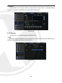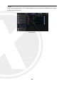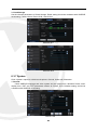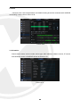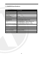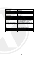
1
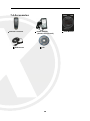
HD 1080P Professional AHD DVR 4, 8 & 16 Channel User Manual Thank you for purchasing the Xvision AHD XHRDVR. Please ensure that you read and understand this User Guide and use it before operating the Xvision XHRDVR. Please Store this User Guide in an easily accessible location. Version 1 Contents CHAPTER 1 FUNCTION DESCRIPTIONS AND FEATURES............................. 1 CHAPTER 2 OVERVIEW OF XHRDVR ............................................................... 2 2.1 FRONT PANEL ...............................................................................................................2 2.1.1 Front panel of XHRDVR with 4/8/16 channels .......................................... 2 2.2 REAR PANEL .................................................................................................................4 2.2.1 Rear panel for XHRDVR with 4/8/16 channel ........................................... 4 2.3 Remote Controller ................................................................................................ 5 CHAPTER 3 XHRDVR CONNECTION................................................................. 5 3.1 HDD INSTALLATION .......................................................................................................5 3.2 CAMERA AND MONITOR CONNECTION ..............................................................................5 3.3 POWER SUPPLY CONNECTION ..........................................................................................5 CHAPTER 4 XHRDVR BOOT UP......................................................................... 6 4.1 SYSTEM INITIALIZATION ...................................................................................................6 4.2 START-UP WIZARD .........................................................................................................6 4.3 MAIN INTERFACE ...........................................................................................................7 CHAPTER 5 XHRDVR MENU............................................................................... 8 POPUP MENU ....................................................................................................................8 5.1 MAIN MENU GUIDE ......................................................................................................9 5.2 MAIN MENU ..............................................................................................................10 5.2.1 PARAMETER.............................................................................................................10 5.2.2 Record Search ............................................................................................. 18 5.2.3 Device ............................................................................................................ 22 5.2.4 PTZ and Cloud Storage .............................................................................. 23 5.2.5 System Note: Your P2P QR code will be shown here, scan this with the XIQCMS APP for remote access to your XHRDVR. ........................................ 24 5.2.6 Advanced ...................................................................................................... 27 5.2.7 Shutdown ...................................................................................................... 28 5.3 MENU LOCK ...............................................................................................................28 5.4 SPLIT MODE...........................................................................................................28 5.5 RECORD SEARCH ..................................................................................................29 5.6 MUTE......................................................................................................................29 5.7 START SEQUENCE .................................................................................................29 CHAPTER 6 WEB APPLICATION MANAGER.................................................. 29 6.1 ACTIVEX CONTROL DOWNLOAD AND INSTALLATION .............................................................29 6.2 WEB APPLICATION MANAGER LOGIN...............................................................................30 6.3 LIVE INTERFACE ...........................................................................................................31 6.3.1 Menu Bar ...................................................................................................... 31 6.3.2 Playback ........................................................................................................ 32 6.3.3 Remote Setting ........................................................................................... 35 2 6.3.4 Network ......................................................................................................... 37 6.3.5 Alarm .............................................................................................................. 40 6.3.6 Device ............................................................................................................ 41 6.3.7 System ........................................................................................................... 43 6.3.8 Advanced ...................................................................................................... 45 6.3.9 Local Setting ................................................................................................. 48 6.3.10 Logout.......................................................................................................... 48 CHAPTER 7 APPENDIX ..................................................................................... 49 7.1 TROUBLESHOOTING ..............................................................................................49 7.2 USAGE MAINTENANCE ..........................................................................................50 7.3 XHRDVR SPECIFICATION’S............................................................................................51 7.4 ACCESSORIES ..............................................................................................................54 3 SAFETY INSTRUCTION Check the input voltage (AC100V–AC240V) to the power supply module before connecting it. Do not install the equipment in an environment with too much moisture, dust or smoke dust as this may result in fire or electric shock. In the unlikely event that the equipment should malfunction and emit an abnormal smell of smoke, please immediately stop it, shut off the power and contact your supplier. Please do not place this equipment near a heat source to avoid risk of fire. Please do not store, install and use this product in danger areas with inflammable or explosive substances. Please make sure the power is turned off when installing the product. Please ensure that you install the DVR in an area with good ventilation. Please do not use the DVR in an environment where temperatures that exceed either -20°C to +55°C. 4 Chapter 1 Function Descriptions and Features Function Brief Description Real time monitoring Supported outputs, VGA and HDMI, supports real-time monitoring by XIQCMS Windows software CMS and Smart phone XIQCMS, supports electronic amplifier, multi-screen sequence and PIP display. Recording Video compression H.264, The video quality, resolution of each channel and video frame rate are adjustable. Support many recording modes, such as start-up recording, timing recording, manual recording, alarm recording, motion detection recording, remote recording, etc. Record storage Record playback Record backup Alarm setting Network operation Mouse operation PTZ control UTC Unique touch buttons Supports high capacity 6TB single HDD with SATA port. Supports single-channel or multi-channel search and playback through the XHRDVR DVR or network. Backup records from the XHRDVR to USB flash disk, mobile HDD and disk burner; or from network to HDD. Supports alarm management of the HDD and video input and the signal input from external alarm apparatus. Supports authorized accessing of remote client to ensure the system security. Supports USB mouse operation to set system parameters conveniently and efficiently. Supports PTZ decoder communicated through RS485. It can expand two kinds of decoding protocol to communicate with PTZ and dome camera control. Support PTZ preset auto cruise function. Control your Xvision AHD cameras OSD through the XHRDVR Menu 4 new front panel quick launch buttons – Instant playback – Search – Backup – A.R.S. (Automatic Remote Setup. Table 1-1 Features: ●H.264 video compression format, Supports AHD1080P, AHD720P and 960H camera inputs. ●G.711 audio compression format; ●Full real-time six functions (preview, recording, playback, backup, network monitoring, and mobile phone monitoring); ●Supports dual-stream network transmission; ●multiple alarm modes; ●USB2.0 port, support backup, burning, software upgrading, mouse operation, etc. ●Supports infra-red remote control; ●Supports multi-language; ●Supports automatic system maintenance; 1 Chapter 2 Overview of XHRDVR 2.1 Front Panel P.S: DVR is short for Digital Video Recorder. 2.1.1 Front panel of XHRDVR with 4/8/16 channels SN Key or indicator 1 Power Indicator If the “Green” indicator is on, XHRDVR is getting power normally. 2 IR Receiver Receive IR signal from Remote Controller. 3 HDD Indicator If the “Red” indicator flashes, the hard drive is being read or written to. 4 Mute Mute switch for record search. Switch to the previous channel or next channel (8-channel XHRDVR) 5 6 7 CH- CH+ Identification Functions Change between the viewing channels. Quad On Live or Playback mode, switch to Quad display. Rewind Move to left; Rewind function; Decrease PTZ rotation speed and parameter value of graphic setting; Press and hold the key on Preview screen to switch GUI device. 2 8 Play and Pause Pause / play frame by frame manually Enter into Record Search menu and play. 9 Search Brings up the search screen. 10 Forward Select and Edit Right key; Fast forward; Increase PTZ rotation speed and parameter value of graphics. Enter into shortcut menu and select ENTER and EDIT 11 Stop/Record Stop playing or stop manual recording - Start manual record 12 Menu/ESC Enter into Main menu, exit or stop playing 13 Up key Move up 14 Down key Move down 15 PTZ: Enter into PTZ control interface 16 Instant playback Shows you the last 5 minutes recording, press multiple times to increase time. 17 Backup Instant backup, shows last 5 minutes to backup 18 A.R.S. Automatic Remote Setup – This will show you the QR code for P2P and the Network setup page. 19 USB USB port for Mouse, External HDD and DVD backup drive. 3 2.2 Rear Panel 2.2.1 Rear panel for XHRDVR with 4/8/16 channel Physical Interface Connection 1 Video input AHD 720P/1080P/Analogue 960H Camera input (BNC port) 2 Audio input Audio input RCA 3 Audio output Audio output RCA 4 LAN: Network port Connect to Router/Switch RJ45 connection 5 RS-485/Sensor/Alarm Alarm input/output and RS485 for PTZ 6 Power switch Turn on /off power supply 7 VGA VGA display output 8 HDMI HDMI display output 9 USB port USB mouse/ USB drive 10 DC Socket input Input for XHRDVR PSU 11 IR EXT IR Remote control extension SN 4 2.3 Remote Controller SN Buttons Functions 1 1-8 Channel1-8; Numerical key 2 9、0 Numerical key 3 ALL Multi-channel display 4 Menu Enter into main menu/Return 5 ▲ Move up; Volume adjustment 6 ▼ Move down; Volume adjustment ◄/ Move left/right; Decrease/increase parameter value on the control bar SEL Select/Edit; Confirm the selection 7 8 9 Fast backward 10 Enter into Record Search menu; Play 11 Fast forward 12 ● Record key 13 Pause/Sequence key 14 ■ Stop manual recording; Stop playing 15 Audio Testing 16 Mute Mute on/off Chapter 3 XHRDVR Connection 3.1 HDD Installation (1) Make sure your XHRDVR is not powered, now you can remove the screws on both sides of the XHRDVR and the rear panel. Slide the cover away from the front panel and lift off. (2) Within the XHRDVR original box you will have the SATA cables for data and a Molex cable for power, connect these to the main board. Install the HDD(s) and screw it down using the provided screws. Once secure please connect the cables to the back of the HDD. (3) You can now place the cover back on, please take care to put all screws back into the holes they came from. 3.2 Camera and Monitor Connection The XHRDVR video output signals are transmitted to VGA monitor or HDMI monitor by VGA or HDMI cable. 3.3 Power Supply Connection Please use only the supplied power adapter to connect to the XHRDVR. Please refer to table showing rear connections above. 5 Chapter 4 XHRDVR Boot up 4.1 System Initialization After connecting the power cable to the XHRDVR to wall outlet and pressing the power button, you will enter into the XHRDVR system initializing screen shown as Picture 4-1. Picture 4-1 4.2 Start-up Wizard Once booted you will be greeted with the startup wizard, if you do not want to see this wizard again after you have completed it, you may click “Don't show this window next time” to cancel. Wizard setting menu includes: Homepage, Network setup, Record Schedule and HDD. 1. Homepage and network setup. In network setup page, set the network environment of XHRDVR, as shown in Picture 4-3 Picture 4-2 Picture 4-3 6 2. Record Schedule (Picture 4-4). Set recording time and scheduled recording of the XHRDVR. Picture 4-4 3. HDD Management (Picture 4-5). HDD format and overwrite type. Picture 4-5 4.3 Main Interface Picture 4-6 Note: When internal HDD is not connected to XHRDVR, the character “H” will appear on the lower part of the main interface and accompany buzzer alarm. If you want to disable the buzzer alarm, please enter [EventAlarm] to disable HDD loss alarm, HDD space insufficiency alarm and set alarm output to “off”. 7 Chapter 5 XHRDVR Menu Popup Menu After finishing with the system wizard, click right button on the mouse, this will show the preview interface or slide the mouse to the bottom of screen to enter into Pop-up Menu. Now you can make system changes in the Main Menu, The options in the pop-up menu may be varied slightly according to different parameter settings. The options in the menu will be explained in detail in the following chapters. Picture 5-1 8 5.1 Main Menu Guide Live Display Output Private Zone Record Record Schedule Mainstream Parameter Network Sub stream Email Network DDNS RTSP FTP Main Menu Motion Alarm Alarm Record Search Record Search Event Search HDD Device PTZ Cloud Storage General General DST Users NTP System Info Log Maintenance Advanced Events Shutdown 9 5.2 Main Menu On LIVE mode, click the mouse button, or [Menu] button on the remote controller, or click [ ] icon on the toolbar to enter the main menu screen, as shown in Picture 5-2. If the system interface is locked, refer to section 4.3 to unlock by inputting password. In Main Menu mode, you can change the following settings for Parameter, Record Search, Device, System, Advanced and Shutdown. Picture 5-2 5.2.1 Parameter 1. Live Go to “Main Menu” → “Parameter” → “Display” → “Live” to enter into the interface shown as Picture 5-3. Picture 5-3 Channel: Select the channel in the drop-down list. Channel Name: Channel name, support up to 8 characters or 4 Chinese characters. Position: Set the position for the channel display Color: Click “Setup” to enter into the color setting page (Picture 5-4) Image hiding: Enable or disable the channel real-time monitoring Show Time: Enable or disable the system time display in the live interface. Copy: Copy the parameters in the channel to any other channel or all channels. Record Time: Enable or disable displaying system time in recording. Copy: Copy the setting parameter of a channel to another channel. Adjust the brightness, hue, contrast and saturation of the image in selected channel in “Live” interface. Note:To modify the parameter value in sub-menu and make it effective, click “Save” after modification and a dialog box with message “parameters have been successfully saved” will pop up. Click “OK” in the interface and click “Exit” to exit the menu. If you want to cancel the modification, click “Cancel” to exit. Picture 5-4 10 2. Output Go to “Main Menu”→ “Parameter”→ “Display”→ “Output” to enter into the interface shown as Picture 5-5. Video Output: Live Output Sequence Mode: Set sequence mode SEQ Time: Sequence time is set 5 seconds by default. User may set it as required VGA/HDMI Resolution: For VGA output or HDMI output, the optional resolution include 800×600, 1024×768, 1280×1024, 1440× 900, 1280×720, 1920×1080 Transparency: Adjust menu transparency in the range of 0--128. Picture 5-5 3. Private Zone Go to “Main Menu” → “Parameter” → “Display” → “Private Zone” to enter into the interface shown as in Picture 5-6. Privacy Zone is for setting some invisible parts in the selected channel, as shown in Picture 5-6 and Picture 5-7. 1. Select the number of the zone to be set (maximum 4 zones can be set for single channel) 2. Click “Setup” to adjust the position of the zone. 3. After finish setting, right click the mouse to return to the “Privacy Zone” page. 4. Click “Save” to save the setting. Picture 5-6 Picture 5-7 4. Record Go to “Main Menu” → “Parameter” → “Record” → “Record” to enter into the interface shown as Picture 5-8. Picture 5-8 11 Channel: Set the desired channel in the drop-down menu Record Switch: Enable/disable record Pre Record: Enable to pre-record motion detection or I/O trigger record. 5. Record Schedule Go to “Main Menu” → “Parameter” → “Record” → “Record Schedule” to enter into the Record Schedule interface to make record schedule for XHRDVR, as shown in Picture 5-9. Select the channel and the date to be set. One week’s schedule can be set. The record schedule of the current channel can be copied to any other channel or all channels. Note: 1. In the Record menu and Record Search menu, No Color stands for no record; 2. “Green” stands for normal record and “yellow” stands for motion record 3. “Red” stands for alarm record, Picture 5-9 6. Mainstream Go to “Menu” → “Parameter” → “Record” → “Mainstream” to enter into the menu interface, as shown in Picture 5-10. “Main Menu”→ “Record” → “Mainstream” Mode: Support AHD, 960H and D1. Select a resolution, save and exit main menu. Then the system will automatically restart to take effect. Resolution (960H): Support three kinds of picture quality: WD1, WHD1, and WCIF. Resolution (D1): Support three kinds of picture quality: D1, HD1, and CIF. Note: In AHD series, the supported record resolution includes 960H/720P/1080P; FPS:PAL: 1--25f/s; NTSC: 1--30f/s. Bitrate: Bitrate for local storage. User may select in the drop down list. Audio: Check the box to record channel audio during recording and there will be audio output during playing record. Un-check the box to disable recording audio and there will be no audio output during playing the record Picture 5-10 12 7. Network Go to “Main Menu” → “Parameter” → “Network” → “Network” to enter the interface shown as Picture 5-11. Select a kind of network connection (PPPOE, DHCP, and Static) and set Port, and user may remotely control the monitoring, recording, playback or backup of XHRDVR through network Picture 5-11 Take DHCP as an example. In this mode, the router automatically assigns IP address for DVR. After restarting DVR or DHCP server, the IP address obtained by DVR may be different. As a result, user shall check IP address and port number for each remote access of DVR. The operation procedure is as follows: 1. Select DHCP, click Save and refresh DVR. Input Client Port and HTTP Port (the two values must not be the same). 2. Set obtained IP address of DVR and the mapping port. Refer to section 4.2.4.2. 3. Remotely visit DVR by IP address: http://Public network IP: Web port number (such as 00080) http:// Intranet IP: Web port number (such as 00080) (Only available in the same LAN) The XHRDVR units support P2P, so there is no need for port forwarding on your router. Note: Please save after changing any settings. If there are multiple XHRDVR’s in a LAN, make sure their IP addresses are different (Refer to System), for help with Network setup please contact your System Administrator. 8. Sub stream Go to “Main Menu” → “Parameter” → “Network” → “Sub stream” to enter into the interface shown as Picture 5-12. Picture 5-12 13 Video: Sub stream switch. Select enable to preview the sub stream in the client, so as to ensure smooth playing; If Disable is selected, the client can only choose mainstream preview. FPS: FPS for network transmission. User may select value in the drop-down list. Bitrate: Bitrate for network transmission. User may select value in the drop-down list. Audio: Click √ and audio will play during network transmission. Synchronous transmission. 9. E-mail Go to “Main Menu” → “Parameter” → “Network” → “Email” to enter into the menu interface. XHRDVR alarm Email and set parameters like Email address, SSL, Email Enable, Interval and Email Schedule. Refer to Picture 5-13, for help with Email please contact your System Administrator. Picture 5-13 10. E-mail Schedule Go to “Main Menu” → “Parameter” → “Network” → “E-mail Schedule” to make Email schedule, as shown in Picture 5-14. Select the channel and the date to be set. One week’s schedule can be set. The record schedule of the current channel can be copied to any other channel or all channels. Note: 1. Green stands for Motion: Email will be sent in case of object motion; 2. Yellow stands for Alarm: Email will be sent in case of IO alarm; 3. Red stands for Exception: Email will be sent in case of exception, e.g. HDD full, HDD damage, Video loss, etc. Picture 5-14 14 11. DDNS Go to “Main Menu” → “Parameter” → “Network” → “DDNS” to enter into the menu interface. Set DDNS in any one of the above 3 network connection types after applying dynamic domain service. Remotely access XHRDVR through domain by using browser in the form of http://applied domain: mapped Web port number. When using DDNS domain name to access XHRDVR, user shall confirm that the port can be normally connected to current IP on the public network and the settings for server address/host name/user/password/setting should be consistent with XHRDVR local setting. See Picture 5-15. Picture 5-15 12. RTSP Go to “Main Menu” → “Parameter” → “Network” → “RTSP” Set User Name and Password to view video by PC software VLC (See Picture 5-16) Picture 5-16 Follow the instruction to input IP and port to preview video (See Picture 5-17) Picture 5-17 15 13. FTP Go to “Main Menu” → “Parameter” → “Network” → “FTP” Set IP, User Name and Password to view the captured pictures in the server (See Picture 5-18). Example; Enter into ftp://relay.anw.ru/and input User Name and Password to view the captured pictures (See Picture 5-19), for help with FTP please contact your System Administrator. Picture 5-18 Picture 5-19 14. Motion Go to “Main Menu” → “Parameter” → “Alarm” → “Motion” to enter into the interface shown as picture 5-20 Picture 5-20 Channel: Enable or disable Motion function. Sensitivity: Support 1-8 level, 8 is the highest level. Buzzer: When detecting object moving, buzzer makes alarms (disable, 10 seconds, 20 seconds, 40 seconds and 60 seconds). Alarm Out: Connect to the alarm switch of the alarm apparatus. Show Message: Messages will be displayed on the screen when moving object is detected and alarms are made. Send Email: When moving object is detected, send Email to the specified Email address. Full Screen: When moving object is detected, messages will be displayed in full screen. Latch Time: When moving object is detected, the alarm time can be set as 10 seconds, 20 seconds, 40 seconds and 60 seconds. Post Recording: After the alarm finishes, the duration time of the alarm recording can be set as 30 seconds, 1 minute, 2 minutes and 5 minutes. Picture 5-21 Area: Click it to enter into the interface shown as Picture 5-21 to set the motion detection area to be monitored intensively. A single channel is divided into 15×12 (PAL) or 15×10 (NTSC) configurable grids. The red grids indicate that the motion detection in the area is enabled, white semitransparent ones indicates that the motion detection in the area is disabled. After setting is completed, right click the mouse button to return and click Save to make the parameter setting effective. Record Channel: When object motion is detected, the record channel setting will be activated. 16 15. Alarm Go to “Main Menu” → “Alarm” → “Alarm” to enter into the interface shown as Picture 5-22. Alarm management and setting of the machine. Set alarms under different status in the interface. Please refer to Table 2-4. Alarm In: Set four groups of alarm input. Alarm Type: There are three kinds of status, i.e. Always ON, Always OFF, and OFF. Always ON: When the trigger is on, I/O alarm appears; Always OFF: When the trigger is off, I/O alarm appears; OFF: Do not receive I/O alarm from trigger. Buzzer Time: Set how long the buzzer will sound when motion is detected (off, 10s, 20s, 40s, 60s) Alarm out: Connect the external alarm switch. Picture 5-22 Show Message: Display the alarm messages on the screen when motion alarm is detected. Send Email: Set to send email to specified email when motion alarm is detected. Full Screen Alarm: When the motion is detected, the corresponding channel will be switched to the full screen mode. Latch time: Set how long the buzzer will sound when object move is detected by external sensor (10s, 20s, 40s, 60s) Post Recording: Set how long alarm record will last when alarm ends (30s, 1minutes, 2minutes, 5minutes). Record Channel: The record channel will be activated when the object move is detected. Copy: Allow you copy current channel parameters to any other channel (setting of record channel cannot be copied). Alarm Type Functions & Descriptions Video Loss When the XHRDVR fails to receive video signals due to some problems (camera damage, line dropout or damage, power failure), the alarm will appear. Motion Detection When camera detects object moving, alarm will be activated. Sensitivity is subject to the actual application environment test. Sensitivity is adjusted according to the sensitivity of moving object detection and parameters are modified by combining the area setting. I/O Status Communicate with alarm device through I/O port. Alarm signals sent by IR sensor or other devices will be transformed to the system recognized signal and activate relevant channel to record or control the device output. HDD Status Alarm will appear when HDD does not work due to damage, power failure, HDD auto-overwrite off and insufficient space. Table 2-1 17 5.2.2 Record Search 1. General Go to “Main Menu” → “Record Search” → “Record Search” to enter into the interface shown as Picture 5-23. Picture 5-23 Picture 5-24 Channel: Select the channel you want to search. Type: Select the type the playback record. There are two options, i.e. Normal and Alarm. Start Time/End Time: Select the specific period of time. The default setting is from 0:00 to 24:00. Playback Channel: Click a date and select corresponding channel in Playback Channel. The selected channels shall not be more than 16, as shown in Picture 5-24. Playback: Select the desired year and month and click “Search”. If there are any records, a yellow corner mark which shows the recording at specific date will appear at the down-right corner of the date sheet. Select the date checkbox and select playback channel and click Playback to enter into the interface. Playback interface: You can use the Playback Control bar to operate the Fast Forward (X2, X4, X8 and X16), Rewind (X2, X4, X8 and X16), Slow play (1/2, 1/4 and 1/8 speed), Play, Pause/Frame. You can click or drag the volume control bar to adjust volume. When playback ends, XHRDVR will remain in the playback interface, as shown in Picture 5-25. Time Axis setup, file clip and zoom in/out 1) The XHRDVR supports the processing control bar function when playing back record files (See Picture 5-25 and 5-26) Picture 5-25 Picture 5-26 Time Axis zoom: Default value is 24hours. Allow user to select 2 hours, 1 hour, 30 minutes or user-defined. 18 Detailed Operation: Fixed time axis: If you select [ ] option, that means the processing control bar cover two-hour video content. The time range refers to 1 hour before and after the middle point. 2) Record clip and backup function and playback zoom in/out function. Picture 5-27 Picture 5-28 Clip and backup: When it is under single channel playback, the [ ] icon will appear in the Play Control bar shown as Picture 5-27. Click the icon to start video clip function, click the icon again to end the function and pop up the dialog shown as Picture 5-27. Now, you may save the clipped video file. Zoom out: When it is under single channel playback, the icon will appear in the Play Control bar. Click the icon to zoom in certain area of the playback screen and right click mouse to return the Playback page (See Picture 5-28) 2. Events Go to “Main Menu” → “Record Search” → “Events” to enter into the interface shown as Picture 5-29. In this page, Search details by date, time, channel and record type. The relevant operations are as follows: Picture 5-29 : Previous page; Click the button to go to previous page when viewing events (except the first page). When viewing the first page, click this button to display the event list in the first page. : Next page; Click the button to go to next page when viewing events (except the last page). When viewing the last page, click this button to display the event list in the last page. : Jump; Input the desired record event page in the input box and click arrow button to jump to the input page. Two types of backup: Quick Backup and Backup 19 If you want to back up a record in the detailed file list, you may tick the checkbox at the left of the record (“√”means it has been selected) and click “Backup” to enter into “Select backup type” (Make sure USB disk or other portable storage device are connected), as shown in Picture 5-30. If you want to back up with USB select USB and click OK to start processing and you may see the backup progress shown as Picture 5-30. Picture 5-30 After backup finishes, message Backup Finishes will appear at down-right corner, as shown in Picture 5-31. Note: Before backup, connect devices for backup (USB flash disk or other mobile storage devices with USB interface) Picture 5-31 3. Play Backup Files 1.Copy backup files to the computer. 2. Open playback player and click “+” or “ ”. For example, if you want to choose *.264, add backup file and select a file to play, as shown in Picture 5-32 and 5-33. Picture 5-32 Picture 5-33 20 : Play: Click to play file : Pause: Click to pause. : Stop: Click to stop playback. : Next: Click to play next file. : Previous: Click to play previous file : Slow Playing: click to play at 1/2, 1/4, 1/8, 1/16 speed. : Fast Playing: click to play at 2×, 4×, 8×, 16× speed. : Open file : Full screen display : Never on top : Always on top : On top during playing : Screenshot: Save path: installation directory\Video Client\Capture : Adjust volume : Add folder or file. : Delete file in the list. : Delete all files in the list. : Expand/pack up the list. : Advanced configuration: Set the save path for the captured pictures and set the display language of player, as shown in picture 5-34. Picture 5-34 21 5.2.3 Device 1. HDD Go to “Main Menu” → “Device” → “HDD” to enter into the interface shown as Picture 5-35. When HDD is connected, the system will automatically detect if HDD is normal or not; if HDD needs to be formatted, status will be shown as “Not formatted”. Select the HDD and format the HDD. If the system detects HDD is normal state, the HDD status will be shown as “Normal”. See Picture 5-36 Picture 5-35 No.: Number of HDD connected to system. Status: Shows the current status of HDD. It will be available only when HDD is “Normal”. Free/Total Space: Remaining or total space of HDD Free Time: Remaining time for HDD recording according to currently set “Resolution”, “Encoding Rate” and “Frame Rate” of image. Auto-overwrite: When set to ENABLE, the XHRDVR will overwrite the oldest files on the hard drive if hard drive space is full. When set to DISABLE, the XHRDVR will stop recording if hard drive space is full. Overwrite time: 1 day, 3 days, 7 days, 14 days, 30 days and 90 days. It means the longest storage time of records in HDD. If the time is over, the records will be deleted. For example, if the time is set as 3 hours and the data in HDD include 12, 13, 14, 15, 16, 17, 18, 19 and 20 o’clock, then data 18, 19 and 20 will be saved and data 12, 13, 14, 15, 16 and 17 will be deleted. Format HDD: Format HDD for the first use. Picture 5-36 Note: Recording can only be performed when HDD is in “Normal” state. 22 5.2.4 PTZ and Cloud Storage 1. PTZ Go to “Main Menu” → “Device” → “PTZ” to enter into the interface shown as Picture 5-37. Select a PTZ channel and set PTZ protocol (Pelco-D, Pelco-P), Baud rate (1200, 2400, 4800, 9600), Data Bit(8, 7, 6, 5), Stop Bit (1, 2), Parity (None, Odd, Even Mark Space), Address and Cruise. Parameter setting for above channels must be the same as that of PTZ so that PTZ can be controlled. The protocol, baud rate and PTZ address must be set. Picture 5-37 2. Cloud Storage Cloud: Cloud Space (Network HDD). Upload the XHRDVR periodically captured pictures and motion detection captured pictures to Dropbox. 1) Register in Dropbox website, Address: https://www.dropbox.com/ 2) Configure network to ensure the normal operation of DVR network. 3) Configure Cloud: Enable Cloud and set the channel and interval for XHRDVR periodically captured pictures; Enable Motion Detection to get captured pictures for motion detection. 4) DriName refers to the name created in the folder of Dropbox and the name can be defined by the user, e.g. CloudDVR000. The folder is to store the XHRDVR periodically captured pictures (See Picture 5-38). 5) Click [Advanced E-mail Setup] to set the Email box. User shall input his Email. (See Picture 5-39) Picture 5-38 Picture 5-39 23 6) Click [Active Cloud] to activate Cloud and Email will receive the URL related to Cloud Input the registered user name to visit the above website and the following interface will pop up. 7) Click the icon at the upper-left to view the folder (CloudDVR000) made in the 4th step. 8) Enter the folder to view the XHRDVR captured pictures. 5.2.5 System Note: Your P2P QR code will be shown here, scan this with the XIQCMS APP for remote access to your XHRDVR. 1. General Go to “Main Menu” → “System” → “General” → “General” to enter into the interface shown as Picture 5-40 Set Date, Time, Date Format, Time Format, Language, Video Format, Menu Timeouts and Show Wizard in this page. Picture 5-40 2. DST Go to “Main Menu” → “System” → “General” → “DST” to enter into the interface shown as Picture 5-41 Enter into the interface shown as Picture 5-41 to set DST, Time Offset, Start Time and End Time. Picture 5-41 24 3. NTP Go to “Main Menu” → “System” → “General” → “NTP” to enter into the interface shown as Picture 5-42. NTP service: Enable/Disable NTP function. Server Address: Select NTP server (time.windows.com,time.nist.gov, pool.ntp.org). Time Zone: Corresponding time zones for various nations or regions. Update Time: Enable NTP function and save parameters and click Update Time to calibrate the system time. Note: When NTP function is set to “Enable”, system will calibrate the system time at every 00:07:50 and every start-up. Picture 5-42 4. Users Go to “Main Menu” → “System” → “Users” to enter into the User interface shown as Picture 5-43. Supports up to seven users, including one administrator and six users. Click [Edit] button to enter into the [User Edit] interface to input user name and password, as shown in Picture 5-43 User Name consists of 8 characters and password is composed by number 0-9 with max length of 8 numbers Set user password. Administer is authorized to set user common user’s authority, as shown in Picture 5-44 Log Search: Check all the system logs. Parameter: Set all the parameters. Maintain: Update version, recover ex-factory value, device reboot and shut down. Picture 5-43 Disk Management: Manage and control the HDD and USB drive. Remote Login: Remotely login XHRDVR. SEQ Control: Sequence live screens for all the channels. Manual Record: Manually start/stop record. Backup: Tick-select the ENABLE “√” option and select channel for backup, the user is allowed to backup the record in the selected channel. Live: Tick-select the ENABLE “√” option and select a channel and the user is allowed to view all the live images in the selected channel. Playback: Tick-select the ENABLE “√” option of Playback and the common user Picture 5-44 is allowed to playback the selected record in the channel. 25 5. User Edit Enable or disable the function or set password (See Picture 5-45) Picture 5-45 6. Info Go to “Main Menu” → “System” → “Info” to enter into the interface shown as Picture 5-46. Picture 5-46 7. Log Go to “Main Menu” → “System” → “Log”, as shown in Picture 5-47 Picture 5-47 Search log information in different period of time. Click “Backup” to save all the log information, as shown in Picture 5-47. 26 5.2.6 Advanced 1. Maintain Go to “Main Menu” → “Advanced” → “Maintain” to enter into the interface shown as Picture 5-48. Auto Reboot: Enable the auto maintenance function to reboot system regularly at every day/week/month. When Auto Reboot is enabled, the XHRDVR should be in the main interface and no user operation. Update: Click Update to enter the Device interface and select the updating file in USB to execute. Picture 5-48 Load Default: If [Load Default] is selected, you can initialize the system to the ex-factory default. Click “Load Default” and select items to be restored Load Settings: Load parameters on the removable storage device to the XHRDVR. Save Settings: Save the set parameters of user’s XHRDVR to the removable storage device. Note: Do not take out the USB memory or cut off the power during upgrading. When the update is done, system will be automatically restart. After about 5 minutes, the upgrading will be finished. It is recommended to load ex-factory default after upgrading. The auto maintain function can be effective only when XHRDVR returns back to Preview mode with no any operation within the set auto maintain time. 2. Events Go to “Main Menu” → “Advance” → “Events” to enter into the interface shown as Picture 5-49. Picture 5-49 27 Event Type: Supports three abnormal types: Disk Full, Disk Error and Video Loss. Enable: Active alarms for abnormal situations. Alarm Out: Enable or disable alarms Latch Time: How long the buzzer will sound when external sensor alarm is detected (10s, 20s, 40s, and 60s). Show Message: Set show message on the screen when sensor alarm is detected. Buzzer: How long the buzzer will sound (10s, 20s, 40s, and 60s). Send Email: Select to send Email to specified Email address when abnormal events appear. 5.2.7 Shutdown Go to “Main Menu” → “Shutdown” to enter into the interface shown as Picture 5-50. Picture 5-50 5.3 Menu Lock In consideration of system safety, click the icon on the toolbar when the end user leaves away from the XHRDVR and the system interface will be locked. User has to input Device ID, User Name and Password on the login interface to unlock (Default: User Name: admin, Password: blank). The login interface is as shown in Picture 5-51. Picture 5-51 Note: Administrator has all authorization of menu operation and users have limitations for authorization and have to get authorization from administrator. 5.4 Split Mode There are many display modes in video channel, including single channel display, SEQ display and split mode. 28 5.5 Record Search Click icon on the toolbar to enter into the Record Search interface to search and playback. Refer to former section for specific operating method. 5.6 Mute Click icon on the toolbar or Mute button on the panel or remote controller to control the mute of NVR. 5.7 Start Sequence After set channel sequence time, click Start Sequence icon sequence. on the toolbar to start Chapter 6 Web Application Manager 6.1 ActiveX control download and installation Open your web browser and input the IP address of the XHRDVR, such as: http://192.168.1.168 . Your PC will download and install “ActiveX” plug-in automatically. If your computer system is Windows Vista or Windows 7/8, you may need to setup the user authority for remote control, or you may not be unable to backup or record. Vista System: Start → Setup → Control Panel. Set user authority in control panel (as shown in picture below). Remove the Tick “√” in front of the option “Use UAC to help protect your computer” and confirm OK. WIN7: WIN7-1 WIN7-2 29 Note: If the ActiveX control is not downloaded successfully, please check if your browser’s safety level or firewall setting is set too high. Please open IE browser → [Menu Bar]Tools → Internet options → Security → Internet → Custom Level → Enable the options (Refer to the Picture 6-1-1 and Picture 6-1-2). If the web application runs for the first time, please wait for about one minute to finish downloading. If you want to use the undated ActiveX control at a computer which you have already logged in before, please delete the original control and click [Start → Run] and then input the command characters: “regsvr32/u HiDvrOcx.ocx”. Press OK. When you log in at the next time, new ActiveX control will be automatically downloaded. Please wait. Picture 6-1-1 Picture 6-1-2 6.2 Web Application Manager Login After ActiveX controls installation, please input user name and password, select Main Stream or Sub Stream (In general, select main stream for intranet and sub stream for outer net), and input web port number and select language in the interface (See picture 6-2). There is an option for opening all channel preview, select it to open all live pictures. Press Login to log in client and remotely visit XHRDVR. The default password is blank and administer is authorized to modify the password. Set password as per introductions of user management in system setting. Picture 6-2 30 After you have logged in, you will see the real-time monitoring interface and connect video automatically, as shown in Picture 6-2. 6.3 Live Interface Log in and enter into the live interface, as shown in Picture 6-3. Picture 6-3 6.3.1 Menu Bar Menu Bar: Live, Replay, Configuration, Local Setting and Logout. 1. Live Display Log in the Web Application Manager, system will be defaulted to enter into <Live> interface shown as Picture 6-3. You can click [Play] button to Open/close live images, on-spot record, capture, and many live display modes. Buttons on a single live interface: : Volume switch : Record switch: the remote record switch of client. Record will be automatically saved to a specified position on PC after the function is enabled. : Snapshot: Capture the selected live image and save it to a specified location on the PC. The image is saved as *.bmp format. : Open or close the images on live window. Or click the right key of mouse on each <Live> window to pop up channel operation menu as shown in Picture 6-4 Picture 6-4 Show bit rate: Tick Show Bit rate to show bit rate in current window. : Switch display mode in channel window : Open all the live channels. 31 : Close all the live channels : Display previous group of channels : Display next group of channels : Click to maximize the current window to full screen. Right click to pop up menu option and select Exit Full Screen. 2. Video Control Picture 6-5 : Adjust the chromaticity of video : Adjust the brightness of video : Adjust the contrast of video : Adjust the saturation of video 6.3.2 Playback Click to enter into Playback interface to remotely view the records on the DVR HDD, as shown in Picture 6-6. Picture 6-6 32 It supports 1 to 4 channel record playback. 1. Record Search Record playback procedure Firstly, select the date you want to check and tick 1 to 4 channels. Any record files in current channel at current date will be displayed in the status bar of the interface. (See Picture 6-7) Picture 6-7 Secondly, select record type (Normal record, Alarm record and All) and channels, and then click “ ”, and time axis panel will display specific time quantum, as shown in Picture 6-8. On the time axis, red part stands for alarm record, yellow stands for normal record and original part stands for no record during this period. Picture 6-8 Before playback, choose to enable playback 4 channels synchronously. If you tick-select “ ”, that means the selected channel will playback synchronously; otherwise, you could separately control the channels playback. Thirdly, start playback Click to start record playback. When mouse curse is moving on the time axis, the time point of current position will be displayed on the time axis screen. Click to locate the record. Click the 33 icon or to zoom in/out the time bar display ratio, as shown in Picture 6-8. 2. Playback Control Playback control bar, as shown in picture 6-9. Picture 6-9 Detailed brief description is shown as below list Key Description Key Description Play Enable the volume switch Pause Volume adjustment bar Stop Slow playing 1/2,1/4, 1/8, Fast playing 1/2/4/8 By frame Stop playing all the files Record Clip Single channel mode Snap Quad mode Download Full Screen Open all the playback channels Stop playing all the playback Table 6-1 Record file clip After opening playback, click icon to clip the selected file; and click again to stop the clip function. Then playback clip is successfully done. Record clip file will be saved as *.264 format. Snapshot function Move the mouse curse to the channel you want to capture, and click [ ] icon to capture the live images remotely. After capturing the images successfully, a path prompt box will be popped up, as shown in Picture 6-10. Picture 6-10 The captured file will be saved as .bmp format. 34 Record file download Click download icon “ ” on the control bar to display all the matched record file according to the search conditions of channels, as shown in picture 6-11. Picture 6-11 Tick-select the record file you want to download and click [Start download] .System will download the record file in sequence and save to local PC. The downloading file will be displayed in percentage form. After downloading finishes, “Complete” will be displayed on the status bar. 6.3.3 Remote Setting Click Remote Setting to enter into the interface shown as Picture 6-12, including Display, Record, Network, Alarm, Device, System and Advance. Picture 6-12 35 1. Display Unfold [Display] option to find its sub-options: Live and Privacy zone. 1) Live: You may change channel name, position, channel preview and relevant parameters. If show time is set as <disable>, current XHRDVR system time will not appear on the screen on live mode. (See Picture 6-13) Picture 6-13 2) Privacy Zone: Each channel can set 4 privacy zones, as shown in Picture 6-14. The relevant parameters should be consistent with XHRDVR local setting. Select zones to be deleted and click “Delete” and click “Save” at up-right corner. Picture 6-14 2. Record Click <Record> option to unfold its sub-options: Record parameter and Schedule. 1) Record Parameters. The parameters should be consistent with XHRDVR local setting, as shown in Picture 6-15. Picture 6-15 36 2) Record Schedule. The parameters should be consistent with XHRDVR local setting, as shown in Picture 6-16. Picture 6-16 Green stands for Normal record; Yellow stands for Motion detection; Red stands for I/O trigger record. 3) Mainstream: User may set Mainstream, as shown in Picture 6-17. The relevant parameters should be consistent with XHRDVR local setting. Picture 6-17 6.3.4 Network Unfold <Network> to show its sub-options: Network, Email, and DDNS configuration, as shown in Picture 6-18. 1. LAN setting XHRDVR supports Static/DHCP/PPPOE modes. System default network type is <Static>. User can set parameters as required. After the network parameters are modified successfully, XHRDVR will automatically restart to make the setting effective. Picture 6-18 37 2. Sub stream Set Mainstream, as shown in Picture 6-19. The relevant parameters should be consistent with XHRDVR local setting. Picture 6-19 3. Email Email: Set XHRDVR alarm Email configuration parameters, including Email address, SSL, Email Enable, Interval and Email Schedule, etc. Detailed parameters should be consistent with XHRDVR local setting. Refer to Picture 6-20. Picture 6-20 38 4. DDNS DDNS: After user applies for DDNS service, you could enable <DDNS> function under any one network type mode (Static, DHCP and PPPoe). You may remotely visit the NVR through domain name (http://domain name: Web port Number.). When visiting XHRDVR by using DDNS, user should make sure port and current IP can be normally connected in public network. Details settings, including server address, host, user, and password, should be consistent with NVR local setting. Please refer to Picture 6-21. Picture 6-21 5. RTSP Refer to Picture 6-22. The relevant parameters should be consistent with XHRDVR local setting. Picture 6-22 39 6. FTP Refer to Picture 6-23. The relevant parameters should be consistent with XHRDVR local setting. Picture 6-23 6.3.5 Alarm Alarm setting includes Motion Detection and I/O Alarm Parameters. 1. Motion Detection Configure Sensitivity, Alarm out, Alarm Record and Alarm Capture, etc. Detailed setting should be consistent with XHRDVR local setting (See Picture 6-24). Picture 6-24 40 2. I/O Alarm Set parameters for I/O Alarm, Alarm Out, Alarm Record, Send Email, etc. Detailed setting should be consistent with XHRDVR local setting (See Picture 6-25). Picture 6-25 6.3.6 Device Click <Device> to unfold its sub-options: HDD and PTZ 1. HDD Check HDD status of XHRDVR and overwritten time. Detail setting should be consistent with XHRDVR local setting. Please refer to Picture 6-26. Picture 6-26 41 2. PTZ Set the relevant parameters of PTZ. Detail setting should be consistent with XHRDVR local setting. Please refer to Picture 6-27. Picture 6-27 42 3. Cloud Storage Set the relevant parameters of Cloud Storage. Detail setting should be consistent with XHRDVR local setting. Please refer to Picture 6-28-1 and 6-28-2. Picture 6-28-1 Picture 6-28-2 6.3.7 System Click <System> option to unfold its sub-options: General, Users and Information. 1. General Check XHRDVR language and video system and set system time, date/time format, menu display time, DST and NTP parameters shown as Picture 6-29. Detailed setting should be consistent with XHRDVR local setting. Picture 6-29 43 2. Users Configure user name and password and detailed setting should be consistent with XHRDVR local setting. Please refer to Picture 6-30. Picture 6-30 3. Information Search device name, device number, device type, MAC address, software version, IE version and hardware version of XHRDVR shown as Picture 6-31. Picture 6-31 44 6.3.8 Advanced Click Advance to unfold its sub-options: Firmware Update, Load default, Events and Maintain. 1. Firmware Update Remotely update XHRDVR system, as shown in Picture 6-32. Picture 6-32 Updating procedure: Firstly, select the update file path. The file format is .sw. Please refer to Picture 6-33. Picture 6-33 Secondly, click “Start” to start updating. The updating progress can be seen on the screen, 2. Load Default Remotely restore default parameters of XHRDVR, with same setting method as that of XHRDVR, shown as Picture 6-34. Picture 6-34 45 3. Events Configure Event Type, Buzzer, Send Email, Show Message and other parameters shown as Picture 6-35. Detailed setting should be consistent with XHRDVR local setting. Picture 6-35 4. Maintain Remotely set auto maintain time for XHRDVR shown as Picture 6-36. Detailed setting should be consistent with XHRDVR local setting. Picture 6-36 5. PEA, Perimeter and Trip Line setting Perimeter: Refers to the prohibited area with any shape set by user in the field of view. In the area, the appearance and entry of the specified type of target will be detected. The specified area and type of target can be set in the client. Trip line: It is also called Guard Line, set by user to mark prohibited direction in the field of view. When the specified type of target crosses the line and move in the same direction as the prohibited direction, it will alarm. Detailed setting should be consistent with XHRDVR local setting. Refer to Picture 6-37. Picture 6-37 46 6. AVD Exception Detection Totally 8 kinds of detection items: Brightness detection, Definition, Noise, Freeze, Signal loss, Scene change, artificial disturbance, PTZ lose control. Detailed setting should be consistent with XHRDVR local setting. Refer to Picture 6-38. Picture 6-38 7. OSC Exception Detection OSC includes two functions, i.e. legacy detection and lost detection. OSC can set up to 4 rules in a channel and each rule can be set as either legacy or lost. It can set up to 4 monitoring areas for each rule, so it can set up to 16 detection areas for each channel. Detailed setting should be consistent with XHRDVR local setting. Refer to Picture 6-39. Picture 6-39 47 6.3.9 Local Setting Set Record Path (save Live record and Playback clip file), Download Path for remote file, Snapshot Path for captured pictures, Interval for switching record files (Packaging time), and File type (H264 and AVI) shown as Picture 6-40. Picture 6-40 6.3.10 Logout Click to log out and return to the login interface. 48 Chapter 7 Appendix 7.1 Troubleshooting 1. Q: What is the default user name and password for the XHRDVR A: (Default: User Name: admin, Password: blank). 2. Q: What can I do if the system does not detect the HDD? A: Check if the power supply system is properly connected and data cord and power cables are securely connected. Check if your HDD is supported by referring to your place of purchase. 3. Q: I have changed the password but forgot the new password, how can I access the system? A: If you forget system password, please contact your place of purchase or the Xvision Technical team. We strongly suggest to set a password that is easy to be remembered and relatively safe. 4. Q: Abnormal video signal or even no video signal by connecting the XHRDVR and camera together. Power supply for both devices is OK. What is wrong? A: Check HDMI/VGA cable at XHRDVR side to see if the cable is firmly connected and if it is worn out and needs to be replaced, or to check if NTSC or PAL is selected consistently. 5. Q: How to prevent XHRDVR from being influenced by heat? A: The XHRDVR needs to dissipate heat while it is running. Please place the XHRDVR in a place with good air circulation and away from heat sources to ensure stability and life of the XHRDVR 6. Q: The remote control of the XHRDVR doesn’t work, the monitor screen is OK and panel keys are functional. Why? A: Operate again by aiming the remote controller at the IR receiver on the front panel. If it still doesn’t work, please check if the batteries in the remote controller are dying. 6. Q: I want to take out HDD from my PC and install it in XHRDVR. Can it work? A: Please check with your place of purchase that the HDD you wish to put in your XHRDVR is compatible, also once you add a new HDD it will need to be formatted, You will lose all stored information on the HDD. 7. Q: Can I playback while recording? A: Yes. The system supports the function of playing while recording. 8. Q: Can I clear some records on HDD of XHRDVR? A: In consideration of the file security, you may not clear part records. If you want to remove all the records, you can format HDD. 9. Q: Why can’t I log in XHRDVR client? A: Please check if the network connection settings are correct and RJ45/CAT 5/6 port is with connected well. And check if your account and password are correctly input. 10. Q: Why can’t I find any records during playback? 49 A: Please check if the data line connection for HDD is OK and system time is properly adjusted. Try a few times and restart. If it still doesn’t work, check if the HDD is functioning correctly. 11. Q: Why XHRDVR cannot control PTZ? A: Please check if: 1. Check the PTZ connection and power supply. 2. Protocol of PTZ decoder does not match that of XHRDVR. 3. Address of PTZ decoder does not match that of XHRDVR. 4. If many decoders are connected, the farthest side of AB line of PTZ decoder should be added 120Ω resistance to realize reflection suppression and impedance matching. Otherwise, PTZ control will be unstable. 12. Q: Why doesn’t dynamic detection work? A: Please check if the motion detection time and motion detection regional setting are correct and if the sensitivity is set too low. 13. Q: Why doesn’t alarm work? A: Please check if the alarm setting, alarm connection and alarm input signals are correct. 14. Q: Why does buzzer keep alarming? A: Please check the alarm setting, check if motion detection function is enabled and object motion is detected all the time and if I/O alarm is set as Always Off. Besides, refer to corresponding HDD alarm setting. If you have no HDD present the alarm will sound. 15. Q: Why can’t I stop recording by pressing “STOP” button or click “Stop Recording” in context menu? A: Pressing Stop or Stop Recording can only stop manual record, if you want to stop Scheduled recording in certain time quantum, please change the setting to No Record. To stop Startup recording, please change record mode to scheduled recording or manual recording. Then you may stop recording by the prescribed methods. Another way of stopping recording is to set channel as off status in record setting. 7.2 Usage Maintenance 1. To shut down XHRDVR, please firstly shut down the system and then turn off the power. Do not turn off the power directly or the HDD data will be lost or damaged. 2. Please keep XHRDVR away from heat sources. 3. Clean the internal dust regularly. Make sure the XHRDVR has good ventilation this will ensure good heat dissipation. 4. Please check the HDD cable and data cable regularly to see if they are ageing. 50 7.3 XHRDVR Specification’s Model Camera Inputs Audio Inputs Monitor Outputs XHR1080D4 4CH inputs 4CH inputs VGA and HDMI output/1 RCA for audio Spot Output NO Backup Method Controls Recording Compression Recording Modes USB, IE mouse, remote control, front panel H.264 Continuous/Manual/Motion detect Recording Rate/Resolution Maximum Recording Capacity Network / Email Alerts RS485 Control UTC Alarm Inputs/Outputs Dimensions Weight PAL:25fps(each ch) / NTSC: 30fps(each ch) PAL:1920*1080P or1280*720P or 960H NTSC:1920*1080P or1280*720P or 960H 6TB YES YES Yes for Xvision AHD cameras 4 Inputs /1 Output 300X227X53mm 1.4KGS 51 Model Camera Inputs Audio Inputs Monitor Outputs Spot Output XHR1080D8 8CH inputs 8CH inputs VGA and HDMI output/1 RCA for audio NO Backup Method Controls Recording Compression USB, IE mouse, remote control, front panel H.264 Recording Modes Continuous/Manual/Motion detect Recording Rate/Resolution Maximum Recording Capacity Network / Email Alerts RS485 Control UTC Alarm Inputs/Outputs Dimensions Weight PAL:25fps(each ch) / NTSC: 30fps(each ch) PAL:1920*1080P or1280*720P or 960H NTSC:1920*1080P or1280*720P or 960H 6TB YES YES Yes for Xvision AHD cameras 8 Inputs /1 Output 300X227X53mm 1.4KGS 52 Model Camera Inputs Audio Inputs Monitor Outputs Spot Output XHR1080D16 16CH inputs 16CH inputs VGA and HDMI output/1 RCA for audio NO Backup Method Controls Recording Compression Recording Modes USB, IE mouse, remote control, front panel H.264 Continuous/Manual/Motion detect 15fps(each ch) PAL:1920*1080P NTSC:1920*1080P PAL:25fps(each ch) / NTSC: 30fps(each ch) Real time at 720P, 960H 12TB YES YES Yes for Xvision AHD cameras 16 Inputs /1 Output 380x340x50mm 3.2KGS Recording Rate/Resolution Maximum Recording Capacity Network / Email Alerts RS485 Control UTC Alarm Inputs/Outputs Dimensions Weight 53 7.4 Accessories Remote Controller USB mouse Power Adapter (Good in kind prevail) CD 54 User Manual Manufactured exclusively for: www.xvision.com TECHNICAL SUPPORT For technical support, please contact your local distributor. Alternatively, call 0871 222 1430 LIMITED WARRANTY This product is supplied with a 12 month warranty. The warranty excludes products that have been misused (including accidental damage) and damage caused by normal wear and tear. In the unlikely event that you encounter a problem with this product, it should be returned to the place of purchase. Xvision UK, Unit 2 Valley Point, Beddington Farm Road, Croydon, Surrey CR0 4WP www.xvision.com