1
YASKAWA
Machine Controller MP900 Series
New Ladder Editor
PROGRAMMING MANUAL
YASKAWA
MANUAL NO. SIEZ-C887-13.1
Copyright © 2001 YASKAWA ELECTRIC CORPORATION
All rights reserved. No part of this publication may be reproduced, stored in a retrieval system,
or transmitted, in any form, or by any means, mechanical, electronic, photocopying, recording,
or otherwise, without the prior written permission of Yaskawa. No patent liability is assumed
with respect to the use of the information contained herein. Moreover, because Yaskawa is constantly striving to improve its high-quality products, the information contained in this manual is
subject to change without notice. Every precaution has been taken in the preparation of this
manual. Nevertheless, Yaskawa assumes no responsibility for errors or omissions. Neither is
any liability assumed for damages resulting from the use of the information contained in this
publication.
About This Manual
This manual describes the programming instructons of the New Ladder Editor, a
programming software application that aids in the design and maintenance of
MP900-series Machine Controllers.
This manual is written for readers with a working knowledge of Microsoft Windows
95/NT. Refer to Windows documentation provided with your computer for information on basic operations, such as opening and closing windows and mouse operations.
Intended Audience
This manual is intended for the following users.
• Those responsible for designing the MP900 System
• Those responsible for writing MP900 motion programs
• Those responsible for writing MP900 ladder logic programs
Description of Technical Terms
In this manual, the terms are defined as follows:
• PLC = Machine Controller
• CP-717 = CP-717 Engineering Tool
Read this manual carefully to ensure the proper use of the New Ladder Editor. Also,
keep this manual in a safe place so that it can be referred to whenever necessary.
About The Software
Precautions
• This software is to be installed on one and only one computer. You must purchase
another copy of the software to install it on another computer.
• This software is not to be copied for any reason other than when installing it on the computer.
• Store the floppy disks containing the software in a safe place.
• This software is not to be decompiled, disassembled, or reverse engineered.
• This software is not to be given to, rent to, exchanged with, or otherwise released to a
third party without the prior permission of Yaskawa Corporation.
Trademarks
• Windows and Windows 95 are registered trademarks of Microsoft Corporation.
• Pentium is a registered trademark of Intel Corporation.
• Ethernet is a registered trademark of Xerox Corporation.
iii
Visual Aids
The following aids are used to indicate certain types of information for easier reference.
IMPORTANT
Indicates important information that should be memorized. Also indicates low-level
precautions that, if not heeded, may cause an alarm to sound but will not result in
the device being damaged.
EXAMPLE
INFO
Indicates application examples.
Indicates supplemental information.
iv
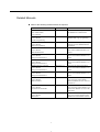
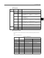
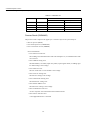
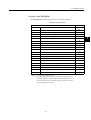
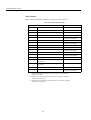
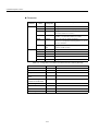
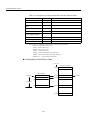
Related Manuals
Refer to the following related manuals as required.
Manual Name
Manual Number
Contents
MP900 Series Machine Controller
New Ladder Editor
User’s Manual
SIEZ-C887-13.2
Describes the operating methods of
the MP900 New Ladder Editor.
MP900 Series Machine Controller
User's Manual:
Ladder Programming
SIEZ-C887-1.2
Describes the instructions used in
MP900 ladder logic programming.
MP900 Series Machine Controller
User's Manual:
Motion Programming
SIEZ-C887-1.3
Describes the motion programming
language used for MP900 Machine
Controllers.
MP900 Series Machine Controller
User's Manual:
MECHATROLINK
SIEZ-C887-5.1
Describes MECHATROLINK Modules used for MP900 Machine Controllers.
MP910 Machine Controller
User's Manual:
Design and Maintenance
SIEZ-C887-3.1
Describes the design and maintenance for the MP910 Machine Controller.
MP920 Machine Controller
User's Manual:
Design and Maintenance
SIEZ-C887-2.1
Describes the design and maintenance for the MP920 Machine Controller.
MP930 Machine Controller
User's Manual:
Design and Maintenance
SIEZ-C887-1.1
Describes the design and maintenance for the MP930 Machine Controller.
MP940 Machine Controller
User's Manual:
Design and Maintenance
SIEZ-C887-4.1
Describes the design and maintenance for the MP940 Machine Controller.
MP920 Machine Controller
User's Manual:
Motion Module
SIEZ-C887-2.5
Describes the functions, specifications, and usage of the MP920
Motion Modules (SVA-01, SVB-01,
and PO-01).
MP920 Machine Controller
User's Manual:
Communications Module
SIEZ-C887-2.6
Describes the functions, specifications, and usage of the MP920 Communications Modules (217IF, 215IF,
and 218IF).
MP920 Machine Controller
User's Manual:
DeviceNet
SIEZ-C887-5.2
Describes the functions, specifications, and operating methods of the
MP920 DeviceNet Module (260IF).
v
CONTENTS
About This Manual- - - - - - - - - - - - - - - - - - - - - - - - - - - - - - - - - - - - - - iii
About The Software - - - - - - - - - - - - - - - - - - - - - - - - - - - - - - - - - - - - - iii
Visual Aids - - - - - - - - - - - - - - - - - - - - - - - - - - - - - - - - - - - - - - - - - - - iv
Related Manuals - - - - - - - - - - - - - - - - - - - - - - - - - - - - - - - - - - - - - - - -v
1 LADDER PROGRAM INSTRUCTIONS
1.1 Relay Circuit Instructions - - - - - - - - - - - - - - - - - - - - - - - - - 1-4
1.1.1 N.O. Contact Instruction (NOC) - - - - - - - - - - - - - - - - - - - - - - - - - - - - 1-4
1.1.2 N.C. Contact Instruction (NCC) - - - - - - - - - - - - - - - - - - - - - - - - - - - - 1-5
1.1.3 10-MS ON-DELAY TIMER Instruction (TON [10ms]) - - - - - - - - - - - - - 1-6
1.1.4 10-MS OFF-DELAY TIMER Instruction (TOFF [10ms]) - - - - - - - - - - - 1-7
1.1.5 1-S ON-DELAY TIMER Instruction (TON [1s])- - - - - - - - - - - - - - - - - - 1-8
1.1.6 1-S OFF-DELAY TIMER Instruction (TOFF [1s]) - - - - - - - - - - - - - - - 1-10
1.1.7 RISING PULSE Instruction (ON-PLS) - - - - - - - - - - - - - - - - - - - - - - 1-11
1.1.8 FALLING PULSE Instruction (OFF-PLS) - - - - - - - - - - - - - - - - - - - - 1-13
1.1.9 COIL Instruction (COIL) - - - - - - - - - - - - - - - - - - - - - - - - - - - - - - - - 1-14
1.1.10 SET COIL Instruction (S-COIL)- - - - - - - - - - - - - - - - - - - - - - - - - - 1-15
1.1.11 RESET COIL Instruction (R-COIL) - - - - - - - - - - - - - - - - - - - - - - - - 1-17
1.2 Numeric Operation Instructions - - - - - - - - - - - - - - - - - - - - 1-19
1.2.1 STORE Instruction (STORE)- - - - - - - - - - - - - - - - - - - - - - - - - - - - 1.2.2 ADDITION Instruction (ADD)- - - - - - - - - - - - - - - - - - - - - - - - - - - - 1.2.3 EXTENDED ADDITION Instruction (ADDX) - - - - - - - - - - - - - - - - - 1.2.4 SUBTRACTION Instruction (SUB) - - - - - - - - - - - - - - - - - - - - - - - - 1.2.5 EXTENDED SUBTRACTION Instruction (SUBX) - - - - - - - - - - - - - 1.2.6 MULTIPLICATION Instruction (MUL) - - - - - - - - - - - - - - - - - - - - - - 1.2.7 DIVISION Instruction (DIV) - - - - - - - - - - - - - - - - - - - - - - - - - - - - 1.2.8 MOD Instruction (MOD) - - - - - - - - - - - - - - - - - - - - - - - - - - - - - - - 1.2.9 REM Instruction (REM)- - - - - - - - - - - - - - - - - - - - - - - - - - - - - - - - 1.2.10 INC Instruction (INC) - - - - - - - - - - - - - - - - - - - - - - - - - - - - - - - - 1.2.11 DEC Instruction (DEC) - - - - - - - - - - - - - - - - - - - - - - - - - - - - - - - 1.2.12 ADD TIME Instruction (TMADD) - - - - - - - - - - - - - - - - - - - - - - - - 1.2.13 SUBTRACT TIME Instruction (TMSUB) - - - - - - - - - - - - - - - - - - - 1.2.14 SPEND TIME Instruction (SPEND) - - - - - - - - - - - - - - - - - - - - - - 1.2.15 SIGN INVERSION Instruction (INV) - - - - - - - - - - - - - - - - - - - - - - 1.2.16 1’S COMPLEMENT Instruction (COM) - - - - - - - - - - - - - - - - - - - - 1.2.17 ABSOLUTE VALUE CONVERSION Instruction (ABS) - - - - - - - - - 1.2.18 BINARY CONVERSION Instruction (BIN)- - - - - - - - - - - - - - - - - - 1.2.19 BCD CONVERSION Instruction (BCD)- - - - - - - - - - - - - - - - - - - - 1.2.20 PARITY CONVERSION Instruction (PARITY) - - - - - - - - - - - - - - - 1.2.21 ASCII CONVERSION Instruction (ASCII) - - - - - - - - - - - - - - - - - - 1.2.22 ASCII CONVERSION 2 Instruction (BINASC) - - - - - - - - - - - - - - - 1.2.23 ASCII CONVERSION 3 Instruction (ASCBIN) - - - - - - - - - - - - - - - -
vi
1-19
1-21
1-23
1-24
1-27
1-28
1-31
1-33
1-34
1-35
1-36
1-38
1-39
1-41
1-43
1-44
1-45
1-46
1-48
1-50
1-51
1-52
1-53
1.3 Logical Operation/Comparison Instructions - - - - - - - - - - - - 1-55
1.3.1 AND Instruction (AND) - - - - - - - - - - - - - - - - - - - - - - - - - - - - - - - - - 1-55
1.3.2 OR Instruction (OR) - - - - - - - - - - - - - - - - - - - - - - - - - - - - - - - - - - - 1-56
1.3.3 XOR Instruction (XOR) - - - - - - - - - - - - - - - - - - - - - - - - - - - - - - - - - 1-57
1.3.4 Comparison Instruction (<) - - - - - - - - - - - - - - - - - - - - - - - - - - - - - - 1-59
1.3.5 Comparison Instruction (<=) - - - - - - - - - - - - - - - - - - - - - - - - - - - - - 1-60
1.3.6 Comparison Instruction (=) - - - - - - - - - - - - - - - - - - - - - - - - - - - - - - 1-61
1.3.7 Comparison Instruction (!=) - - - - - - - - - - - - - - - - - - - - - - - - - - - - - - 1-62
1.3.8 Comparison Instruction (>=) - - - - - - - - - - - - - - - - - - - - - - - - - - - - - 1-63
1.3.9 Comparison Instruction (>) - - - - - - - - - - - - - - - - - - - - - - - - - - - - - - 1-64
1.3.10 RANGE CHECK Instruction (RCHK)- - - - - - - - - - - - - - - - - - - - - - - 1-65
1.4 Program Control Instructions - - - - - - - - - - - - - - - - - - - - - - 1-68
1.4.1 SUB-DRAWING CALL Instruction (SEE)- - - - - - - - - - - - - - - - - - - - - 1-68
1.4.2 MOTION PROGRAM CALL Instruction (MSEE)- - - - - - - - - - - - - - - - 1-69
1.4.3 FUNCTION CALL Instruction (FUNC)- - - - - - - - - - - - - - - - - - - - - - - 1-70
1.4.4 DIRECT INPUT STRING Instruction (INS) - - - - - - - - - - - - - - - - - - - 1-72
1.4.5 DIRECT OUTPUT STRING Instruction (OUTS) - - - - - - - - - - - - - - - - 1-74
1.4.6 EXTENSION PROGRAM CALL Instruction (XCALL) - - - - - - - - - - - - 1-76
1.4.7 WHILE Instruction (WHILE, END_WHILE) - - - - - - - - - - - - - - - - - - - 1-77
1.4.8 IF Instruction (IF, END_IF) - - - - - - - - - - - - - - - - - - - - - - - - - - - - - - - 1-79
1.4.9 IF Instruction (IF, ELSE, END_IF)- - - - - - - - - - - - - - - - - - - - - - - - - - 1-80
1.4.10 FOR Instruction (FOR, END_FOR)- - - - - - - - - - - - - - - - - - - - - - - - 1-82
1.4.11 EXPRESSION Instruction (EXPRESSION) - - - - - - - - - - - - - - - - - - 1-84
1.5 Basic Function Instructions - - - - - - - - - - - - - - - - - - - - - - - 1-85
1.5.1 SQUARE ROOT Instruction (SQRT)- - - - - - - - - - - - - - - - - - - - - - - - 1-85
1.5.2 SINE Instruction (SIN)- - - - - - - - - - - - - - - - - - - - - - - - - - - - - - - - - - 1-87
1.5.3 COSINE Instruction (COS) - - - - - - - - - - - - - - - - - - - - - - - - - - - - - - 1-88
1.5.4 TANGENT Instruction (TAN) - - - - - - - - - - - - - - - - - - - - - - - - - - - - - 1-90
1.5.5 ARC SINE Instruction (ASIN)- - - - - - - - - - - - - - - - - - - - - - - - - - - - - 1-91
1.5.6 ARC COSINE Instruction (ACOS) - - - - - - - - - - - - - - - - - - - - - - - - - 1-92
1.5.7 ARC TANGENT Instruction (ATAN) - - - - - - - - - - - - - - - - - - - - - - - - 1-93
1.5.8 EXPONENT Instruction (EXP) - - - - - - - - - - - - - - - - - - - - - - - - - - - - 1-94
1.5.9 NATURAL LOGARITHM Instruction (LN) - - - - - - - - - - - - - - - - - - - - 1-95
1.5.10 COMMON LOGARITHM Instruction (LOG) - - - - - - - - - - - - - - - - - - 1-96
1.6 Data Manipulation Instructions- - - - - - - - - - - - - - - - - - - - - 1-98
1.6.1 BIT ROTATION LEFT Instruction (ROTL) - - - - - - - - - - - - - - - - - - - - 1-98
1.6.2 BIT ROTATION RIGHT Instruction (ROTR) - - - - - - - - - - - - - - - - - - - 1-99
1.6.3 MOVE BITS Instruction (MOVB) - - - - - - - - - - - - - - - - - - - - - - - - - 1-101
1.6.4 MOVE WORD Instruction (MOVW) - - - - - - - - - - - - - - - - - - - - - - - 1-103
1.6.5 EXCHANGE Instruction (XCHG) - - - - - - - - - - - - - - - - - - - - - - - - - 1-105
1.6.6 SET WORDS Instruction (SETW)- - - - - - - - - - - - - - - - - - - - - - - - - 1-106
1.6.7 BYTE-TO-WORD EXPANSION Instruction (BEXTD) - - - - - - - - - - - 1-108
1.6.8 WORD-TO-WORD COMPRESSION Instruction (BPRESS) - - - - - - 1-110
1.6.9 BINARY SEARCH Instruction (BSRCH) - - - - - - - - - - - - - - - - - - - - 1-111
1.6.10 SORT Instruction (SORT) - - - - - - - - - - - - - - - - - - - - - - - - - - - - - 1-113
1.6.11 BIT SHIFT LEFT Instruction (SHFTL) - - - - - - - - - - - - - - - - - - - - - 1-114
1.6.12 BIT SHIFT RIGHT Instruction (SHFTR)- - - - - - - - - - - - - - - - - - - - 1-115
1.6.13 COPY WORD Instruction (COPYW) - - - - - - - - - - - - - - - - - - - - - - 1-116
1.6.14 BYTE SWAP Instruction (BSWAP) - - - - - - - - - - - - - - - - - - - - - - - 1-118
vii
1.7 DDC Instructions - - - - - - - - - - - - - - - - - - - - - - - - - - - - - 1-120
1.7.1 DEAD ZONE A Instruction (DZA) - - - - - - - - - - - - - - - - - - - - - - - 1.7.2 DEAD ZONE B Instruction (DZB) - - - - - - - - - - - - - - - - - - - - - - - 1.7.3 UPPER/LOWER LIMIT Instruction (LIMIT) - - - - - - - - - - - - - - - - - 1.7.4 PI CONTROL Instruction (PI) - - - - - - - - - - - - - - - - - - - - - - - - - - 1.7.5 PD CONTROL Instruction (PD) - - - - - - - - - - - - - - - - - - - - - - - - - 1.7.6 PID CONTROL Instruction (PID) - - - - - - - - - - - - - - - - - - - - - - - - 1.7.7 FIRST-ORDER LAG Instruction (LAG) - - - - - - - - - - - - - - - - - - - - 1.7.8 PHASE LEAD/LAG Instruction (LLAG)- - - - - - - - - - - - - - - - - - - - 1.7.9 FUNCTION GENERATOR Instruction (FGN) - - - - - - - - - - - - - - - 1.7.10 INVERSE FUNCTION GENERATOR Instruction (IFGN) - - - - - - 1.7.11 LINEAR ACCELERATOR/DECELERATOR 1 Instruction (LAU) - 1.7.12 LINEAR ACCELERATOR/DECELERATOR 2 Instruction (SLAU) 1.7.13 PULSE WIDTH MODULATION Instruction (PWM) - - - - - - - - - - -
1-120
1-122
1-124
1-127
1-131
1-135
1-139
1-142
1-144
1-147
1-151
1-155
1-163
1.8 Table Data Manipulation Instructions - - - - - - - - - - - - - - - 1-166
1.8.1
1.8.2
1.8.3
1.8.4
1.8.5
1.8.6
1.8.7
1.8.8
1.8.9
BLOCK READ Instruction (TBLBR) - - - - - - - - - - - - - - - - - - - - - - BLOCK WRITE Instruction (TBLBW) - - - - - - - - - - - - - - - - - - - - - ROW SEARCH Instruction (TBLSRL) - - - - - - - - - - - - - - - - - - - - COLUMN SEARCH Instruction (TBLSRC) - - - - - - - - - - - - - - - - - BLOCK CLEAR Instruction (TBLCL) - - - - - - - - - - - - - - - - - - - - - BLOCK MOVE Instruction (TBLMV)- - - - - - - - - - - - - - - - - - - - - - QUEUE TABLE READ Instructions (QTBLR, QTBLRI) - - - - - - - - QUEUE TABLE WRITE Instructions (QTBLW, QTBLWI) - - - - - - - QUEUE POINTER CLEAR Instruction (QTBLCL) - - - - - - - - - - - - -
1-166
1-168
1-170
1-171
1-173
1-175
1-177
1-179
1-182
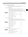
2 STANDARD SYSTEM FUNCTION
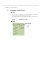
2.1 Message Functions - - - - - - - - - - - - - - - - - - - - - - - - - - - - - 2-2
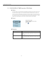
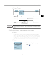
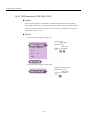
2.1.1 Send Message Function (MSG-SND) - - - - - - - - - - - - - - - - - - - - - - - 2-2
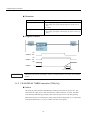
2.1.2 Receive Message Function (MSG-RCV) - - - - - - - - - - - - - - - - - - - - 2-13
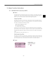
2.2 Trace Functions - - - - - - - - - - - - - - - - - - - - - - - - - - - - - - - 2-22
2.2.1
2.2.2
2.2.3
2.2.4
Trace Function (TRACE) - - - - - - - - - - - - - - - - - - - - - - - - - - - - - - Data Trace Read Function (DTRC-RD) - - - - - - - - - - - - - - - - - - - - Failure Trace Read Function (FTRC-RD) - - - - - - - - - - - - - - - - - - - Inverter Trace Read Function (ITRC-RD) - - - - - - - - - - - - - - - - - - - -
2-22
2-23
2-26
2-31
2.3 Inverter Functions - - - - - - - - - - - - - - - - - - - - - - - - - - - - - 2-34
2.3.1 Inverter Constant Write Function (ICNS-WR) - - - - - - - - - - - - - - - - - 2-34
2.3.2 Inverter Constant Read Function (ICNS-RD) - - - - - - - - - - - - - - - - - 2-39
2.4 Other Functions - - - - - - - - - - - - - - - - - - - - - - - - - - - - - - - 2-42
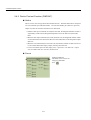
2.4.1 Counter Function (COUNTER) - - - - - - - - - - - - - - - - - - - - - - - - - - - 2-42
2.4.2 First-in First-out Function (FINFOUT)- - - - - - - - - - - - - - - - - - - - - - - 2-44
viii
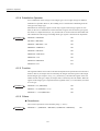
Appendix A Expression
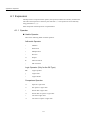
A.1 Expression - - - - - - - - - - - - - - - - - - - - - - - - - - - - - - - - - - - A-2
A.1.1 Operator - - - - - - - - - - - - - - - - - - - - - - - - - - - - - - - - - - - - - - - - - - - A-2
A.1.2 Operand - - - - - - - - - - - - - - - - - - - - - - - - - - - - - - - - - - - - - - - - - - - A-3
A.1.3 Function - - - - - - - - - - - - - - - - - - - - - - - - - - - - - - - - - - - - - - - - - - - A-4
A.2 Recognizable Expression - - - - - - - - - - - - - - - - - - - - - - - - - A-5
A.2.1 Arithmetic Operator - - - - - - - - - - - - - - - - - - - - - - - - - - - - - - - - - - - A-5
A.2.2 Comparison Operator - - - - - - - - - - - - - - - - - - - - - - - - - - - - - - - - - - A-5
A.2.3 Logic Operator - - - - - - - - - - - - - - - - - - - - - - - - - - - - - - - - - - - - - - - A-5
A.2.4 Substitution Operator - - - - - - - - - - - - - - - - - - - - - - - - - - - - - - - - - - A-6
A.2.5 Function - - - - - - - - - - - - - - - - - - - - - - - - - - - - - - - - - - - - - - - - - - - A-6
A.2.6 Others- - - - - - - - - - - - - - - - - - - - - - - - - - - - - - - - - - - - - - - - - - - - - A-6
A.3 Application to Ladder Program - - - - - - - - - - - - - - - - - - - - - A-8
A.3.1 Conditional Expression of IF Instruction - - - - - - - - - - - - - - - - - - - - - A-8
A.3.2 Conditional Expression of WHILE Instruction - - - - - - - - - - - - - - - - - A-8
A.3.3 Operational Expression of EXPRESSION Instruction- - - - - - - - - - - - A-9
ix
1
1
Ladder Program Instructions
This chapter describes the details of ladder program instructions.
1.1 Relay Circuit Instructions - - - - - - - - - - - - - - - - - - - - - - - - - - 1-4
1.1.1 N.O. Contact Instruction (NOC) - - - - - - - - - - - - - - - - - - - - - - - - - - - - 1-4
1.1.2 N.C. Contact Instruction (NCC) - - - - - - - - - - - - - - - - - - - - - - - - - - - - 1-5
1.1.3 10-MS ON-DELAY TIMER Instruction (TON [10ms]) - - - - - - - - - - - - - 1-6
1.1.4 10-MS OFF-DELAY TIMER Instruction (TOFF [10ms]) - - - - - - - - - - - 1-7
1.1.5 1-S ON-DELAY TIMER Instruction (TON [1s]) - - - - - - - - - - - - - - - - - 1-8
1.1.6 1-S OFF-DELAY TIMER Instruction (TOFF [1s]) - - - - - - - - - - - - - - - 1-10
1.1.7 RISING PULSE Instruction (ON-PLS) - - - - - - - - - - - - - - - - - - - - - - 1-11
1.1.8 FALLING PULSE Instruction (OFF-PLS) - - - - - - - - - - - - - - - - - - - - 1-13
1.1.9 COIL Instruction (COIL) - - - - - - - - - - - - - - - - - - - - - - - - - - - - - - - - 1-14
1.1.10 SET COIL Instruction (S-COIL) - - - - - - - - - - - - - - - - - - - - - - - - - - 1-15
1.1.11 RESET COIL Instruction (R-COIL) - - - - - - - - - - - - - - - - - - - - - - - - 1-17
1.2 Numeric Operation Instructions - - - - - - - - - - - - - - - - - - - - 1-19
1.2.1 STORE Instruction (STORE) - - - - - - - - - - - - - - - - - - - - - - - - - - - 1.2.2 ADDITION Instruction (ADD) - - - - - - - - - - - - - - - - - - - - - - - - - - - 1.2.3 EXTENDED ADDITION Instruction (ADDX) - - - - - - - - - - - - - - - - - 1.2.4 SUBTRACTION Instruction (SUB) - - - - - - - - - - - - - - - - - - - - - - - - 1.2.5 EXTENDED SUBTRACTION Instruction (SUBX) - - - - - - - - - - - - - 1.2.6 MULTIPLICATION Instruction (MUL) - - - - - - - - - - - - - - - - - - - - - - 1.2.7 DIVISION Instruction (DIV) - - - - - - - - - - - - - - - - - - - - - - - - - - - - - 1.2.8 MOD Instruction (MOD) - - - - - - - - - - - - - - - - - - - - - - - - - - - - - - - 1.2.9 REM Instruction (REM) - - - - - - - - - - - - - - - - - - - - - - - - - - - - - - - 1.2.10 INC Instruction (INC) - - - - - - - - - - - - - - - - - - - - - - - - - - - - - - - - 1.2.11 DEC Instruction (DEC) - - - - - - - - - - - - - - - - - - - - - - - - - - - - - - - 1.2.12 ADD TIME Instruction (TMADD) - - - - - - - - - - - - - - - - - - - - - - - - 1.2.13 SUBTRACT TIME Instruction (TMSUB) - - - - - - - - - - - - - - - - - - - 1.2.14 SPEND TIME Instruction (SPEND) - - - - - - - - - - - - - - - - - - - - - - 1.2.15 SIGN INVERSION Instruction (INV) - - - - - - - - - - - - - - - - - - - - - - 1.2.16 1’S COMPLEMENT Instruction (COM) - - - - - - - - - - - - - - - - - - - - 1.2.17 ABSOLUTE VALUE CONVERSION Instruction (ABS) - - - - - - - - - 1.2.18 BINARY CONVERSION Instruction (BIN) - - - - - - - - - - - - - - - - - - 1-1
1-19
1-21
1-23
1-24
1-27
1-28
1-31
1-33
1-34
1-35
1-36
1-38
1-39
1-41
1-43
1-44
1-45
1-46
1 Ladder Program Instructions
1.2.19 BCD CONVERSION Instruction (BCD) - - - - - - - - - - - - - - - - - - - - 1.2.20 PARITY CONVERSION Instruction (PARITY) - - - - - - - - - - - - - - - 1.2.21 ASCII CONVERSION Instruction (ASCII) - - - - - - - - - - - - - - - - - - 1.2.22 ASCII CONVERSION 2 Instruction (BINASC) - - - - - - - - - - - - - - - 1.2.23 ASCII CONVERSION 3 Instruction (ASCBIN) - - - - - - - - - - - - - - - -
1-48
1-50
1-51
1-52
1-53
1.3 Logical Operation/Comparison Instructions - - - - - - - - - - - - 1-55
1.3.1 AND Instruction (AND) - - - - - - - - - - - - - - - - - - - - - - - - - - - - - - - - 1.3.2 OR Instruction (OR) - - - - - - - - - - - - - - - - - - - - - - - - - - - - - - - - - - 1.3.3 XOR Instruction (XOR) - - - - - - - - - - - - - - - - - - - - - - - - - - - - - - - - 1.3.4 Comparison Instruction (<) - - - - - - - - - - - - - - - - - - - - - - - - - - - - - 1.3.5 Comparison Instruction (<=) - - - - - - - - - - - - - - - - - - - - - - - - - - - - 1.3.6 Comparison Instruction (=) - - - - - - - - - - - - - - - - - - - - - - - - - - - - - 1.3.7 Comparison Instruction (!=) - - - - - - - - - - - - - - - - - - - - - - - - - - - - - 1.3.8 Comparison Instruction (>=) - - - - - - - - - - - - - - - - - - - - - - - - - - - - 1.3.9 Comparison Instruction (>) - - - - - - - - - - - - - - - - - - - - - - - - - - - - - 1.3.10 RANGE CHECK Instruction (RCHK) - - - - - - - - - - - - - - - - - - - - - -
1-55
1-56
1-57
1-59
1-60
1-61
1-62
1-63
1-64
1-65
1.4 Program Control Instructions - - - - - - - - - - - - - - - - - - - - - - 1-68
1.4.1 SUB-DRAWING CALL Instruction (SEE) - - - - - - - - - - - - - - - - - - - 1.4.2 MOTION PROGRAM CALL Instruction (MSEE) - - - - - - - - - - - - - - 1.4.3 FUNCTION CALL Instruction (FUNC) - - - - - - - - - - - - - - - - - - - - - 1.4.4 DIRECT INPUT STRING Instruction (INS) - - - - - - - - - - - - - - - - - - 1.4.5 DIRECT OUTPUT STRING Instruction (OUTS) - - - - - - - - - - - - - - 1.4.6 EXTENSION PROGRAM CALL Instruction (XCALL) - - - - - - - - - - - 1.4.7 WHILE Instruction (WHILE, END_WHILE) - - - - - - - - - - - - - - - - - - 1.4.8 IF Instruction (IF, END_IF) - - - - - - - - - - - - - - - - - - - - - - - - - - - - - 1.4.9 IF Instruction (IF, ELSE, END_IF) - - - - - - - - - - - - - - - - - - - - - - - - 1.4.10 FOR Instruction (FOR, END_FOR) - - - - - - - - - - - - - - - - - - - - - - 1.4.11 EXPRESSION Instruction (EXPRESSION) - - - - - - - - - - - - - - - - - -
1-68
1-69
1-70
1-72
1-74
1-76
1-77
1-79
1-80
1-82
1-84
1.5 Basic Function Instructions - - - - - - - - - - - - - - - - - - - - - - - 1-85
1.5.1 SQUARE ROOT Instruction (SQRT) - - - - - - - - - - - - - - - - - - - - - - 1.5.2 SINE Instruction (SIN) - - - - - - - - - - - - - - - - - - - - - - - - - - - - - - - - 1.5.3 COSINE Instruction (COS) - - - - - - - - - - - - - - - - - - - - - - - - - - - - - 1.5.4 TANGENT Instruction (TAN) - - - - - - - - - - - - - - - - - - - - - - - - - - - - 1.5.5 ARC SINE Instruction (ASIN) - - - - - - - - - - - - - - - - - - - - - - - - - - - 1.5.6 ARC COSINE Instruction (ACOS) - - - - - - - - - - - - - - - - - - - - - - - - 1.5.7 ARC TANGENT Instruction (ATAN) - - - - - - - - - - - - - - - - - - - - - - - 1.5.8 EXPONENT Instruction (EXP) - - - - - - - - - - - - - - - - - - - - - - - - - - - 1.5.9 NATURAL LOGARITHM Instruction (LN) - - - - - - - - - - - - - - - - - - - 1.5.10 COMMON LOGARITHM Instruction (LOG) - - - - - - - - - - - - - - - - - -
1-85
1-87
1-88
1-90
1-91
1-92
1-93
1-94
1-95
1-96
1.6 Data Manipulation Instructions - - - - - - - - - - - - - - - - - - - - - 1-98
1.6.1 BIT ROTATION LEFT Instruction (ROTL) - - - - - - - - - - - - - - - - - - - - 1-98
1.6.2 BIT ROTATION RIGHT Instruction (ROTR) - - - - - - - - - - - - - - - - - - 1-99
1.6.3 MOVE BITS Instruction (MOVB) - - - - - - - - - - - - - - - - - - - - - - - - - 1-101
1.6.4 MOVE WORD Instruction (MOVW) - - - - - - - - - - - - - - - - - - - - - - - 1-103
1.6.5 EXCHANGE Instruction (XCHG) - - - - - - - - - - - - - - - - - - - - - - - - - 1-105
1.6.6 SET WORDS Instruction (SETW) - - - - - - - - - - - - - - - - - - - - - - - - 1-106
1.6.7 BYTE-TO-WORD EXPANSION Instruction (BEXTD) - - - - - - - - - - - 1-108
1.6.8 WORD-TO-WORD COMPRESSION Instruction (BPRESS) - - - - - - 1-110
1.6.9 BINARY SEARCH Instruction (BSRCH) - - - - - - - - - - - - - - - - - - - - 1-111
1-2
1.6.10 SORT Instruction (SORT) - - - - - - - - - - - - - - - - - - - - - - - - - - - - - 1-113
1.6.11 BIT SHIFT LEFT Instruction (SHFTL) - - - - - - - - - - - - - - - - - - - - - 1-114
1.6.12 BIT SHIFT RIGHT Instruction (SHFTR) - - - - - - - - - - - - - - - - - - - - 1-115
1.6.13 COPY WORD Instruction (COPYW) - - - - - - - - - - - - - - - - - - - - - - 1-116
1.6.14 BYTE SWAP Instruction (BSWAP) - - - - - - - - - - - - - - - - - - - - - - - 1-118
1.7 DDC Instructions - - - - - - - - - - - - - - - - - - - - - - - - - - - - - 1-120
1.7.1 DEAD ZONE A Instruction (DZA) - - - - - - - - - - - - - - - - - - - - - - - - - 1-120
1.7.2 DEAD ZONE B Instruction (DZB) - - - - - - - - - - - - - - - - - - - - - - - - - 1-122
1.7.3 UPPER/LOWER LIMIT Instruction (LIMIT) - - - - - - - - - - - - - - - - - - 1-124
1.7.4 PI CONTROL Instruction (PI) - - - - - - - - - - - - - - - - - - - - - - - - - - - - 1-127
1.7.5 PD CONTROL Instruction (PD) - - - - - - - - - - - - - - - - - - - - - - - - - - 1-131
1.7.6 PID CONTROL Instruction (PID) - - - - - - - - - - - - - - - - - - - - - - - - - 1-135
1.7.7 FIRST-ORDER LAG Instruction (LAG) - - - - - - - - - - - - - - - - - - - - - 1-139
1.7.8 PHASE LEAD/LAG Instruction (LLAG) - - - - - - - - - - - - - - - - - - - - - 1-142
1.7.9 FUNCTION GENERATOR Instruction (FGN) - - - - - - - - - - - - - - - - - 1-144
1.7.10 INVERSE FUNCTION GENERATOR Instruction (IFGN) - - - - - - - - 1-147
1.7.11 LINEAR ACCELERATOR/DECELERATOR 1 Instruction (LAU) - - - 1-151
1.7.12 LINEAR ACCELERATOR/DECELERATOR 2 Instruction (SLAU) - - 1-155
1.7.13 PULSE WIDTH MODULATION Instruction (PWM) - - - - - - - - - - - - 1-163
1.8 Table Data Manipulation Instructions - - - - - - - - - - - - - - - 1-166
1.8.1 BLOCK READ Instruction (TBLBR) - - - - - - - - - - - - - - - - - - - - - - - 1-166
1.8.2 BLOCK WRITE Instruction (TBLBW) - - - - - - - - - - - - - - - - - - - - - - 1-168
1.8.3 ROW SEARCH Instruction (TBLSRL) - - - - - - - - - - - - - - - - - - - - - - 1-170
1.8.4 COLUMN SEARCH Instruction (TBLSRC) - - - - - - - - - - - - - - - - - - 1-171
1.8.5 BLOCK CLEAR Instruction (TBLCL) - - - - - - - - - - - - - - - - - - - - - - - 1-173
1.8.6 BLOCK MOVE Instruction (TBLMV) - - - - - - - - - - - - - - - - - - - - - - - 1-175
1.8.7 QUEUE TABLE READ Instructions (QTBLR, QTBLRI) - - - - - - - - - - 1-177
1.8.8 QUEUE TABLE WRITE Instructions (QTBLW, QTBLWI) - - - - - - - - - 1-179
1.8.9 QUEUE POINTER CLEAR Instruction (QTBLCL) - - - - - - - - - - - - - 1-182
1-3
1
1 Ladder Program Instructions
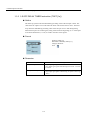
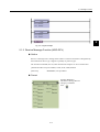
1.1.1 N.O. Contact Instruction (NOC)
1.1 Relay Circuit Instructions
1.1.1 N.O. Contact Instruction (NOC)
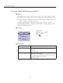
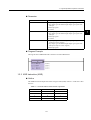
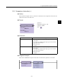
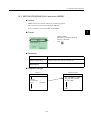
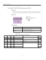
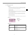
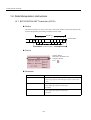
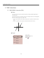
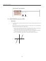
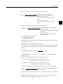
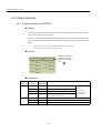
Outline
The NOC sets the value of the bit output to ON if the value of the referenced register is 1
(ON), and to OFF is the value of the referenced register is 0 (OFF).
Format
Symbol: NOC
Full Name: NO Contact
Category: RELAY
Icon:
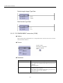
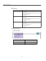
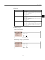
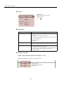
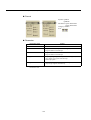
Parameter
Parameter Name
Setting
Relay No.
• Any bit type register
• Any bit type register with subscript
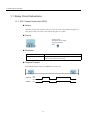
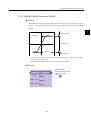
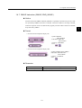
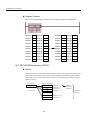
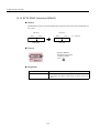
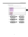
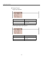
Program Example
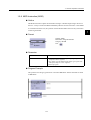
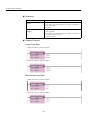
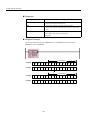
When MW000100 becomes ON, MB000101 becomes ON.
MB000100
ON
OFF
MB000101
ON
OFF
1-4
1.1 Relay Circuit Instructions
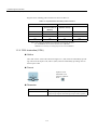
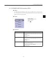
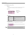
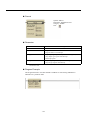
1.1.2 N.C. Contact Instruction (NCC)
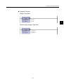
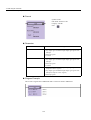
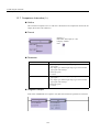
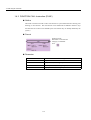
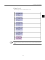
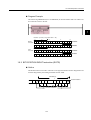
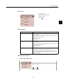
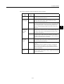
Outline
The NCC sets the value of the bit output to OFF when the value of the referenced register is
1 (ON), and to ON when the value of the referenced register is 0 (OFF).
Format
Symbol: NCC
Full Name: NC Contact
Category: RELAY
Icon:
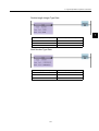
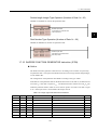
Parameter
Parameter Name
Setting
Relay No.
• Any bit type register
• Any bit type register with subscript
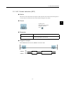
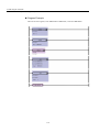
Program Example
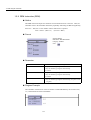
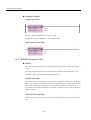
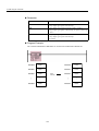
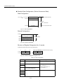
When MB000100 becomes ON, MB000101 becomes OFF.
MB000100
ON
OFF
MB000101
ON
OFF
1-5
1
1 Ladder Program Instructions
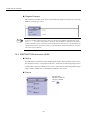
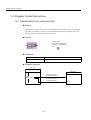
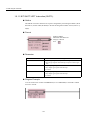
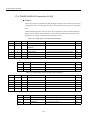
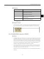
1.1.3 10-MS ON-DELAY TIMER Instruction (TON [10ms])
1.1.3 10-MS ON-DELAY TIMER Instruction (TON [10ms])
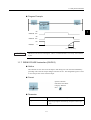
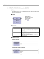
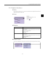
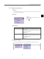
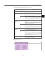
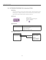
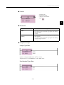
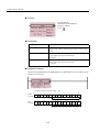
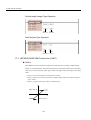
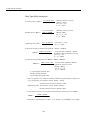
Outline
The TON [10ms] is executed while the immediately-preceding value of the bit input is ON.
The value of the bit output is set to ON when the timer value reaches the set value. The
timer stops when the immediately-preceding value of the bit input is set to OFF during timing. When the bit input is set to ON again, timing restarts from the beginning (0). A value
equal to the actual timed time (10 ms Unit) is stored in the timer value register.
Format
Symbol: TON [10ms]
Full Name: On-Delay Timer [10ms]
Category: RELAY
Icon:
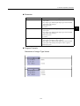
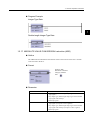
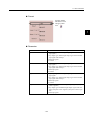
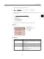
Parameter
Parameter Name
Setting
Set (set value)
• Any integer type register
• Any integer type register with subscript (0 to 65535: in 0.01 sec
unit)
• Constant
Count (timer value)
• Any integer type register (except for # and C registers)
• Any integer type register with subscript (except for # and C registers)
1-6
1.1 Relay Circuit Instructions
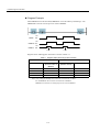
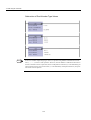
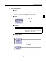
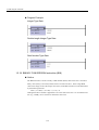
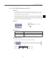
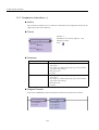
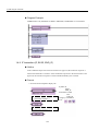
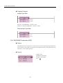
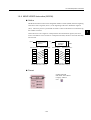
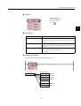
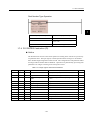
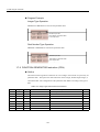
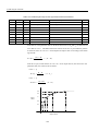
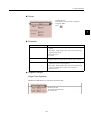
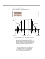
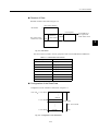
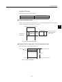
Program Example
1
ON
MB000100 OFF
ON
MB000101 OFF
500
MB000011
0
5.00s-Ts
(Ts = Scan set value)
IMPORTANT
MW00011 works as timer count register. Thus, it is essential that there is no overlap. Set an unused
register.
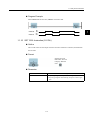
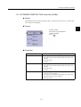
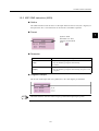
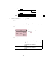
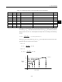
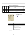
1.1.4 10-MS OFF-DELAY TIMER Instruction (TOFF [10ms])
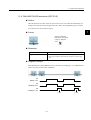
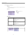
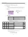
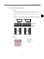
Outline
The TOFF [10ms] is executed while the immediately-preceding value of the bit input is
OFF. The value of the bit output is set to OFF when the timer value reaches the set value.
The timer stops when the immediately-preceding value of the bit input is set to ON during
timing.When the bit input is set to OFF again, timing restarts from the beginning (0). A
value equal to the actual timed time (10 ms Unit) is stored in the timer value register.
Format
Symbol: TOFF [10ms]
Full Name: Off-Delay Timer [10 ms]
Category: RELAY
Icon:
1-7
1 Ladder Program Instructions
1.1.5 1-S ON-DELAY TIMER Instruction (TON [1s])
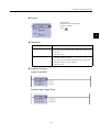
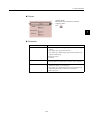
Parameter
Parameter Name
Setting
Set (set value)
• Any integer type register
• Any integer type register with subscript (0 to 65535: 0.01 sec
unit)
• Constant
Count (timer value)
• Any integer type register (except for # and C registers)
• Any integer type register with subscript (except for # and C registers)
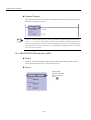
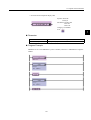
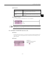
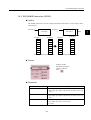
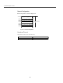
Program Example
ON
MB000100 OFF
ON
MB000101 OFF
500
MB000011
0
500s-Ts
(Ts = Scan set value)
IMPORTANT
MW00011 works as timer count register. Thus, it is essential that there is no overlap. Set an unused
register.
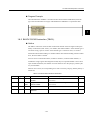
1.1.5 1-S ON-DELAY TIMER Instruction (TON [1s])
Outline
The TON [1s] times while the immediately-preceding value of the bit input is ON. The
value of the bit output is set to ON when the timer value reaches the set value. The timer
stops when the immediately-preceding value of the bit input is set to ON during timing.
When the bit input is set to OFF again, timing restarts from the beginning (0). A value equal
to the actual timed time (1 s Unit) is stored in the timer value register.
1-8
1.1 Relay Circuit Instructions
Format
Symbol: TON [1s]
Full Name: On-Delay Timer [1s]
Category: RELAY
Icon:
1
Parameter
Parameter Name
Setting
Set (set value)
• Any integer type register
• Any integer type register with subscript (0 to 65535: 1 sec unit)
• Constant
Count (timer value)
• Any integer type register (except for # and C registers)
• Any integer type register with subscript (except for # and C registers)
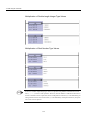
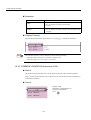
Program Example
ON
MB000100 OFF
ON
MB000101 OFF
500
MB000011
0
500s-Ts
(Ts = Scan set value)
IMPORTANT
MW00011 works as timer count register. Thus, it is essential that there is no overlap. Set an unused
register.
1-9
1 Ladder Program Instructions
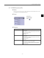
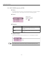
1.1.6 1-S OFF-DELAY TIMER Instruction (TOFF [1s])
1.1.6 1-S OFF-DELAY TIMER Instruction (TOFF [1s])
Outline
The TOFF [1s] times while the immediately-preceding value of the bit input is OFF. The
value of the bit output is set to OFF when the timer value reaches the set value. The timer
stops when the immediately-preceding value of the bit input is set to ON during timing.
When the bit input is set to OFF again, timing restarts from the beginning (0). A value equal
to the actual timed time (1 s Unit) is stored in the timer value register.
Format
Symbol: TOFF [1s]
Full Name: Off-Delay Timer [1s]
Category: RELAY
Icon:
Parameter
Parameter Name
Setting
Set (set value)
• Any integer type register
• Any integer type register with subscript (0 to 65535: 1 sec unit)
• Constant
Count (timer value)
• Any integer type register (except for # and C registers)
• Any integer type register with subscript (except for # and C registers)
1-10
1.1 Relay Circuit Instructions
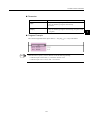
Program Example
1
ON
MB000100 OFF
ON
MB000101 OFF
500
MB000011
0
500s-Ts
(Ts = Scan set value)
IMPORTANT
MW00011 works as timer count register. Thus, it is essential that there is no overlap. Set an unused
register.
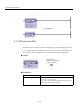
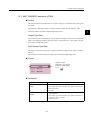
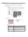
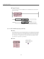
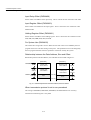
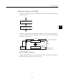
1.1.7 RISING PULSE Instruction (ON-PLS)
Outline
The ON-PLS sets the value of the bit input to ON during one scan when the immediatelypreceding value of the bit output changes from OFF to ON. The designated register is used
to store the previous value of the bit output.
Format
Symbol: ON-PLS
Full Name: Rise Pulse
Category: RELAY
Icon:
Parameter
Parameter Name
Setting
Register No.
• Any bit type register (except for # and C register)
• Any bit type register with subscript (except for # and C registers)
1-11
1 Ladder Program Instructions
1.1.7 RISING PULSE Instruction (ON-PLS)
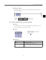
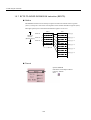
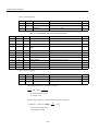
Program Example
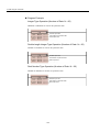
When IB00001 turns ON from OFF, MB000101 turns ON and stays ON during 1 scan.
MB000100 is used to store the previous value of IB00001.
ON
IB00001
OFF
ON
MB000100 OFF
ON
MB000101 OFF
1 scan
1 scan
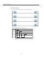
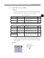
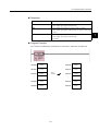
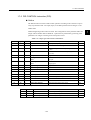
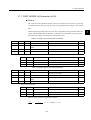
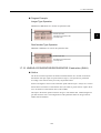
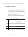
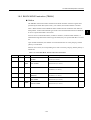
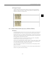
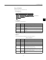
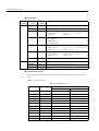
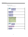
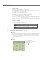
Register status of Rising pulse instruction is shown in Table 1.1.
Table 1.1 Register Status with Rising Pulse Instruction
Input
Result
IB00001
MB000100
(Previous value of
IB00001)
MB000100
(IB00001 stored)
MB000101
OFF
OFF
OFF
OFF
OFF
ON
OFF
OFF
ON
OFF
ON
ON
ON
ON
ON
OFF
Note: Case of Program Example, the instruction is used not for rise detection of MB000100 but is used for rise detection of IB00001.
MB000100 is used only for storing the previous value of IB00001.
1-12
1.1 Relay Circuit Instructions
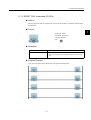
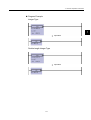
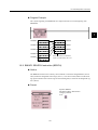
1.1.8 FALLING PULSE Instruction (OFF-PLS)
Outline
The OFF-PLS sets the value of the bit input to ON for one scan when the immediately-preceding value of the bit output changes from ON to OFF. The designated register is used to
store the previous value of the bit output.
1
Format
Symbol: OFF-PLS
Full Name: Fall Pulse
Category: RELAY
Icon:
Parameter
Parameter Name
Setting
Register No.
• Any bit type register (except for # and C register)
• Any bit type register with subscript (except for # and C registers)
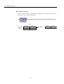
Program Example
When IB00001 turns OFF, MB000101 turns ON and stays ON during 1 scan. MB000100 is
used to store the previous value of IB00001.
ON
IB00001 OFF
ON
MB000100 OFF
ON
MB000101 OFF
1 scan
1-13
1 scan
1 Ladder Program Instructions
1.1.9 COIL Instruction (COIL)
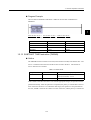
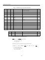
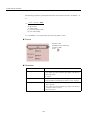
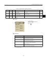
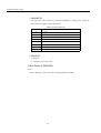
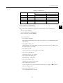
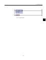
Register status of Falling pulse instruction is shown in Table 1.2.
Table 1.2 Register Status with Falling Pulse Instruction
Input
Result
IB00001
MB000100
(Previous value of
IB00001)
MB000100
(IB00001 stored)
MB000101
OFF
OFF
OFF
OFF
OFF
ON
OFF
ON
ON
OFF
ON
OFF
ON
ON
ON
OFF
Note: Case of Program Example, the instruction is used not for fall detection of MB000100 but is used for fall detection of IB00001.
MB000100 is used only for storing the previous value of IB00001.
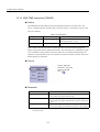
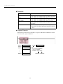
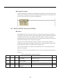
1.1.9 COIL Instruction (COIL)
Outline
The COIL sets the value of the referenced register to 1 (ON) when the immediately-preceding value of the bit input is ON, and to 0 (OFF) when the immediately-preceding value of
the bit input is OFF.
Format
Symbol: COIL
Full Name: Coil
Category: RELAY
Icon:
Parameter
Parameter Name
Setting
Coil No.
• Any bit type register (except for # and C register)
• Any bit type register with subscript (except # and C registers)
1-14
1.1 Relay Circuit Instructions
Program Example
When MB000100 becomes ON, MB000101 becomes ON.
MB000100
ON
OFF
MB000101
ON
OFF
1
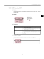
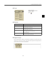
1.1.10 SET COIL Instruction (S-COIL)
Outline
The S-COIL turns ON the output when the execution condition is satisfied, and maintains
the ON state.
Format
Symbol: S-COIL
Full Name: Set Coil
Category: RELAY
Icon:
Parameter
Parameter Name
Setting
Coil No.
• Any bit type register (except for # and C register)
• Any bit type register with subscript (except for # and C registers)
1-15
1 Ladder Program Instructions
1.1.10 SET COIL Instruction (S-COIL)
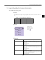
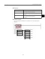
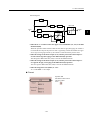
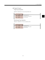
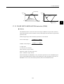
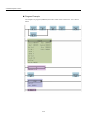
Program Example
Case where the same output destination is designated multiple times.
The above example acts as in the graph below.
MB000000
MB000001
MB000002
MB000003
∗
OB00000
* When OB00000 is OFF, with the "set coil" instruction, OB00000 turns
ON.
1-16
1.1 Relay Circuit Instructions
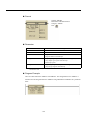
1.1.11 RESET COIL Instruction (R-COIL)
Outline
The R-COIL turns OFF the output when the execution condition is satisfied, and maintains
the OFF state.
Format
1
Symbol: R-COIL
Full Name: Reset Coil
Category: RELAY
Icon:
Parameter
Parameter Name
Setting
Coil No.
• Any bit type register (except for # and C register)
• Any bit type register with subscript (except for # and C registers)
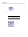
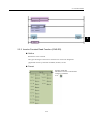
Program Example
Case where the same output destination is designated multiple times.
1-17
1 Ladder Program Instructions
1.1.11 RESET COIL Instruction (R-COIL)
The above example acts as in the graph below.
MB000000
MB000001
MB000002
MB000003
∗
OB00000
* When OB00000 is ON, with the "reset coil" instruction, OB00000 turns
OFF.
1-18
1.2 Numeric Operation Instructions
1.2 Numeric Operation Instructions
1.2.1 STORE Instruction (STORE)
Outline
The STORE instruction stores the contents of Source in the Dest.
1
Format
Symbol: STORE
Full Name: Store
Category: MATH
Icon:
Parameter
Parameter Name
Setting
Source
• Any integer type, double-length integer type and real number
type register
• Any integer type, double-length integer type and real number
type register with subscript
• Subscript register
• Constant
Dest
• Any integer type, double-length integer type and real number
type register (except for # and C registers)
• Any integer type, double-length integer type and real number
type register with subscript (except for # and C registers)
• Subscript register
1-19
1 Ladder Program Instruction
1.2.1 STORE Instruction (STORE)
Program Example
INFO
When a double-length integer type data is stored in an integer type register, the lower 16 bits are stored
as they are. Be careful since an operation error will not occur even if the data to be stored exceeds the
integer range (−32768 to 32767).
1-20
1.2 Numeric Operation Instructions
1.2.2 ADDITION Instruction (ADD)
Outline
The ADD instruction adds integer, double-length integer, and real number values. Source B
is added to Source A and stored in the Dest. If the result of adding integer values is greater
than 32767, an overflow error occurs. If the result of adding double-length integer values is
greater than 2147483647, an overflow error occurs.
1
Format
Symbol: ADD
Full Name: Add
Category: MATH
Icon:
Parameter
Parameter Name
Setting
Source A
• Any integer type, double-length integer type and real number
type register
• Any integer type, double-length integer type and real number
type register with subscript
• Subscript register
• Constant
Source B
• Any integer type, double-length integer type and real number
type register
• Any integer type, double-length integer type and real number
type register with subscript
• Subscript register
• Constant
Dest
• Any integer type, double-length integer type and real number
type register (except for # and C registers)
• Any integer type, double-length integer type and real number
type register with subscript (except for # and C registers)
• Subscript register
1-21
1 Ladder Program Instruction
1.2.2 ADDITION Instruction (ADD)
Program Example
Addition of Integer Type Values
Addition of Real Number Type Values
INFO
In the case of double-length integer type values, an operation using addition and subtraction instructions (+, −, ++, --) will be a 32-bit operation. However, when an addition or subtraction instruction is
used in a remainder correction operation (where a multiplication instruction (×) is the immediately preceding instruction and a division instruction (÷) is the immediately subsequent instruction), the operation will be a 64-bit operation.
1-22
1.2 Numeric Operation Instructions
1.2.3 EXTENDED ADDITION Instruction (ADDX)
Outline
The ADDX instruction adds integer values. Source B is added to Source A and stored in the
Dest. No operation error occurs, even if the operation results in an overflow. Otherwise, the
ADDX is much the same as the ADD.
1
Format
Symbol: ADDX
Full Name: Expanded Add
Category: MATH
Icon:
Parameter
Parameter Name
Setting
Source A
• Any integer type and double-length integer type register
• Any integer type and double-length integer type register with
subscript
• Subscript register
• Constant
Source B
• Any integer type and double-length integer type register
• Any integer type and double-length integer type register with
subscript
• Subscript register
• Constant
Dest
• Any integer type and double-length integer type register
(except for # and C registers)
• Any integer type and double-length integer type register with
subscript (except for # and C registers)
• Subscript register
1-23
1 Ladder Program Instruction
1.2.4 SUBTRACTION Instruction (SUB)
Program Example
This instruction is used in cases where it is desirable that operation errors do not occur in the
addition of integer type values.
INFO
In the case of double-length integer type values, an operation using addition and subtraction instructions (+, −, ++, --) will be a 32-bit operation. However, when an addition or subtraction instruction is
used in a remainder correction operation (where a multiplication instruction (×) is the immediately preceding instruction and a division instruction (÷) is the immediately subsequent instruction), the operation will be a 64-bit operation.
1.2.4 SUBTRACTION Instruction (SUB)
Outline
The SUB instruction subtracts integer, double-length integer, and real number values. Source
B is subtracted to Source A and stored in the Dest. If the result of subtracting integer values
is smaller than -32768, an underflow error occurs. If the result of subtracting double-length
integer values is smaller than -2147483648, an underflow error occurs.
Format
Symbol: SUB
Full Name: Subtract
Category: MATH
Icon:
1-24
1.2 Numeric Operation Instructions
Parameter
Parameter Name
Setting
Source A
• Any integer type, double-length integer type and real number
type register
• Any integer type, double-length integer type and real number
type register with subscript
• Subscript register
• Constant
Source B
• Any integer type, double-length integer type and real number
type register
• Any integer type, double-length integer type and real number
type register with subscript
• Subscript register
• Constant
Dest
• Any integer type, double-length integer type and real number
type register (except for # and C registers)
• Any integer type, double-length integer type and real number
type register with subscript (except for # and C registers)
• Subscript register
Program Example
Subtraction of Integer Type Values
1-25
1
1 Ladder Program Instruction
1.2.4 SUBTRACTION Instruction (SUB)
Subtraction of Real Number Type Values
INFO
In the case of double-length integer type values, an operation using addition and subtraction instructions (+, −, ++, --) will be a 32-bit operation. However, when an addition or subtraction instruction is
used in a remainder correction operation (where a multiplication instruction (×) is the immediately preceding instruction and a division instruction (÷) is the immediately subsequent instruction), the operation will be a 64-bit operation.
1-26
1.2 Numeric Operation Instructions
1.2.5 EXTENDED SUBTRACTION Instruction (SUBX)
Outline
The SUBX instruction subtracts integer values. No operation error occurs, even if the operation results in an underflow.
Format
1
Symbol: SUBX
Full Name: Expanded Subtract
Category: MATH
Icon:
Parameter
Parameter Name
Setting
Source A
• Any integer type and double-length integer type register
• Any integer type and double-length integer type register with
subscript
• Subscript register
• Constant
Source B
• Any integer type and double-length integer type register
• Any integer type and double-length integer type register with
subscript
• Subscript register
• Constant
Dest
• Any integer type and double-length integer type register
(except for # and C registers)
• Any integer type and double-length integer type register with
subscript (except for # and C registers)
• Subscript register
1-27
1 Ladder Program Instruction
1.2.6 MULTIPLICATION Instruction (MUL)
Program Example
This instruction is used in cases where it is desirable that operation errors do not occur in the
subtraction of integer type values.
INFO
In the case of double-length integer type values, an operation using addition and subtraction instructions (+, −, ++, --) will be a 32-bit operation. However, when an addition or subtraction instruction is
used in a remainder correction operation (where a multiplication instruction (×) is the immediately preceding instruction and a division instruction (÷) is the immediately subsequent instruction), the operation will be a 64-bit operation.
1.2.6 MULTIPLICATION Instruction (MUL)
Outline
The MUL instruction multiplies integer, double-length integer, and real number values.
Source B is multiplied to Source A and stored in the Dest.
Format
Symbol: MUL
Full Name: Multiply
Category: MATH
Icon:
1-28
1.2 Numeric Operation Instructions
Parameter
Parameter Name
Setting
Source A
• Any integer type, double-length integer type and real number
type register
• Any integer type, double-length integer type and real number
type register with subscript
• Subscript register
• Constant
Source B
• Any integer type, double-length integer type and real number
type register
• Any integer type, double-length integer type and real number
type register with subscript
• Subscript register
• Constant
Dest
• Any integer type, double-length integer type and real number
type register (except for # and C registers)
• Any integer type, double-length integer type and real number
type register with subscript (except for # and C registers)
• Subscript register
Program Example
Multiplication of Integer Type Values
1-29
1
1 Ladder Program Instruction
1.2.6 MULTIPLICATION Instruction (MUL)
Multiplication of Double-length Integer Type Values
Multiplication of Real Number Type Values
INFO
In the case of double-length integer type values, an operation using addition and subtraction instructions (+, −, ++, --) will be a 32-bit operation. However, when an addition or subtraction instruction is
used in a remainder correction operation (where a multiplication instruction (×) is the immediately preceding instruction and a division instruction (÷) is the immediately subsequent instruction), the operation will be a 64-bit operation.
1-30
1.2 Numeric Operation Instructions
1.2.7 DIVISION Instruction (DIV)
Outline
The DIV instruction divides integer, double-length integer, and real number values. Source
A is divided by Source B and stored in the Dest.
Format
1
Symbol: DIV
Full Name: Divide
Category: MATH
Icon:
Parameter
Parameter Name
Setting
Source A
• Any integer type, double-length integer type and real number
type register
• Any integer type, double-length integer type and real number
type register with subscript
• Subscript register
• Constant
Source B
• Any integer type, double-length integer type and real number
type register
• Any integer type, double-length integer type and real number
type register with subscript
• Subscript register
• Constant
Dest
• Any integer type, double-length integer type and real number
type register (except for # and C registers)
• Any integer type, double-length integer type and real number
type register with subscript (except for # and C registers)
• Subscript register
1-31
1 Ladder Program Instruction
1.2.7 DIVISION Instruction (DIV)
Program Example
Real Number Type Data
1-32
1.2 Numeric Operation Instructions
1.2.8 MOD Instruction (MOD)
Outline
The MOD instruction outputs the remainder of integer or double-length integer division to
the Dest. Always execute the MOD immediately after the division instruction. If the MOD
is executed somewhere else, the operation results obtained before the next entry instruction
cannot be guaranteed.
1
Format
Symbol: MOD
Full Name: Integer Remainder
Category: MATH
Icon:
Parameter
Parameter Name
Setting
Dest
• Any integer type and double-length integer type register
(except for # and C registers)
• Any integer type and double-length integer type register with
subscript (except for # and C registers)
• Subscript register
Program Example
The quotient of an integer type division is stoned in MW00101 and the remainder is stored
in MW00102.
1-33
1 Ladder Program Instruction
1.2.9 REM Instruction (REM)
1.2.9 REM Instruction (REM)
Outline
The REM instruction outputs the remainder of real number division to the Dest. Here, the
remainder refers to the remainder obtained by repeatedly subtracting the Base designated by
the Source. Thus, the n is the number of times subtraction is repeated.
Dest = Source - (Base × n)
(0 ≤ Dest < Base)
Format
Symbol: REM
Full Name: Real Remainder
Category: MATH
Icon:
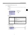
Parameter
Parameter Name
Setting
Source
• Any real number type register
• Any real number type register with subscript
• Constant
Base
• Any real number type register
• Any real number type register with subscript
• Constant
Dest
• Any real number type register (except for # and C register)
• Any real number type register with subscript (except for # and
C register)
Program Example
The remainder of the division of the real number variable MF00200 by the constant value,
1.5, is determined and stored in DF00202.
1-34
1.2 Numeric Operation Instructions
1.2.10 INC Instruction (INC)
Outline
The INC instruction adds 1 to the designated integer or double-length integer register. For
integer registers, no overflow error occurs even if the result of addition exceeds 32767.
Likewise, no overflow error occurs for double-length integer registers.
1
Format
Symbol: INC
Full Name: Increment
Category: MATH
Icon:
Parameter
Parameter Name
Setting
Dest
• Any integer type and double-length integer type register
(except for # and C registers)
• Any integer type and double-length integer type register with
subscript (except for # and C registers)
• Subscript register
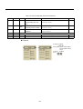
Program Example
⇔
Integer Type
1-35
equivalent
1 Ladder Program Instruction
1.2.11 DEC Instruction (DEC)
⇔
Double-length Integer Type
equivalent
1.2.11 DEC Instruction (DEC)
Outline
The DEC instruction subtracts 1 from the designated integer or double-length integer register. For integer registers, no underflow error occurs even if the result of subtraction is less
than -32768. Likewise, no underflow error occurs for double-length integer registers.
Format
Symbol: DEC
Full Name: Decrement
Category: MATH
Icon:
Parameter
Parameter Name
Setting
Dest
• Any integer type and double-length integer type register
(except for # and C registers)
• Any integer type and double-length integer type register with
subscript (except for # and C registers)
• Subscript register
1-36
1.2 Numeric Operation Instructions
Program Example
Integer Type
⇔
equivalent
⇔
1
equivalent
Double-length Integer Type
1-37
1 Ladder Program Instruction
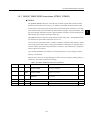
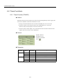
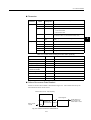
1.2.12 ADD TIME Instruction (TMADD)
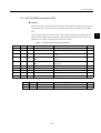
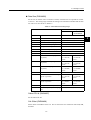
1.2.12 ADD TIME Instruction (TMADD)
Outline
The TMADD instruction adds one time (hours/minutes/seconds) to another time. The
Source is added to the Dest and the result is stored in the Dest. The formats of Source and
Dest are as follows.
Table 1.3 Data Format
Register Offset
Data Contents
Data Range (BCD)
0
Hours/minutes
Upper byte (hours) : 0 to 23
Lower byte (minutes) : 0 to 59
1
Seconds
0000 to 0059
If the contents of the Dest and Source and the operation result are with the appropriate
ranges, the operation will be performed normally. After the operation is completed, the [Status] is turned OFF. If the contents of the Dest and Source are outside the data ranges, the
operation is not performed. In this case, 9999H is stored in the column "second" of the Dest,
and the [Status] is turned ON.
Format
Symbol: TMADD
Full Name: Time Add
Category: MATH
Icon:
Parameter
Parameter Name
Setting
Source
• Any integer type register
• Any integer type register with subscript
Dest
• Any integer type register (except for # and C register)
• Any integer type register with subscript (except for # and C register)
[Status]*
• Any bit type register (except for # and C register)
• Any bit type register with subscript (except for # and C register)
* Possible to omit.
1-38
1.2 Numeric Operation Instructions
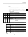
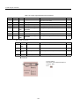
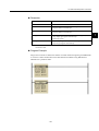
Program Example
The time data in DW0000 to DW00101 is added to the time data in MW00100 to
MW00101.
1
8 hrs 40 min 32 sec + 1 hrs 22 min 16 sec = 10 hrs 2 min 48 sec
(MW00100) (MW00101) (DW00000) (DW00001) (MW00100) (MW00101)
Time Data
Before Execution
After Execution
MW00100
0840H
1002H
MW00101
0032H
0048H
DW00000
0122H
0122H
DW00001
0016H
0016H
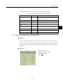
1.2.13 SUBTRACT TIME Instruction (TMSUB)
Outline
The TMSUB instruction subtracts one time (hours/minutes/seconds) from another time. The
Source is subtracted from the Dest and the result is stored in the Dest. The formats of
Source and Dest are as follows.
Table 1.4 Data Format
Register Offset
Data Contents
Data Range (BCD)
0
Hours/minutes
Upper byte (hours) : 0 to 23
Lower byte (minutes) : 0 to 59
1
Seconds
0000 to 0059
If the contents of the Dest and Source are with the appropriate ranges, the operation will be
performed normally. After the operation is completed, the [Status] is turned OFF. If the contents of the Dest and Source are outside the data ranges, the operation is not performed. In
this case, 9999H is stored in the column "second" of the Dest, and the [Status] is turned ON.
1-39
1 Ladder Program Instruction
1.2.13 SUBTRACT TIME Instruction (TMSUB)
Format
Symbol: TMSUB
Full Name: Time Sub
Category: MATH
Icon:
Parameter
Parameter Name
Setting
Source
• Any integer type register
• Any integer type register with subscript
Dest
• Any integer type register (except for # and C register)
• Any integer type register with subscript (except for # and C register)
[Status]*
• Any bit type register (except for # and C register)
• Any bit type register with subscript (except for # and C register)
* Possible to omit.
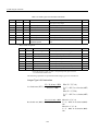
Program Example
The time data in DW0000 to DW0001 is subtracted to the time data in MW00100 to
MW00101.
8 hrs 40 min 32sec + 1 hrs 22 min 16 sec = 7 hrs 18 min 16 sec
(MW00100) (MW00101) (DW00000) (DW00001) (MW00100) (MW00101)
Time Data
Before Execution
After Execution
MW00100
0840H
0718H
MW00101
0032H
0016H
DW00000
0122H
0122H
DW00001
0016H
0016H
1-40
1.2 Numeric Operation Instructions
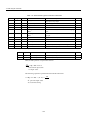
1.2.14 SPEND TIME Instruction (SPEND)
Outline
The SPEND instruction subtracts one time (year/month/day/hours/minutes/seconds) from
another time data and calculates the elapsed time. Source is subtracted from the Dest and the
result is stored in the Dest. The formats of Source and Dest are as follows.
1
Table 1.5 Source Format
Register Offset
Data Contents
Data Range (BCD)
I/O
0
Year (BCD)
0000 to 0099
IN
1
Month/Day (BCD)
Upper byte (month) : 1 to 12
Lower byte (day) : 1 to 31
IN
2
Hours/minutes (BCD)
Upper byte (hours) : 0 to 23
Lower byte (minutes) : 0 to 59
IN
3
Seconds (BCD)
0000 to 0059
IN
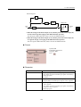
Table 1.6 Dest Format
Register Offset
Data Contents
Data Range (BCD)
I/O
0
Year (BCD)
0000 to 0099
IN/OUT
1
Month/Day (BCD)
Upper byte (month) : 1 to 12
Lower byte (day) : 1 to 31
IN/OUT
2
Hours/minutes (BCD)
Upper byte (hours) : 0 to 23
Lower byte (minutes) : 0 to 59
IN/OUT
3
Seconds (BCD)
0000 to 0059
IN/OUT
4
Total number of seconds
This is the number of records which is obtained
by converting Year/Month/Day/Hour/Minutes/
Seconds, which is the results of operations, to
seconds. (Double-length integer)
IN/OUT
5
If the contents of the Dest, Source and the operation result are with the appropriate ranges,
the operation will be performed normally. After the operation is completed, [Status] is
turned OFF. If the contents of the Dest and Source are outside the data ranges, the operation
is not performed. In this case, 9999H is stored in the column "second" of the Dest, and the
[Status] is turned ON.
Format
Symbol: SPEND
Full Name: Time Spend
Category: MATH
Icon:
1-41
1 Ladder Program Instruction
1.2.14 SPEND TIME Instruction (SPEND)
Parameter
Parameter Name
Setting
Source
• Any integer type register
• Any integer type register with subscript
Dest
• Any integer type register (except for # and C register)
• Any integer type register with subscript (except for # and C register)
[Status]*
• Any bit type register (except for # and C register)
• Any bit type register with subscript (except for # and C register)
* Possible to omit.
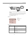
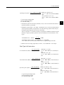
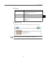
Program Example
The time elapsed from the time data in MW00100 to MW00103 to the time data in
DW00000 to DW00003 is stored to MW00100 - MW00105.
98 yrs 5 mos 11 days 15 hrs 4 min 47 sec - 98 yrs 4 mos 2 days 8 hrs 13 min 8 sec
(MW00100) (MW00101) (MW00102) (MW00103) (DW00000) (DW00101) (DW00102) (DW00103)
= 0 yrs
39 days 6 hrs 51 min 39 sec
(MW00100) (MW00101) (MW00102) (MW00103)
Time Data
INFO
Before Execution
After Execution
MW00100
H0098
H0000
MW00101
H0511
H0039
MW00102
H1504
H0651
MW00103
H0047
H0039
MW00104
−
MW00105
−
3394299 (Decimal)
DW00000
H0098
H0098
DW00001
H0402
H0402
DW00002
H0813
H0813
DW00003
H0008
H0008
In the operation results, the year is counted as 365 days and a leap year is not taken into consideration.
Also, the number of months is not counted. It is counted in days.
1-42
1.2 Numeric Operation Instructions
1.2.15 SIGN INVERSION Instruction (INV)
Outline
The INV instruction inverts the sign of the contents of the Source, and the result is stored in
the Dest.
Format
1
Symbol: INV
Full Name: Inverse
Category: MATH
Icon:
Parameter
Parameter Name
Setting
Source
• Any integer type, double-length integer type and real number
type register
• Any integer type, double-length integer type and real number
type register with subscript
• Subscript register
• Constant
Dest
• Any integer type, double-length integer type and real number
type register (except for # and C registers)
• Any integer type, double-length integer type and real number
type register with subscript (except for # and C registers)
• Subscript register
Program Example
Integer Type Data
1-43
1 Ladder Program Instruction
1.2.16 1’S COMPLEMENT Instruction (COM)
Double-length Integer Type Data
Real Number Type Data
1.2.16 1’S COMPLEMENT Instruction (COM)
Outline
The COM instruction determines the 1’s complement of the contents of the Source and the
result is stored in the Dest.
Format
Symbol: COM
Full Name: Complement
Category: MATH
Icon:
Parameter
Parameter Name
Setting
Source
• Any integer type and double-length integer type register
• Any integer type and double-length integer type register with
subscript
• Subscript register
Dest
• Any integer type and double-length integer type register
(except for # and C registers)
• Any integer type and double-length integer type register with
subscript (except for # and C registers)
• Subscript register
1-44
1.2 Numeric Operation Instructions
Program Example
Integer Type Data
1
Double-length Integer Type Data
1.2.17 ABSOLUTE VALUE CONVERSION Instruction (ABS)
Outline
The ABS instruction determines the absolute value of the contents of the Source and the
result is stored in the Dest.
Format
Symbol: ABS
Full Name: Absolute
Category: MATH
Icon:
Parameter
Parameter Name
Setting
Source
• Any integer type, double-length integer type and real number
type register
• Any integer type, double-length integer type and real number
type register with subscript
• Subscript register
Dest
• Any integer type, double-length integer type and real number
type register (except for # and C registers)
• Any integer type, double-length integer type and real number
type register with subscript (except for # and C registers)
• Subscript register
1-45
1 Ladder Program Instruction
1.2.18 BINARY CONVERSION Instruction (BIN)
Program Example
Integer Type Data
Double-length Integer Type Data
Real Number Type Data
1.2.18 BINARY CONVERSION Instruction (BIN)
Outline
The BIN instruction converts a binary coded decimal (BCD) value in the Source and into a
binary value (binary conversion) and the result is stored in the Dest. If the 4-digit BCD
value in the integer is abcd, the output value (Dest) of the BIN instruction can be determined
by the following formula:
Dest = (a × 1000) + (b × 100) + (c × 10) + d
Although the above formula is applicable even if the value in the Source is not in BCD notation (e.g. 123FH), correct results are obtained in such cases.
1-46
1.2 Numeric Operation Instructions
Format
Symbol: BIN
Full Name: Convert to Binary
Category: MATH
Icon:
1
Parameter
Parameter Name
Setting
Source
• Any integer type and double-length integer type register
• Any integer type and double-length integer type register with
subscript
• Subscript register
Dest
• Any integer type and double-length integer type register
(except for # and C registers)
• Any integer type and double-length integer type register with
subscript (except for # and C registers)
• Subscript register
Program Example
Integer Type Data
Double-length Integer Data
1-47
1 Ladder Program Instruction
1.2.19 BCD CONVERSION Instruction (BCD)
1.2.19 BCD CONVERSION Instruction (BCD)
Outline
The BCD instruction converts a binary value in the Source into a BCD value (BCD conversion) and the result is stored in the Dest. If the 4 - digit decimal value in the Source is abcd,
the output value (Dest) of the BCD instruction can be determined by the following formula:
Dest = (a × 4096) + (b × 256) + (c × 16) + d
Although the above formula is applicable even if the value in the Source cannot be
expressed in BCD notation (e.g. numbers greater than 9999 or negative numbers), correct
results are obtained in such cases.
Format
Symbol: BCD
Full Name: Convert to BCD
Category: MATH
Icon:
Parameter
Parameter Name
Setting
Source
• Any integer type and double-length integer type register
• Any integer type and double-length integer type register with
subscript
• Subscript register
Dest
• Any integer type and double-length integer type register
(except for # and C registers)
• Any integer type and double-length integer type register with
subscript (except for # and C registers)
• Subscript register
1-48
1.2 Numeric Operation Instructions
Program Example
Integer Type Data
1
Double-length Integer Type Data
1-49
1 Ladder Program Instruction
1.2.20 PARITY CONVERSION Instruction (PARITY)
1.2.20 PARITY CONVERSION Instruction (PARITY)
Outline
The PARITY instruction counts the number of bits in the Source that are set to ON (or 1) and
the result is stored in the Dest.
Format
Symbol: PARITY
Full Name: Count ON Bit
Category: MATH
Icon:
Parameter
Parameter Name
Setting
Source
• Any integer type and double-length integer type register
• Any integer type and double-length integer type register with
subscript
• Subscript register
Dest
• Any integer type and double-length integer type register
(except for # and C registers)
• Any integer type and double-length integer type register with
subscript (except for # and C registers)
• Subscript register
Program Example
Integer Type Data
Double-length Integer Type Data
1-50
1.2 Numeric Operation Instructions
1.2.21 ASCII CONVERSION Instruction (ASCII)
Outline
The ASCII instruction converts the specified characters (character string in Source) to the
corresponding ASCII character codes and stores them in the designated Dest. It recognizes
uppercase and lowercase characters separately.
The first character is stored in the lower-place byte of the first word and the second character
is stored in the higher-place byte of the first word. Other characters are stored in the same
way. If the number of characters is odd, the higher-place byte of the last word in the storage
register is set to 0. Up to 32 characters can be entered.
Format
Symbol: ASCII
Full Name: Convert Character to ASCII
Category: MATH
Icon:
Parameter
Parameter Name
Setting
Source
• ASCII characters
Dest
• Any integer type register (except for # and C register)
• Any integer type register with subscript (except for # and C register)
Program Example
The character string "ABCD" is stored in MW00100 to MW00101.
Upper
Lower
MW00100
42H ('B')
41H ('A')
MW00100 = 4241H
MW00101
44H ('D')
43H ('C')
MW00101 = 4443H
1-51
1
1 Ladder Program Instruction
1.2.22 ASCII CONVERSION 2 Instruction (BINASC)
The character string "ABCDEFG" is stored in MW00100 to MW00103.
Upper
Lower
MW00100
42H ('B')
41H ('A')
MW00100 = 4241H
MW00101
44H ('D')
43H ('C')
MW00101 = 4443H
MW00102
46H ('F')
45H ('E')
MW00100 = 4645H
MW00103
00H
47H ('G')
MW00101 = 0047H
"0" is entered in the extra byte.
1.2.22 ASCII CONVERSION 2 Instruction (BINASC)
Outline
The BINASC instruction converts the 16-bit binary data stored in the Source into four-digit
hexadecimal ASCII character codes and stores them in the designated Dest (two words).
Format
Symbol: BINASC
Full Name: Convert Binary to ASCII
Category: MATH
Icon:
Parameter
Parameter Name
Setting
Source
• Any integer type register
• Any integer type register with subscript
• Constant
Dest
• Any integer type register (except for # and C register)
• Any integer type register with subscript (except for # and C register)
1-52
1.2 Numeric Operation Instructions
Program Example
The "1234H" binary is converted to a for digit hexadecimal ASICII code and stored in
MW00100 to MW00101.
1
Upper
Lower
MW00100
32H ('2')
31H ('1')
MW00100 = 3231H
MW00101
34H ('4')
33H ('3')
MW00101 = 3433H
1.2.23 ASCII CONVERSION 3 Instruction (ASCBIN)
Outline
The ASCBIN instruction converts four-digit hexadecimal ASCII character codes in the
Source into 16-bit binary data and stores it in the Dest.
Format
Symbol : ASCBIN
Full Name : Convert ASCII to Binary
Category : MATH
Icon :
Parameter
Parameter Name
Setting
Source
• Any integer type register
• Any integer type register with subscript
Dest
• Any integer type register (except for # and C register)
• Any integer type register with subscript (except for # and C register)
1-53
1 Ladder Program Instruction
1.2.23 ASCII CONVERSION 3 Instruction (ASCBIN)
Program Example
The for-byte ASCII code stored in MW00100 to MW00101 is converted to two-byte binary
data, and the result is stored in MW00200.
Source
Upper
Lower
MW00100
32H ('2')
31H ('1')
MW00101
34H ('4')
33H ('3')
1-54
MW00200
Upper
Lower
12H
34H
1.3 Logical Operation/Comparison Instructions
1.3 Logical Operation/Comparison Instructions
1.3.1 AND Instruction (AND)
Outline
The AND instruction outputs the logical product (AND) of Source A and Source B to the
1
Dest.
Table 1.7 1 bit Truth Table for the Logical Product
Source A
Source B
Dest
0
0
0
0
1
0
1
0
0
1
1
1
Format
Symbol: AND
Full Name: AND
Category: LOGIC
Icon:
Parameter
Parameter Name
Setting
Source A
• Any integer type and double-length integer type register
• Any integer type and double-length integer type register with
subscript
• Subscript register
• Constant
Source B
• Any integer type and double-length integer type register
• Any integer type and double-length integer type register with
subscript
• Subscript register
• Constant
Dest
• Any integer type and double-length integer type register
(except for # and C register)
• Any integer type and double-length integer type register with
subscript (except for # and C register)
• Subscript register
1-55
1 Ladder Program Instruction
1.3.2 OR Instruction (OR)
Program Example
The logical product of MW000100 and a constant is stored in MW00101.
1.3.2 OR Instruction (OR)
Outline
The OR instruction outputs the logical sum (OR) of Source A and Source B to the Dest.
Table 1.8 1 bit Truth Table for the Logical Sum
Source A
Source B
Dest
0
0
0
0
1
1
1
0
1
1
1
1
Format
Symbol: OR
Full Name: Inclusive OR
Category: LOGIC
Icon:
1-56
1.3 Logical Operation/Comparison Instructions
Parameter
Parameter Name
Setting
Source A
• Any integer type and double-length integer type register
• Any integer type and double-length integer type register with
subscript
• Subscript register
• Constant
Source B
• Any integer type and double-length integer type register
• Any integer type and double-length integer type register with
subscript
• Subscript register
• Constant
Dest
• Any integer type and double-length integer type register
(except for # and C register)
• Any integer type and double-length integer type register with
subscript (except for # and C register)
• Subscript register
Program Example
The logical sum of MW00100 and a constant is stored in MW00101.
1.3.3 XOR Instruction (XOR)
Outline
The XOR instruction outputs the exclusive logical sum (XOR) of Source A and Source B to
the Dest.
Table 1.9 1 bit Truth Table for the Exclusive Logical Sum
Source A
Source B
Dest
0
0
0
0
1
1
1
0
1
1
1
0
1-57
1
1 Ladder Program Instruction
1.3.3 XOR Instruction (XOR)
Format
Symbol: XOR
Full Name: Exclusive OR
Category: LOGIC
Icon:
Parameter
Parameter Name
Setting
Source A
• Any integer type and double-length integer type register
• Any integer type and double-length integer type register with
subscript
• Subscript register
• Constant
Source B
• Any integer type and double-length integer type register
• Any integer type and double-length integer type register with
subscript
• Subscript register
• Constant
Dest
• Any integer type and double-length integer type register
(except for # and C register)
• Any integer type and double-length integer type register with
subscript (except for # and C register)
• Subscript register
Program Example
The exclusive logical sum of MW00100 and a constant is stored in MW00101.
1-58
1.3 Logical Operation/Comparison Instructions
1.3.4 Comparison Instruction (<)
Outline
This instruction compare Source A with Source B and stores the comparison result in the bit
output (the result is ON when true).
Format
1
Symbol: <
Full Name: Less Than (A < B)
Category: LOGIC
Icon:
Parameter
Parameter Name
Setting
Source A
• Any integer type, double-length integer type and real number
type register
• Any integer type, double-length integer type and real number
type register with subscript
• Subscript register
• Constant
Source B
• Any integer type, double-length integer type and real number
type register
• Any integer type, double-length integer type and real number
type register with subscript
• Subscript register
• Constant
Program Example
If the value of MW00100 is smaller than 100, after the instructions operation are executed.
1-59
1 Ladder Program Instruction
1.3.5 Comparison Instruction (<=)
1.3.5 Comparison Instruction (<=)
Outline
This instruction compare Source A with Source B and stores the comparison result in the bit
output (the result is ON when true).
Format
Symbol: <=
Full Name: Less Than or Equal (A <= B)
Category: LOGIC
Icon:
Parameter
Parameter Name
Setting
Source A
• Any integer type, double-length integer type and real number
type register
• Any integer type, double-length integer type and real number
type register with subscript
• Subscript register
• Constant
Source B
• Any integer type, double-length integer type and real number
type register
• Any integer type, double-length integer type and real number
type register with subscript
• Subscript register
• Constant
Program Example
If the value of MW00100 is under 100, after the instructions operation are executed.
1-60
1.3 Logical Operation/Comparison Instructions
1.3.6 Comparison Instruction (=)
Outline
This instruction compare Source A with Source B and stores the comparison result in the bit
output (the result is ON when true).
Format
1
Symbol: =
Full Name: Equal (A = B)
Category: LOGIC
Icon:
Parameter
Parameter Name
Setting
Source A
• Any integer type, double-length integer type and real number
type register
• Any integer type, double-length integer type and real number
type register with subscript
• Subscript register
• Constant
Source B
• Any integer type, double-length integer type and real number
type register
• Any integer type, double-length integer type and real number
type register with subscript
• Subscript register
• Constant
Program Example
If the value of MW00100 is equal to 100, after the instructions operation are executed.
1-61
1 Ladder Program Instruction
1.3.7 Comparison Instruction (!=)
1.3.7 Comparison Instruction (!=)
Outline
This instruction compare Source A with Source B and stores the comparison result in the bit
output (the result is ON when true).
Format
Symbol: !=
Full Name: Not Equal (A! = B)
Category: LOGIC
Icon:
Parameter
Parameter Name
Setting
Source A
• Any integer type, double-length integer type and real number
type register
• Any integer type, double-length integer type and real number
type register with subscript
• Subscript register
• Constant
Source B
• Any integer type, double-length integer type and real number
type register
• Any integer type, double-length integer type and real number
type register with subscript
• Subscript register
• Constant
Program Example
If the value of MW00100 is not equal to 100, after the instructions operation are executed.
1-62
1.3 Logical Operation/Comparison Instructions
1.3.8 Comparison Instruction (>=)
Outline
This instruction compare Source A with Source B and stores the comparison result in the bit
output (the result is ON when true).
Format
1
Symbol: >=
Full Name: Greater Than or Equal (A >= B)
Category: LOGIC
Icon:
Parameter
Parameter Name
Setting
Source A
• Any integer type, double-length integer type and real number
type register
• Any integer type, double-length integer type and real number
type register with subscript
• Subscript register
• Constant
Source B
• Any integer type, double-length integer type and real number
type register
• Any integer type, double-length integer type and real number
type register with subscript
• Subscript register
• Constant
Program Example
If the value of MW00100 is above 100, after the instructions operation are executed.
1-63
1 Ladder Program Instruction
1.3.9 Comparison Instruction (>)
1.3.9 Comparison Instruction (>)
Outline
This instruction compare Source A with Source B and stores the comparison result in the bit
output (the result is ON when true).
Format
Symbol: >
Full Name: Greater Than (A > B)
Category: LOGIC
Icon:
Parameter
Parameter Name
Setting
Source A
• Any integer type, double-length integer type and real number
type register
• Any integer type, double-length integer type and real number
type register with subscript
• Subscript register
• Constant
Source B
• Any integer type, double-length integer type and real number
type register
• Any integer type, double-length integer type and real number
type register with subscript
• Subscript register
• Constant
Program Example
If the value of MW00100 is bigger than 100, after the instructions operation are executed.
1-64
1.3 Logical Operation/Comparison Instructions
1.3.10 RANGE CHECK Instruction (RCHK)
Outline
The RCHK instruction checks whether the input value in the Input is within the Lower Limit
and Upper Limit, and then outputs the result to the bit output. The contents of the Input are
retained.
Bit output = OFF
Upper limit
Input
Bit output = ON
Lower limit
Bit output = OFF
• If the Input value (Input) is greater than the Lower Limit and less than the Upper Limit,
the result (Bit Output) = ON.
• In the cases other than the above, the result (Bit Output) = OFF.
Format
Symbol: RCHK
Full Name: Range Check
Category: LOGIC
Icon:
1-65
1
1 Ladder Program Instruction
1.3.10 RANGE CHECK Instruction (RCHK)
Parameter
Parameter Name
Setting
Input
• Any integer type, double-length integer type and real number
type register
• Any integer type, double-length integer type and real number
type register with subscript
• Subscript register
• Constant
Lower Limit
• Any integer type, double-length integer type and real number
type register
• Any integer type, double-length integer type and real number
type register with subscript
• Subscript register
• Constant
Upper Limit
• Any integer type, double-length integer type and real number
type register
• Any integer type, double-length integer type and real number
type register with subscript
• Subscript register
• Constant
Program Example
Integer Type Data
Input (MW00100)
Output (DB000000)
-1000 > MW00100
OFF
-1000 <= MW00100 <= 1000
ON
MW00100 >1000
OFF
1-66
1.3 Logical Operation/Comparison Instructions
Double-length Integer Type Data
1
Input (ML00100)
Output (DB000000)
-100000 > ML00100
OFF
-100000 <= ML00100 <= 100000
ON
ML00100 >100000
OFF
Real Number Type Data
Input (DF00100)
Output (DB000000)
-10.5 > DF00100
OFF
-10.5 <= DF00100 <= 10.5
ON
DF00100 >10.5
OFF
1-67
1 Ladder Program Instruction
1.4.1 SUB-DRAWING CALL Instruction (SEE)
1.4 Program Control Instructions
1.4.1 SUB-DRAWING CALL Instruction (SEE)
Outline
The SEE instruction is used to call a sub-drawing from a drawing or to call a sub-sub- drawing from a sub-drawing. Calling is not possible between drawings of different types. For
example, SEE H01 cannot be specified in DWG.L.
Format
Symbol: SEE
Full Name: Call Program
Category: CONTROL
Icon:
Parameter
Parameter Name
Setting
Name
Program Name
Program Example
SEE A01
DWG.A
DWG.A01
Start of execution of
child drawing A01
(SEE)
Name. A01
End of execution of
child drawing A01
1-68
END
1.4 Program Control Instructions
1.4.2 MOTION PROGRAM CALL Instruction (MSEE)
Outline
MSEE instruction is used in referring to the motion program.
This instruction can be referred only from DWG.H.
It is not possible to refer from DWG.A and DWG.L.
1
Format
Symbol: MSEE
Full Name: Call Motion Program
Category: MOTION
Icon:
Parameter
Parameter Name
Setting
Program No.
(Motion Program No.)
• Direct specification: Numerical value of 1-256
• Indirect specification: Register of integer type
Dest
(Work Register)
• Register address (except for # and C registers)
Program Example
DWG H
Motion program
DWG.H
(MSEE)
Program No.
Data
MPM001
VEL [X] 6000 [Y] 6000 ;
MOV [X] 1000 [Y] 1000 ;
MVS [X] 2000 ;
1
DA00000
END
1-69
1 Ladder Program Instruction
1.4.3 FUNCTION CALL Instruction (FUNC)
1.4.3 FUNCTION CALL Instruction (FUNC)
Outline
The FUNC instruction is used to call a user function or system function from a drawing, subdrawing, or user function. The user function to be called must be defined in advance. (System functions do not have to be defined by the user because they are already defined by the
system.)
Format
Symbol: FUNC
Full Name: User Function
Category: CONTROL
Icon:
Parameter
Parameter Name
Setting
Name
Program name
INPUT
Input parameter (the data type depends on function definition)
ADRESS
Address parameter (Address type register)
OUTPUT
Output parameter (the data type depends on function definition)
1-70
1.4 Program Control Instructions
The forms of parameter input and output are shown below.
Input Data
Form
Input Designation
Description
Bit Input
B-VAL
Designates the output to be of a bit type. The bit type data
become the input to the function.
Integer Type
Input
I-VAL
Designates the input to be of an integer type. The contents
(integer data) of the register with the designated number
become the input to the function.
I-REG
Designates the input to be the contents of an integer type
register. The number of the integer type register is designated when referencing the function. The contents (integer
data) of the register with the designated number become
the input to the function.
L-VAL
Designates the input to be of a double-length integer type
register.
When reference the function, the contents (double-length
integer data) of the register with the designated number
become the input to the function.
L-REG
Designates the input to be the contents of a double-length
integer type register. When reference the function, the contents (double-length integer data) of the register with the
designated number become the input to the function.
F-VAL
Designates the input to be of a real number type. The contents (real number data) of the register with the designated
number become the input to the function.
F-REG
Designates the input to be the contents of a real number
type register.
The number of the real number type register is designated
when referencing the function. The contents (real number
data) of the register with the designated number become
the input to the function.
−
Hands over the address of the designated register (an arbitrary integer register) to the function. Only 1 input is
allowed in the case of a user function.
Double-length
Integer Type
Input
Real Number
Type Input
Address Input
Program Example
1-71
1
1 Ladder Program Instruction
1.4.4 DIRECT INPUT STRING Instruction (INS)
1.4.4 DIRECT INPUT STRING Instruction (INS)
Outline
The INS instruction continuously performs direct input to a single module according to the
contents of a previously-set parameter table. INS can only be used for LIO modules.
Format
Symbol : INS
Full Name : Direct Input String
Category : CONTROL
Icon :
Parameter
Parameter Name
Setting
Parameter
• Register address (except for # and C registers)
• Register address with subscript
[Status]*
• Any bit type register (except for # and C registers)
• Any bit type register with subscript
* Possible to omit.
Table 1.10 INS Instruction Parameter/Data
ADR
Type
Symbol
Name
0
W
RSSEL
Module designation 1
1
W
MDSEL
Module designation 2
2
W
STS
Status
Specifications
Input or
Output
Designation of module for performing input<For
details refer to (1) and (2) below>
IN
Output of a bit equivalence of the status for each
word input
OUT
IN
3
W
N
Number of words
Designation of number of continuous input words
IN
4
W
ID1
Input data 1
OUT
•
•
•
•
•
•
If there is an error in the output of input data, 0 is
stored
N+3
W
•
•
•
IDN
•
•
•
Input data N
•
•
•
OUT
Method of Setting RSSEL
Designates the rack/slot where the target module is mounted.
Hexadecimal expression: xxyyH
xx = rack number (01H ≤ xx ≤ 04H)
yy = slot number (00H ≤ yy ≤ 0DH)
1-72
1.4 Program Control Instructions
INFO
The rack number = 1, slot number = 3 with tixation in MP930
Method of Setting MDSEL
F
C
a
8
b
a: Input module type
b: Rack number (1 ≤ b ≤ 4)
c: Slot number (1 ≤ c ≤ 9)
d: Data offset (0 ≤ d ≤ 7)
INFO
4
c
0
d
Hexadecimal:
abcdH
0: Discrete input module
1: Register input module
The input module type = 0, rack number = 1, slot number = 3, data offset = 0 with fixation in MP930
Program Example
Data input from LIO mounted at rack 2, slot 4.
1-73
1
1 Ladder Program Instruction
1.4.5 DIRECT OUTPUT STRING Instruction (OUTS)
1.4.5 DIRECT OUTPUT STRING Instruction (OUTS)
Outline
The OUTS instruction continuously performs direct output to a single module according to
the contents of a previously-set parameter table. OUTS can only be used for LIO modules.
Format
Symbol: OUTS
Full Name: Direct Output String
Category: CONTROL
Icon:
Parameter
Parameter Name
Setting
Parameter
• Register address (except for # and C registers)
• Register address with subscript
[Status]*
• Any bit type register (except for # and C registers)
• Any bit type register with subscript
* Possible to omit.
Table 1.11 OUTS Instruction Parameter/Data
ADR
Type
Symbol
Name
Specifications
0
W
RSSEL
Module designation 1
1
W
MDSEL
Module designation 2
2
W
STS
3
W
4
Input or
Output
Designation of module for performing output∗
IN
Status
Output of a bit equivalence of the status for each
word output
OUT
N
Number of words
Designation of number of words output continuously IN
W
OD1
Output data 1
Setting output data
•
•
•
•
•
•
•
•
•
•
•
•
N+3
W
ODN
Output data N
IN
IN
•
•
•
IN
* Method of setting RSSEL and N (number of words) is the same as for INS.
1-74
1.4 Program Control Instructions
Program Example
Two words output to LIO-01 mounted at rack 3, slot 10.
1
INFO
Two outputs will be done by using the OUTS instruction because local I/O is allocated by default for
MP930.
1-75
1 Ladder Program Instruction
1.4.6 EXTENSION PROGRAM CALL Instruction (XCALL)
1.4.6 EXTENSION PROGRAM CALL Instruction (XCALL)
Outline
The XCALL instruction is used to call an extension program. Extension programs are table
format programs. Although a pulurality of XCALL instructions may be used in one drawing, the same extension program cannot be called more than once.
Format
Symbol: XCALL
Full Name: Call Extended Program
Category: CONTROL
Icon:
Parameter
Parameter Name
Setting
Name
MCTBL: Constant table (M register)
IOTBL: I/O conversion table
ILKTBL: Interlock table
ASMTBL: Parts composition table
Program Example
DWG.x.xx
Expansion Conversion Program
(XCALL)
Name ILKTBL
XCALL ILKTBL
XPEND
The converted ladder
program cannot be
viewed at the Editor.
1-76
1.4 Program Control Instructions
1.4.7 WHILE Instruction (WHILE, END_WHILE)
Outline
Instruction between WHILE and END_WHILE is repeatedly executed as long as the condition specified by WHILE instruction is satisfied. When the condition is no longer satisfied,
instruction sequence is not executed and the program proceeds with the instruction immediately after END_WHILE.
1
Format
• At instruction development display ON
Symbol: WHILE
END_WHILE
Full Name: While Do
End of While
Category: CONTROL
Icon:
,
• At instruction development display OFF
Symbol: WHILE-END_WHILE
Full Name: While Do and
End of While
Category: CONTROL
Icon:
Parameter
Parameter Name
Setting
Conditional Expression
Description by Expression
1-77
1 Ladder Program Instruction
1.4.7 WHILE Instruction (WHILE, END_WHILE)
Program Example
The total for 100 registers, from MW00100 to MW00199, is stored in MW00200.
1-78
1.4 Program Control Instructions
1.4.8 IF Instruction (IF, END_IF)
Outline
If the conditional expression in the IF instruction is approved, the instruction sequence
between IF and END_IF is executed. If the conditional expression in the IF instruction is
not approved, the instruction sequence between IF and END_IF is not executed.
1
Format
• At instruction development display ON
Symbol: IF
END_IF
Full Name: If Then
End of If
Category: CONTROL
Icon:
,
• At instruction development display OFF
Symbol: IF-END_ IF
Full Name: IF Then and
End of If
Category: CONTROL
Icon:
Parameter
Parameter Name
Setting
Conditional Expression
Description by Expression
1-79
1 Ladder Program Instruction
1.4.9 IF Instruction (IF, ELSE, END_IF)
Program Example
If MB000108 is ON, MW00201 is added to MW00200, and MW00201 is incremented.
1.4.9 IF Instruction (IF, ELSE, END_IF)
Outline
If the conditional expression in the IF instruction is approved, the instruction sequence 1
between IF and ELSE is executed. If the conditional expression in the IF instruction is not
approved, the instruction sequence 2 between ELSE and END_IF is executed.
Format
• At instruction development display ON
Symbol: IF
ELSE
END_IF
Full Name: If Then
Else
End of If
Category: CONTROL
Icon:
,
,
1-80
1.4 Program Control Instructions
• At instruction development display OFF
Symbol: IF-ELSEEND_IF
Full Name: IF Then and
Else and
End of If
Category: CONTROL
Icon:
1
Parameter
Parameter Name
Setting
Conditional Expression
Description by Expression
Program Example
MW00011 is set to 0 if MW00010 is positive number, and set to 1 if MW00010 is negative
number.
1-81
1 Ladder Program Instruction
1.4.10 FOR Instruction (FOR, END_FOR)
1.4.10 FOR Instruction (FOR, END_FOR)
Outline
The instruction sequence surrounded by the FOR instruction and the corresponding
END_FOR instruction are executed by the number of times. Variable starts from initial
value (Init) and is incremented by Step on each execution. The instruction sequence is
ended when Variable > Max.
Format
• At instruction development display ON
Symbol: FOR
END_FOR
Full Name: For
End of For
Category: CONTROL
Icon:
,
• At instruction development display OFF
Symbol: FOR-END_FOR
Full Name: For and
End of For
Category: CONTROL
Icon:
1-82
1.4 Program Control Instructions
Parameter
Parameter Name
Setting
Variable
• Any integer type register
• Any integer type register with subscript
• Subscript register (I and J registers)
Init
• Any integer type register
• Any integer type register with subscript
• Subscript register
• Constant
Max
• Any integer type register
• Any integer type register with subscript
• Subscript register
• Constant
Step
• Any integer type register
• Any integer type register with subscript
• Subscript register
• Constant
Program Example
The high byte and low byte, form MW00100 to MW00102, are exchanged.
1-83
1
1 Ladder Program Instruction
1.4.11 EXPRESSION Instruction (EXPRESSION)
1.4.11 EXPRESSION Instruction (EXPRESSION)
Outline
EXPRESSION instruction is composed by one block. It considers on a par with a coil type
component, and an input line has the Instruction of Enable/Disable command. In the block,
Expression box for an operation formula description is prepared, and the description of the
operation formula to 1000 lines is possible.
Format
Symbol: EXPRESSION
Full Name: Expression
Category: CONTROL
Icon:
Parameter
Parameter Name
Setting
Conditional Expression
Description by Expression
Program Example
1-84
1.5 Basic Function Instructions
1.5 Basic Function Instructions
1.5.1 SQUARE ROOT Instruction (SQRT)
Outline
The SQRT instruction calculates the square root of an integer or real number value as the
operation result. The input units and output results for integer and real number values are
different. This instruction cannot be used for double-length integer data.
Integer Type Data
The square root of Source is stored in Dest. The operation result of the SQRT instruction
slightly differs from the square root in mathematical terms. To be more precise, the operation result is expressed by the following formula:
32768∗ sign (A)∗ SQRT (|A|/ 32768)
sign (A): sign of the Source
|A| : absolute value of the Source
In other words, the operation result is equal to the mathematical square root multiplied by
approximately 181.02. If the input is a negative value, the square root of the absolute value
is calculated first and then the negative value of the square root is output as the operation
result.
The maximum error of the output value is +/-2.
Real Number Type Data
The square root of Source is stored in Dest. If the input is a negative value, the square root
of the absolute value is calculated first and then the negative value of the square root is output as the operation result. This instruction can be used in a real number operation.
Format
Symbol: SQRT
Full Name: Square Root
Category: FUNCTION
Icon:
1-85
1
1 Ladder Program Instruction
1.5.1 SQUARE ROOT Instruction (SQRT)
Parameter
Parameter Name
Setting
Source
(Input)
• Any integer type and real number type register
• Any integer type and real number type register with subscript
• Subscript register
• Constant
Dest
(Output)
• Any integer type and real number type register (except for #
and C registers)
• Any integer type and real number type register with subscript
(except for # and C registers)
• Subscript register
Program Example
Integer Type Data
• When the input is a positive number
• When the input is a negative number
Real Number Type Data
• When the input is a positive number
• When the input is a negative number
1-86
1.5 Basic Function Instructions
1.5.2 SINE Instruction (SIN)
Outline
The SIN instruction calculates the sine of an integer or real number value as the operation
result. The input units and output results for integer and real number values are different.
This instruction cannot be used for double-length integer data.
1
Integer Type Data
This instruction can be used between -327.68 and 327.67 degrees. The Source is used as the
input (1 = 0.01 degree) and the operation result is stored in the Dest. Upon output, the operation result is multiplied by 10,000.
If a value outside the range of -327.68 to 327.67 is entered, the correct result cannot be
obtained. For example, if 360.00 is entered, -295.36 degrees will be output as the result.
Real Number Type Data
The Source is used as the input (unit = degrees) and the sine of the input is stored in the Dest.
Format
Symbol: SIN
Full Name: Sine
Category: FUNCTION
Icon:
Parameter
Parameter Name
Setting
Source
(Input)
• Any integer type and real number type register
• Any integer type and real number type register with subscript
• Subscript register
• Constant
Dest
(Output)
• Any integer type and real number type register (except for #
and C registers)
• Any integer type and real number type register with subscript
(except for # and C registers)
• Subscript register
1-87
1 Ladder Program Instruction
1.5.3 COSINE Instruction (COS)
Program Example
Integer Type Data
Input X = 30 degrees (MW00100 = 30∗100 = 3000)
Output SIN (X) = 0.50 (MW00102 = 0.50∗10000 = 5000)
Real Number Type Data
1.5.3 COSINE Instruction (COS)
Outline
The COS instruction calculates the cosine of integer or real number values as the operation
result.
The input units and output results for integer and real number values are different. This
instruction cannot be used for double-length integer data.
Integer Type Data
This instruction can be used between -327.68 and 327.67 degrees. The Source is used as the
input (1 = 0.01 degrees) and the operation result is stored in the Dest. Upon output, the operation result is multiplied by 10,000. If a value outside the range of -327.68 to 327.67 is
entered, the correct result is obtained. For example, if 360.00 is entered, -295.36 degrees is
output as a result.
Real Number Type Data
The Source is used as the input (unit = degrees) and the cosine of the input is stored in the
Dest.
1-88
1.5 Basic Function Instructions
Format
Symbol: COS
Full Name: Cosine
Category: FUNCTION
Icon:
1
Parameter
Parameter Name
Setting
Source
(Input)
• Any integer type and real number type register
• Any integer type and real number type register with subscript
• Subscript register
• Constant
Dest
(Output)
• Any integer type and real number type register (except for #
and C registers)
• Any integer type and real number type register with subscript
(except for # and C registers)
• Subscript register
Program Example
Integer Type Data
Input X = 60 degrees (MW00100 = 60∗100 = 6000)
Output COS (X) = 0.50 (MW00102 = 0.50∗10000 = 500)
Real Number Type Data
1-89
1 Ladder Program Instruction
1.5.4 TANGENT Instruction (TAN)
1.5.4 TANGENT Instruction (TAN)
Outline
The TAN instruction uses the Source as the input (unit = degrees) and stores the tangent of
the input in the Dest. This instruction can be used in a real number operation.
Format
Symbol: TAN
Full Name: Tangent
Category: FUNCTION
Icon:
Parameter
Parameter Name
Setting
Source
(Input)
• Any real number type register
• Any real number type register with subscript
• Constant
Dest
(Output)
• Any real number type register (except for # and C register)
• Any real number type register with subscript (except for # and
C register)
Program Example
The tangent of the input value (X = 45.0 degrees) [TAN (X) = 1.0] is calculated.
INFO
TANGENT Instruction cannot be used for integer type and double-length integer type data.
1-90
1.5 Basic Function Instructions
1.5.5 ARC SINE Instruction (ASIN)
Outline
The ASIN instruction uses the Source as the input and stores the arc sine (unit = degrees) of
the input in the Dest. This instruction can be used in a real number operation.
Format
Symbol: ASIN
Full Name: Arc Sine
Category: FUNCTION
Icon:
Parameter
Parameter Name
Setting
Source
(Input)
• Any real number type register
• Any real number type register with subscript
• Constant
Dest
(Output)
• Any real number type register (except for # and C register)
• Any real number type register with subscript (except for # and
C register)
Program Example
The arc sine of the input value (0.5) [ASIN (0.5) = θ = 30.0 degrees] is calculated.
INFO
ARC SINE Instruction cannot be used for integer type and double-length integer type data.
1-91
1
1 Ladder Program Instruction
1.5.6 ARC COSINE Instruction (ACOS)
1.5.6 ARC COSINE Instruction (ACOS)
Outline
The ACOS instruction uses the Source as the input and stores the arc cosine (unit = degrees)
of the input in the Dest. This instruction can be used in a real number operation.
Format
Symbol: ACOS
Full Name: Arc Cosine
Category: FUNCTION
Icon:
Parameter
Parameter Name
Setting
Source
(Input)
• Any real number type register
• Any real number type register with subscript
• Constant
Dest
(Output)
• Any real number type register (except for # and C register)
• Any real number type register with subscript (except for # and
C register)
Program Example
The arc cosine of the input value (0.5) [ACOS (0.5) = X = 60.0 degrees] is calculated.
INFO
ARC COSINE Instruction cannot be used for integer type and double-length integer type data.
1-92
1.5 Basic Function Instructions
1.5.7 ARC TANGENT Instruction (ATAN)
Outline
The ATAN instruction calculates the arc tangent of integer or real number data as the operation result.
The input units and output results for integer and real number data are different. This
1
instruction cannot be used for double-length integer data.
Integer Type Data
This instruction can be used between -327.68 and 327.67 degrees. The Source is used as the
input (1 = 0.01 degrees) and the operation result is stored in the Dest. Upon output, the operation result is multiplied by 100.
Real Number Type Data
The Source is used as the input (unit = degrees) and the arc tangent of the input is stored in
the Dest.
This instruction cannot be used for integer type and double-length integer data.
Format
Symbol: ATAN
Full Name: Arc Tangent
Category: FUNCTION
Icon:
Parameter
Parameter Name
Setting
Source
(Input)
• Any integer type and real number type register
• Any integer type and real number type register with subscript
• Subscript register
• Constant
Dest
(Output)
• Any integer type and real number type register (except for #
and C registers)
• Any integer type and real number type register with subscript
(except for # and C registers)
• Subscript register
1-93
1 Ladder Program Instruction
1.5.8 EXPONENT Instruction (EXP)
Program Example
Integer Type Data
Input X = 1.00 (MW00100 = 1.00∗100 = 100)
Output X = 45 degrees (MW00102 = 45∗100 = 4500)
Real Number Type Data
1.5.8 EXPONENT Instruction (EXP)
Outline
The EXP instruction uses the Source as the input (x) and stores the natural logarithmic base
(e) to the power of the input (ex) in the Dest as the operation result. This instruction can be
used only in a real number operation.
Format
Symbol: EXP
Full Name: Exponential
Category: FUNCTION
Icon:
1-94
1.5 Basic Function Instructions
Parameter
Parameter Name
Setting
Source
(Input)
• Any real number type register
• Any real number type register with subscript
• Constant
Dest
(Output)
• Any real number type register (except for # and C register)
• Any real number type register with subscript (except for # and
C register)
Program Example
e ( = 2.7183) to the power of the input value (x = 1.0) is calculated.
INFO
Maximum value (3.4 ・・・ E + 38) is stored and an operation error will not occur even if the operation
results of EXP instruction in an overflow.
1.5.9 NATURAL LOGARITHM Instruction (LN)
Outline
The LN instruction uses the Source as the input (x) and stores the natural logarithm (Logex)
of the input in the Dest as the operation result. This instruction can be used only in a real
number operation.
Format
Symbol: LN
Full Name: Natural Logarithm
Category: FUNCTION
Icon:
1-95
1
1 Ladder Program Instruction
1.5.10 COMMON LOGARITHM Instruction (LOG)
Parameter
Parameter Name
Setting
Source
(Input)
• Any real number type register
• Any real number type register with subscript
• Constant
Dest
(Output)
• Any real number type register (except for # and C register)
• Any real number type register with subscript (except for # and
C register)
Program Example
The natural logarithm of the input value (x = 10.0) [Loge(x) = 2.3026] is calculated.
INFO
LN instruction is input (x) value is checked, execute the following handling.
• When the input is minus LN (-1), calculate an absolute value.
• When the input is zero LN (0), take -∞ for solution.
1.5.10 COMMON LOGARITHM Instruction (LOG)
Outline
The LOG instruction uses the Source as the input (x) and stores the common logarithm
(Log10x) of the input in the Dest as the operation result. This instruction can be used only in
a real number operation.
Format
Symbol: LOG
Full Name: Logarithm Base 10
Category: FUNCTION
Icon:
1-96
1.5 Basic Function Instructions
Parameter
Parameter Name
Setting
Source
(Input)
• Any real number type register
• Any real number type register with subscript
• Constant
Dest
(Output)
• Any real number type register (except for # and C register)
• Any real number type register with subscript (except for # and
C register)
Program Example
The common logarithm of the input value (x = 10.) [Log10(x) = 1.0] is calculated.
INFO
LOG instruction is input (x) value is checked, execute the following handling.
• When the input is minus LOG (-1), calculate an absolute value.
• When the input is zero LOG (0), take -∞ for solution.
1-97
1
1 Ladder Program Instruction
1.6.1 BIT ROTATION LEFT Instruction (ROTL)
1.6 Data Manipulation Instructions
1.6.1 BIT ROTATION LEFT Instruction (ROTL)
Outline
The ROTL instruction is used to rotate bits to the left the number of times designated in the
bit table designated by the leading bit address and bit width.
Bit width (m)
m-1 m-2 m-3
4
3
2
1
0
Head bit address
Number of rotations
Format
Symbol: ROTL
Full Name: Bit Rotate Left
Category: MOVE
Icon:
Parameter
Parameter Name
Setting
Head Bit Address
• Any bit type register (except for # and C registers)
• Any bit type register with subscript (except for # and C registers)
Number of Rotations
• Any integer type register
• Any integer type register with subscript
• Constant
Bit Width
• Any integer type register
• Any integer type register with subscript
• Constant
1-98
1.6 Data Manipulation Instructions
Program Example
The data having MB00000A (bit A of MW00000) as the head address and a bit width of 10
are rotated five times to the left.
1
Rotation symmetry range (Bit width = 10)
F
Before
execution
0
C
0
1
1
9
1
4
0
MW00000
0
1
F
After
execution
0
C
1
0
0
9
0
0
0
4
0
MW00001
0
MW00000
0
0
1
1
1
MW00001
1.6.2 BIT ROTATION RIGHT Instruction (ROTR)
Outline
The ROTR instruction is used to rotate bits to the right the number of times designated in the
bit table designated by the leading bit address and bit width.
Bit width (m)
m-1 m-2 m-3
4
Number of rotations
1-99
3
2
1
0
Head bit address
1 Ladder Program Instruction
1.6.2 BIT ROTATION RIGHT Instruction (ROTR)
Format
Symbol: ROTR
Full Name: Bit Rotate Right
Category: MOVE
Icon:
Parameter
Parameter Name
Setting
Head Bit Address
• Any bit type register (except for # and C registers)
• Any bit type register with subscript (except for # and C registers)
Number of Rotations
• Any integer type register
• Any integer type register with subscript
• Constant
Bit Width
• Any integer type register
• Any integer type register with subscript
• Constant
Program Example
The data having MB00000 (bit 0 of MW00000) as the head address and a bit width of 10 are
rotated once to the right.
Rotation symmetry range (Bit width = 10)
F
Before
execution
1
C
1
1
1
1
F
After
execution
1
1
0
0
1
0
0
1
C
1
4
8
0
0
0
1
0
0
0
8
1-100
1
1
0
0
1
0
1
0
1
4
1
1
0
0
1.6 Data Manipulation Instructions
1.6.3 MOVE BITS Instruction (MOVB)
Outline
The MOVB instruction moves the designated number of bits (Width) from the beginning of
the move source bits (Source) to the beginning of the move destination bits (Dest). The
move process is performed one bit at a time in the direction in which the relay number
increases.
Unless the move source bits overlap with the move destination bits, the move source bit
table is stored. If there is overlap between them, the move source bit table may not be stored.
Source
Transfer source
data area
Dest
Transfer
destination
data area
⇒
Width
Number of transfers (m)
m-1 m-2 m-3
5
4
3
2
1
0
0
1
1
1
1
0
1
0
1
Address of the head
transfer source bit
0
1
1
1
1
0
1
0
1
Address of the
head transfer
destination bit
Transfer source Transfer destination Transfer source Transfer destination
(a)
c
a
(a)
(b)
d
b
(b)
c
e
c
a
d
f
d
b
e
g
e
c
f
(f)
(f)
d
g
(g)
(g)
e
(h)
(h)
(h)
(h)
When the transfer source and
transfer destination overlap (2)
When the transfer source and
transfer destination overlap (1)
Format
Symbol: MOVB
Full Name: Move Bit
Category: MOVE
Icon:
1-101
1
1 Ladder Program Instruction
1.6.3 MOVE BITS Instruction (MOVB)
Parameter
Parameter Name
Setting
Source
• Any bit type register
• Any bit type register with subscript
Dest
• Any bit type register (except for # and C registers)
• Any bit type register with subscript (except for # and C registers)
Width
• Any integer type register
• Any integer type register with subscript
• Constant
Program Example
The 10 bits of data starting from MB000000 (bit 0 of MW00000) are transferred to
MB000010 ( bit 0 of MW0000).
Transfer range
MW00000
1
0
0
1
1
0
1
1
0
0
1
0
0
0
0
1
MW00001
0
0
0
0
0
0
0
1
1
1
0
0
1
0
1
0
After transfer
Transfer range
MW00000
1
0
0
1
1
0
1
1
0
0
1
0
0
0
0
1
MW00001
0
0
0
0
0
0
1
1
0
0
1
0
0
0
0
1
1-102
1.6 Data Manipulation Instructions
1.6.4 MOVE WORD Instruction (MOVW)
Outline
The MOVW instruction moves the designated number of words (Width) from the beginning
of the move source registers (Source) to the beginning of the move destination registers
(Dest). The move process is performed one word at a time in the direction in which the register number increases.
Unless the move source registers overlap with the move destination registers, the move
source word table is stored. If there is overlap between them, the move source bit table may
not be stored.
Source
Dest
Transfer source
data area
Transfer
destination
data area
⇒
Width
Transfer source
Transfer destination
Transfer source
Transfer destination
(a)
c
a
(a)
(b)
d
b
(b)
c
e
c
a
d
f
d
b
e
g
e
c
f
(f)
(f)
d
g
(g)
(g)
e
(h)
(h)
(h)
(h)
When the transfer source and
transfer destination overlap (1)
When the transfer source and
transfer destination overlap (2)
Format
Symbol: MOVW
Full Name: Move Word
Category: MOVE
Icon:
1-103
1
1 Ladder Program Instruction
1.6.4 MOVE WORD Instruction (MOVW)
Parameter
Parameter Name
Setting
Source
• Any integer type register
• Any integer type register with subscript
Dest
• Any integer type register (except for # and C registers)
• Any integer type register with subscript (except for # and C registers)
Width
• Any integer type register
• Any integer type register with subscript
• Constant
Program Example
The word data MW00000 to MW00009 are transferred to MW00100 to MW00109.
MW00000
1234H
MW00100
1234H
MW00001
2345H
MW00101
2345H
MW00002
3456H
MW00102
3456H
•••
•••
•••
•••
After
transfer
MW00009
9999H
MW00109
9999H
1-104
1.6 Data Manipulation Instructions
1.6.5 EXCHANGE Instruction (XCHG)
Outline
The XCHG instruction is used to exchange data between data tables 1 (Data Table1) and 2
(Data Table2).
DataTable 2
Data Table 1
⇔
Data Table 1
Data Table 2
Data Table 1
DataTable 2
Data Table 1
DataTable 2
a
i
i
a
b
j
j
b
c
k
k
c
d
l
l
d
e
m
m
e
f
n
n
f
g
o
o
g
h
p
p
h
Before executing the XCHG instruction
Width
After executing the XCHG instruction
Format
Symbol: XCHG
Full Name: Exchange
Category: MOVE
Icon:
Parameter
Parameter Name
Setting
Data Table 1
• Any integer type register (except for # and C registers)
• Any integer type register with subscript (except for # and C registers)
Data Table 2
• Any integer type register (except for # and C registers)
• Any integer type register with subscript (except for # and C registers)
Width
• Any integer type register
• Any integer type register with subscript
• Constant
1-105
1
1 Ladder Program Instruction
1.6.6 SET WORDS Instruction (SETW)
Program Example
The contents of MW00000 to MW00009 are exchanged to MW00100 to MW00109.
MW00000 1031H
MW00100 2050H
MW00000 2050H
MW00100 1031H
MW00001 1032H
MW00101 2051H
MW00001 2051H
MW00101 1032H
MW00002 1033H
MW00102 2052H
MW00002 2052H
MW00102 1033H
MW00003 1034H
MW00103 2053H
MW00003 2053H
MW00103 1034H
MW00004 1035H
MW00104 2054H
MW00004 2054H
MW00104 1035H
MW00005 1036H
MW00105 2055H
MW00005 2055H
MW00105 1036H
MW00006 1037H
MW00106 2056H
MW00006 2056H
MW00106 1037H
MW00007 1038H
MW00107 2057H
MW00007 2057H
MW00107 1038H
MW00008 1039H
MW00108 2058H
MW00008 2058H
MW00108 1039H
MW00009 1030H
MW00109
MW00009 2059H
MW00109 1030H
After
transfer
2059H
1.6.6 SET WORDS Instruction (SETW)
Outline
The SETW instruction stores the designated data (Set Data) in all registers designated by the
transfer destination register number (Dest) and the number of destination registers (Width).
The storage process is performed one word at a time in the direction in which the register
number increases.
Transfer data
Transfer destination area
xxxxx
V W xxxxx
xxxxx
V W xxxxx + 1
xxxxx
V W xxxxx + 2
xxxxx
V W xxxxx + 3
1-106
Transfer
destination
register no.
Number of
transfers
•••
V = S, I, O, M, D
xxxxx
xxxxx
V W xxxxx + (n - 1 )
xxxxx
V W xxxxx + n
1.6 Data Manipulation Instructions
Format
Symbol: SETW
Full Name: Set Word
Category: MOVE
Icon:
1
Parameter
Parameter Name
Setting
Dest
• Any integer type register (except for # and C registers)
• Any integer type register with subscript (except for # and C registers)
Set Data
• Any integer type register (except for # and C registers)
• Any integer type register with subscript (except for # and C registers)
Width
• Any integer type register
• Any integer type register with subscript
• Constant
Program Example
The contents of MW00100 to MW00119 are set to 0.
Transfer destination
00000
00000
MW00100
00000
MW00101
00000
MW00102
00000
MW00103
•••
Transfer data
1-107
00000
MW00118
00000
MW00119
1 Ladder Program Instruction
1.6.7 BYTE-TO-WORD EXPANSION Instruction (BEXTD)
1.6.7 BYTE-TO-WORD EXPANSION Instruction (BEXTD)
Outline
The BEXTD instruction stores the byte sequence stored in the transfer source registers
(Source) one byte at a time in the word sequence in the transfer destination registers (Dest).
The higher-place bytes of the transfer destination registers are set to 0.
Source
VWxxxxx
Dest
a (Lower byte)
a (Lower byte)
b (Upper byte)
Number of
transfers
VWxxxxx + 1 c
(Number of bytes)
d
b (Upper byte)
VWxxxxx + 2 e
f
b
VWyyyyy
VWyyyyy + 1
00H
c
VWyyyyy + 2
00H
d
V = S, I, O, M, D
VWyyyyy + 3
00H
e
VWyyyyy + 4
00H
f
VWyyyyy + 5
00H
Format
Symbol: BEXTD
Full Name: Extend Byte toWord
Category: MOVE
Icon:
1-108
1.6 Data Manipulation Instructions
Parameter
Parameter Name
Setting
Source
• Any integer type register
• Any integer type register with subscript
Dest
• Any integer type register (except for # and C registers)
• Any integer type register with subscript (except for # and C registers)
Byte Width
• Any integer type register
• Any integer type register with subscript
• Constant
Program Example
The 5 bytes beginning with MW00100 are expanded into five words beginning with
MW00200.
MW00100
10H (Lower byte)
10H (Lower byte)
MW00101
11H (Upper byte)
00H (Upper byte)
MW00102
12H
11H
MW00103
13H
00H
MW00104
14H
12H
00H
00H
13H
MW00200
MW00201
MW00202
MW00203
00H
14H
00H
1-109
MW00204
1
1 Ladder Program Instruction
1.6.8 WORD-TO-WORD COMPRESSION Instruction (BPRESS)
1.6.8 WORD-TO-WORD COMPRESSION Instruction (BPRESS)
Outline
The BPRESS instruction stores the lower-place bytes of the word sequence stored in the
transfer source registers (Source) in the byte sequence of the transfer destination registers
(Dest). The higher-place bytes of the transfer source registers are ignored. This function is
the reverse of that of the BEXTD instruction.
• In the case of BPRESS VWxxxxx to VWyyyyy B = N
Source
Dest
a (Lower byte)
VWxxxxx
a (Lower byte)
Number of
xxH (Upper byte)
transfers
(Number of bytes) V W x x x x x + 1 b
xxH
VWxxxxx + 2
VWxxxxx + 3
c
VWyyyyy + 1
d
c
e
xxH
00
VWyyyyy + 2
d
xxH
VWxxxxx + 4
VWyyyyy
b (Upper byte)
e
xxH
When the number of transfered bytes
is an odd number, "0" is set.
V = S, I, O, M, D
Format
Symbol: BPRESS
Full Name: Compress Word to Byte
Category: MOVE
Icon:
Parameter
Parameter Name
Setting
Source
• Any integer type register
• Any integer type register with subscript
Dest
• Any integer type register (except for # and C registers)
• Any integer type register with subscript (except for # and C registers)
Byte Width
• Any integer type register
• Any integer type register with subscript
• Constant
1-110
1.6 Data Manipulation Instructions
Program Example
The 5 bytes beginning with MW00100 are compressed into five words beginning with
MW00200.
1
MW00100
MW00101
MW00102
MW00103
10H (Lower byte)
10H (Lower byte)
00H (Upper byte)
11H (Upper byte)
11H
12H
00H
13H
12H
14H
00H
00H
MW00201
MW00202
13H
00H
MW00104
MW00200
When the number of transfered
bytes is an odd number, "0" is set.
14H
00H
1.6.9 BINARY SEARCH Instruction (BSRCH)
Outline
The BSRCH instruction uses a binary search method to search the designated data (Search
Data) within the designated search range (Source). The search result (offset from the leading register number of the search range for the matching data) is stored in the designated register (Result).
Format
Symbol: BSRCH
Full Name: Binary Data Search
Category: MOVE
Icon:
1-111
1 Ladder Program Instruction
1.6.9 BINARY SEARCH Instruction (BSRCH)
Parameter
Parameter Name
Setting
Source
• Any integer type and double-length integer type register
• Any integer type and double-length type register with subscript
Width
• Any integer type and double-length integer type register
• Any integer type and double-length type register with subscript
Search Data
• Any integer type and double-length integer type register
• Any integer type and double-length type register with subscript
• Constant
Result
• Any integer type register (except for # and C registers)
• Any integer type register with subscript (except for # and C registers)
Program Example
Data matching with 01234 are searched for in registers MW00100 to MW00199, and the
result is stored in register DW00000.
00321
MW00102
01234
•••
0
MW00101
•••
MW00100
MW00199
99765
DW00000
00002
Offset number of MW00100
is stored in DW00000.
DW00000 ← 00102 - 00100
MW00102
1-112
MW00100
1.6 Data Manipulation Instructions
1.6.10 SORT Instruction (SORT)
Outline
The SORT instruction sorts data within the designated register range (Data Table, Width) in
ascending order.
Format
1
Symbol: SORT
Full Name: Sort
Category: MOVE
Icon:
Parameter
Parameter Name
Setting
Data Table
• Any integer type and double-length integer type register
(except for # and C registers)
• Any integer type and double-length integer type register with
subscript (except for # and C registers)
Width
• Any integer type register (except for # and C registers)
• Any integer type register with subscript (except for # and C registers)
• Constant
Program Example
The data in registers MW00100 to MW00119 are sorted in ascending order.
1-113
1 Ladder Program Instruction
1.6.11 BIT SHIFT LEFT Instruction (SHFTL)
1.6.11 BIT SHIFT LEFT Instruction (SHFTL)
Outline
The SHFTL instruction shifts the bit sequence designated by the leading bit address (Head
Bit Address) and bit width (Bit Width) to the left the designated number of bits (Number of
Shifts).
Format
Symbol: SHFTL
Full Name: Bit Shift Left
Category: MOVE
Icon:
Parameter
Parameter Name
Setting
Head Bit Address
• Any bit type register (except for # and C registers)
• Any bit type register with subscript (except for # and C registers)
Number of Shifts
• Any integer type register
• Any integer type register with subscript
• Constant
Bit Width
• Any integer type register
• Any integer type register with subscript
• Constant
Program Example
A ten-bit wide section of data with MB0000A (bit A of MW00000) as the head is shifted
five bits to the left.
1-114
1.6 Data Manipulation Instructions
A
MW00000
1
1
0
0
0
1 . . . . . . . . . . . . . . . . . . . . . . . . . .
3
MW00001 . . . . . . . . . . . . . . . . . . . . . . . . . . . . . . .
0
1
0
1
A
MW00000
1
0
0
0
0
0
. . . . . . . . . . . . . . . . . . . . . . . . . .
0 is entered.
3
MW00001 . . . . . . . . . . . . . . . . . . . . . . . . . . . . . . .
1
0
0
0
Note: The upper five bits are thrown away.
1.6.12 BIT SHIFT RIGHT Instruction (SHFTR)
Outline
The SHFTR instruction shifts the bit sequence designated by the leading bit address (Head
Bit Address) and bit width to (Bit Width) the right the designated number of bits (Number of
Shifts).
Format
Symbol: SHFTR
Full Name: Bit Shift Right
Category: MOVE
Icon:
Parameter
Parameter Name
Setting
Head Bit Address
• Any bit type register (except for # and C registers)
• Any bit type register with subscript (except for # and C registers)
Number of Shifts
• Any integer type register
• Any integer type register with subscript
• Constant
Bit Width
• Any integer type register
• Any integer type register with subscript
• Constant
1-115
1
1 Ladder Program Instruction
1.6.13 COPY WORD Instruction (COPYW)
Program Example
A five-bit wide section of data with MB0005 (bit A of MW00000) as the head is shifted
three bits to the right.
5
MW00000
. . . . . . . . . . . . . .
1
1
1
1
1
. . . . . . . . . . . . . . . . . . .
2
MW00000 . . . . . . . . . . . . . .
0
0
0
0 is entered.
1
1
. . . . . . . . . . . . . . . . . . .
Note: The lower three bits are thrown away.
1.6.13 COPY WORD Instruction (COPYW)
Outline
The COPYW instruction copies the designated number of words (Width) from the beginning
of the copy source register (Source) to the beginning of the copy destination register (Dest).
The copy process copies the entire block of data from the copy source to the copy destination. Even if there is overlap between the copy source and the copy destination, the full
copy data block is copied to the copy destination.
Format
Symbol: COPYW
Full Name: Copy Word
Category: MOVE
Icon:
1-116
1.6 Data Manipulation Instructions
Parameter
Parameter Name
Setting
Source
• Any integer type register
• Any integer type register with subscript
Dest
• Any integer type register (except for # and C registers)
• Any integer type register with subscript (except for # and C registers)
Width
• Any integer type register
• Any integer type register with subscript
• Constant
Program Example
The word data of MW00000 to MW00009 are transferred to MW00100 to MW00109.
1032H
MW00100
1032H
MW00001
1133H
MW00101
1133H
MW00002
1234H
MW00102
1234H
•••
•••
•••
After
transfer
MW00008
1841H
MW00108
1841H
MW00009
1842H
MW00109
1842H
1-117
•••
MW00000
1
1 Ladder Program Instruction
1.6.14 BYTE SWAP Instruction (BSWAP)
1.6.14 BYTE SWAP Instruction (BSWAP)
Outline
The BSWAP instruction swaps the higher-place and lower-place bytes of the designated register (Dest).
VWxxxxx
VWxxxxx
Upper
Lower
Upper
Lower
a
b
b
a
V = S, I, O, M, D
After swap
Before swap
Format
Symbol: BSWAP
Full Name: Byte Swap
Category: MOVE
Icon:
Parameter
Parameter Name
Setting
Dest
• Any integer type register (except for # and C registers)
• Any integer type register with subscript (except for # and C registers)
1-118
1.6 Data Manipulation Instructions
Program Example
The upper and lower bytes of MW00100 to MW00102 are swapped.
1
MW00100
Upper
Lower
12H
34H
MW00100
Upper
Lower
34H
12H
Before swap
MW00101
After swap
Upper
Lower
13H
44H
MW00101
Upper
Lower
44H
13H
Before swap
MW00102
After swap
Upper
Lower
14H
54H
Before swap
MW00102
Upper
Lower
54H
14H
After swap
1-119
1 Ladder Program Instruction
1.7.1 DEAD ZONE A Instruction (DZA)
1.7 DDC Instructions
1.7.1 DEAD ZONE A Instruction (DZA)
Outline
The DZA instruction executes a dead zone operation on integer, double-length integer or
real number data.
The following operation is performed, where Input is the input value, Zone is the designated
dead zone value, and Output is the output value:
• Output = Input (absolute value of Input is greater than or equal to the absolute value of
Zone)
• Output = 0 (absolute value of Input is less than the absolute value of Zone)
Y
-D
+D
X
Format
Symbol: DZA
Full Name: Dead Zone A
Category: DDC
Icon:
1-120
1.7 DDC Instructions
Parameter
Parameter Name
Setting
Input
• Any integer type, double-length integer type and real number
type register
• Any integer type, double-length integer type and real number
type register with subscript
• Subscript register
• Constant
Zone
• Any integer type, double-length integer type and real number
type register
• Any integer type, double-length integer type and real number
type register with subscript
• Subscript register
• Constant
Output
• Any integer type, double-length integer type and real number
type register (except for # and C registers)
• Any integer type, double-length integer type and real number
type register with subscript (except for # and C registers)
• Subscript register
Program Example
Integer Type Operation
Outside
Within
dead zone dead zone
Double-length Integer Type Operation
Within
dead zone
1-121
Outside
dead zone
1
1 Ladder Program Instruction
1.7.2 DEAD ZONE B Instruction (DZB)
Real Number Type Operation
Within
Outside
dead zone dead zone
1.7.2 DEAD ZONE B Instruction (DZB)
Outline
The DZB instruction executes a dead zone operation on integer, double-length integer or real
number data.
The following operation is performed, where Input is the input value, Zone is the designated
dead zone value, and Output is the output value:
• Output = Input - the absolute value of Zone (the absolute value of Input is greater than or
equal to the absolute value of Zone; Input is greater than or equal to 0)
• Output = Input + the absolute value of Zone (the absolute value of Input is greater than
or equal to the absolute value of Zone; Input is less than or equal to 0)
• Output = 0 (the absolute value of Input is less than the absolute value of Zone)
Y
-D
+D
1-122
X
1.7 DDC Instructions
Format
Symbol: DZB
Full Name: Dead Zone B
Category: DDC
Icon:
1
Parameter
Parameter Name
Setting
Input
• Any integer type, double-length integer type and real number
type register
• Any integer type, double-length integer type and real number
type register with subscript
• Subscript register
• Constant
Zone
• Any integer type, double-length integer type and real number
type register
• Any integer type, double-length integer type and real number
type register with subscript
• Subscript register
• Constant
Output
• Any integer type, double-length integer type and real number
type register (except for # and C registers)
• Any integer type, double-length integer type and real number
type register with subscript (except for # and C registers)
• Subscript register
Program Example
Integer Type Operation
Within
dead zone
1-123
Outside
dead zone
1 Ladder Program Instruction
1.7.3 UPPER/LOWER LIMIT Instruction (LIMIT)
Double-length Integer Type Operation
Within
dead zone
Out
Outside
side
dead
deadzone
zone
Real Number Type Operation
Within
Outside
dead zone dead zone
1.7.3 UPPER/LOWER LIMIT Instruction (LIMIT)
Outline
The LIMIT instruction executes an upper/lower limit operation on integer, double-length
integer, or real number data. The following operation is performed, where Input is the input
value, Lower Limit is the lower limit, Upper Limit is the upper limit, and Output is the output
value:
• Output = Lower Limit (Input is less than Lower Limit)
• Output = Input (Lower Limit is less than or equal to Input which is less than or equal to
Upper Limit)
• Output = Upper Limit (Upper Limit is less than Input)
Y
Upper limit: B
X
Lower limit: A
1-124
1.7 DDC Instructions
Format
Symbol: LIMIT
Full Name: Limit
Category: DDC
Icon:
1
Parameter
Parameter Name
Setting
Input
• Any integer type, double-length integer type and real number
type register
• Any integer type, double-length integer type and real number
type register with subscript
• Subscript register
• Constant
Lower Limit
• Any integer type, double-length integer type and real number
type register
• Any integer type, double-length integer type and real number
type register with subscript
• Subscript register
• Constant
Upper Limit
• Any integer type, double-length integer type and real number
type register
• Any integer type, double-length integer type and real number
type register with subscript
• Subscript register
• Constant
Output
• Any integer type and double-length integer register (except for
# and C registers)
• Any integer type and double-length integer register with subscript (except for # and C registers) (except for # and C registers)
• Subscript register
1-125
1 Ladder Program Instruction
1.7.3 UPPER/LOWER LIMIT Instruction (LIMIT)
Program Example
Integer Type Operation
Input (MW00100)
Output (MW0010)
-100 > MW00100
-00100 (under the lower limit)
-100 ≤ MW00100 ≤ 100
Value of MW00100 (within the upper
and lower limit)
MW00100 >100
00100 (above the upper limit)
Double-length Integer Type Operation
Input (ML00100)
Output (ML00102)
-100000 > ML00100
-100000 (under the lower limit)
-100000 ≤ ML00100 ≤ 100000
Value of ML00100 (within the upper and
lower limit)
ML00100 > 100000
100000 (above the upper limit)
1-126
1.7 DDC Instructions
Real Number Type Operation
1
Input (MF00200)
Output (MF00202)
-100.0 > MF00200
-100.0 (under the lower limit)
-100.0 ≤ MF00200 ≤ 100.0
Value of MF00200 (within the upper and
lower limit)
MF00200 > 100.0
100.0 (above the upper limit)
1.7.4 PI CONTROL Instruction (PI)
Outline
The PI instruction executes a PI control operation according to the contents of a previously
set parameter table. The input (Input) to the PI operation must be integer or real number
data. Double-length integer data cannot be used. The configurations of the parameter tables
for integer and real number data are different. Operations are performed by processing each
parameter as an integer consisting of the lower-place 16 bits.
Table 1.12 Integer Type PI Instruction Parameters
ADR
Type
Symbol
Name
Specifications
I/O
∗
0
W
RLY
Relay I/O
Relay input, relay output
IN/OUT
1
W
Kp
P gain
Gain of the P offset (a gain of 1 is set to 100)
IN
2
W
Ki
Integration adjustment
gain
Gain of the integration circuit input (a gain of 1 is set
to 100)
IN
3
W
Ti
Integration time
Integration time (ms)
IN
4
W
IUL
Upper integration limit
Upper limit for the I offset
IN
5
W
ILL
Lower integration limit
Lower limit for the I offset
IN
6
W
UL
Upper PI limit
Upper limit for the P + I offset
IN
7
W
LL
Lower PI limit
Lower limit for the P + I offset
IN
8
W
DB
PI output dead band
Width of the dead band for the P + I offset
IN
9
W
Y
PI output
PI offset output (also output to the A register)
OUT
10
W
Yi
I offset
Storage of the I offset
OUT
11
W
IREM
I remainder
Storage of the I remainder
OUT
1-127
1 Ladder Program Instruction
1.7.4 PI CONTROL Instruction (PI)
* Relay I/O Bit Assignment
BIT
Symbol
0
IRST
Name
Specifications
I/O
Integration reset
"ON" is input when integration is reset
IN
1 to 7
−
(Reserved)
Reserved relay for input
IN
8 to F
−
(Reserved)
Reserved relay for output
OUT
Table 1.13 Real Number Type PI Instruction Parameters
ADR
Type
Symbol
Name
Specifications
I/O
0
W
RLY
Relay I/O
Relay input, relay output ∗
1
W
−
(Reserved)
Reserved register
2
F
Kp
P gain
Gain of the P offset
IN
4
F
Ki
Integration adjustment
gain
Gain of the integration circuit input
IN
6
F
Ti
Integration time
Integration time (s)
IN
8
F
IUL
Upper integration limit
Upper limit for the I offset
IN
10
F
ILL
Lower integration limit
Lower limit for the I offset
IN
12
F
UL
Upper PI limit
Upper limit for the P + I offset
IN
14
F
LL
Lower PI limit
Lower limit for the P + I offset
IN
16
F
DB
PI output dead band
Width of the dead band for the P + I offset
IN
18
F
Y
PI output
PI offset output (also output to the A register)
OUT
20
F
Yi
I offset
I stored
OUT
IN/OUT
−
* Relay I/O Bit Assignment
BIT
0
Symbol
IRST
Name
Specifications
Integration reset
"ON" is input when integration is reset
I/O
IN
1 to 7
−
(Reserved)
Reserved relay for input
IN
8 to F
−
(Reserved)
Reserved relay for output
OUT
Here, the PI operation is expressed as follows:
Y
X
1
Ti × S
X: deviation input value
Y: output value
= Kp + Ki ×
The following operation is performed within the PI instruction:
Ti
Y = Kp × X + {(Ki × X + IREM) /
Ts
,
Yi : previous output value
Ts: scan time setting
1-128
,
+ Yi }
1.7 DDC Instructions
Block Diagram
LIMIT D B
Input
X
Kp
Ki
Output
Y
I LIMIT
Ts/Ti
1
Z -1
• When the P + I offset reaches the upper or lower PI limit (UL, LL) or the PI dead
band (DB)
When the present P offset and the I offset are the same in sign (diverging), the I offset is
not renewed but is kept at the previous value. Oppositely, if the P and I offsets are opposite in sign (converging towards 0), the I offset is renewed by the present value.
• When the integration reset (IRST) is "ON"
Yi = 0 and IREM = 0 are output.
Format
Symbol: PI
Full Name: PI Control
Category: DDC
Icon:
Parameter
Parameter Name
Setting
Input
• Any integer type and real number type register
• Any integer type and real number type register with subscript
• Subscript register
• Constant
Parameter
• Register address (except for # and C registers)
• Register address with subscript (except for # and C registers)
Output
• Any integer type and real number type register (except for #
and C registers)
• Any integer type and real number type register with subscript
(except for # and C registers)
• Subscript register
1-129
1 Ladder Program Instruction
1.7.4 PI CONTROL Instruction (PI)
Program Example
Integer Type Operation
MW00100 to MW00111 are used for the parameter table.
Deviation input value
Head address of parameter table
PI output value
Real Number Type Operation
MF00200 to MF00220 are used for the parameter table.
Deviation input value
Head address of parameter table
PI output value
1-130
1.7 DDC Instructions
1.7.5 PD CONTROL Instruction (PD)
Outline
The PD instruction executes a PD control operation according to the contents of a previously
set parameter table. The input (Input) to the PD operation must be integer or real number
data.
Double-length integer data cannot be used. The configurations of the parameter tables for
integer and real number data are different. Operations are performed by processing each
parameter as an integer consisting of the lower-place 16 bits.
Table 1.14 Integer Type PD Instruction Parameters
ADR
Type
0
W
Symbol
RLY
Name
Specifications
I/O
Relay I/O
Relay input, relay output ∗
IN/OUT
1
W
Kp
P gain
Gain of the P offset (a gain of 1 is set to 100)
IN
2
W
Kd
D gain
Gain of the differential circuit input (a gain of 1 is set
to 100)
IN
3
W
Td1
Divergence differential
time
The differential time (ms) used in the case of diverg- IN
ing input.
4
W
Td2
Convergence differential
time
The differential time (ms) used in the case of converging input.
IN
5
W
UL
Upper PD limit
Upper limit for the P + D offset
IN
6
W
LL
Lower PD limit
Lower limit for the P + D offset
IN
7
W
DB
PD output dead band
Width of the dead band for the P + D offset
IN
8
W
Y
PD output
PD offset output (also output to the A register)
OUT
9
W
X
Input value storage
Storage of the present deviation input value
OUT
* Relay I/O Bit Assignment
BIT
Symbol
Name
Specifications
0 to 7
−
(Reserved)
Reserved relay for input
IN
8 to F
−
(Reserved)
Reserved relay for output
OUT
1-131
I/O
1
1 Ladder Program Instruction
1.7.5 PD CONTROL Instruction (PD)
Table 1.15 Real Number Type PD Instruction Parameters
ADR
Type
0
W
1
W
2
F
4
Symbol
Name
RLY
Specifications
I/O
∗
IN/OUT
Relay I/O
Relay input, relay output
(Reserved)
Reserved register
Kp
P gain
Gain of the P correction
IN
F
Kd
D gain
Gain of the differential circuit input
IN
6
F
Td1
Divergence differential
time
The differential time (s) used in the case of diverging
input.
IN
8
F
Td2
Convergence differential
time
The differential time (s) used in the case of converging input.
IN
10
F
UL
Upper PD limit
Upper limit for the P + D offset
IN
12
F
LL
Lower PD limit
Lower limit for the P + D offset
IN
14
F
DB
PD output dead band
Width of the dead band for the P + D offset
IN
−
−
16
F
Y
PD output
PD offset output (also output to the A register)
OUT
18
F
X
Input stored
Present deviation input value stored
OUT
* Relay I/O Bit Assignment
BIT
Symbol
Name
Specifications
0 to 7
−
(Reserved)
Reserved relay for input
IN
8 to F
−
(Reserved)
Reserved relay for output
OUT
Here, the PD operation is expressed as follows:
Y
X
= Kp + Kd × Td × S
X: deviation input value
Y: output value
The following operation is performed within the PD instruction:
,
Y = Kp × X + Kd × (X – X ) ×
,
X : previous input value
Ts: scan time setting
1-132
Td
Ts
I/O
1.7 DDC Instructions
Block Diagram
Z -1
+
Input
X
Kd
Td/Ts
LIMIT, DB
+
Kp
+
Output
Y
• When the change in deviation output (X-X’) and the previous deviation input (X’)
are the same in sign (diverging) in the differential (D) operation
The divergence differential time (Td1) is used as the differential time.
• When the change in deviation output (X-X’) and the previous deviation input (X’)
are opposite in sign (converging) in the differential (D) operation
The convergence differential time (Td2) is used as the differential time.
Format
Symbol: PD
Full Name: PD Control
Category: DDC
Icon:
Parameter
Parameter Name
Setting
Input
• Any integer type and real number type register
• Any integer type and real number type register with subscript
• Subscript register
• Constant
Parameter
• Register address (except for # and C registers)
• Register address with subscript (except for # and C registers)
Output
• Any integer type and real number type register (except for #
and C registers)
• Any integer type and real number type register with subscript
(except for # and C registers)
• Subscript register
1-133
1
1 Ladder Program Instruction
1.7.5 PD CONTROL Instruction (PD)
Program Example
Integer Type Operation
MW00100 to MW00109 are used for the parameter table.
Deviation input value
Head address of parameter table
PD output value
Real Number Integer Type Operation
MF00200 to MF00218 are used for the parameter table.
Deviation input value
Head address of parameter table
PD output value
1-134
1.7 DDC Instructions
1.7.6 PID CONTROL Instruction (PID)
Outline
The PID instruction executes a PID control operation according to the contents of a previously set parameter table. The input (Input) to the PID operation must be integer or real
number data.
Double-length integer data cannot be used. The configurations of the parameter tables for
integer and real number data are different. Operations are performed by processing each
parameter as an integer consisting of the lower-place 16 bits.
Table 1.16 Integer Type PID Instruction Parameters
ADR
Type
0
W
Symbol
Name
RLY
Relay I/O
Specifications
I/O
Relay input, relay output ∗
IN/OUT
1
W
Kp
P gain
Gain of the P correction (a gain of 1 is set to 100)
IN
2
W
Ki
I gain
Gain of the integration circuit input (a gain of 1 is set
to 100)
IN
3
W
Kd
D gain
Gain of the differentiation circuit input (a gain of 1 is
set to 100)
IN
4
W
Ti
Integration time
Integration time (ms)
IN
5
W
Td1
Divergence differential
time
The differential time (ms) used in the case of diverg- IN
ing input.
6
W
Td2
Convergence differential
time
The differential time (ms) used in the case of converging input.
IN
7
W
IUL
Upper integration limit
Upper limit for the I correction value
IN
8
W
ILL
Lower integration limit
Lower limit for the I correction value
IN
9
W
UL
Upper PID limit
Upper limit for the P + I + D offset
IN
10
W
LL
Lower PID limit
Lower limit for the P + I + D offset
IN
11
W
DB
PID output dead band
Width of the dead band for the P + I + D offset
IN
12
W
Y
PID output
PID offset output (also output to the A register)
OUT
13
W
Ti
I offset
I offset stored
OUT
14
W
IREM
I remainder
I remainder stored
OUT
15
W
X
Input value storage
Present deviation input value stored
OUT
* Relay I/O Bit Assignment.
BIT
Symbol
0
IRST
1 to 7
8 to F
Name
Specifications
I/O
Integration reset
"ON" is input when integration is reset.
IN
−
(Reserved)
Reserved relay for input
IN
−
(Reserved)
Reserved relay for output
OUT
1-135
1
1 Ladder Program Instruction
1.7.6 PID CONTROL Instruction (PID)
Table 1.17 Real Number Type PID Instruction Parameters
ADR
Type
0
W
1
W
2
F
4
6
Symbol
RLY
Name
Specifications
I/O
∗
IN/OUT
Relay I/O
Relay input, relay output
(Reserved)
Reserved register
Kp
P gain
Gain of the P offset
IN
F
Ki
I gain
Gain of the integration circuit
IN
F
Kd
D gain
Gain of the differentiation circuit input
IN
−
−
8
F
Ti
Integration time
Integration time (ms)
IN
10
F
Td1
Divergence differential
time
The differential time (s) used in the case of diverging
input.
IN
12
F
Td2
Convergence differential
time
The differential time (s) used in the case of converging input.
IN
14
F
IUL
Upper integration limit
Upper limit for the I offset
IN
16
F
ILL
Lower integration limit
Lower limit for the I offset
IN
18
F
UL
Upper PID limit
Upper limit for the P + I + D offset
IN
20
F
LL
Lower PID limit
Lower limit for the P + I + D offset
IN
22
F
DB
PID output dead band
Width of the dead band for the P + I + D offset
IN
24
F
Y
PID output
PID offset output (also output to the A register)
OUT
26
F
Ti
I offset
I offset stored
OUT
28
F
X
Input value storage
Present deviation input value stored
OUT
* Relay I/O Bit Assignment
BIT
Symbol
0
IRST
1 to 7
8 to F
Name
Specifications
I/O
Integration reset
"ON" is input when integration is reset.
IN
−
(Reserved)
Reserved relay for input
IN
−
(Reserved)
Reserved relay for output
OUT
Here, the PID operation is expressed as follows:
Y
X
= Kp + Ki ×
1
Ti × S
= Kd × Td × S
X: deviation input value
Y: output value
The following opertion is performed within the PID instruction:
Y = Kp × X + { ( Ki × X + IREM ) /
,
X : previous input value
,
Yi : previous I output value
Ts: scan time setting
1-136
Ti
Ts
,
,
Td
+ Yi } + Kd × ( X – X ) ×
Ts
1.7 DDC Instructions
Block Diagram
Z-1
-
Kd
+
Input
X
LIMIT, DB
+ +
Kp
Ki
Td/Ts
I LIMIT
Ts/Ti
+
Output
Y
+
+
Z-1
• When the P + I + D offset reaches the upper or lower PID limit (UL, LL) or the PID
dead band (DB)
When the present P offset and the I offset are the same in sign (diverging), the I offset is
not renewed but is kept at the previous value. Oppositely, if the P and I offsets are opposite in sign (converging towards 0), the I offset is renewed with the present value.
• When the change in deviation output (X-X’) and the previous deviation input X’
are the same in sign (diverging) in the differential (D) operation
The divergence differential time (Td1) is used as the differential time.
• When the change in deviation output (X-X’) and the previous deviation input X’
are opposite in sign (converging) in the differential (D) operation
The convergence differential time (Td2) is used as the differential time.
• When the integration reset (IRST) is "ON"
Yi = 0 and IREM = 0 are output.
Format
Symbol: PID
Full Name: PID Control
Category: DDC
Icon:
1-137
1
1 Ladder Program Instruction
1.7.6 PID CONTROL Instruction (PID)
Parameter
Parameter Name
Setting
Input
• Any integer type and real number type register
• Any integer type and real number type register with subscript
• Subscript register
• Constant
Parameter
• Register address (except for # and C registers)
• Register address with subscript (except for # and C registers)
Output
• Any integer type and real number type register (except for #
and C registers)
• Any integer type and real number type register with subscript
(except for # and C registers)
• Subscript register
Program Example
Integer Type Operation
MW00100 to MW00115 are used for the parameter table.
Deviation input value
Head address of parameter table
PID output value
Real Number Type Operation
MF00200 to MF00228 are used for the parameter table.
Deviation input value
Head address of parameter table
PID output value
1-138
1.7 DDC Instructions
1.7.7 FIRST-ORDER LAG Instruction (LAG)
Outline
The LAG instruction calculates the first-order lag according to the contents of a previously
set parameter table. The input (Input) to the LAG operation must be integer or real number
data.
Double-length integer data cannot be used. The configurations of the parameter tables for
integer and real number data are different. Operations are performed by processing each
parameter as an integer consisting of the lower-place 16 bits.
Table 1.18 Integer Type LAG Instruction Parameters
ADR
Type
Symbol
Name
Specifications
I/O
0
W
RLY
Relay I/O
Relay input, relay output ∗
IN/OUT
1
W
T
First-order lag time constant
First-order lag time constant (ms)
IN
2
W
Y
LAG output
LAG output (also output to the A register)
OUT
3
W
REM
Remainder
Remainder stored
OUT
* Relay I/O Bit Assignment.
BIT
Symbol
Name
Specifications
I/O
0
IRST
LAG reset
"ON" is input when LAG is reset.
IN
1 to 7
−
(Reserved)
Reserved relay for input
IN
8 to F
−
(Reserved)
Reserved relay for output
OUT
Table 1.19 Real Type LAG Instruction Parameters
ADR
Type
0
W
1
W
2
F
4
F
Symbol
Name
RLY
Specifications
I/O
Relay I/O
Relay input, relay output ∗
(Reserved)
Reserved register
T
First-order lag time constant
First-order lag time constant (s)
IN
Y
LAG output
LAG output (also output to the F register)
OUT
−
IN/OUT
−
* Relay I/O Bit Assignment
BIT
Symbol
Name
Specifications
0
IRST
LAG reset
"ON" is input when LAG is reset.
IN
1 to 7
−
(Reserved)
Reserved relay for input
IN
8 to F
−
(Reserved)
Reserved relay for output
OUT
Here, the LAG operation is expressed as follows:
Y
X
=
1
1+T × S
; ie.
T × (dY/dt) + Y = X
1-139
I/O
1
1 Ladder Program Instruction
1.7.7 FIRST-ORDER LAG Instruction (LAG)
The following operation is performed within the LAG instruction with dt = Ts and dY = YY’:
,
T × Y + Ts × X + REM
T + Ts
X: input value
Y: output value
,
Y : previous output value
Ts: scan time setting
Y=
Y = 0 and REM = 0 are output when the LAG reset (RST) is "ON".
Format
Symbol: LAG
Full Name: First Order Lag
Category: DDC
Icon:
Parameter
Parameter Name
Setting
Input
• Any integer type and real number type register
• Any integer type and real number type register with subscript
• Subscript register
• Constant
Parameter
• Register address (except for # and C registers)
• Register address with subscript (except for # and C registers)
Output
• Any integer type and real number type register (except for #
and C registers)
• Any integer type and real number type register with subscript
(except for # and C registers)
• Subscript register
1-140
1.7 DDC Instructions
Program Example
Integer Type Operation
MW00100 to MW00103 are used for the parameter table.
Deviation input value
Head address of parameter table
LAG output value
Real Number Type Operation
MF00200 to MF00204 are used for the parameter table.
Deviation input value
Head address of parameter table
LAG output value
1-141
1
1 Ladder Program Instruction
1.7.8 PHASE LEAD/LAG Instruction (LLAG)
1.7.8 PHASE LEAD/LAG Instruction (LLAG)
Outline
The LLAG instruction calculates the phase lead/lag according to the contents of a previously
set parameter table. The input (Input) to the LLAG operation must be integer or real number
data.
Double-length integer data cannot be used. The configurations of the parameter tables for
integer and real number data are different. Operations are performed by processing each
parameter as an integer consisting of the lower-place 16 bits.
Table 1.20 Integer Type LLAG Instruction Parameters
ADR
Type
Symbol
Name
Specifications
I/O
0
W
RLY
Relay I/O
Relay input, relay output ∗
IN/OUT
1
W
T2
Phase lead time
constant
Phase lead time constant (ms)
IN
2
W
T1
Phase lag time constant
Phase lag time constant (ms)
IN
3
W
Y
LLAG output
LLAG output (may also be output to the A register)
OUT
4
W
REM
Remainder
Remainder stored
OUT
5
W
X
Input stored
Input value stored
OUT
* Relay I/O Bit Assignment
BIT
Symbol
Name
Specifications
I/O
0
IRST
LLAG reset
"ON" is input when LLAG is reset.
IN
1 to 7
−
(Reserved)
Reserved relay for input
IN
8 to F
−
(Reserved)
Reserved relay for output
OUT
Table 1.21 Real Number Type LLAG Instruction Parameters
ADR
Type
0
W
1
W
2
W
4
W
6
8
Symbol
RLY
Name
Specifications
I/O
Relay I/O
Relay input, relay output ∗
(Reserved)
Reserved register
T2
Phase lead time constant
Phase lead time constant (s)
IN
T1
Phase lag time constant
Phase lag time constant (s)
IN
W
Y
LLAG output
LLAG output (may also be output to the F register)
OUT
W
X
Input preservation
Input value stored
OUT
−
IN/OUT
−
* Relay I/O Bit Assignment
BIT
Symbol
Name
Specifications
0
IRST
LLAG reset
"ON" is input when LLAG is reset.
IN
1 to 7
−
(Reserved)
Reserved relay for input
IN
8 to F
−
(Reserved)
Reserved relay for output
OUT
1-142
I/O
1.7 DDC Instructions
Here, the LLAG operation is expressed as follows:
Y
X
=
1 + T2 × S
1 + T1 × S
; ie.
T × (dY/dt) + Y = T2 × (dX/dt) + X
The following operation is performed within the LLAG instruction with dt = Ts, dY = Y-Y’,
and dX = X-X’
Y=
1
,
,
T1 × Y + (T2 + Ts) × X – T2 × X + REM
T1 + Ts
X: input value
Y: output value
,
X : previous input value
,
Y : previous output value
Ts: scan time setting
Y = 0, REM = 0, X = 0, are output when the LLAG reset (RST) is "ON".
Format
Symbol: LLAG
Full Name: Phase Lead Lag
Category: DDC
Icon:
Parameter
Parameter Name
Setting
Input
• Any integer type and real number type register
• Any integer type and real number type register with subscript
• Subscript register
• Constant
Parameter
• Register address (except for # and C registers)
• Register address with subscript (except for # and C registers)
Output
• Any integer type and real number type register (except for #
and C registers)
• Any integer type and real number type register with subscript
(except for # and C registers)
• Subscript register
1-143
1 Ladder Program Instruction
1.7.9 FUNCTION GENERATOR Instruction (FGN)
Program Example
Integer Type Operation
MW00100 to MW00105 are used for the parameter table.
Deviation input value
Head address of parameter table
LLAG output value
Real Number Type Operation
MF00200 to MF00208 are used for the parameter table.
Deviation input value
Head address of parameter table
LLAG output value
1.7.9 FUNCTION GENERATOR Instruction (FGN)
Outline
The FGN instruction generates a function curve according to the contents of a previously set
parameter table. The input to the FGN instruction can be integer, double-length integer, or
real number data. The configuration of the parameter table differs according to the type of
data.
Table 1.22 Integer Type FGN Instruction Parameters
ADR
Type
Symbol
Name
Specifications
0
W
N
Number of data
1
W
X1
Data 1
IN
2
W
Y1
Data 1
IN
3
W
X2
Data 2
IN
Number of pairs of X and Y
I/O
IN
4
W
Y2
Data 2
•••
•••
•••
•••
2N-1
W
XN
Data N
IN
2N
W
YN
Data N
IN
IN
•••
1-144
•••
1.7 DDC Instructions
Table 1.23 Double-length lnteger or Real Type FGN Instruction Parameters
ADR
Type
Symbol
0
W
1
W
2
L/F
X1
Data 1
IN
4
L/F
Y1
Data 1
IN
6
L/F
X2
Data 2
IN
8
L/F
Y2
Data 2
IN
N
−
Name
Specifications
I/O
Number of data
Number of pairs of X and Y
IN
(Reserved)
Reserved register
IN
•••
•••
•••
•••
4N-2
L/F
XN
Data N
IN
4N
L/F
YN
Data N
IN
•••
•••
If the data set in the parameter table for the FGN instruction are Xn and Yn, the data must be
set so that Xn ≤ Yn+1. The FGN instruction searches for an Xn/ Yn pair within the parameter
table for which Xn ≤ X ≤ Yn+1 and computes the output value Y according to the following
formula:
Y = Yn +
Y n+1 – Yn
X n+1 – Xn
× (X – X n ) (1≤ n ≤ N – 1)
If the Xn/ Yn pair, which satisfies Xn ≤ X ≤ Yn+1 for an input value X, does not exist in the
parameter table, the result will be as follows:
• IF X < X1
Y2 – Y1
X2 – X2
Y = Y1 +
(X– X1 )
• IF X > X1
Y = Yn+1 +
Yn – Yn -1
(X – X1(
X n – X n -1
Y4
Y3
Y
Output
value
Y2
Y1
X1
X2
X
X3
Input value
1-145
X4
1
1 Ladder Program Instruction
1.7.9 FUNCTION GENERATOR Instruction (FGN)
Format
Symbol: FGN
Full Name: Function Generator
Category: DDC
Icon:
Parameter
Parameter Name
Setting
Input
• Any integer type, double-length integer and real number type
register
• Any integer type register with subscript
• Any integer type, double-length integer and real number type
register with subscript
• Subscript register
• Constant
Parameter
• Register address (except for # and C registers)
• Register address with subscript (except for # and C registers)
Output
• Any integer type, double-length integer and real number type
register (except for # and C registers)
• Any integer type, double-length integer and real number type
register with subscript (except for # and C registers)
• Subscript register
Program Example
Integer Type Operation (Number of Data: N = 20)
#W00000 to #W00040 are used for the parameter table.
Deviation input value
Head address of parameter table
FGN output value
1-146
1.7 DDC Instructions
Double-length Integer Type Operation (Number of Data: N = 20)
#L00000 to #L00080 are used for the parameter table.
Deviation input value
Head address of parameter table
FGN output value
1
Real Number Type Operation (Number of Data: N = 20)
#F00000 to #F00080 are used for the parameter table.
Deviation input value
Head address of parameter table
FGN output value
1.7.10 INVERSE FUNCTION GENERATOR Instruction (IFGN)
Outline
The IFGN instruction generates a function curve according to the contents of a previously
set parameter table. The input to the IFGN instruction can be integer, double-length integer,
or real number data.
The configuration of the parameter table differs according to the type of data.
If the data set in the parameter table for the IFGN instruction are Xn and Yn, the data must be
set so that Yn is less than or equal to Yn+1. The IFGN instruction searches for an Xn/Yn pair
within the parameter table in which Yn is less than or equal to Y which is less than or equal
to Yn+1 from input value Y and calculates the output value X.
Table 1.24 Integer Type IFGN Instruction Parameters
ADR
Type
Symbol
Name
Specifications
0
W
N
Number of data
1
W
X1
Data 1
IN
2
W
Y1
Data 1
IN
3
W
X2
Data 2
IN
IN
Number of pairs of X and Y
I/O
IN
4
W
Y2
Data 2
•••
•••
•••
•••
2N-1
W
XN
Data N
IN
2N
W
YN
Data N
IN
•••
1-147
•••
1 Ladder Program Instruction
1.7.10 INVERSE FUNCTION GENERATOR Instruction (IFGN)
Table 1.25 Double-length Integer or Real Type IFGN Instruction Parameters
ADR
Type
Symbol
0
W
1
W
2
L/F
X1
Data 1
IN
4
L/F
Y1
Data 1
IN
6
L/F
X2
Data 2
IN
8
L/F
Y2
Data 2
IN
•••
•••
•••
•••
4N-2
L/F
XN
Data N
IN
4N
L/F
YN
Data N
IN
N
−
Name
Specifications
I/O
Number of data
Number of pairs of X and Y
IN
(Reserved)
Reserved register
IN
•••
•••
If the data set in the parameter table for the IFGN instruction are Xn and Yn, the data must be
set so that Xn ≤ Yn+1. The IFGN instruction searches for an Xn/ Yn pair within the parameter table for which Yn ≤ Y ≤ Yn+1 and computes the output value Y according to the following formula:
X = Xn +
X n+1 – X n
Yn+1 – Yn
× (Y – Yn )
If the Xn/ Yn pair, which satisfies Yn ≤ Y ≤ Yn+1 for an input value Y, does not exist in the
parameter table, the result will be as follows:
• IF X < Y1
X2 – X1
Y2 – Y1
X = X1 +
( Y – Y1 )
• IF Y > Y1
X n – X n-1
Yn – Yn-1
X = X n+1 +
( Y – Y1 )
Y4
Y3
Input
value
Y
Y2
Y1
X1 X2 X
X3
Ouput value
1-148
X4
1.7 DDC Instructions
Format
Symbol: IFGN
Full Name: Inverse Function Generator
Category: DDC
Icon:
1
Parameter
Parameter Name
Setting
Input
• Any integer type, double-length integer and real number type
register
• Any integer type register with subscript
• Any integer type, double-length integer and real number type
register with subscript
• Subscript register
• Constant
Parameter
• Register address (except for # and C registers)
• Register address with subscript (except for # and C registers)
Output
• Any integer type, double-length integer and real number type
register (except for # and C registers)
• Any integer type, double-length integer and real number type
register with subscript (except for # and C registers)
• Subscript register
1-149
1 Ladder Program Instruction
1.7.10 INVERSE FUNCTION GENERATOR Instruction (IFGN)
Program Example
Integer Type Operation (Number of Data: N = 20)
#W00000 to #W00040 are used for the parameter table.
Deviation input value
Head address of parameter table
IFGN output value
Double-length Integer Type Operation (Number of Data: N = 20)
#L00000 to #L00080 are used for the parameter table.
Deviation input value
Head address of parameter table
IFGN output value
Real Number Type Operation (Number of Data: N = 20)
#F00000 to #F00080 are used for the parameter table.
Deviation input value
Head address of parameter table
IFGN output value
1-150
1.7 DDC Instructions
1.7.11 LINEAR ACCELERATOR/DECELERATOR 1 Instruction (LAU)
Outline
The LAU instruction performs acceleration and deceleration at a fixed acceleration/deceleration rate upon input of a speed reference (Input). The operation is performed according to
the contents of a previously set parameter table.
The input to the LAU operation must be integer or real number data. Double-length data
cannot be used. The configurations of the parameter tables for integer and real number data
are different. Operations are performed by processing each parameter as an integer consisting of the lower-place 16 bits.
Table 1.26 Integer Type LAU Instruction Parameters
ADR
Type
Symbol
0
W
RLY
Relay I/O
Relay input, relay output ∗
IN/OUT
1
W
LV
100% input level
Scale of the 100% input value
IN
2
W
AT
Acceleration time
Time for acceleration from 0% to 100% (0.1 s)
IN
3
W
BT
Deceleration time
Time for deceleration from 0% to 100% (0.1 s)
IN
4
W
QT
Quick stop time
Time for quick stop from 100% to 0% (0.1 s)
IN
5
W
V
Current speed
LAU output (also output to the A register)
OUT
6
W
DVDT
Current acceleration/deceleration speed
Scale with the normal acceleration rate being set to
5000.
OUT
7
W
(Reserved)
Reserved register
8
W
VIM
Previous speed instruction
For storage of the previous value of the speed
instruction input
OUT
9
W
DVDTK
DVDT coefficient
Scaling coefficient of the current acceleration
(DVDT) (-32768 to 32767)
IN
10
L
REM
Remainder
Remainder of the acceleration/deceleration rate
OUT
−
Name
Specifications
I/O
−
* Relay I/O Bit Assignment
BIT
Symbol
Name
Specifications
I/O
0
RN
Line is running
1
QS
Quick stop
"OFF" is input upon quick stop.
2
DVDTF
DVDT operation nonexecution
"Closed" entered in DVDT operation non-execution
IN
3
DVDTS
DVDT operation selection
Selection DVDT operation method
IN
4 to 7
−
(Reserved)
Reserved relay for input
IN
"ON" is input while the line is running.
∗
IN
IN
8
ARY
In acceleration
"ON" is output during acceleration.
OUT
9
BRY
In deceleration
"ON" is output during deceleration.
OUT
A
LSP
Zero speed
"ON" is output upon attainment of a speed of 0.
OUT
B
EQU
Coincidence
"ON" is output when input value = output value.
OUT
(Reserved)
Reserved relay for input
OUT
C to F
−
* When the quick stop (QS) is "OFF", the quick stop time (QT) is used as acceleration/deceleration time.
1-151
1
1 Ladder Program Instruction
1.7.11 LINEAR ACCELERATOR/DECELERATOR 1 Instruction (LAU)
Table 1.27 Real Type LAU Instruction Parameters
ADR
Type
0
W
1
W
2
F
4
6
Symbol
RLY
Name
Specifications
I/O
∗
IN/OUT
Relay I/O
Relay input, relay output
(Reserved)
Reserved register
LV
100% input level
Scale of the 100% input value
IN
F
AT
Acceleration time
Time for acceleration from 0% to 100% (1 s)
IN
F
BT
Deceleration time
Time for deceleration from 0% to 100% (1 s)
IN
−
−
8
F
QT
Quick stop time
Time for quick stop from 100% to 0% (1 s)
IN
10
F
V
Current speed
LAU output (also output to the F register)
OUT
12
F
DVDT
Current acceleration/deceleration speed
Scaled with the normal acceleration rate being set to
5000.
OUT
* Relay I/O Bit Assignment
BIT
Symbol
Name
Specifications
I/O
0
RN
Line is running
"ON" is input while the line is running.
IN
1
QS
Quick stop
"OFF" is input upon quick stop.∗
IN
(Reserved)
Reserved relay for input
IN
2 to 7
−
8
ARY
In acceleration
"ON" is output during acceleration.
OUT
9
BRY
In deceleration
"ON" is output during deceleration.
OUT
A
LSP
Zero speed
"ON" is output upon attainment of a speed of 0.
OUT
B
EQU
Coincidence
"ON" is output when input value = output value.
OUT
(Reserved)
Reserved relay for input
OUT
C to F
−
* When the quick stop (QS) is “OFF” , the quick stop time (QT) is used as
acceleration/deceleration time.
The following operations are performed inside integer type LAU instructions.
Integer Type LAU Instruction
LV × Ts (0.1 ms) + REM
Acceleration rate (ADV) = AT (0.1 s) × 1000
, ,
When VI > V (V ≥ 0),
,
V = V + ADV: In acceleration (ARY)
ON
, ,
When VI < V (V ≤ 0),
,
V = V - ADV: In acceleration (ARY)
ON
, ,
LV × Ts (0.1 ms) + REM When VI > V (V < 0)
,
Deceleration rate (BDV) = BT (0.1 s) × 1000
V = V + BDV: In deceleration (BRY)
ON
, ,
When VI < V (V > 0)
,
V = V - BDV: In deceleration (BRY)
ON
1-152
1.7 DDC Instructions
,
LV × Ts (0.1 ms) + REM When QS = ON (VI > V ),
,
Quick stop rate (QDV) =
QT (0.1 s) × 1000
V = V + QDV: In deceleration (BRY)
ON
, ,
At QS=ON(VI < V, V > 0)
,
V = V - QDV: In deceleration (BRY)
ON
,
V : previous speed output value
VI: Speed designated input
Ts: scan time setting
• If the DVDT operation instruction (DVDTF) is ON, a current acceleration/deceleration
operation (DVDT) is performed.
• If DVDTF is OFF, DVDT = 0 is output. If DVDTF is ON, a current acceleration/deceleration operation (DVDT) is output after one of the following operations has been performed through DVDT operation selection (DVDTS).
After (∗S) operates (∗O) of either as follows, the operation of addition-subtraction speed
(DVDT) is output by DVDT operation selection (DVDTS) now when DVDTF is turning on.
V - V’
× 5000
ADV
If DVDTS is OFF : DVDT = (V × DVDTK) - (V’ × DVDTK)
At V = 0, the zero velocity (LSP) is ON, at VI = V equality (EQU) turns ON.
If DVDTS is ON: DVDT =
• When the "line is running" signal (RN) is "OFF", V = 0 and DVDT = 0 are output.
Real Type LAU Instruction
LV × Ts (0.1 ms)
AT(s) × 10000
Acceleration rate (ADV) =
Deceleration rate (BDV) =
Quick stop rate (QDV) =
When VI > V (V’> 0) ,
V = V’+ ADV: ARY (in acceleration) is
ON
When VI < V'’(V’< 0) ,
V = V’ - ADV: ARY (in acceleration) is
ON
-LV × Ts (0.1 ms) When VI < V’ (V’> 0)
BT(s) × 10000
V = V’ + BDV: BRY (in deceleration) is
ON
At VI > V’ (V’ <0)
V = V’ - BDV: BRY (in deceleration) is
ON
-LV × Ts (0.1 ms)
QT(s) × 10000
V’ : previous speed output value
VI: Speed designated input
Ts: scan time setting (ms)
1-153
When QS = ON (V’> VI),
V = V ’ + QDV: BRY (in deceleration) is
ON
When QS = ON (V’< VI)
V = V ’ - QDV: BRY (in deceleration) is
ON
1
1 Ladder Program Instruction
1.7.11 LINEAR ACCELERATOR/DECELERATOR 1 Instruction (LAU)
The current acceleration/deceleration (DVDT) is output after the following operation is carried out:
DVDT =
V - V’
× 5000
ADV
When the "line is running" signal (RN) is "OFF", V = 0 and DVDT = 0 are output.
Format
Symbol: LAU
Full Name: Linear Accelerator
Category: DDC
Icon:
Parameter
Parameter Name
Setting
Input
• Any integer, double-length integer type and real number type
register
• Any integer, double-length integer type and real number type
register with subscript
• Subscript register
• Constant
Parameter
• Register address (except for # and C registers)
• Register address with subscript (except for # and C registers)
Output
• Any integer, double-length integer type and real number type
register (except for # and C registers)
• Any integer, double-length integer type and real number type
register with subscript (except for # and C registers)
• Subscript register
1-154
1.7 DDC Instructions
Program Example
Integer Type Operation
MW00100 to MW000111 are used for the parameter table.
Deviation input value
Head address of parameter table
LAU output value
Real Number Type Operation
MF00200 to MF00212 are used for the parameter table.
Deviation input value
Head address of parameter table
LAU output value
1.7.12 LINEAR ACCELERATOR/DECELERATOR 2 Instruction (SLAU)
Outline
The SLAU instruction performs acceleration and deceleration at a variable acceleration/
deceleration rate upon input of a speed reference (Input). The operation is performed
according to the contents of the previously set parameter table.
Positive and negative values can be entered for speed reference input. Always set a value so
that the linear acceleration or deceleration time (AT or BT) is greater than or equal to the Scurve acceleration or deceleration time (AAT or BBT).
The input to the SLAU operation must be integer or real number data. Double-length integer data cannot be used. The configurations of the parameter tables for integer and real
number data are different
1-155
1
1 Ladder Program Instruction
1.7.12 LINEAR ACCELERATOR/DECELERATOR 2 Instruction (SLAU)
Table 1.28 Integer Type SLAU Instruction Parameters
ADR
Type
0
W
RLY
Relay I/O
Relay input, relay output
1
W
LV
100% input level
Scale of the 100% input
IN
2
W
AT
Acceleration time
Time for acceleration from 0% to100% (0.1 s)
IN
3
W
BT
Deceleration time
Time for deceleration from 0% to100% (0.1 s)
IN
4
W
QT
Quick stop time
Time for quick stop from 100% to 0% (0.1 s)
IN
5
W
AAT
S-curve acceleration time
Time spent in the S-curve region of acceleration
(0.01-32.00 s)
IN
6
W
BBT
S-curve deceleration time
Time spent in the S-curve region of deceleration
(0.01-32.00 s)
IN
7
W
V
Current speed
SLAU output (also output to the A register)
OUT
8
W
DVDT1
Current acceleration/
deceleration speed1
(DVDT1)
Scaled with the normal acceleration rate being set to
5000.
OUT
9
W
(Reserved)
Reserved register
10
W
ABMD
Speed increase upon
holding
Amount of change in speed after hold instruction and
until stabilization.
OUT
REM1
OUT
11
W
12
W
13
W
14
Symbol
−
Name
Specifications
I/O
∗
IN/OUT
−
Remainder
Remainder of acceleration/deceleration rate
(Reserved)
Reserved register
VIM
Remainder
For storage of the previous value of the speed designation input
OUT
L
DVDT2
Current acceleration/
deceleration speed2
(DVDT2)
1000 times of actual acceleration/deceleration
OUT
16
L
DVDT3
Current acceleration/
deceleration speed3
(DVDT3)
Current acceleration/deceleration (= DCDT2/1000)
OUT
18
L
REM2
Remainder
Remainder of S-curve area acceleration/deceleration
rate
OUT
20
W
REM3
Remainder
Remainder of the current speed
OUT
21
W
DVDTK
DVDT1 coefficient
Scaling coefficient (-32768 to 32767) of current
acceleration/deceleration (DVDT1)
IN
−
1-156
−
1.7 DDC Instructions
* Relay I/O Bit Assignment
BIT
Symbol
Name
Specifications
I/O
0
RN
Line is running
"ON" is input while the line is running.
IN
1
QS
Quick stop
"OFF" is input upon quick stop∗
IN
2
DVDTF
Non-execution of
DVDT1 operation
Input of "OFF" into non-execution of DVDT1 opera- IN
tion.
3
DVDTS
DVDT1 operation selection
Selection DVDT1 operation method
IN
−
4 to 7
1
(Reserved)
Reserved relay for input
IN
8
ARY
In acceleration
"ON" is output during acceleration.
OUT
9
BRY
In deceleration
"ON" is output during deceleration.
OUT
A
LSP
Zero speed
"ON" is output upon attainment of a speed of 0.
OUT
B
EQU
Coincidence
"ON" is output when input value = output value.
OUT
C
EQU
(Reserved)
Reserved relay for output
OUT
D
CCF
Work relay
System internal work relay
OUT
E
BBF
Work relay
System internal work relay
OUT
F
AAF
Work relay
System internal work relay
OUT
* When the quick stop (QS) is "OFF", the quick stop time is used for the acceleration/deceleration
time.
Table 1.29 Real Type SLAU Instruction Parameters
ADR
Type
Symbol
0
W
1
W
2
F
LV
4
F
6
F
8
RLY
Name
Specifications
I/O
Relay I/O
Relay input, relay output ∗
(Reserved)
Reserved register
100% input level
Scale of the 100% input
AT
Acceleration time
Time for acceleration from 0% to 100% (s)
IN
BT
Deceleration time
Time for deceleration from 100% to 0% (s)
IN
F
QT
Quick stop time
Time for quick stop from 100% to 0% (s)
IN
10
F
AAT
S-curve acceleration time
Time spent in the S-curve area during acceleration
(s)
IN
12
F
BBT
S-curve deceleration time
Time spent in the S-curve area during deceleration
(s)
IN
14
F
V
Current speed
SLAU output (also output to the F register)
OUT
16
F
DVDT
Current acceleration/deceleration
Scaled with the normal acceleration rate being set.
OUT
18
F
ABMD
Speed increase upon
holding
Amount of change in speed after hold instruction
until stabilization.
OUT
−
1-157
IN/OUT
−
IN
1 Ladder Program Instruction
1.7.12 LINEAR ACCELERATOR/DECELERATOR 2 Instruction (SLAU)
* Relay I/O Bit Assignment
BIT
Symbol
Name
Specifications
I/O
0
RN
Line is running
"ON" is input while the line is running.
IN
1
QS
Quick stop
"OFF" is input upon quick stop.
IN
(Reserved)
Reserved relay for input
IN
OUT
2 to 7
−
8
ARY
In acceleration
"ON" is output during acceleration.
9
BRY
In deceleration
"ON" is output during deceleration.
OUT
A
LSP
Zero speed
"ON" is output upon attainment of a speed of 0.
OUT
B
EQU
Coincidence
"ON" is output when input value = output value.
OUT
(Reserved)
Reserved relay for output
OUT
C to F
−
The following operations are performed inside integer type SLAU instructions.
Integer Type SLAU Instruction
Acceleration rate (ADV) =
Deceleration rate (BDV) =
LV × Ts (0.1 ms) + REM1 Outside S- curve area (ADVS > ADV)
, ,
AT(0.1s) × 1000
When VI > V (V ≥ 0)
,
V = V + ADV: In acceleration (ARY)
ON
, ,
When VI < V (V ≤ 0)
,
V = V - ADV: In acceleration (ARY)
ON
LV × Ts (0.1 ms) + REM1 Outside S -curve area (BDVS > BDV)
, ,
BT (0.1s) × 1000
At VI > V (V < 0)
,
V = V + BDV: In deceleration (BRY)
ON
, ,
When VI < V (V > 0)
,V = V BDV: In deceleration (BRY)
ON
,
LV × Ts (0.1 ms) + REM1 When QS = ON (VI > V ) ,
Quick stop rate (QDV) = ,
QT (0.1 s) × 1000 V = V + QDV: In deceleration(BRY)
ON ,
When QS = ON (VI < V ) ,
,
V = V - QDV: In deceleration(BRY)
ON (NOTE) The quick stop rate is not S curve movement, but linear movement (same as the quick stop rate of SLAU).
1-158
1.7 DDC Instructions
,
Acceleration rate in the S-curve area (ADVS) = ADVS ± AADVS
AADVS =
,
ADV × Ts (0.1 ms) + REM2 ADVS : previous value of ADVS
AAT (0.01 s) × 100
Inside the S-curve area (BDVS<BDV)
, ,
When VI > V (V ≥ 0),
,
V = V + ADVS: In acceleration (ARY)
ON
, ,
When VI < V (V ≤ 0),
,
V = V - ADVS: In acceleration (ARY)
ON
,
S character section moderation rate (BDVS) = BDVS ± BBDVS
BDV × Ts(0.1 ms) + REM2 In (BDVS < BDV) in S character section
, ,
BBT (0.01 s) × 100
At VI > V (V < 0)
,
V = V + BDVS; Moderation inside (BRY)
turning on
, ,
At VI < V (V > 0)
,
V=V -BDVS; (BRY) turning on when
being accelerating
,
V : Speed output value last time
VI: Speed instruction input
Ts: Scanning time setting
BBDVS=
• Addition-subtraction speed 1(DVDT1) is operated now when DVDT1 operation instruction (DVDTF) is turning on.
• When DVDTF is turning off, DVDT1 = 0 is output.
After (∗S) operates (∗O) of either as follows, the operation of addition-subtraction speed
1 (DVDT1) is output by DVDT1 operation selection (DVDTS) now when DVDTF is
turning on.
When DVDTS is turning on: DVDT1=
(V - V’)
ADV
× 5000
When DVDTS is turning off: DVDT = (V × DVDTK)-(V’ × DVDTK); DVDTK:
DVDT coefficient
• Addition-subtraction speed 2 (DVDT2) is output as follows now.
(∗S) is accelerating: In S character section: DVDT2 = ±ADVS.
Outside S character section: DVDT2 = ±ADV
The moderation inside: In S character section: DVDT2 = ±BDVS.
Outside S character section: DVDT2 = ±BDV
• It was output to operate (∗O) as follows maintenance per hour degree rise (ABMD).
ABMD =
DVDT2’ × DVDT2’ Present value last time of addition-subtraction
2 × AADVS (BBDVS) speed 2 (DVDT2)
• 0 velocities (LSP) turn on in turning on with V = 0 and agreement (EQU) is turned on by
VI = V.
• When line in operation (RN) is "Open", V = 0, DVDT1 = 0, DVDT2 = 0, DVDT3 = 0,
ABMD = 0, REM1 = 0, REM2 = 0, and REM3 = 0 are output.
1-159
1
1 Ladder Program Instruction
1.7.12 LINEAR ACCELERATOR/DECELERATOR 2 Instruction (SLAU)
Real Type SLAU Instruction
Acceleration rate (ADV) =
Moderation rate (BDV) =
LV × Ts (0.1 ms)
AT (s) × 10000
LV × Ts (0.1ms)
BT(s) × 10000
LV × Ts (0.1 ms)
Rapid stop rate (QDV) =
QT(s) × 10000
Outside S character section
(ADVS > ADV)
, ,
VI > V (V > 0):
,
V = V + ADV
Outside S character section
(BDVS < BDV)
, ,
VI < V (V > 0):
,
V = V + BDV
,
QS = ON (V > VI):
,
V = V + QDV
,
S character section acceleration rate (ADVS) = ADVS ± AADVS
ADV × Ts (0.1 ms)
AADVS =
AAT(s) × 10000
,
: Value last time of ADVS = ADVS
In (ADVS < ADV) in S character section
, ,
VI > V (V > 0):
,
V = V + ADVS
,
S character section moderation rate (BDVS) = BDVS ± BBDVS
BBDVS =
,
BDV × Ts (0.1 ms) :Value last time of BDVS = BDVS
BBT(s) × 10000
Outside S character section
(BDVS > BDV)
, ,
VI < V (V > 0):
,
V = V + BDVS
,
V : Speed output value last time
VI: Speed instruction input
Ts: Scanning time setting value
• After (∗S) operates (∗O) as follows, addition-subtraction speed (DVDT) is output now.
(∗S) is accelerating: In S character section: DVDT = ADVS.
Outside S character section: DVDT = ADV
Moderation inside : In S character section: DVDT = BDVS.
Outside S character section: DVDT = BDV
• It was output to operate (∗O) as follows maintenance per hour degree rise (ABMD).
ABMD =
DVDT × DVDT
2 × AADVS (BBDVS)
• When line in operation (RN) is "Open", V = 0, DVDT = 0, and ABMD = 0 are output.
1-160
1.7 DDC Instructions
Format
Symbol: SLAU
Full Name: S-Curve Linear Accelerator
Category: DDC
Icon:
1
Parameter
Parameter Name
Setting
Input
• Any integer, double-length integer type and real number type
register
• Any integer, double-length integer type and real number type
register with subscript
• Subscript register
• Constant
Parameter
• Register address (except for # and C registers)
• Register address with subscript (except for # and C registers)
Output
• Any integer, double-length integer type and real number type
register (except for # and C registers)
• Any integer, double-length integer type and real number type
register with subscript (except for # and C registers)
• Subscript register
Program Example
Integer Type Operation
MW00100 to MW000121 are used for the parameter table.
Deviation input value
Head address of parameter table
SLAU output value
1-161
1 Ladder Program Instruction
1.7.12 LINEAR ACCELERATOR/DECELERATOR 2 Instruction (SLAU)
Real Number Type Operation
MF00200 to MF00218 are used for the parameter table.
Deviation input value
Head address of parameter table
SLAU output value
Speed
(V)
VI
(100%)
Acceleration
0 S-curve
section
Deceleration
Straight S-curve
line area section
AAT
AAT
S-curve
section
Straight S-curve
line area section
BBT
Time
(t)
BBT
BT
AT
Acceleration
start
Acceleration
completed
Deceleration
start
Note: Please note the following when you use integer type SLAU instruction.
Please do not change input value (VI) before reaching input value
(VI) (de-and acceleration inside).
When input value (VI) is changed in the de-and acceleration, overshooting/undershoot might be generated. (Refer to the figure below)
Please make the application program when you change input value
(VI) in the de-and acceleration by either the undermentioned.
• Please use real type SLAU instruction.
• Please use the LIMIT instruction together when you use integer SLAU instruction. The output value of integer type
SLAU instruction is limited, and that is, please assume the
output value of the LIMIT instruction to be a input value of
the LIMIT instruction, and limit overshooting/undershoot.
I will encourage the use of one real type SLAU instruction
from the easiness of making the application program.
1-162
Deceleration
completed
1.7 DDC Instructions
Overshooting
Speed
Speed
VI
VI
0
(*S) the instruction
(input value)
changes while accelerating.
(Change to VI → 0)
Instruction (input value)
change in moderation
(Change to 0 → VI)
0
Time
Time
Undershoot
1.7.13 PULSE WIDTH MODULATION Instruction (PWM)
Outline
The PWM instruction converts the value of the Input to PWM as an input value (between 100.00 and 100.00%, with increments of 0.01%) and outputs the result to the Output and the
parameter table.
Double-length integer and real number operations are not allowed.
Time of ON output =
PWMT (X + 10000 )
20000
Number of ON outputs =
PWMT ( X + 10000 )
Ts × 20000
X: input value
Ts: scan time set value (ms)
When 100.00% is input: all ON
When 0% is input: 50% duty (50% ON)
When -100.00% is input: all OFF
When the PWM reset (PWMRST) is ON, all internal operations are reset and PWM operations are performed with that instant as the starting point. After turning the power ON, set
PWMRST to ON to clear all internal operations, then use the PWM instruction.
1-163
1
1 Ladder Program Instruction
1.7.13 PULSE WIDTH MODULATION Instruction (PWM)
Table 1.30 Integer Type PWM Instruction Parameters
ADR
Type
Symbol
Name
Specifications
I/O
0
W
RLY
Relay I/O
Relay input, relay output ∗
IN/OUT
1
W
PWMT
PWM cycle
PWM cycle (1 ms) (1 to 32767 ms)
IN
2
W
ONCNT
ON output set timer
Set timer for ON output (1 ms)
OUT
3
W
CVON
ON output counting timer
Counting timer for ON output (1 ms)
OUT
4
W
CVON
REM
ON output counting timer
remainder
ON output counting timer remainder (0.1 ms)
OUT
5
W
OFFCNT OFF output set timer
Set timer for OFF output (1 ms)
OUT
6
W
CVOFF
OFF output counting timer
Counting timer for OFF output (1 ms)
OUT
7
W
CVOFF
REM
OFF output counting timer
remainder
OFF output counting timer remainder (0.1 ms)
OUT
* Relay I/O Bit Assignment
BIT
0
2 to 7
8
9 to F
Symbol
Name
Specifications
I/O
PWM
RST
PWM reset
"ON" is input when PWM is reset
IN
−
(Reserved)
Reserved relay for input
IN
PWM
OUT
PWM output
PWM is output (2 value output: ON = 1, OFF = 0)
OUT
−
(Reserved)
Reserved relay for output
OUT
Format
Symbol: PWM
Full Name: Pulse Width Modulation
Category: DDC
Icon:
1-164
1.7 DDC Instructions
Parameter
Parameter Name
Setting
Input
• Any integer type register
• Any integer type register with subscript
• Subscript register
• Constant
Parameter
• Register address (except for # and C registers)
• Register address with subscript (except for # and C registers)
Output
• Any integer type register (except for # and C registers)
• Any integer type register with subscript (except for # and C registers)
• Subscript register
• Constant
Program Example
MW00100 is used as PWM input and MW00200 to MW00207 as a parameter table.
PWM deviation input value
Head address of parameter table
PWM output value
INFO
PWM reset with the first scan of DWG.L. (SB000001 when used with DWG.H)
1-165
1
1.8.1 BLOCK READ Instruction (TBLBR)
1.8 Table Data Manipulation Instructions
1.8.1 BLOCK READ Instruction (TBLBR)
Outline
The TBLBR instruction consecutively reads file register table elements in block format that
are specified by table name (Table Name), row number, and column number. It then stores
the elements in a continuous region starting with the specified register (Read Data). The
type of the element being read is automatically determined according to the specified table.
The type of the storage destination register is ignored and the read data is stored according to
the table element type without converting the data type.
If errors such as invalid table names, invalid row numbers, invalid column numbers, or
insufficient storage register data length are found, they are reported and the contents of the
storage destination register is retained without reading the data.
Upon normal termination, the number of words transferred is set in the [Output], and the
[Status] is turned OFF.
When an error occurs, the corresponding error code is set in the [Output], and the [Status] is
turned ON.
Table 1.31 List of Error Codes
Error Code
Error Name
Content
0001H
Referenced table undefined
The target table is not defined.
0002H
Outside row number range
The row number of the table element is not within
the range of the target table.
0003H
Outside column number range
The column number of the table element is not
within the range of the target table.
0004H
Number of elements incorrect
The number of elements of the target is invalid.
0005H
Insufficient space in storage destination
There is not enough space for storing.
0006H
Incorrect element type
The type of the specified element is a malfunction.
0007H
Cue buffer error
An attempt is made to read the cue buffer when it is
empty, or the buffer is written to by pointer advance
when it is full.
0008H
Cue table error
The specified table is not a table of the cue type.
0009H
System error
An unexpected error is detected internally in the system during instruction execution.
1-166
1.8 Table Data Manipulation Instructions
Table 1.32 Block Read PI Instruction Parameters
ADR
Type
Symbol
Name
Specifications
I/O
0
L
ROW1
Table element beginning
row number
Beginning row number of the target table element
(1 to 65535)
IN
2
L
COL1
Table element beginning
column number
Beginning column number of the target table element (1 to 32767)
IN
4
W
RLEN
Number of row elements
Number of row elements (1 to 32767)
IN
5
W
CLEN
Number of column elements
Number of column elements (1 to 32767)
IN
Format
Symbol: TBLBR
Full Name: Table Block Read
Category: TABLE
Icon:
Parameter
Parameter Name
Table Name
Setting
Table name
Read Data
• Register address (except for # and C registers)
• Register address with subscript
Parameter
• Register address
• Register address with subscript
[Output]*
• Any integer type register (except for # and C registers)
• Any integer type register with subscript
• Subscript register
[Status]*
• Any bit type register (except for # and C registers)
• Any bit type register with subscript
* Possible to omit.
1-167
1
1.8.2 BLOCK WRITE Instruction (TBLBW)
Program Example
From the table defined as TABLE1, with DW00010 to DW00015 as a parameter table, data
(element type is integer type) from the starting table element position to the end position are
stored in block form in the area starting from MW00100.
1.8.2 BLOCK WRITE Instruction (TBLBW)
Outline
The TBLBW instruction writes the contents of a continuous region starting with the specified register (Write Data) to the file register table elements in block format that are specified
by table name (Table Name), row number, and column number. The data is processed
assuming that the type of the table elements in the storage destination register is the same as
that of the table elements in the storage source register.
If errors such as invalid table names, invalid row numbers, invalid column numbers, or
insufficient storage register data length are found, they are reported and the contents of the
storage destination register is retained without writing the data.
Upon normal termination, the number of words transferred is set in the [Output] and the
[Status] is turned OFF.
When an error occurs, the corresponding error code is set in the [Output] and the [Status] is
turned ON.
Table 1.33 Block Write Instruction Parameters
ADR
Type
Symbol
Name
Specifications
0
L
ROW1
Table element beginning
row number
Beginning row number of the target table
element (1 to 65535)
IN
2
L
COL1
Table element beginning
column number
Beginning column number of the target table
element (1 to 32767)
IN
4
W
RLEN
Number of row elements
Number of row elements (1 to 32767)
IN
5
W
CLEN
Number of column
elements
Number of column elements (1 to 32767)
IN
1-168
I/O
1.8 Table Data Manipulation Instructions
Format
Symbol: TBLBW
Full Name: Table Block Write
Category: TABLE
Icon:
1
Parameter
Parameter Name
Table Name
Setting
Table name
Write Data
• Register address (except for # and C registers)
• Register address with subscript
Parameter
• Register address
• Register address with subscript
[Output]*
• Any integer type register (except for # and C registers)
• Any integer type register with subscript
• Subscript register
[Status]*
• Any bit type register (except for # and C registers)
• Any bit type register with subscript
* Possible to omit.
Program Example
From the table defined as TABLE1, with DW00010 to DW00015 as a parameter table, area
(element type is integer type) from the starting table element position to the end position are
stored in block form in the data from MW00100.
1-169
1.8.3 ROW SEARCH Instruction (TBLSRL)
1.8.3 ROW SEARCH Instruction (TBLSRL)
Outline
The TBLSRL instruction searches for the column element of the file register table specified
by the table name (Table Name), row number, and column number. If there is data that
matches the data in the specified register (Search Data), the instruction reports that row
number. The type of the data to be searched is automatically determined according to the
specified table.
If errors such as invalid table names, invalid row numbers, invalid column numbers, or
insufficient storage register data length are found, they are reported.
Upon normal termination, if a matching column element is found, 1 is set in the search
result, the row number is set in the [Output], and the [Status] is turned OFF. If no matching
column element is found, 0 is set in the search result.
When an error occurs, the corresponding error code is set in the [Output], and the [Status] is
turned ON.
Table 1.34 Row Search Instruction Parameters
ADR
Type
Symbol
Name
Specifications
0
L
ROW1
Table element head row
number
Head row number of the target table element
(1 to 65535)
IN
2
L
ROW2
Table element last row
number
Last row number of the target table element
(1 to 65535)
IN
4
L
COLUMN
Table element column
number
Column number of the target table element
(1 to 32767)
IN
6
W
FIND
Search result
Search results
0: No matching row
1: Matching row exists
OUT
Format
Symbol: TBLSRL
Full Name: Table Row Search
Category: TABLE
Icon:
1-170
I/O
1.8 Table Data Manipulation Instructions
Parameter
Parameter Name
Table Name
Setting
Table name
Search Data
• Register address
• Register address with subscript
Parameter
• Register address
• Register address with subscript
[Output]*
• Any integer type register (except for # and C registers)
• Any integer type register with subscript
• Subscript register
[Status]*
• Any bit type register (except for # and C registers)
• Any bit type register with subscript
* Possible to omit.
Program Example
The table defined as TABLE1 is searched for data which matchers MW00100 (when the
type of the searched table is integer) with DW00010 to DW00014 as a parameter table.
1.8.4 COLUMN SEARCH Instruction (TBLSRC)
Outline
The TBLSRC instruction searches for the row element of the file register table specified by
a table name (Table Name), row number, and column number. If there is data that matches
the data of the specified register (Search Data), the instruction reports that column number.
The type of the data to searched is automatically determined according to the specified table.
If errors such as invalid table names, invalid row numbers, invalid column numbers, or
insufficient storage register data length are found, they are reported.
Upon normal termination, if a matching row element is found, 1 is set in the search result,
the row number is set in the [Output], and the [Status] is turned OFF. If no matching column element is found, 0 is set in the search result.
When an error occurs, the corresponding error code is set in the [Output] and the [Status] is
turned ON.
1-171
1
1.8.4 COLUMN SEARCH Instruction (TBLSRC)
Table 1.35 Column Search Instruction Parameters
ADR
Type
Symbol
Name
Specifications
I/O
0
L
ROW1
Table element row
number
Row number of the target table element
(1 to 65535)
IN
2
L
COLUMN1
Table element head
column number
Head column number of the target table
element (1 to 32767)
IN
4
L
COLUMN2
Table element last column
number
Last column number of the target table
element (1 to 32767)
IN
6
W
FIND
Search result
Search results
0: No matching column
1: Matching column exists
OUT
Format
Symbol: TBLSRC
Full Name: Table Column Search
Category: TABLE
Icon:
Parameter
Parameter Name
Table Name
Setting
Table name
Search Data
• Register address
• Register address with subscript
Parameter
• Register address
• Register address with subscript
[Output]*
• Any integer type register (except for # and C registers)
• Any integer type register with subscript
• Subscript register
[Status]*
• Any bit type register (except for # and C registers)
• Any bit type register with subscript
* Possible to omit.
1-172
1.8 Table Data Manipulation Instructions
Program Example
The table defined as TABLE1 is searched for data which matchers MW00100 (when the
type of the searched table is integer) with DW00010 to DW00014 as a parameter table.
1
1.8.5 BLOCK CLEAR Instruction (TBLCL)
Outline
The TBLCL instruction clears the data of the block element of the file register table specified by a table name (Table Name), row number, and column number. If the element type is
a character string, space is written. If the element type is a numeric value, 0 is writte n.
If both the table element leading row number and the table element leading column number
are 0, the entire table is cleared.
If errors such as invalid table names, invalid row numbers, invalid column numbers, or
insufficient storage register data length are found, they are reported and data is not written.
Upon normal termination, the number of words cleared is set in the [Output], and the [Status] is turned OFF.
When an error occurs, the corresponding error code is set in the [Output], and the [Status] is
turned ON.
Table 1.36 Block Clear Instruction Parameters
ADR
Type
Symbol
Name
Specifications
0
L
ROW
Table element head row
number
Head row number of the target table element
(0 to 65535)
IN
2
L
COLUMN
Target table element head
column number
Head column number of the target table element
(10 to 32767)
IN
4
W
RLEN
Number of row elements
Number of row elements (1 to 32767)
IN
5
W
CLEN
Number of column
elements
Number of column elements (1 to 32767)
IN
1-173
I/O
1.8.5 BLOCK CLEAR Instruction (TBLCL)
Format
Symbol: TBLCL
Full Name: Table Block Clear
Category: TABLE
Icon:
Parameter
Parameter Name
Setting
Table Name
Table name
Parameter
• Register address
• Register address with subscript
[Output]*
• Any integer type register (except for # and C registers)
• Any integer type register with subscript
• Subscript register
[Status]*
• Any bit type register (except for # and C registers)
• Any bit type register with subscript
* Possible to omit.
Program Example
The designated block in the table defined as TABLE1 is cleared using DW00010 to
DW00015 as a parameter table.
1-174
1.8 Table Data Manipulation Instructions
1.8.6 BLOCK MOVE Instruction (TBLMV)
Outline
The TBLMV instruction transfers the data of the block elements of the file register table
specified by the table name (Table Name), row number, and column number to another
block. Block transfer between different tables and data transfer within the same table are
both possible. If the column element types of the source and destination blocks are different,
an error is reported and data is not written.
If errors such as invalid table names, invalid row numbers, invalid column numbers, or
unmatched storage destination element type are found, they are reported and data is not written.
Upon normal termination, the number of words transferred is set in the [Output], and the
[Status] is turned OFF.
When an error occurs, the corresponding error code is set in the [Output], and the [Status] is
turned ON.
Table 1.37 Inter Table Block Transfer Instruction Parameters
ADR
Type
Symbol
Name
Specifications
0
L
ROW1
Table element head row
number
Head row number of the transfer source table
element (1 to 65535)
IN
2
L
COL UMN1
Table element head column number
Head column number of the transfer source
table element (1 to 32767)
IN
4
W
RLEN
Number of row elements
Number of transfer row elements to be
transferred (1 to 32767)
IN
5
W
CLEN
Number of column
elements
Number of transfer column elements to be
transferred (1 to 32767)
IN
6
L
ROW2
Table element head
row number
Head row number of the transfer destination
table element (1 to 65535)
IN
8
L
COL UMN2
Table element head
column number
Head column number of the transfer destination
table element (1 to 32767)
IN
1-175
I/O
1
1.8.6 BLOCK MOVE Instruction (TBLMV)
Format
Symbol: TBLMV
Full Name: Table Block Move
Category: TABLE
Icon:
Parameter
Parameter Name
Setting
Src Table Name
Table name
Dest Table Name
Table name
Parameter
• Register address
• Register address with subscript
[Output]*
• Any integer type register (except for # and C registers)
• Any integer type register with subscript
• Subscript register
[Status]*
• Any bit type register (except for # and C registers)
• Any bit type register with subscript
* Possible to omit.
Program Example
There are tables defined as TABLE1 and TABLE2. The designated block in TABLE1 is
transferred to the designated block in TABLE2 using DW00010 to DW00019 as a parameter
table.
1-176
1.8 Table Data Manipulation Instructions
1.8.7 QUEUE TABLE READ Instructions (QTBLR, QTBLRI)
Outline
The QTBLR/QTBLRI instruction consecutively reads file register table column elements
specified by table name (Table Name), row numbers, and column numbers and stores the
elements in the continuous region starting with the specified register (Read Data). The type
of the element being read is automatically determined according to the specified table. The
type of the storage destination register is ignored and the read data is stored according to the
table element type without converting the data type.
The QTBLR instruction does not change the queue table read pointer. The QTBLRI instruction advances the queue table read pointer by one row.
If errors such as invalid table names, invalid row numbers, invalid column numbers, insufficient storage register data length, or empty queue buffers are found, they are reported, data is
not read, and the queue table read pointer does not advance. The contents of the storage destination register are retained.
Upon normal termination, the number of words transferred is set in the [Output], and the
[Status] is turned OFF.
When an error occurs, the corresponding error code is set in the [Output], and the [Status] is
turned ON. The pointer value does not change.
Table 1.38 Queue Table Read Instruction Parameters
ADR
Type
Symbol
Name
Specifications
0
L
ROW
Table element correspond- Corresponding row number of the target table
ing row number
element (0 to 65535)
IN
2
L
COLUMN
Table element beginning
column number
Beginning column number of the target table
element (1 to 32767)
IN
4
W
CLEN
Number of column
elements
Number of column elements continuously read out
(1 to 32767)
IN
5
W
Reserved
6
L
RPTR
Read pointer
Read pointer of the queue after execution
OUT
8
L
WPTR
Write pointer
Write pointer of the queue after execution
OUT
1-177
I/O
1
1.8.7 QUEUE TABLE READ Instructions (QTBLR, QTBLRI)
Format
Symbol: QTBLR
QTBLRI
Full Name: Queue Table Read
Queue Table Read
Category: TABLE
Icon:
,
Parameter
Parameter Name
Table Name
Setting
Table name
Read Data
• Register address (except for # and C registers)
• Register address with subscript
Parameter
• Register address
• Register address with subscript
[Output]*
• Any integer type register (except for # and C registers)
• Any integer type register with subscript
• Subscript register
[Status]*
• Any bit type register (except for # and C registers)
• Any bit type register with subscript
* Possible to omit.
1-178
1.8 Table Data Manipulation Instructions
Program Example
Column element data (element format assumed to be integer) from the table defined as
TABLE1 is stored for the number of column elements beginning with MW00100 using
DW00010 to DW00014 as a parameter table.
1
1.8.8 QUEUE TABLE WRITE Instructions (QTBLW, QTBLWI)
Outline
The QTBLW/QTBLWI instruction writes the contents of the continuous region starting with
the specified register (Write Data) to the file register table column elements specified by
table name (Table Name), row numbers, and column numbers. The data is processed assuming that the type of the table elements in the storage destination register is the same as that of
the table elements in the storage source register.
The QTBLW instruction does not change the queue table write pointer. The QTBLWI
instruction advances the queue table write pointer by one row.
If errors such as invalid table names, invalid row numbers, invalid column numbers, insufficient storage register data length, or full queue buffers are found, they are reported, data is
not written, and the queue table write pointer does not advance.
Upon normal termination, the number of words transferred is set in the [Output], and the
[Status] is turned OFF.
When an error occurs, the corresponding error code is set in the [Output], and the [Status] is
turned ON . The pointer value does not change.
1-179
1.8.8 QUEUE TABLE WRITE Instructions (QTBLW, QTBLWI)
Table 1.39 Queue Table Write Instruction Parameters
ADR
Type
Symbol
Name
Specifications
I/O
0
L
ROW
Table element
corresponding row number
Corresponding row number of the target table
element (0 to 65535)
IN
2
L
COLUMN
Table element
beginning column number
Beginning column number of the target table
element (1 to 32767)
IN
4
W
CLEN
Number of column
elements
Number of column elements to be continuously
write (1 to 32767)
IN
5
W
Reserved
6
L
RPTR
Read pointer
Read pointer of the queue after execution
OUT
8
L
WPTR
Write pointer
Write pointer of the queue after execution
OUT
Format
Symbol: QTBLW
QTBLWI
Full Name: Queue Table White
Queue Table Pointer
Clear
Category : TABLE
Icon:
,
1-180
1.8 Table Data Manipulation Instructions
Parameter
Parameter Name
Setting
Table Name
Table name
Write Data
• Register address (except for # and C registers)
• Register address with subscript
Parameter
• Register address
• Register address with subscript
[Output]*
• Any integer type register (except for # and C registers)
• Any integer type register with subscript
• Subscript register
[Status]*
• Any bit type register (except for # and C registers)
• Any bit type register with subscript
* Possible to omit.
Program Example
Integer form consecutive data for the number of column elements beginning with MW00100
is written in column element data in the table defined as TABLE1 using DW00010 to
DW00014 as a parameter table.
1-181
1
1.8.9 QUEUE POINTER CLEAR Instruction (QTBLCL)
1.8.9 QUEUE POINTER CLEAR Instruction (QTBLCL)
Outline
The QTBLCL instruction returns the queue read and queue write pointers of the file register
table specified by a table name (Table Name) to their initial state (first row).
Upon normal termination, 0 is set in the [Output], and the [Status] is turned OFF.
When an error occurs, the corresponding error code is set in the [Output], and the [Status] is
turned ON.
Format
Symbol: QTBLCL
Full Name: Queue Table Pointer
Clear
Category: TABLE
Icon:
1-182
1.8 Table Data Manipulation Instructions
Parameter
Parameter Name
Table Name
Setting
Table name
[Output]*
• Any integer type register (except for # and C registers)
• Any integer type register with subscript
• Subscript register
[Status]*
• Any bit type register (except for # and C registers)
• Any bit type register with subscript
* Possible to omit.
Program Example
The cue read and cue write pointer of TABLE1 are reset to initial status.
1-183
1
2
Standard System Function
This chapter describes the details of standard system functions.
2.1 Message Functions - - - - - - - - - - - - - - - - - - - - - - - - - - - - - - 2-2
2.1.1 Send Message Function (MSG-SND) - - - - - - - - - - - - - - - - - - - - - - - 2-2
2.1.2 Receive Message Function (MSG-RCV) - - - - - - - - - - - - - - - - - - - - 2-13
2.2 Trace Functions - - - - - - - - - - - - - - - - - - - - - - - - - - - - - - - 2-22
2.2.1 Trace Function (TRACE) - - - - - - - - - - - - - - - - - - - - - - - - - - - - - - 2.2.2 Data Trace Read Function (DTRC-RD) - - - - - - - - - - - - - - - - - - - - 2.2.3 Failure Trace Read Function (FTRC-RD) - - - - - - - - - - - - - - - - - - - 2.2.4 Inverter Trace Read Function (ITRC-RD) - - - - - - - - - - - - - - - - - - - -
2-22
2-23
2-26
2-31
2.3 Inverter Functions - - - - - - - - - - - - - - - - - - - - - - - - - - - - - - 2-34
2.3.1 Inverter Constant Write Function (ICNS-WR) - - - - - - - - - - - - - - - - - 2-34
2.3.2 Inverter Constant Read Function (ICNS-RD) - - - - - - - - - - - - - - - - - 2-39
2.4 Other Functions - - - - - - - - - - - - - - - - - - - - - - - - - - - - - - - 2-42
2.4.1 Counter Function (COUNTER) - - - - - - - - - - - - - - - - - - - - - - - - - - - 2-42
2.4.2 First-in First-out Function (FINFOUT) - - - - - - - - - - - - - - - - - - - - - - 2-44
2-1
2
2 Standard System Function
2.1.1 Send Message Function (MSG-SND)
2.1 Message Functions
2.1.1 Send Message Function (MSG-SND)
Outline
Sends a message to the called station which is on the line and which is designated by the
transmission device type. Supports a plurality of protocol types.
The execution command (Execute) must be held until Complete or Error becomes ON.
[Transmission Devices] CPU Module, 215IF, 217IF, 218IF, SV-01
[Protocols]
MEMOBUS, non-procedural
Format
Symbol: MSG-SND
Full Name: Message Send
Category: SYSTEM
Icon:
2-2
2.1 Message Functions
Parameter
I/O
Definition
Input
Parameter
Name
Setting
Execute
B-VAL
Send message instruction
Abort
B-VAL
Send message forced interruption instruction
Dev-Typ
I-REG
Type of transmission device
CPU module = 8
215IF = 1
218IF = 6
SVB-01 = 11
Pro-Typ
I-REG
Transmission protocol
MEMOBUS = 1
non-procedural = 2
Cir-No
I-REG
Line No.
CPU module = 1, 2
218IF = 1 to 8
Ch-No
Output
I/O
Designation
I-REG
217IF = 5
2
215IF = 1 to 8
SVB-01 = 1 to 16
Transmission buffer channel No.
CPU module = 1, 2
215IF = 1 to 13
218IF = 1 to 10
SVB-01 = 1 to 8
217IF = 1 to 24
217IF = 1
Param
Address input
Head address of set data (MW, DW, #W)
Busy
B-VAL
Message is being sent.
Complete
B-VAL
The sending of the message has been completed.
Error
B-VAL
Occurrence of error
Parameter Details
They adhere to contents-functions and so on and are collected into parameter numerical
order.
Table 2.1 is Parameter List.
Table 2.1 Parameter List
Parameter No.
IN/OUT
Contents
MEMOBUS
Non-procedural
PARAM 00
OUT
PARAM 01
OUT
Status
Status
PARAM 02
IN
Called station #
Called station #
PARAM 03
SYS
System reserved
System reserved
PARAM 04
IN
Function code
PARAM 05
IN
Data address
Data address
PARAM 06
IN
Data size
Data size
PARAM 07
IN
Called CPU#
Called CPU#
PARAM 08
IN
Coil offset
PARAM 09
IN
Input relay offset
PARAM 10
IN
Input register offset
PARAM 11
IN
Holding register offset
Register offset
PARAM 12
SYS
For system use
For system use
Process result
2-3
Process result
2 Standard System Function
2.1.1 Send Message Function (MSG-SND)
Table 2.1 Parameter List
Parameter No.
IN/OUT
Contents
MEMOBUS
Non-procedural
PARAM 13
SYS
System reserved
System reserved
PARAM 14
SYS
System reserved
System reserved
PARAM 15
SYS
System reserved
System reserved
PARAM 16
SYS
System reserved
System reserved
Process Result (PARAM00)
The process result is output to the upper byte. The lower byte is for system analysis.
• 00xx: In process (BUSY)
• 10xx: End of process (COMPLETE)
• 8xxx: Occurrence of error (ERROR)
Error Classification
• 81xx: Function code error
The sending of an unused function code was attempted. Or, an unused function code
was received.
• 82xx: Address setting error
The data address, coil offset, input relay offset, input register offset, or holding register offset setting is out of range.
• 83xx: Data size error
The size of the sent or received data is out of range.
• 84xx: Line No. setting error
The line No. setting is out of range.
• 85xx: Channel No. Setting error
The channel No. setting error.
• 86xx: Station address error
The station No. setting is out of range.
• 88xx: Transmission unit error
An error response was returned from the transmission unit.
• 89xx: Device selection error
A non-applicable device is selected.
2-4
2.1 Message Functions
Status (PARAM01)
Output the status of the transmission unit.
• Bit Assignment
F
E
D
C
B
A
9
8
7
6
5
4
3
2
1
0
PARAMETER
COMMAND
RESULT
2
REQUEST
• COMMAND
Command list is described below.
Code
Symbol
Meaning
1
U_SEND
Send generic message
2
U_REC
Receive generic message
3
ABORT
Forced interruption
8
M_SEND
Send MEMOBUS command ... completed upon receipt of
response.
9
M_REC
Receive MEMOBUS command ... accompanies sending of
response.
C
MR_SEND
Send MEMOBUS response.
• RESULT
Symbol and Meaning of the Result list is described in Table 2.2.
Table 2.2 Result List
Code
Symbol
0
−
Meaning
Executing
1
SEND_OK
Sending has been completed correctly.
2
REC_OK
Receiving has been completed correctly.
3
ABORT_OK
Completion of forced interruption
4
FMT_NG
Parameter format error
5
SEQ_NG,
or INIT_NG
Command sequence error
The token has not been received yet.
Not connected to a transmission system.
6
RESET_NG, Reset state
Out-of-ring. The token could not be received even when the
or
O_RING_NG token monitor time was exceeded.
7
REC_NG
2-5
Data receive error (error detected by a program of a lower
rank)
2 Standard System Function
2.1.1 Send Message Function (MSG-SND)
• PARAMETER
One of the error codes of Table 2.3 is indicated if RESULT = 4 (FMT_NG). Otherwise,
this indicates the address of the called station.
Table 2.3 Error Codes List
Code
Error
00
No errors
01
Station address is out of range.
02
Monitored MEMOBUS response receiving time error
03
Resending count setting error
04
Cyclic area setting error
05
Message signal CPU No. error
06
Message signal register No. error
07
Message signal word count error
• REQUEST
1 = Request
0 = Completion of receipt report
Called Station # (PARAM02)
Serial
1 to 254: Message is sent to the station of designated device address.
2-6
2.1 Message Functions
Function Code (PARAM04)
The MEMOBUS function code to be sent is set. Refer to Table 2.4.
Table 2.4 Function Codes
Function Code
Setting
−
00H
Unused
01H
Read coil status
OK
02H
Read input relay status
OK
03H
Read contents of holding register
OK
04H
Read contents of input register
OK
05H
Change status of single coil
OK
06H
Write into a single holding register
OK
07H
Unused
08H
Loop-back test
OK
09H
Read contents of holding register (expanded)
OK
0AH
Read contents of input register (expanded)
OK
0BH
Write into holding register (expanded)
OK
0CH
Unused
0DH
Discontinuous readout of holding register (expanded)
OK
0EH
Discontinuous write into holding register (expanded)
OK
0FH
Change status of a multiple coil
OK
10H
Write into a plurality of holding register
OK
−
−
11H to 20H
Unused
−
21H to 3FH
System reserved
−
40H to 4FH
System reserved
−
Unused
−
50H to
Note: 1. −: cannot be set, OK: can be set
2. Only MW (MB) can be used as the sending/receiving register during master operation. The MB, MW, IB, and IW registers can be
used respectively as the coil, holding register, input relay, and input
registers during slave operation.
2-7
2
2 Standard System Function
2.1.1 Send Message Function (MSG-SND)
Data Address
The set contents will differ according to the function code as Table 2.5.
Table 2.5 Address Setting Range
Function Code
Data Address Setting Range
00H
Unused
Ineffective
01H
Read coil status
0 to 65535 (0 to FFFFH) ∗1
02H
Read input relay status
0 to 65535 (0 to FFFFH)∗1
03H
Read contents of holding register
0 to 32767 (0 to 7FFFH)∗2
04H
Read contents of input register
0 to 32767 (0 to 7FFFH) ∗2
05H
Change status of single coil
0 to 65535 (0 to FFFFH)∗1
06H
Write into a single holding register
0 to 32767 (0 to 7FFFH) ∗2
07H
Unused
Ineffective
08H
Loop-back test
Ineffective
09H
Read contents of holding register (expanded) 0 to 32767 (0 to 7FFFH) ∗2
0AH
Read contents of input register (expanded)
0 to 32767 (0 to 7FFFH) ∗2
0BH
Write into holding register (expanded)
0 to 32767 (0 to 7FFFH)∗2
0CH
Unused
Ineffective
0DH
Discontinuous readout of holding register
(expanded)
0 to 32767 (0 to 7FFFH) ∗3
0EH
Discontinuous write into holding register
(expanded)
0 to 32767 (0 to 7FFFH) ∗3
0FH
Change status of a multiple coil
0 to 65535 (0 to FFFFH) ∗1
10H
Write into a plurality of holding register
0 to 32767 (0 to 7FFFH) ∗2
* 1. Request for readout from/write-in to coil or relay: Set the head bit
address of the data.
* 2. Request for continuous readout from/write-in to a register: Set head
word address of the data.
* 3. Request for discontinuous readout from/write-in to a register: Set head
word address of the data.
2-8
2.1 Message Functions
Data Size (PARAM06)
Set the size (in number of bits or number of words) of the data that is requested for readout
or write-in. The setting range will differ according to the transmission module and the function code to be used. Refer to Table 2.6.
Table 2.6 Serial Data Size Setting Range
Function Code
Data Address Setting Range
215IF/218IF
CPU Module/
217IF/SVB-01
00H
Unused
Ineffective
01H
Read coil status
1 to 2000 (1 to 07D0H) bits
02H
Read input relay status
1 to 2000 (1 to 07D0H) bits
03H
Read contents of holding register
1 to 125 (1 to 007DH) words
04H
Read contents of input register
1 to 125 (1 to 007DH) words
05H
Change status of single coil
Ineffective
06H
Write into a single holding register
Ineffective
07H1
Unused
Ineffective
08H
Loop-back test
Ineffective
09H
Read contents of holding register
(expanded)
1 to 508
(1 to 01FCH)
words
1 to 252
(1 to 00FCH)
words
0AH
Read contents of input register
(expanded)
1 to 508
(1 to 01FCH)
words
1 to 252
(1 to 00FCH)
words
0BH
Write into holding register
(expanded)
1 to 507
(1 to 01FBH)
words
1 to 252
(1 to 00FBH)
words
0CH
Unused
Ineffective
0DH
Discontinuous readout of holding
register (expanded)
1 to 508
(1 to 01FCH)
words
1 to 252
(1 to 00FCH)
words
0EH
Discontinuous write into holding
register (expanded)
1 to 254
(1 to 00FEH)
words
1 to 126
(1 to 007EH)
words
0FH
Change status of a multiple coil
1 to 800 (1 to 0320H) bits
10H
Write into a plurality of holding register
1 to 100 (1 to 0064H) words
Called CPU # (PARAM07)
Set the called CPU No.
Coil Offset (PARAM08)
Set the offset word address of the coil. This is valid in the case of function codes 01H, 05H,
and 0FH.
2-9
2
2 Standard System Function
2.1.1 Send Message Function (MSG-SND)
Input Relay Offset (PARAM09)
Set the offset word address of the input relay. This is valid in the case of function code 02H.
Input Register Offset (PARAM10)
Set the offset word address of the input register. This is valid in the case of function codes
04H and 0AH.
Holding Register Offset (PARAM11)
Set the offset word address of the holding register. This is valid in the case of function codes
03H, 06H, 09H, 0BH, 0DH, 0EH, and 10H.
For System Use (PARAM12)
The channel No. being used is stored. Make sure that this will be set to 0000H by the user
program on the first scan after turning on the power. This parameter must not be changed by
the user program thereafter since this parameter will then be used by the system.
Relationship between the Data Address, Size and Offset
Relationship between the data address, size and offset are described in Figure 2.1.
[MSG-SND]
[MSG-RCV]
Offset
Sending side
offset address
Receiving side
offset address
Offset
Data
address
Sending side
data address
Sending side
data address
Data
address
MW00000
MWxxxxx
Data size
Data
Data
Data size
Fig. 2.1 Relationship between the Data Address, Size and Offset
When transmission protocol is set to non-procedural
The setting of PARAM04, PARAM08, PARAM09, and PARAM10 are not necessary.
Transmission enabled register is only MW.
2-10
2.1 Message Functions
Input
EXCUTE (Send Message Execution Command)
When the command becomes "ON", the message is sent.
ABOUT (Send Message Forced Interruption Command)
This command forcibly interrupts the sending of the message. This has priority over EXECUTE (send message forced interruption command).
DEV-TYP (Transmission Device Type)
Designates transmission device type.
CPU Module = 8, 215IF = 1, 217IF = 5, 218IF = 6, SVB-01 = 11
PRO-TYP (Transmission Protocol)
Designates transmission protocol. In non-procedural transmission, a response is not
received from the other station.
MEMOBUS : Setting = 1
Non-procedural : Setting = 2
CIR-NO (Circuit No.)
Designate the Circuit No.
CPU Module = 1, 2, 215IF = 1 to 8, 217IF = 1 to 24, 218IF = 1 to 8, SVB-01 = 1 to 16
CH-NO (Channel No.)
Designate the channel No. of the transmission unit. However, the channel number should be
set so as not to be duplicated on a single line.
CPU Module = 1, 215IF = 1 to 13, 217IF = 1, 218IF = 1 to 10, SVB-01 = 1 to 8
PARAM (Set Data Head Address)
The head address of the set data is designated. For details of the set data, refer to " Parameter Details" (on page 2-3).
BUSY (In Process)
Indicates that the process is being executed. Keep EXECUTE set to "ON".
COMPLETE (Completion of Process)
Becomes "ON" for only 1 scan upon normal completion.
2-11
2
2 Standard System Function
2.1.1 Send Message Function (MSG-SND)
ERROR (Occurrence of Error)
Becomes "ON" for only 1 scan upon occurrence of error. Refer to PARAM00 and PARAM
01 of " Parameter Details" (on page 2-3).
Program Example
Program example is described in Figure 2.2.
2-12
2.1 Message Functions
2
Fig. 2.2 Program Sample
2.1.2 Receive Message Function (MSG-RCV)
Outline
Receives a message from a calling station which is on the line and which is designated by
the transmission device type. Supports a plurality of protocol types.
The execution command (Execute) must be held until Complete or Error becomes ON.
[Transmission Devices] CPU module, 215IF, 217IF, 218IF, SVB-01
[Protocols]
MEMOBUS, non-procedural
Format
Symbol: MSG-RCV
Full Name: Message Receive
Category: SYSTEM
Icon:
2-13
2 Standard System Function
2.1.2 Receive Message Function (MSG-RCV)
Parameter
I/O
Definition
Input
Parameter
Name
Setting
Execute
B-VAL
Receive message instruction
Abort
B-VAL
Receive message forced interruption instruction
Dev-Typ
I-REG
Type of transmission device
CPU module = 8
215IF = 1
218IF = 6
SVB-01 = 11
217IF = 5
Pro-Typ
I-REG
Transmission protocol (Set up of RTU and ASCII is module configuration definition.)
MEMOBUS = 1
non-procedural = 2
Cir-No
I-REG
Line No.
CPU module = 1
218IF = 1 to 8
Ch-No
Output
I/O
Designation
I-REG
215IF = 1 to 8
SVB-01 = 1 to 16
Transmission buffer channel No.
CPU module = 1
215IF = 1 to 13
218IF = 1 to 10
SVB-01 = 1 to 8
217IF = 1 to 24
217IF = 1
Param
Address input
Head address of set data (MW, DW, #W)
Busy
B-VAL
Message is being received.
Complete
B-VAL
The receiving of the message has been completed.
Error
B-VAL
Occurrence of error
Parameter Details
They adhere to contents-functions and so on and are collected into parameter numerical
order.
Table 2.7 is Parameter List.
Table 2.7 Parameter List
Parameter No.
IN/OUT
Contents
MEMOBUS
Non-procedural
PARAM 00
OUT
Process result
Process result
PARAM 01
OUT
Status
Status
PARAM 02
OUT
Called station #
Called station #
PARAM 03
SYS
System reserved
System reserved
PARAM 04
OUT
Function code
PARAM 05
OUT
Data address
Data address
PARAM 06
OUT
Data size
Data size
PARAM 07
OUT
Called CPU#
Called CPU#
PARAM 08
IN
Coil offset
PARAM 09
IN
Input relay offset
PARAM 10
IN
Input register offset
PARAM 11
IN
Holding register offset
2-14
Register offset
2.1 Message Functions
Table 2.7 Parameter List
Parameter No.
IN/OUT
Contents
MEMOBUS
Non-procedural
PARAM 12
IN
Write-in range LO
Register offset
PARAM 13
IN
Write-in range HI
Register offset
PARAM 14
SYS
For system use
For system use
PARAM 15
SYS
System reserved
System reserved
PARAM 16
SYS
System reserved
System reserved
Process Result (PARAM00)
The process result is output to the upper byte. The lower byte is for system analysis.
• 00xx: In process (BUSY)
• 10xx: End of process (COMPLETE)
• 8xxx: Occurrence of error (ERROR)
Error Classification
• 81xx: Function cord error
The sending of an unused function code was attempted. Or, an unused function code
was received.
• 82xx: Address setting error
The data address, coil offset, input relay offset, input register offset, or holding register offset setting is out of range.
• 83xx: Data size error
The size of the sent or received data is out of range.
• 84xx: Line No. setting error
The line No. setting is out of range.
• 85xx: Channel No. Setting error
The channel No. setting error.
• 86xx: Station address error
The station No. setting is out of range.
• 88xx: Transmission unit error
An error response was returned from the transmission unit. (Refer to " Parameter
Details" (on page 2-14)).
• 89xx: Device selection error
A non-applicable device is selected.
2-15
2
2 Standard System Function
2.1.2 Receive Message Function (MSG-RCV)
Status (PARAM01)
Output the status of the transmission unit. See "Status (PARAM01)" (on page 2-5) for
details.
Called Station # (PARAM02)
The station number of sending side is output.
Function Code (PARAM04)
Output the MEMOBUS function code received. Refer to Table 2.8.
Table 2.8 Function Codes
Function Code
Setting
−
00H
Unused
01H
Read coil status
OK
02H
Read input relay status
OK
03H
Read contents of holding register
OK
04H
Read contents of input register
OK
05H
Change status of single coil
OK
06H
Write into a single holding register
OK
07H
Unused
08H
Loop-back test
OK
09H
Read contents of holding register (expanded)
OK
0AH
Read contents of input register (expanded)
OK
0BH
Write into holding register (expanded)
OK
0CH
Unused
0DH
Discontinuous readout of holding register (expanded)
OK
0EH
Discontinuous write into holding register (expanded)
OK
0FH
Change status of a multiple coil
OK
10H
Write into a plurality of holding register
OK
−
−
11H to 20H
Unused
−
21H to 3FH
System reserved
−
40H to 4FH
System reserved
−
Unused
−
50H to
Note: 1. −: cannot be output, OK: can be output
2. The MB, MW, IB, and IW registers can be used respectively as the
coil, holding register, input relay, and input registers during slave
operation.
2-16
2.1 Message Functions
Data Address (PARAM05)
The data address requested by the sending side is output.
Data Size (PARAM06)
The data size (number of bits or number of words) of the requested read or write is output.
Called CPU # (PARAM07)
The called CPU NO. is output.
Coil Offset (PARAM08)
Set the offset word address of the coil. This is valid in the case of function codes 01H, 05H,
and 0FH.
Input Relay Offset (PARAM09)
Set the offset word address of the input relay. This is valid in the case of function code 02H.
Input Register Offset (PARAM10)
Set the offset word address of the input register. This is valid in the case of function codes
04H and 0AH.
Holding Register Offset (PARAM11)
Set the offset word address of the holding register. This is valid in the case of function codes
03H, 06H, 09H, 0BH, 0DH, 0EH, and 10H.
Write-in Range LO (PARAM12), Write-in Range HI (PARAM13)
Set the write allowable range for the request for write-in. A request which is outside of this
range will cause an error. This is valid in the case of function code 0BH, 0EH, 0FH, and
10H.
0 ≤ Write-in Range LO ≤ Write-in Range HI ≤ Maximum value of MW Address
For System Use (PARAM14)
The channel No. being used is stored. Make sure that this will be set to 0000H by the user
program on the first scan after turning on the power. This parameter must not be changed by
the user program thereafter since this parameter will then be used by the system.
When Non-procedural is set for Transmission Protocol
PARAM04 has no function. The settings of PARAM08, PARAM09, and PARAM10 are not
necessary. The message receivable register is only MW.
2-17
2
2 Standard System Function
2.1.2 Receive Message Function (MSG-RCV)
Input
EXCUTE (Receive Message Exection Command)
When the command becomes "ON", the message is receive. This must be held until COMPLETE (completion of process) or ERROR (occurrence of error) becomes "ON".
ABORT (Receive Message Forced Interruption Command)
This command forcibly interrupts the receiving of the message. This has priority over EXECUTE (receive message execution command).
DEV-TYP (Transmission Device Type)
Designates transmission device type.
CPU Module = 8, 215IF = 1, 217IF = 5, 218IF = 6, SVB-01 = 11
PRO-TYP (Transmission Protocol)
Designates transmission protocol. In non-procedural transmission, a response is not sent to
the called station.
MEMOBUS : Setting = 1
Non-procedural : Setting = 2
CIR-NO (Circuit No.)
Designate the circuit No.
CPU Module = 1, 2, 215IF = 1 to 8, 217IF = 1 to 24, 218IF = 1 to 8, SVB-01 = 1 to 16
CH-NO (Channel No.)
Designate the channel No. of the transmission unit. However, the channel number should be
set so as not to be duplicated on a single line.
CPU Module = 1, 215IF = 1 to 13, 217IF = 1, 218IF = 1 to 10, SVB-01 = 1 to 8
PARAM (Setting Data Head Address)
The head address of the set data is designated. For details of the set data refer to " Parameter Details" (on page 2-14).
2-18
2.1 Message Functions
Output
BUSY (In Process)
Indicates that the process is being executed. Keep EXECUTE set to "ON".
COMPLETE (Completion of Process)
Becomes "ON" for only 1 scan upon normal completion.
ERROR (Occurrence of Error)
Becomes "ON" for only 1 scan upon occurrence of error. Refer to PARAM00 and
PARAM01 of " Parameter Details" (on page 2-14).
2-19
2
2 Standard System Function
2.1.2 Receive Message Function (MSG-RCV)
Program Example
Program example is described in Figure 2.3.
2-20
2.1 Message Functions
Fig. 2.3 Program Sample
2
2-21
2 Standard System Function
2.2.1 Trace Function (TRACE)
2.2 Trace Functions
2.2.1 Trace Function (TRACE)
Outline
Performs execution control of the traces of the trace data designated by the trace group No.
The trace is defined as "Data Trace Definition" screen.
• Tracing is executed when the trace execution command (Execute) is set to ON.
• The trace counter is reset when the trace reset command (Reset) is set to ON.
The trace end (Trc-End) output is also reset at this time.
• The trace end (Trc-End) output is set to ON when the trace execution count becomes
equal to the set count (set as Trace Definition).
Format
Symbol: TRACE
Full Name: Trace
Category: SYSTEM
Icon:
Parameter
I/O
Definition
Input
Output
Parameter
Name
I/O
Designation
Setting
Execute
B-VAL
Trace execution command
Reset
B-VAL
Trace reset command
Group-No
I-REG
Designation of the trace group
Trc-End
B-VAL
End of Trace
Error
B-VAL
Occurrence of error
Status
I-REG
Trace execution status
2-22
2.2 Trace Functions
Configuration of the trace execution status (STATUS) is described below.
Table 2.9 Configuration of the Trace Execution Status
Name
Bit No.
Remarks
Trace data full
bit 0
System reserved
bit 1 to bit 7
No trace definition
bit8
The function will not be executed.
Designated group No.
error
bit9
The function will not be executed.
System reserved
bit 10 to bit
12
Execution timing error
bit13
System reserved
bit14
System reserved
bit15
This becomes ON after one round of reading of the
contents in the data trace memory of the designated
group has been completed.
2
The function will not be executed.
2.2.2 Data Trace Read Function (DTRC-RD)
Outline
Reads out the trace data of the main controller unit and stores this data in the user registers.
The data in the trace memory can be read out upon designating the record number and the
number of records. The readout can be performed by designating just the necessary items in
the record.
Format
Symbol: DTRC-RD
Full Name: Data-Trace Read
Category: SYSTEM
Icon:
2-23
2 Standard System Function
2.2.2 Data Trace Read Function (DTRC-RD)
Parameter
I/O
Definition
Input
Output
Parameter
Name
I/O
Designation
Setting
Execute
B-VAL
Designation of the execution of data trace read
Group-No
I-REG
Designation of the data trace group No. (1 to 4)
Rec-No
I-REG
Designation of the head record No. for readout (0 to
maximum number of records-1)
Rec-Size
I-REG
Designation of the number of records requested for
readout (1 to maximum number of records)
Select
I-REG
Item to be read out (0001H to FFFFH)
Bits 0 to F correspond to data designations 1 to 16 of
the trace definition.
Dat-Adr
Address input
Designation of the No. of the head register for readout
(address of MW or DW)
Complete
B-VAL
Completion of trace read
Error
B-VAL
Occurrence of error
Status
I-REG
Data trace read execution status
Rec-Size
I-REG
Number of records read
Rec-Len
I-REG
Length (in words) of 1 record that is read
Table 2.10 Configuration of the Data Trace Read Execution Status (STATUS)
Name
Bit No.
System reserved
bit0 to bit7
No trace definition
bit8
The function is not executed.
Group No. error
bit9
The function is not executed.
Designated record No.
error
bit10
Error in the designated
number of records read
bit11
The function is not executed.
Data storage error
bit12
The function is not executed.
System reserved
bit13
System reserved
bit14
Address input error
bit15
2-24
Note
The function is not executed.
2.2 Trace Functions
Readout of Data
Readout of Data is described in Figure 2.4.
Data Trace Memory
0
Record No.
User Register
Head address of
the register into
which data is read
Old
No. of the head
record to be read n
Number of
Readout
read records
New
2
Fig. 2.4 Data Read
The most recent record No. of trace groups are each stored in SW00100 to SW00103.
Table 2.11 Newest Records Number
System Register Number
Data Trace Definition
SW00100
For group 1
SW00101
For group 2
SW00102
For group 3
SW00103
For group 4
SW00104
−
SW00105
−
SW00106
−
SW00107
−
Configuration of the Read Data
Configuration of the read data is described in Figure 2.5.
Dat - Adr
1 to 32 words Record 1
ITEM1
Old
•
•
ITEM16
Record 2
1 to 32 words
Trace data
•
•
•
Max. 32512 words
•
1 to 32 words
Record n
Fig. 2.5 Configuration of the Read Data
2-25
New
2 Standard System Function
2.2.3 Failure Trace Read Function (FTRC-RD)
Record Length
A Record is composed of the data for the selected items.
Word length of 1 record = Bn X 1 word + Wn X 1 word + Ln X 2 words + Fn X 2 words
Bn: Number of bit type register selected points
Wn: Number of word type register selected points
Ln: Number of double-length integer type register selected points
Fn: Number of real number type register selected points
Maximum of record length = 32 words (e.g. when there are 16 double-length integer type or
real number type registers)
Minimum of record length = 1 words (e.g. when there is one bit type or integer type register)
Number of Records
The Number of Records is the following.
Maximum Number of Records
32512/ Record Length
Number of records when the record length is the
maximum
0 to 1015
Number of records when the record length is the
minimum
0 to 32511
2.2.3 Failure Trace Read Function (FTRC-RD)
Outline
Reads the failure trace data and stores them in the user register. The data in the trace buffer
can be read out upon designating the number of records needed. Either the failure occurrence data or the restoration data are designated for readout. Enables the reset (initialization) of the failure trace buffer.
Format
Symbol: FTRC-RD
Full Name: Failure-Trace Read
Category: SYSTEM
Icon:
2-26
2.2 Trace Functions
Parameter
I/O
Definition
Parameter
Name
Input
Output
I/O
Designation
Setting
Execute
B-VAL
Failure trace readout instruction
Reset
B-VAL
Failure trace buffer reset instruction
Type
I-REG
Type of data read
1: Occurrence data
2: Restoration data
Rec-Size
I-REG
Number of read record
Occurrence data: 1 to 64 Restoration data: 450
Dat-Adr
Address input
Head register address for reading (address of MW or
DW)
Complete
B-VAL
Completion of failure trace read
Error
B-VAL
Occurrence of error
Status
I-REG
Failure trace read execution status
Rec-Size
I-REG
Number of records read
Rec-Len
I-REG
Length of record read
Table 2.12 Failure Trace Reading Execution Status (STATUS)
Name
Bit No.
Remarks
System reserved
bit0 to bit7
No trace definition
bit8
The function will not be executed.
Designated type No. error
bit9
The function will not be executed.
System reserved
bit10
Error in the designated
number of records
bit11
The function will not be executed.
Data storage error
bit12
The function will not be executed.
System reserved
bit13
System reserved
bit14
System reserved
bit15
The function will not be executed.
Failure Occurrence Data Readout
Failure occurrence data readout is described in Figure 2.6. The readout will always be
started from the most recent record.
Failure Occurrence Trace Memory
User Register
Old
Most recent
record
Number of
Readout
read records
New
Fig. 2.6 Failure Occurrence Data Readout
2-27
Head address of
the register into
which data is read
2
2 Standard System Function
2.2.3 Failure Trace Read Function (FTRC-RD)
Readout Data Configuration (Failure Occurrence Data)
Data Configuration
Dat - Adr
1 to 5 words
Record 1
5 words
Record 2
Time of occurrence-old
•
Trace data
•
•
Max. 320 words
•
5 words
Time of occurrence-new
Record n
Fig. 2.7 Data Configuration
Record Configuration
2 words
Register Designation No.
1 word
Year and month of occurrence
1 word
Day and hour of occurrence
1 word
Minutes and seconds of occurrence
1 record (5 words)
Fig. 2.8 Record Configuration
Structure of Register Designation No. (2 words)
Contain the failure detection relay information.
F
8 7
d
1 word
1 word
(Example) MB020001 (hexadecimal expression)
0
c
Data address
⇒
01
83
07D0
Fig. 2.9 Structure of Register Designation No.
Table 2.13 Bit Configuration
Bit Configuration of d
No.
Bit Configuration of c
7
Defined flag (1 = defined, 0 = undefined)
System reserved (= 0)
6
System reserved (= 0)
Data Type
Bit = 0, Integer = 1,
Double-length integer = 2,
Real Number = 3
5
4
0 = NO contact designation,
1 = NC contact designation
3
Type of register
S = 0,
I = 1,
O = 2,
M=3
2
1
0
2-28
Bit Address 0 to F
2.2 Trace Functions
Number of Records
The Number of Records is the following.
Minimum number of records
0 (no failure restoration data)
Maximum number of records
64
Failure Restoration Data
Failure restoration data is described in Figure 2.10. The number (amount) of restoration data
is stored in SW00093 (ring counter for 1 to 9999).
2
Failure Restoration Trace Data
User Register
Old
Old
Record No. of
n
read record
Number of
Readout
read records
Head address of the
register into which
data is read
New
New
Fig. 2.10 Failure Restoration Data
Readout Data Configuration (Failure Restoration Data)
Data configuration is described in Figure 2.11.
Dat - Adr
8 words
Record 1
8 words
Record 2
Time of restoration-old
•
•
Trace data
•
•
8 words
Record n
Fig. 2.11 Data Configuration
2-29
Time of restoration-new
2 Standard System Function
2.2.3 Failure Trace Read Function (FTRC-RD)
Record Configuration
Record composition is shown in Figure 2.12.
2 words
Register Designation No.
1 word Year and month of occurrence
1 word
Day and hour of occurrence
1 word
Minutes and seconds of occurrence
1 word
Year and month of restoration
1 word
Day and hour of restoration
1 word
Minutes and seconds of restoration
1 record (8 words)
Fig. 2.12 Record Configuration
Number of Record
The Number of Records is the following.
Minimum number of records
0 (no failure restoration data)
Maximum number of records
450
2-30
2.2 Trace Functions
2.2.4 Inverter Trace Read Function (ITRC-RD)
Outline
Reads out the trace data of the inverter and stores this data in the user registers. The data in
the trace buffer can be read out upon designating the number of records needed. The readout
can be performed upon designating just the necessary items in the record.
[Applicable inverters]: MP930, SVB-01, connected via 215IF
Format
Symbol: ITRC-RD
Full Name: Inverter-Trace Read
Category: SYSTEM
Icon :
2-31
2
2 Standard System Function
2.2.4 Inverter Trace Read Function (ITRC-RD)
Parameter
I/O
Definition
Input
Parameter
Name
Setting
Execute
B-VAL
Inverter trace read instruction
Abort
B-VAL
Inverter trace read forced interruption instruction
Dev-Typ
I-REG
Type of transmission device
215IF = 1
MP930 = 4
SVB-01 = 11
Line No.
215IF = 1
MP930 = 1
SVB-01 = 1 to 16
Slave station No.
215IF = 1 to 64
MP930 = 1 to 14
SVB-01 = 1 to 14
Cir-No
St-No
Output
I/O
Designation
I-REG
I-REG
Ch-No
I-REG
Transmission buffer channel No. (No designation)
215IF = 1 to 3
MP930 = 1
SVB-01 = 1 to 8
Rec-Size
I-REG
Number of records to be read (1 to 64)
Select
I-REG
Items to be read (0001H to FFFFH)
Bits 0 to F correspond to trace data items 1 to 26
Dat-Adr
Address input
Head address of data buffer register (address of MW or DW)
Busy
B-VAL
The reading of inverter trace data is in progress.
Complete
B-VAL
Completion of inverter trace read
Error
B-VAL
Occurrence of error
Status
I-REG
Inverter trace read execution status
Rec-Size
I-REG
Number of read records
Rec-Len
I-REG
Length of read record (for 1 record)
Table 2.14 Configuration of the Inverter Trace Read Execution Status (STATUS)
Name
Bit No.
System reserved
bit0 to bit8
Transmission parameter
error
bit9
System reserved
bit10
Error in the designated
number of records
bit11
The function will not be executed.
Data storage error
bit12
The function will not be executed.
Transmission error
bit13
The function will not be executed.
System reserved
bit14
Address input error
bit15
2-32
Remarks
The function will not be executed.
The function will not be executed.
2.2 Trace Functions
Readout of Inverter Trace Data
The readout will always be started from the most recent record.
Inverter Trace Memory
User Register
Head address of
the register into
which data is read
Old
Number of
Readout
read records
Most recent
record
New
2
Readout Data Configuration
Data Configuration
Dat - Adr
1 to 16 words Record 1
ITEM1
Old
•
•
ITEM16
Record 2
1 to 16 words
•
Trace data
•
Max. 1920 words
•
•
Record n
1 to 16 words
Record Length
A record is composed of the data of the selected items.
Word length of 1 record = 1 to 16 words
Number of Records
Maximum number of records = 120
2-33
New
2 Standard System Function
2.3.1 Inverter Constant Write Function (ICNS-WR)
2.3 Inverter Functions
2.3.1 Inverter Constant Write Function (ICNS-WR)
Outline
Writes the inverter constants.
The types and ranges of the inverter constants to be written can be designated.
[Applicable inverters] connected via MP930, SVB-01, CP-215
Format
Symbol: ICNS-WR
Full Name: Inverter-Constant Write
Category: SYSTEM
Icon:
2-34
2.3 Inverter Functions
Parameter
I/O
Definition
Input
Output
Parameter
Name
Execute
I/O
Designation
B-VAL
Setting
Inverter constant write instruction
Abort
B-VAL
Inverter constant write forced interruption instruction
Dev-Typ
I-REG
Type of transmission device
215IF = 1
MP930 = 4
SVB-01 = 11
Cir-No
I-REG
Line No.
215IF = 1, 2
MP930 = 1
SVB-01 = 1 to 16
St-No
I-REG
Slave station No.
215IF = 1 to 64
MP930 = 1 to 14
SVB-01 = 1 to 14
Ch-No
I-REG
Transmission buffer channel No.
215IF = 1 to 3
MP930 = 1
Cns-Typ
I-REG
Type of inverter constant
0 = direct designation of reference No. 1 = An, 2 = Bn, 3 = Cn,
4 = Dn, 5 = En, 6 = Fn, 7 = Hn, 8 = Ln, 9 = On, 10 = Tn
Cns-No
I-REG
Inverter constant No. (1 to 99)
The upper limit will differ according to the type of inverter.
If Cns-Typ = 0, designate the reference No.
Cns-Size
I-REG
Number of inverter constants (number of data to be written)1 to 100
Dat-Adr
Address input
Register address of set data (address of MW, DW, or #W)
Busy
B-VAL
Inverter constants are being written in.
Complete
B-VAL
The write-in of inverter constants has been completed.
Error
B-VAL
Occurrence of error
Status
I-REG
Inverter constant write execution status
2-35
SVB-01 = 1 to 8
2
2 Standard System Function
2.3.1 Inverter Constant Write Function (ICNS-WR)
Table 2.15 Configuration of Inverter Constant Write Execution Status (STATUS)
Name
Bit No.
Remarks
System reserved
bit0 to bit7
Execution sequence error
bit8
The function will not be executed.
Transmission parameter
error
bit9
The function will not be executed.
Designated type error
bit10
The function will not be executed.
Designated No. error
bit11
The function will not be executed.
Error in number (amount)
of the designated data
bit12
The function will not be executed.
Transmission error
bit13
The function will not be executed.
Inverter response error
bit14
The function will not be executed.
Address input error
bit15
The function will not be executed.
Note: In the case of an inverter response error, the error codes from the
inverter are indicated in bit 0 to bit 7.
01H(1) : function code error
02H(2) : reference No. error
03H(3) : write-in count error
21H(33) : write-in data upper/lower limit error
22H(34) : write-in error (during running, during UV)
Numbers in ( ) are of decimal expressions.
Configuration of the Write-in Data
Cns-Typ
Inverter Constants
bn-01
Acceleration time 1
•
•
•
•
User Register
Dat-Adr
Cns-Size
Constant data 1
bn-05 ASR proportional gain
Constant data 2
bn-06 ASR integration time
•
•
•
•
•
•
•
•
Constant data 10
bn-14
PG dividing ratio
•
•
•
•
bn-25 AO optional output gain
2-36
Cns-No
2.3 Inverter Functions
Method of Writing to an EEPROM
Procedures for writing constants to an EEPROM (inverter internal constant storage memory)
are shown in below.
Writing of a inverter constant
to work memory
2
WRITE ENTER command
Constants written with the system function "ICNS-WR" are once entered in work memory.
In order to actually store these in EEPROM, it is necessary to bring up the WRITE ENTER
command as shown in below.
Inverter
Work memory
"ICNS-WR" function
Shared
memory
EEPROM
Digital
operator
WRITE ENTER
command
WRITE ENTER Command
Using the "ICNS-WR" function, by writing the data "0" in the reference number "FFFD" the
WRITE ENTER command is entered for the inverter.
2-37
2 Standard System Function
2.3.1 Inverter Constant Write Function (ICNS-WR)
Program Example
An example of a program (if MP930) that writes "200" in the constant "C1-01" is shown
below.
2-38
2.3 Inverter Functions
2
2.3.2 Inverter Constant Read Function (ICNS-RD)
Outline
Reads the inverter constants.
The types and ranges of the inverter constants to be read can be designated.
[Applicable inverters] connected via MP930, SVB-01, CP-215
Format
Symbol: ICNS-RD
Full Name: Inverter-Constant Read
Category: SYSTEM
Icon:
2-39
2 Standard System Function
2.3.2 Inverter Constant Read Function (ICNS-RD)
Parameter
I/O
Definition
Input
Output
Parameter
Name
Execute
I/O
Designation
Setting
B-VAL
Inverter constant read execution instruction
Abort
B-VAL
Inverter constant read forced interruption instruction
Dev-Typ
I-REG
Type of transmission device
215IF = 1
MP930 = 4
SVB-01 = 11
Cir-No
I-REG
Line No.
215IF = 1, 2
MP930 = 1
SVB-01 = 1 to 16
St-No
I-REG
Slave station No.
215IF = 1 to 64
MP930 = 1 to 14
SVB-01 = 1 to 14
Ch-No
I-REG
Transmission buffer channel No.
215IF = 1 to 3
MP930 = 1
Cns-Typ
I-REG
Type of inverter constant
0 = direct designation of reference No. 1 = An. 2 = Bn, 3 = Cn,
4 = Dn, 5 = En, 6 = Fn, 7 = Hn, 8 = Ln, 9 = On, 10 = Tn
Cns-No
I-REG
Inverter constant No. (1 to 99)
The upper limit will differ according to the type of inverter.
If Cns-Typ = 0, designate the reference No.
Cns-Size
I-REG
Number of inverter constants (number of data to be read) 1 to 100
Dat-Adr
Address input
Register address of read-out destination (address of MW or DW)
Busy
B-VAL
Inverter constants are being read.
Complete
B-VAL
The reading of inverter constants has been completed.
Error
B-VAL
Occurrence of error
Status
I-REG
Inverter constant read execution status
SVB-01 = 1 to 8
Table 2.16 Configuration of Inverter Constant Read Execution Status (STASTUS)
Name
Bit No.
Remarks
System reserved
bit0 to bit7
Execution sequence error
bit8
The function will not be executed.
Transmission parameter
error
bit9
The function will not be executed.
Designated type error
bit10
The function will not be executed.
Designated No. error
bit11
The function will not be executed.
Error in number (amount)
of the designated data
bit12
The function will not be executed.
Transmission error
bit13
The function will not be executed.
Inverter response error
bit14
The function will not be executed.
Address input error
bit15
The function will not be executed.
Note: In the case of an inverter response error, the error codes from the
inverter are indicated in bit0 to bit7.
01H(1): function code error
02H(2): reference No. error
Numbers in ( ) are of decimal expressions.
2-40
2.3 Inverter Functions
Configuration of the Data Readout
Cns-Typ
Inverter Constants
bn-01
Acceleration time 1
•
•
•
•
User Register
Dat-Adr
Cns-Size
Constant data 1
bn-05
ASR proportional gain
Constant data 2
bn-06
ASR integration time
•
•
•
•
•
•
•
•
Constant data 10
bn-14
PG dividing ratio
•
•
•
•
bn-25 AO optional output gain
2-41
Cns-No
2
2 Standard System Function
2.4.1 Counter Function (COUNTER)
2.4 Other Functions
2.4.1 Counter Function (COUNTER)
Outline
Increments or decrements the current value when the count up/down command (Up-Cmd,
Down-Cmd) changes from OFF to ON.
When the counter reset command (Reset) becomes ON, the current counter value is set to 0.
Also, the current counter value and the set value are compared and the comparison result is
output.
* The current value will not be incremented neither decremented if a
counter error (current value > set value) occurs.
Format
Symbol: COUNTER
Full Name: Counter
Category: SYSTEM
Icon:
Parameter
I/O
Definition
Input
Output
Parameter
Name
I/O
Designation
Setting
Up-Cmd
B-VAL
Count up command (OFF→ON)
Down-Cmd
B-VAL
Count down command (OFF→ON)
Reset
B-VAL
Counter reset command
Cnt-Data
Address input
Head address of data area for counter process (MW or DW register)
Cnt-Up
B-VAL
Becomes ON when current counter value = set value.
Cnt-Zero
B-VAL
Becomes ON when current counter value = 0.
Cnt-Err
B-VAL
Becomes ON when current counter value > set value.
2-42
Data area for counter
process
1: Set value
2: Current value
3: Work flag
2.4 Other Functions
The forms of parameter input and output are shown in below.
Input Data
Form
Input Designation
Description
Bit Input
B-VAL
Designates the output to be of a bit type. The bit type data
become the input to the function.
Integer
Type Input
I-VAL
Designates the input to be of an integer type. The contents
(integer data) of the register with the designated number
become the input to the function.
I-REG
Designates the input to be the contents of an integer type register. The number of the integer type register is designated when
referencing the function. The contents (integer data) of the
register with the designated number become the input to the
function.
Doublelength Integer Type
Input
Real Number Type
Input
Address
Input
L-VAL
Designates the input to be of a double-length integer type.
When reference the function, the contents (double-length integer data) of the register with the designated number become
the input to the function.
L-REG
Designates the input to be the contents of a double-length integer type register. When reference the function, the contents
(double-length integer data) of the register with the designated
number become the input to the function.
F-VAL
Designates the input to be of a real number type. The contents
(real number data) of the register with the designated number
become the input to the function.
F-REG
Designates the input to be the contents of a real number type
register.
The number of the real number type register is designated
when referencing the function. The contents (real number
data) of the register with the designated number become the
input to the function.
−
Hands over the address of the designated register (an arbitrary
integer register) to the function. Only 1 input is allowed in the
case of a user function.
2-43
2
2 Standard System Function
2.4.2 First-in First-out Function (FINFOUT)
2.4.2 First-in First-out Function (FINFOUT)
Outline
This is a first-in first-out type block data transfer function. The FIFO data table is composed
of a 4-word header part and a data buffer. 3 words of the header part (data size, input size,
output size) must be set before this function is referenced.
• When the data input command (In-Cmd) becomes ON, the designated number of data is
sequentially stored from the designated input data area to the data area of the FIFO
table.
• When the data output command (Out-Cmd) becomes ON, the designated number of data
are transferred from the head of the data area of the FIFO table to the designated output
data area.
• When the reset command (Reset) becomes ON, the number (amount) of data stored is set
to zero and the FIFO table empty output (Tbl-Emp) becomes ON.
• If "size of available space for data (empty size) < input size" or if "data size < output
size," the FIFO table error (Tbl-Err) becomes ON.
Format
Symbol: FINFOUT
Full Name: First-in First-out
Category: SYSTEM
Icon:
2-44
2.4 Other Functions
Parameter
I/O
Definition
Input
Output
Parameter
Name
In-Cmd
I/O
Designation
Setting
B-VAL
Data input command (IN-CMD)
Out-Cmd
B-VAL
Data output command (OUT-CMD)
Reset
B-VAL
Reset command
FIFO-Tbl
Address input
Head address of FIFO table (MW or DW
address)
In-Data
Address input
Head address of input data (MW or DW
address)
Out-Data
Address input
Head address of output data (MW or DW
address)
Tbl-Full
B-VAL
FIFO table is full.
Tbl-Emp
B-VAL
FIFO table is empty.
Tbl-Err
B-VAL
FIFO table error.
2-45
FIFO Table Configuration
0: data size
1: input size
2: output size
3: number of data
stored
4: data
2
Appendix A
A
Expression
It is necessary to describe the conditional expression and the operational
expression in IF, WHILE, and the EXPRESSION instruction in the ladder
instruction. Those expressions can be described by using "Expression".
This appendix describes the use rule of the Expression.
A.1 Expression - - - - - - - - - - - - - - - - - - - - - - - - - - - - - - - - - - - -A-2
A.1.1 Operator - - - - - - - - - - - - - - - - - - - - - - - - - - - - - - - - - - - - - - - - - - - - A-2
A.1.2 Operand - - - - - - - - - - - - - - - - - - - - - - - - - - - - - - - - - - - - - - - - - - - - A-3
A.1.3 Function - - - - - - - - - - - - - - - - - - - - - - - - - - - - - - - - - - - - - - - - - - - - A-4
A.2 Recognizable Expression - - - - - - - - - - - - - - - - - - - - - - - - -A-5
A.2.1 Arithmetic Operator - - - - - - - - - - - - - - - - - - - - - - - - - - - - - - - - - - - - A-5
A.2.2 Comparison Operator - - - - - - - - - - - - - - - - - - - - - - - - - - - - - - - - - - A-5
A.2.3 Logic Operator - - - - - - - - - - - - - - - - - - - - - - - - - - - - - - - - - - - - - - - A-5
A.2.4 Substitution Operator - - - - - - - - - - - - - - - - - - - - - - - - - - - - - - - - - - - A-6
A.2.5 Function - - - - - - - - - - - - - - - - - - - - - - - - - - - - - - - - - - - - - - - - - - - - A-6
A.2.6 Others - - - - - - - - - - - - - - - - - - - - - - - - - - - - - - - - - - - - - - - - - - - - - A-6
A.3 Application to Ladder Program - - - - - - - - - - - - - - - - - - - - - -A-8
A.3.1 Conditional Expression of IF Instruction - - - - - - - - - - - - - - - - - - - - - - A-8
A.3.2 Conditional Expression of WHILE Instruction - - - - - - - - - - - - - - - - - - A-8
A.3.3 Operational Expression of EXPRESSION Instruction - - - - - - - - - - - - A-9
A-1
Appendix A Expression
A.1.1 Operator
A.1 Expression
The Expression is composed of the operator, the operand (constant and variable), and functions.
The end of one Expression is shown by the semicolon “;”. The expressions can be united by
using parentheses “(”,“)”.
Each component of the Expression is explained here.
A.1.1 Operator
Usable Operator
There is the following kinds of usable operators.
Arithmetic Operator
+
Addition
−
Subtraction
∗
Multiplication
/
Division
%
Surplus
&
AND of each bit
|
OR of each bit
Logic Operator (Only for the Bit Type)
&&
Logical product
||
Logical add
!
Logical denial
Comparison Operator
==
Equal to a right value
!=
Not equal to a right value
>
Greater than a right value
>=
Greater than or equal to a right value
<
Less than a right value
<=
Less than or equal to a right value
A-2
A.1 Expression
Substitution Operator
=
A right value is substituted for a left value
Reserved Word
true/false Value to logical expression
Priority Level and Uniting Rule
A
There is a priority level in the operator, and the uniting rule is applied.
The priority level and the uniting rule (order from which the operand is evaluated) of the
operator are settled in the next table. The table is sequentially shown from the operator with
a high priority level. The operator of the same line has the same priority level, and is evaluated according to the uniting rule.
Operator
[] ()
- !
∗/ %
+ < > <= >=
== !=
&
|
&&
||
Explanation
expression
monadic
multiplication, division,
surplus
addition, subtraction
relation
relation (value)
AND of each bit
OR of each bit
logical AND
logical OR
Uniting Rule
right from left
left from right
right from left
right from left
right from left
right from left
right from left
right from left
right from left
right from left
A.1.2 Operand
Constant
The constant is either the integer or the real number.
Integer
The integer can use the value within the range which can be expressed by 32 bit integer
value. (-2147483648 to 2147483647)
Real number
The real number can use the value within the range which can be expressed by 32 bit float
type. ± (1.175494351e-38F to 3.402823466e+38F)
Variable
In Expression, it is possible to describe by associating the arbitrary variable name permitted
by C language with controller’s register.
Controller’s bit type register is handled as bool type though the bool type variable does not
A-3
Appendix A Expression
A.1.3 Function
exist in C language. The bool type variable takes only either of value of true or false. It can
be used only for the logical expression.
The following limitations are installed in the variable name which can be used.
• It is started from characters other than the numerical value.
• The character which can be used is alphabet and underscore “_”, and figures among
ASCII characters.
• The same variable name as the following function names cannot be used.
EXAMPLE
Abc
OK
get_input0
OK
1ab
NG
Sin
NG
A.1.3 Function
The following arithmetic functions can be used.
cos (), sin (), arctan (), tan ()
A-4
A.2 Recognizable Expression
A.2 Recognizable Expression
The Expression is described by combining the operand and the operator. There are some restrictions in the description method. The restriction is explained as follows.
A.2.1 Arithmetic Operator
This operator can be used for the operand of the integer type and the real type.
The monadic minus can be used only once. The bit operation can use only the integer type.
The arithmetic operation cannot be used for the operand of the bit type.
Even if the calculation value exceeds the range of the register, the type conversion is not
automatically done. Therefore, the user should allocate an appropriate type in the variable.
EXAMPLE
MW00001 = MW00002 + MW00003
OK
MW00001 = MW00002 / 345
OK
MF00002 = (MW00004 + MF00002) / (ML00018 + MW00008) OK
MW00001 = MW00002 & 4096
OK
MB000010 = MB000011 − MB000012
NG
MW00001 = MB000011 ∗ MW00001
NG
A.2.2 Comparison Operator
This operator can be used for the operand of the integer type and the real type.
The register of the bit type should come left. In the case to do the comparison which uses “=
= ” or “ != ” for the operand of the integer bit type, the comparison object should be an
expression of true/false.
EXAMPLE
MB000010 = MW00002 != MW00003
OK
MB000010 = MF00002 < 99.99
OK
MB000010 = MW00002 >= MW00003
OK
MB000010 = MB000011 = = true
OK
MB000010 = MB000011 != 0
NG
MB000010 = MB000011 = = 1
NG
A.2.3 Logic Operator
This operator can be used only for the operand of the bit type.
EXAMPLE
MB000010 = MB000011 && MB000012
OK
MB000010 = !MB000011
OK
MB000010 = (MW000020 >= 50) && MB000011
OK
MB000010 = MW00001 || MW00002
NG
MB000010 = !MW00001
NG
A-5
A
Appendix A Expression
A.2.4 Substitution Operator
A.2.4 Substitution Operator
If it is a difference of the real type or the integer type even if a right, left type is different,
substitution is possible. However, the rounding error is caused when substituting from the
real type to the integer type.
Substitution for the bit type register can do only a logical value (bit type register or true/
false). In the case to substitute the values other than a logical value for the bit type register,
the values are compared with 0 (Or, 0.0), and the truth is converted into the substituted code.
The substitution of the bit type excluding the bit type register is assumed to be impossible.
EXAMPLE
MW00001 = MW00002
OK
ML00003 = MW00002
OK
MF00006 = MW00002 ∗ 343
OK
MB000010 = MB000011
OK
MW00001 = MF00012
OK
MB000102 = MW00010
OK
MB000102 = true
OK
MW00010 = MB000101
NG
MW00010 = true
NG
A.2.5 Function
The argument and the return value to the function depend on the specification of controller’s
function. That is, the output value is returned by the integer when the register of the integer
and the integer type is input to sin (), cos (), and arctan (), and when the register of the real
number and the real type is input, the output value is returned by the real number. When the
register of the integer type is input because the argument of tan () is a real number, is treated
as a real type.
EXAMPLE
MW00001 = sin (MW00002)
OK
MF00001 = cos (MF00002 ∗ 3.14)
OK
MW00001 = − arctan(MF00002)
OK
A.2.6 Others
Parentheses
Two or more expressions can be united by using “(” and “)”.
EXAMPLE
MW00001 = − ((MW00002 − MW00003) / (MW00004 + MW00005))
A-6
OK
A.2 Recognizable Expression
Array
The array can be specified by using “[” and “]” B as well as C language.
EXAMPLE
MW00001 = MW00002 [100]
OK
MW00001 = MW00002 [MW00100]
OK
MB00001 = MB000020 [0]
OK
A
A-7
Appendix A Expression
A.3.1 Conditional Expression of IF Instruction
A.3 Application to Ladder Program
The use of Expression in the ladder program is divided into three kinds of the following.
• Conditional expression of IF instruction
• Conditional expression of WHILE instruction
• Operational expression of EXPRESSION instruction
The use example is explained as follows.
A.3.1 Conditional Expression of IF Instruction
The Expression is described in the conditional expression description area of the IF instruction and the ELSE instruction. However, only Expression which outputs the result of the
bool type can be described. Therefore, the description of the Expression which includes the
substitution operator is not recognized.
EXAMPLE
MB000001 = = true
OK
MW00002 < 100
OK
MW00003 != MW00004
OK
MB000005 = false
NG
MW00007 = MW00010
NG
A.3.2 Conditional Expression of WHILE Instruction
The Expression is described in the conditional expression description area of the WHILE
instruction. However, only Expression which outputs the result of the bool type can be
described. Therefore, the description of the Expression which includes the substitution operator is not recognized.
EXAMPLE
Refer to the example of A.3.1 "Conditional Expression of IF Instruction".
A-8
A.3 Application to Ladder Program
A.3.3 Operational Expression of EXPRESSION Instruction
The Expression is described in the conditional expression description area of the EXPRESSION instruction. The operational expression can be described according to the description
rule of Expression. However, Expression which outputs the result of the bool type cannot be
described.
EXAMPLE
MB000010 = MB000001 && MB000005;
OK
MB000011 = MB000010 = = true;
OK
MW00000 = (MW00001 + MW00005) / MW00004;
OK
MW00003 = MW00000/50;
OK
MW00002 = MW00001 & 300;
OK
MW00010 = MW00003 − MW00002;
OK
MB000001 = = true;
NG
MW00006 >= 100;
NG
MW00007 != MW00009;
NG
A-9
A
No.4-3(インター) メカトロ製品用 SIE
Machine Controller MP900 Series
New Ladder Editor
PROGRAMMING MANUAL
IRUMA BUSINESS CENTER
480, Kamifujisawa, Iruma, Saitama 358-8555, Japan
Phone 81-42-962-5696 Fax 81-42-962-6138
YASKAWA ELECTRIC AMERICA, INC.
2121 Norman Drive South, Waukegan, IL 60085, U.S.A.
Phone 1-847-887-7000 Fax 1-847-887-7370
MOTOMAN INC. HEADQUARTERS
805 Liberty Lane West Carrollton, OH 45449, U.S.A.
Phone 1-937-847-6200 Fax 1-937-847-6277
YASKAWA ELETRICO DO BRASIL COMERCIO LTD.A.
Avenida Fagundes Filho, 620 Bairro Saude-Sao Paulo-SP, Brazil
Phone 55-11-5071-2552 Fax 55-11-5581-8795
CEP: 04304-000
YASKAWA ELECTRIC EUROPE GmbH
Am Kronberger Hang 2, 65824 Schwalbach, Germany
Phone 49-6196-569-300 Fax 49-6196-569-398
Motoman Robotics Europe AB
Box 504 S38525 Torsas, Sweden
Phone 46-486-48800 Fax 46-486-41410
Motoman Robotec GmbH
Kammerfeldstraβe 1, 85391 Allershausen, Germany
Phone 49-8166-90-100 Fax 49-8166-90-103
YASKAWA ELECTRIC UK LTD.
1 Hunt Hill Orchardton Woods Cumbernauld, G68 9LF, United Kingdom
Phone 44-1236-735000 Fax 44-1236-458182
YASKAWA ELECTRIC KOREA CORPORATION
Kfpa Bldg #1201, 35-4 Youido-dong, Yeongdungpo-Ku, Seoul 150-010, Korea
Phone 82-2-784-7844 Fax 82-2-784-8495
YASKAWA ELECTRIC (SINGAPORE) PTE. LTD.
151 Lorong Chuan, #04-01, New Tech Park Singapore 556741, Singapore
Phone 65-6282-3003 Fax 65-6289-3003
YASKAWA ELECTRIC (SHANGHAI) CO., LTD.
No.18 Xizang Zhong Road. Room 1805, Harbour Ring Plaza Shanghai 20000, China
Phone 86-21-5385-2200 Fax 86-21-5385-3299
YATEC ENGINEERING CORPORATION
4F., No.49 Wu Kong 6 Rd, Wu-Ku Industrial Park, Taipei, Taiwan
Phone 886-2-2298-3676 Fax 886-2-2298-3677
YASKAWA ELECTRIC (HK) COMPANY LIMITED
Rm. 2909-10, Hong Kong Plaza, 186-191 Connaught Road West, Hong Kong
Phone 852-2803-2385 Fax 852-2547-5773
BEIJING OFFICE
Room No. 301 Office Building of Beijing International Club, 21
Jianguomenwai Avenue, Beijing 100020, China
Phone 86-10-6532-1850 Fax 86-10-6532-1851
TAIPEI OFFICE
9F, 16, Nanking E. Rd., Sec. 3, Taipei, Taiwan
Phone 886-2-2502-5003 Fax 886-2-2505-1280
SHANGHAI YASKAWA-TONGJI M & E CO., LTD.
27 Hui He Road Shanghai China 200437
Phone 86-21-6553-6060 Fax 86-21-5588-1190
BEIJING YASKAWA BEIKE AUTOMATION ENGINEERING CO., LTD.
30 Xue Yuan Road, Haidian, Beijing P.R. China Post Code: 100083
Phone 86-10-6233-2782 Fax 86-10-6232-1536
SHOUGANG MOTOMAN ROBOT CO., LTD.
7, Yongchang-North Street, Beijing Economic Technological Investment & Development Area,
Beijing 100076, P.R. China
Phone 86-10-6788-0551 Fax 86-10-6788-2878
YASKAWA ELECTRIC CORPORATION
YASKAWA
In the event that the end user of this product is to be the military and said product is to be
employed in any weapons systems or the manufacture thereof, the export will fall under
the relevant regulations as stipulated in the Foreign Exchange and Foreign Trade
Regulations. Therefore, be sure to follow all procedures and submit all relevant
documentation according to any and all rules, regulations and laws that may apply.
Specifications are subject to change without notice
for ongoing product modifications and improvements.
© 2001-2003 YASKAWA ELECTRIC CORPORATION. All rights reserved.
MANUAL NO. SIEZ-C887-13.1
© Printed in Japan July 2003 01-12 2
03-4③