1
YASKAWA
Machine Controller MP900 Series
New Ladder Editor
USER'S MANUAL
YASKAWA
MANUAL NO. SIEZ-C887-13.2
Copyright © 2001 YASKAWA ELECTRIC CORPORATION
All rights reserved. No part of this publication may be reproduced, stored in a retrieval system,
or transmitted, in any form, or by any means, mechanical, electronic, photocopying, recording,
or otherwise, without the prior written permission of Yaskawa. No patent liability is assumed
with respect to the use of the information contained herein. Moreover, because Yaskawa is constantly striving to improve its high-quality products, the information contained in this manual is
subject to change without notice. Every precaution has been taken in the preparation of this
manual. Nevertheless, Yaskawa assumes no responsibility for errors or omissions. Neither is
any liability assumed for damages resulting from the use of the information contained in this
publication.
About This Manual
This manual describes the operation of the New Ladder Editor, a programming software application that aids in the design and maintenance of MP900-series Machine
Controllers.
This manual is written for readers with a working knowledge of Microsoft Windows
95/NT. Refer to Windows documentation provided with your computer for information on basic operations, such as opening and closing windows and mouse operations.
Intended Audience
This manual is intended for the following users.
• Those responsible for designing the MP900 System
• Those responsible for writing MP900 motion programs
• Those responsible for writing MP900 ladder logic programs
Description of Technical Terms
In this manual, the terms are defined as follows:
• PLC = Machine Controller
• CP-717 = CP-717 Engineering Tool
Read this manual carefully to ensure the proper use of the New Ladder Editor. Also,
keep this manual in a safe place so that it can be referred to whenever necessary.
About The Software
Precautions
• This software is to be installed on one and only one computer. You must purchase
another copy of the software to install it on another computer.
• This software is not to be copied for any reason other than when installing it on the computer.
• Store the floppy disks containing the software in a safe place.
• This software is not to be decompiled, disassembled, or reverse engineered.
• This software is not to be given to, rent to, exchanged with, or otherwise released to a
third party without the prior permission of Yaskawa Corporation.
Trademarks
• Windows and Windows 95 are registered trademarks of Microsoft Corporation.
• Pentium is a registered trademark of Intel Corporation.
• Ethernet is a registered trademark of Xerox Corporation.
iii
Visual Aids
The following aids are used to indicate certain types of information for easier reference.
Indicates important information that should be memorized. Also indicates low-level
IMPORTANT
precautions that, if not heeded, may cause an alarm to sound but will not result in
the device being damaged.
EXAMPLE
INFO
Indicates application examples.
Indicates supplemental information.
iv
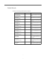
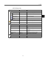
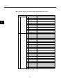
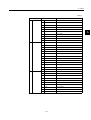
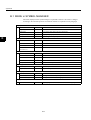
Related Manuals
Refer to the following related manuals as required.
Manual Name
Manual Number
Contents
MP900 Series Machine Controller
New Ladder Editor
Programming Manual
SIEZ-C887-13.1
Describes the programming instructions used in MP900 New Ladder
Editor.
MP900 Series Machine Controller
User's Manual:
Ladder Programming
SIEZ-C887-1.2
Describes the instructions used in
MP900 ladder logic programming.
MP900 Series Machine Controller
User's Manual:
Motion Programming
SIEZ-C887-1.3
Describes the motion programming
language used for MP900 Machine
Controllers.
MP900 Series Machine Controller
User's Manual:
MECHATROLINK
SIEZ-C887-5.1
Describes MECHATROLINK Modules used for MP900 Machine Controllers.
MP910 Machine Controller
User's Manual:
Design and Maintenance
SIEZ-C887-3.1
Describes the design and maintenance for the MP910 Machine Controller.
MP920 Machine Controller
User's Manual:
Design and Maintenance
SIEZ-C887-2.1
Describes the design and maintenance for the MP920 Machine Controller.
MP930 Machine Controller
User's Manual:
Design and Maintenance
SIEZ-C887-1.1
Describes the design and maintenance for the MP930 Machine Controller.
MP940 Machine Controller
User's Manual:
Design and Maintenance
SIEZ-C887-4.1
Describes the design and maintenance for the MP940 Machine Controller.
MP920 Machine Controller
User's Manual:
Motion Module
SIEZ-C887-2.5
Describes the functions, specifications, and usage of the MP920
Motion Modules (SVA-01, SVB-01,
and PO-01).
MP920 Machine Controller
User's Manual:
Communications Module
SIEZ-C887-2.6
Describes the functions, specifications, and usage of the MP920 Communications Modules (217IF, 215IF,
and 218IF).
MP920 Machine Controller
User's Manual:
DeviceNet
SIEZ-C887-5.2
Describes the functions, specifications, and operating methods of the
MP920 DeviceNet Module (260IF).
v
CONTENTS
1 BASIC OPERATION
1.1 CONFIGURATION - - - - - - - - - - - - - - - - - - - - - - - - - - - - - - 1-2
1.2 FILE MANAGER - - - - - - - - - - - - - - - - - - - - - - - - - - - - - - - 1-3
1.2.1 Folder Display - - - - - - - - - - - - - - - - - - - - - - - - - - - - - - - - - - - - - - - - 1-3
1.2.2 Program File Display - - - - - - - - - - - - - - - - - - - - - - - - - - - - - - - - - - - 1-3
1.3 CREATING NEW PROGRAM - - - - - - - - - - - - - - - - - - - - - - 1-5
1.3.1 Off-line Mode- - - - - - - - - - - - - - - - - - - - - - - - - - - - - - - - - - - - - - - - - 1-5
1.3.2 On-line Mode- - - - - - - - - - - - - - - - - - - - - - - - - - - - - - - - - - - - - - - - - 1-6
1.3.3 Create New Function - - - - - - - - - - - - - - - - - - - - - - - - - - - - - - - - - - - 1-8
1.4 OPEN A PROGRAM - - - - - - - - - - - - - - - - - - - - - - - - - - - 1-12
1.4.1 Open as New Window - - - - - - - - - - - - - - - - - - - - - - - - - - - - - - - - - 1-12
1.4.2 Open as New Sheet - - - - - - - - - - - - - - - - - - - - - - - - - - - - - - - - - - - 1-13
1.5 LADDER EDITOR VIEW - - - - - - - - - - - - - - - - - - - - - - - - - 1-16
1.5.1 Components of Ladder Editor - - - - - - - - - - - - - - - - - - - - - - - - - - - - 1-16
1.5.2 Select View - - - - - - - - - - - - - - - - - - - - - - - - - - - - - - - - - - - - - - - - - 1-17
1.6 TOOL BAR - - - - - - - - - - - - - - - - - - - - - - - - - - - - - - - - - - 1-22
1.6.1 Display Mode - - - - - - - - - - - - - - - - - - - - - - - - - - - - - - - - - - - - - - - 1-22
1.6.2 Tool Bar Function- - - - - - - - - - - - - - - - - - - - - - - - - - - - - - - - - - - - - 1-23
1.7 KEYBOARD OPERATION - - - - - - - - - - - - - - - - - - - - - - - 1-24
1.7.1 Keyboard Operations on a Rung - - - - - - - - - - - - - - - - - - - - - - - - - - 1-24
1.7.2 Shortcut Keys - - - - - - - - - - - - - - - - - - - - - - - - - - - - - - - - - - - - - - - 1-24
2 PROGRAMMING
2.1 PROGRAMMING - - - - - - - - - - - - - - - - - - - - - - - - - - - - - - - 2-3
2.1.1 Object- - - - - - - - - - - - - - - - - - - - - - - - - - - - - - - - - - - - - - - - - - - - - - 2-3
2.2 SELECT - - - - - - - - - - - - - - - - - - - - - - - - - - - - - - - - - - - - - 2-7
2.2.1
2.2.2
2.2.3
2.2.4
Select Object and Display- - - - - - - - - - - - - - - - - - - - - - - - - - - - - - - - 2-7
Cursor Operation - - - - - - - - - - - - - - - - - - - - - - - - - - - - - - - - - - - - - 2-11
Select Multiple Objects - - - - - - - - - - - - - - - - - - - - - - - - - - - - - - - - - 2-13
Range Selection with Mouse- - - - - - - - - - - - - - - - - - - - - - - - - - - - - 2-14
2.3 INSERT- - - - - - - - - - - - - - - - - - - - - - - - - - - - - - - - - - - - - 2-17
2.3.1
2.3.2
2.3.3
2.3.4
Insert Rung Comment - - - - - - - - - - - - - - - - - - - - - - - - - - - - - - - - Insert Rung - - - - - - - - - - - - - - - - - - - - - - - - - - - - - - - - - - - - - - - - Insert Instruction - - - - - - - - - - - - - - - - - - - - - - - - - - - - - - - - - - - - Insert Branch- - - - - - - - - - - - - - - - - - - - - - - - - - - - - - - - - - - - - - - -
2-17
2-18
2-20
2-24
2.4 DELETE - - - - - - - - - - - - - - - - - - - - - - - - - - - - - - - - - - - - 2-26
2.4.1
2.4.2
2.4.3
2.4.4
Delete Rung Comment - - - - - - - - - - - - - - - - - - - - - - - - - - - - - - - - Delete Rung - - - - - - - - - - - - - - - - - - - - - - - - - - - - - - - - - - - - - - - Delete Instruction- - - - - - - - - - - - - - - - - - - - - - - - - - - - - - - - - - - - Delete Branch - - - - - - - - - - - - - - - - - - - - - - - - - - - - - - - - - - - - - - vi
2-26
2-27
2-28
2-29
2.5 BRANCH OPERATION - - - - - - - - - - - - - - - - - - - - - - - - - - 2-30
2.5.1
2.5.2
2.5.3
2.5.4
Branch Operation Mode - - - - - - - - - - - - - - - - - - - - - - - - - - - - - - - - 2-30
Create Branch - - - - - - - - - - - - - - - - - - - - - - - - - - - - - - - - - - - - - - - 2-30
Edit Branch - - - - - - - - - - - - - - - - - - - - - - - - - - - - - - - - - - - - - - - - - 2-32
Delete Branch - - - - - - - - - - - - - - - - - - - - - - - - - - - - - - - - - - - - - - - 2-33
2.6 EDIT CHARACTER STRING- - - - - - - - - - - - - - - - - - - - - - 2-34
2.6.1 Edit Character String in the Program Comment - - - - - - - - - - - - - - - - 2-34
2.6.2 Edit Character String in the Rung Comment - - - - - - - - - - - - - - - - - - 2-35
2.6.3 Edit Character String in the Instruction - - - - - - - - - - - - - - - - - - - - - - 2-36
2.7 EDIT OBJECT - - - - - - - - - - - - - - - - - - - - - - - - - - - - - - - - 2-44
2.7.1
2.7.2
2.7.3
2.7.4
2.7.5
Edit Single Instruction - - - - - - - - - - - - - - - - - - - - - - - - - - - - - - - - - - 2-44
Edit Operand of Instruction - - - - - - - - - - - - - - - - - - - - - - - - - - - - - - 2-49
Edit Multiple Objects - - - - - - - - - - - - - - - - - - - - - - - - - - - - - - - - - - - 2-52
Undo - - - - - - - - - - - - - - - - - - - - - - - - - - - - - - - - - - - - - - - - - - - - - - 2-57
Redo - - - - - - - - - - - - - - - - - - - - - - - - - - - - - - - - - - - - - - - - - - - - - - 2-57
2.8 SAVE PROGRAM - - - - - - - - - - - - - - - - - - - - - - - - - - - - - 2-58
2.8.1 Save - - - - - - - - - - - - - - - - - - - - - - - - - - - - - - - - - - - - - - - - - - - - - - 2-58
2.8.2 Save All - - - - - - - - - - - - - - - - - - - - - - - - - - - - - - - - - - - - - - - - - - - - 2-59
2.9 VERIFY PROGRAM - - - - - - - - - - - - - - - - - - - - - - - - - - - - 2-60
2.9.1 Verify- - - - - - - - - - - - - - - - - - - - - - - - - - - - - - - - - - - - - - - - - - - - - - 2-60
2.9.2 Verify All Program- - - - - - - - - - - - - - - - - - - - - - - - - - - - - - - - - - - - - 2-62
3 DISPLAY
3.1 EDITOR OPTION DIALOG - - - - - - - - - - - - - - - - - - - - - - - - 3-2
3.1.1
3.1.2
3.1.3
3.1.4
3.1.5
3.1.6
Editor Option Dialog Configuration - - - - - - - - - - - - - - - - - - - - - - - - - -3-2
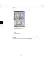
Color - - - - - - - - - - - - - - - - - - - - - - - - - - - - - - - - - - - - - - - - - - - - - - -3-2
Font - - - - - - - - - - - - - - - - - - - - - - - - - - - - - - - - - - - - - - - - - - - - - - -3-5
Ladder Display - - - - - - - - - - - - - - - - - - - - - - - - - - - - - - - - - - - - - - - -3-6
Control - - - - - - - - - - - - - - - - - - - - - - - - - - - - - - - - - - - - - - - - - - - - -3-9
Key - - - - - - - - - - - - - - - - - - - - - - - - - - - - - - - - - - - - - - - - - - - - - - - 3-10
3.2 ZOOM - - - - - - - - - - - - - - - - - - - - - - - - - - - - - - - - - - - - - - 3-11
3.3 INSTRUCTION PALETTE - - - - - - - - - - - - - - - - - - - - - - - - 3-12
3.3.1 Instruction Palette- - - - - - - - - - - - - - - - - - - - - - - - - - - - - - - - - - - - - 3-12
3.3.2 User Customized Tab - - - - - - - - - - - - - - - - - - - - - - - - - - - - - - - - - - 3-13
3.3.3 Quick View Property - - - - - - - - - - - - - - - - - - - - - - - - - - - - - - - - - - - 3-16
3.4 OUTPUT WINDOW - - - - - - - - - - - - - - - - - - - - - - - - - - - - 3-18
3.4.1 Output Window Display - - - - - - - - - - - - - - - - - - - - - - - - - - - - - - - - - 3-18
3.4.2 Detail of the Output Window - - - - - - - - - - - - - - - - - - - - - - - - - - - - - 3-19
3.5 TOOLBAR CUSTOMIZE DIALOG - - - - - - - - - - - - - - - - - - 3-20
3.5.1
3.5.2
3.5.3
3.5.4
3.5.5
3.5.6
3.5.7
Display and Configuration of Toolbar Customize Dialog - - - - - - - - - - 3-20
Commands - - - - - - - - - - - - - - - - - - - - - - - - - - - - - - - - - - - - - - - - - 3-20
Toolbars- - - - - - - - - - - - - - - - - - - - - - - - - - - - - - - - - - - - - - - - - - - - 3-21
Keyboard - - - - - - - - - - - - - - - - - - - - - - - - - - - - - - - - - - - - - - - - - - - 3-22
Other- - - - - - - - - - - - - - - - - - - - - - - - - - - - - - - - - - - - - - - - - - - - - - 3-23
Edit Icon Image - - - - - - - - - - - - - - - - - - - - - - - - - - - - - - - - - - - - - - 3-24
Customizing Operation - - - - - - - - - - - - - - - - - - - - - - - - - - - - - - - - - 3-28
vii
3.6 FUNCTION KEYS - - - - - - - - - - - - - - - - - - - - - - - - - - - - - 3-29
3.6.1 Function Bar - - - - - - - - - - - - - - - - - - - - - - - - - - - - - - - - - - - - - - - - 3-29
3.6.2 Function Key Assignment - - - - - - - - - - - - - - - - - - - - - - - - - - - - - - - 3-30
4 FIND/REPLACE
4.1 FIND - - - - - - - - - - - - - - - - - - - - - - - - - - - - - - - - - - - - - - - - 4-2
4.1.1 Find - - - - - - - - - - - - - - - - - - - - - - - - - - - - - - - - - - - - - - - - - - - - - - - 4-2
4.1.2 Find from Files- - - - - - - - - - - - - - - - - - - - - - - - - - - - - - - - - - - - - - - - 4-6
4.2 REPLACE - - - - - - - - - - - - - - - - - - - - - - - - - - - - - - - - - - - 4-10
4.3 CROSS REFERENCE - - - - - - - - - - - - - - - - - - - - - - - - - - 4-14
4.3.1 Display Cross Reference Window - - - - - - - - - - - - - - - - - - - - - - - - - 4-14
4.3.2 Cross Reference Condition - - - - - - - - - - - - - - - - - - - - - - - - - - - - - - 4-16
4.3.3 Output to File- - - - - - - - - - - - - - - - - - - - - - - - - - - - - - - - - - - - - - - - 4-18
5 SYMBOL DATABASE
5.1 SYMBOL MANAGER - - - - - - - - - - - - - - - - - - - - - - - - - - - - 5-2
5.1.1 Symbol Manager Menu - - - - - - - - - - - - - - - - - - - - - - - - - - - - - - - - - 5-2
5.1.2 Data Tree - - - - - - - - - - - - - - - - - - - - - - - - - - - - - - - - - - - - - - - - - - - 5-3
5.2 SYMBOL LIST - - - - - - - - - - - - - - - - - - - - - - - - - - - - - - - - - 5-4
5.2.1
5.2.2
5.2.3
5.2.4
5.2.5
5.2.6
5.2.7
Symbol List - - - - - - - - - - - - - - - - - - - - - - - - - - - - - - - - - - - - - - - - - - 5-4
Add Symbol- - - - - - - - - - - - - - - - - - - - - - - - - - - - - - - - - - - - - - - - - - 5-6
Insert Symbol - - - - - - - - - - - - - - - - - - - - - - - - - - - - - - - - - - - - - - - - 5-7
Delete Symbol - - - - - - - - - - - - - - - - - - - - - - - - - - - - - - - - - - - - - - - - 5-8
Import Symbol Data - - - - - - - - - - - - - - - - - - - - - - - - - - - - - - - - - - - - 5-9
Export Symbol Data - - - - - - - - - - - - - - - - - - - - - - - - - - - - - - - - - - - 5-10
Find/Replace - - - - - - - - - - - - - - - - - - - - - - - - - - - - - - - - - - - - - - - - 5-11
5.3 REGISTER MAP - - - - - - - - - - - - - - - - - - - - - - - - - - - - - - 5-16
5.3.1 Register Map- - - - - - - - - - - - - - - - - - - - - - - - - - - - - - - - - - - - - - - - 5-16
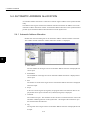
5.4 AUTOMATIC ADDRESS ALLOCATION - - - - - - - - - - - - - - 5-18
5.4.1 Automatic Address Allocation - - - - - - - - - - - - - - - - - - - - - - - - - - - - 5-18
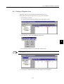
5.4.2 Setting of Register Area - - - - - - - - - - - - - - - - - - - - - - - - - - - - - - - - 5-19
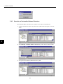
5.4.3 Execution of Automatic Address Allocation- - - - - - - - - - - - - - - - - - - 5-20
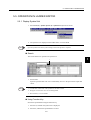
5.5 OPERATION IN LADDER EDITOR - - - - - - - - - - - - - - - - - 5-21
5.5.1 Display Symbol List - - - - - - - - - - - - - - - - - - - - - - - - - - - - - - - - - - - 5-21
5.5.2 Display Register Map - - - - - - - - - - - - - - - - - - - - - - - - - - - - - - - - - - 5-23
5.5.3 Unregistered Symbol List - - - - - - - - - - - - - - - - - - - - - - - - - - - - - - - 5-26
6 DEBUGGING
6.1 BASIC FUNCTION - - - - - - - - - - - - - - - - - - - - - - - - - - - - - - 6-2
6.1.1 Display Current Values - - - - - - - - - - - - - - - - - - - - - - - - - - - - - - - - - - 6-2
6.1.2 SYNC - - - - - - - - - - - - - - - - - - - - - - - - - - - - - - - - - - - - - - - - - - - - - - 6-3
6.1.3 HOLD (supported in the future) - - - - - - - - - - - - - - - - - - - - - - - - - - - - 6-4
viii
6.2 DISABLE COILS - - - - - - - - - - - - - - - - - - - - - - - - - - - - - - - 6-5
6.2.1
6.2.2
6.2.3
6.2.4
Display - - - - - - - - - - - - - - - - - - - - - - - - - - - - - - - - - - - - - - - - - - - - -6-5
Set Disable ON - - - - - - - - - - - - - - - - - - - - - - - - - - - - - - - - - - - - - - -6-6
Set Disable OFF- - - - - - - - - - - - - - - - - - - - - - - - - - - - - - - - - - - - - - -6-6
Cancel Disable - - - - - - - - - - - - - - - - - - - - - - - - - - - - - - - - - - - - - - - -6-7
6.3 REFER - - - - - - - - - - - - - - - - - - - - - - - - - - - - - - - - - - - - - - 6-8
6.3.1 Refer on the SEE Instruction - - - - - - - - - - - - - - - - - - - - - - - - - - - - - -6-8
6.3.2 Refer on the FUNC Instruction - - - - - - - - - - - - - - - - - - - - - - - - - - - - -6-9
6.4 QUICK REFERENCE - - - - - - - - - - - - - - - - - - - - - - - - - - - 6-10
6.4.1
6.4.2
6.4.3
6.4.4
Display - - - - - - - - - - - - - - - - - - - - - - - - - - - - - - - - - - - - - - - - - - - - 6-10
Register List Page - - - - - - - - - - - - - - - - - - - - - - - - - - - - - - - - - - - - 6-11
Watch Page - - - - - - - - - - - - - - - - - - - - - - - - - - - - - - - - - - - - - - - - - 6-14
The definition data is added from the ladder editor. - - - - - - - - - - - - - 6-17
6.5 CURRENT VALUE MONITOR - - - - - - - - - - - - - - - - - - - - - 6-18
6.5.1 Display of Current Value Monitor Window - - - - - - - - - - - - - - - - - - - - 6-18
6.5.2 Start and Stop Current Value Monitor - - - - - - - - - - - - - - - - - - - - - - - 6-21
6.5.3 Pop-up Menu - - - - - - - - - - - - - - - - - - - - - - - - - - - - - - - - - - - - - - - - 6-22
7 PRINTING
7.1 PRINT PREVIEW - - - - - - - - - - - - - - - - - - - - - - - - - - - - - - - 7-2
7.2 PRINTING - - - - - - - - - - - - - - - - - - - - - - - - - - - - - - - - - - - - 7-5
7.3 PAGE SETUP - - - - - - - - - - - - - - - - - - - - - - - - - - - - - - - - - 7-7
8 LADDER CONVERSION TOOL
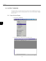
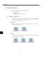
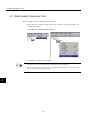
8.1 Start Ladder Conversion Tool- - - - - - - - - - - - - - - - - - - - - - - 8-2
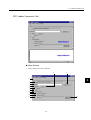
8.2 Ladder Conversion Tool - - - - - - - - - - - - - - - - - - - - - - - - - - 8-3
8.3 Menu- - - - - - - - - - - - - - - - - - - - - - - - - - - - - - - - - - - - - - - - 8-7
Appendix A
A.1 MENU- - - - - - - - - - - - - - - - - - - - - - - - - - - - - - - - - - - - - - - - 10
Appendix B
B.1 MENU in SYMBOL MANAGER - - - - - - - - - - - - - - - - - - - - - 20
ix
x
1
1
BASIC OPERATION
This section describes the basic operationof the ladder editor.
1.1 CONFIGURATION - - - - - - - - - - - - - - - - - - - - - - - - - - - - - - 1-2
1.2 FILE MANAGER - - - - - - - - - - - - - - - - - - - - - - - - - - - - - - - - 1-3
1.2.1 Folder Display - - - - - - - - - - - - - - - - - - - - - - - - - - - - - - - - - - - - - - - - 1-3
1.2.2 Program File Display - - - - - - - - - - - - - - - - - - - - - - - - - - - - - - - - - - - 1-3
1.3 CREATING NEW PROGRAM - - - - - - - - - - - - - - - - - - - - - - - 1-5
1.3.1 Off-line Mode - - - - - - - - - - - - - - - - - - - - - - - - - - - - - - - - - - - - - - - - 1-5
1.3.2 On-line Mode - - - - - - - - - - - - - - - - - - - - - - - - - - - - - - - - - - - - - - - - 1-6
1.3.3 Create New Function - - - - - - - - - - - - - - - - - - - - - - - - - - - - - - - - - - - 1-8
1.4 OPEN A PROGRAM - - - - - - - - - - - - - - - - - - - - - - - - - - - - 1-12
1.4.1 Open as New Window - - - - - - - - - - - - - - - - - - - - - - - - - - - - - - - - - 1-12
1.4.2 Open as New Sheet - - - - - - - - - - - - - - - - - - - - - - - - - - - - - - - - - - - 1-13
1.5 LADDER EDITOR VIEW - - - - - - - - - - - - - - - - - - - - - - - - - 1-16
1.5.1 Components of Ladder Editor - - - - - - - - - - - - - - - - - - - - - - - - - - - - 1-16
1.5.2 Select View - - - - - - - - - - - - - - - - - - - - - - - - - - - - - - - - - - - - - - - - - 1-17
1.6 TOOL BAR - - - - - - - - - - - - - - - - - - - - - - - - - - - - - - - - - - - 1-22
1.6.1 Display Mode - - - - - - - - - - - - - - - - - - - - - - - - - - - - - - - - - - - - - - - 1-22
1.6.2 Tool Bar Function - - - - - - - - - - - - - - - - - - - - - - - - - - - - - - - - - - - - - 1-23
1.7 KEYBOARD OPERATION - - - - - - - - - - - - - - - - - - - - - - - - 1-24
1.7.1 Keyboard Operations on a Rung - - - - - - - - - - - - - - - - - - - - - - - - - - 1-24
1.7.2 Shortcut Keys - - - - - - - - - - - - - - - - - - - - - - - - - - - - - - - - - - - - - - - 1-24
1-1
1 BASIC OPERATION
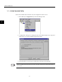
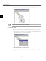
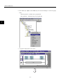
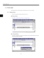
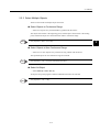
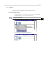
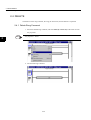
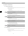
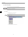
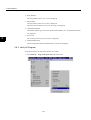
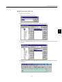
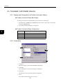
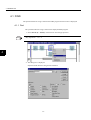
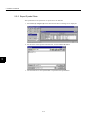
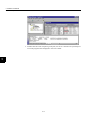
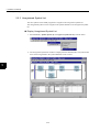
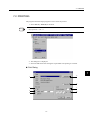
1.1 CONFIGURATION
When the new ladder editor method is used, the configuration needs to be set.
1. Select View (V) - Configuration (C) of the File Manager menu.
1
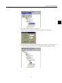
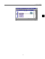
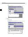
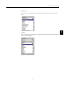
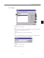
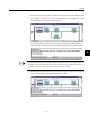
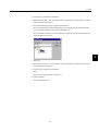
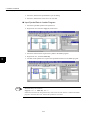
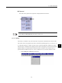
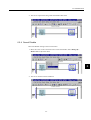
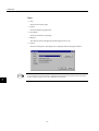
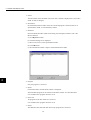
2. “Configuration” dialog box is displayed. Select the Ladder Program tab, and place a
check mark in “Use the new ladder program description”.
3. Click [OK] button. This setting is available after restarting the File Manager.
INFO
If the new ladder program description is selected, all folders created in the original Ladder editer are
not available.
1-2
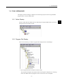
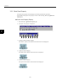
1.2 FILE MANAGER
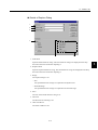
1.2 FILE MANAGER
The display of the file manager is different in the following respects from the original ladder
program editor to the new ladder editor.
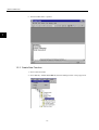
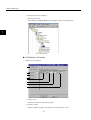
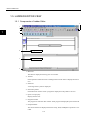
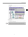
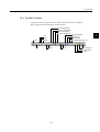
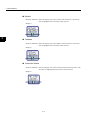
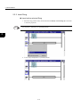
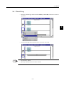
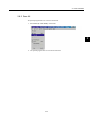
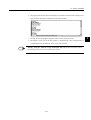
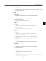
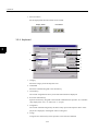
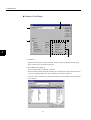
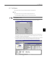
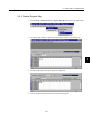
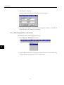
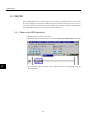
1.2.1 Folder Display
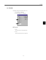
The PLC folder and CPU folder that were made using the original ladder editor are shown in
the figure below and cannot be used.
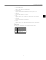
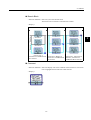
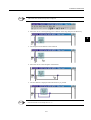
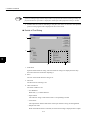
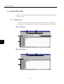
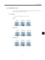
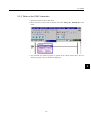
1.2.2 Program File Display
There are the following six kinds of program files displayed in the File Manager.
1. Not Compiled file that is available in off-line mode.
The program file displays the program without executing the compilation (or verifying).
In the new ladder editor, the program can be saved as a file even if compiled.
1-3
1
1 BASIC OPERATION
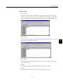
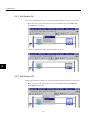
1.2.2 Program File Display
Refer to 2.9 Verifying Program.
2. Compiled File.
The program file displays the program already compiled.
3. Unmatched File
The program file displays the program that has be unmatched in some cases.
There are three cases that cause unmatched.
1
• Unmatched version number of data in the controller
• Unmatched version number of data between the controller and the hard disk on PC
• Unmatched CPU environment
When unmatched file is edited, possibility of the restoration of data and how to restore
data are displayed as a message.
4. Not Compiled and Disabled file that is available at off-line mode.
The program file displays the disabled program without executing the compilation (or
verifying). In a new ladder editor, the program can be saved as a file even if compiled.
5. Compiled and Disabled File.
The program file displays the disabled program already compiled.
6. Unmatched and Disabled File
The program file displays the disabled program that is unmatched in some cases.
IMPORTANT
INFO
It is necessary to adjust all files by loading or dumping CPU environment when programs are edited
connected with the controller at on-line mode.
Compile (verification) of the program file created by the Ladder editor of a new version (Ver.4.xx)
generates automatically the program file of the same from as the conventional version (Ver.3.xx).
This file should not edit by the conventional version. It becomes impossible to edit the file by the Ladder editor of a new Version, when this work is performed.
The following comment is inserted automatically in the program file of conventional form.
0000 "Ladder Compiler Version: 1.00"
0001 "[CAUTION}: Don't edit this file."
0002 "This program code is generated automatically."
0003 "If you edit this program, you can't it edit it on"
0004 "the any other editor."
1-4
1.3 CREATING NEW PROGRAM
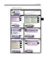
1.3 CREATING NEW PROGRAM
The programs can be created from every folder such as High Scan Programs at Program folder.
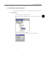
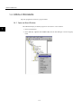
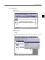
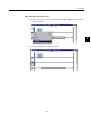
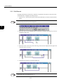
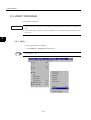
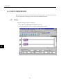
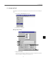
1.3.1 Off-line Mode
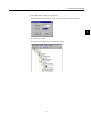
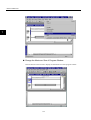
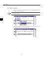
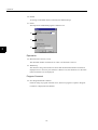
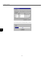
1. Select the folder suitable to the type of program.
2. Select File (F) - Create New DWG (N) from the File Manager menu or from the popup
menu.
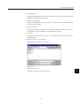
3. "Input DWG Name" dialog box is displayed.
Input the program name and select the type of program. Click [OK] button.
1-5
1
1 BASIC OPERATION
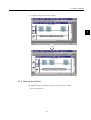
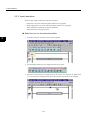
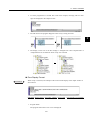
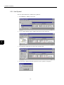
1.3.2 On-line Mode
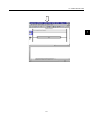
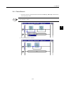
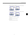
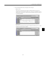
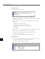
4. New program is created. New program is displayed in the File Manager window.
1
INFO
END instruction is prepared in a new program automatically.
1.3.2 On-line Mode
Make sure to log on the Controller to create programs or definition data for the controller.
1. Select the CPU folder or controller folder to be logged on. Select Log On (G) from File
(F) of the File Manager menu or from the popup menu.
2. Select the folder suitable to the kind of program.
3. Select File (F) - Create New DWG (N) of the File Manager menu or from the popup
menu.
1-6
1.3 CREATING NEW PROGRAM
1
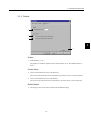
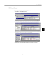
4. "Input DWG Name" dialog box is displayed.
Input the program name and select the type of program. Click [OK] button.
5. The new program is compiled and downloaded to the controller at the same time as it is
created. New program is displayed as a Compiled file in the File Manager window.
1-7
1 BASIC OPERATION
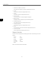
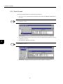
1.3.3 Create New Function
6. Then the ladder editor is opened.
1
1.3.3 Create New Function
1. Select a function folder.
2. Select File (F) - Create New DWG (N) from File Manager menu or the popup menu.
1-8
1.3 CREATING NEW PROGRAM
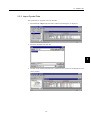
3. "Input DWG Name" dialog box is displayed.
Input the function name and select the "FUNC" in DWG Type, Click [OK] button.
1
4. New function is created.
New function is displayed in the File Manager window.
1-9
1 BASIC OPERATION
1.3.3 Create New Function
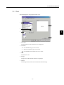
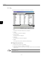
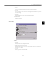
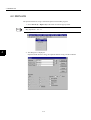
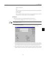
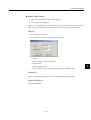
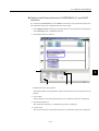
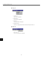
5. Define the I/O of New function.
Select a function file.
Select File (F) - Property (R) from File Manager menu or the popup menu.
1
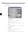
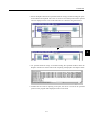
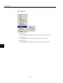
I/O Definition of Function
Define the I/O of function.
1
2
3
4
5
6
7
8
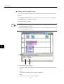
1. Verify on save
Function is verified on saving the property.
2. Number of Input
Input the number of inputs to the function, in the range from 1 to 16.
1-10
1.3 CREATING NEW PROGRAM
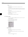
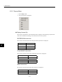
3. Number of address Input
Input 1 to input, and 0 not to input the address.
4. Number of output
Input the number of outputs to the function, in the range from 1 to 16.
5. Input type
Select the input data type for the function.
1
6. Input
Input the comment on the input data of the function with 8 or less characters.
7. Output type
Select the output data type for the function.
8. Output
Input the comment on the output data of the function with 8 or less characters.
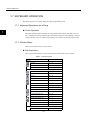
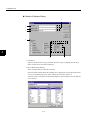
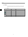
Data types
The data types to selected at step 5 and 7 are shown in the table below.
Item
Data type
B-VAL
Bit type
I-REG
Integer type
L-LEG
Double-length integer type
F-REG
Real-number type
1-11
1 BASIC OPERATION
1.4.1 Open as New Window
1.4 OPEN A PROGRAM
Open the program file in below a program folder.
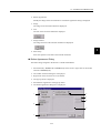
1.4.1 Open as New Window
1
The additional display of another program is carried out in a new window.
1. Select a program file.
2. Select File (F) - Open as new window (W) from the File Manager or from the popup
menu.
1-12
1.4 OPEN A PROGRAM
3. A program is displayed in a new window.
1
1.4.2 Open as New Sheet
The additional display of another program is carried out in a new Sheet.
1. Select a program file.
1-13
1 BASIC OPERATION
1.4.2 Open as New Sheet
2. Select File (F) - Open as new Sheet (A) from the File Manager or from the popup
menu.
<Mouse operation: > Double click a program file
<Key operation: > Push Enter key on a program file
1
3. A program is displayed in a new sheet.
1-14
1.4 OPEN A PROGRAM
1
1-15
1 BASIC OPERATION
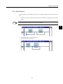
1.5.1 Components of Ladder Editor
1.5 LADDER EDITOR VIEW
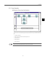
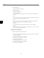
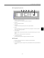
1.5.1 Components of Ladder Editor
5
1
2
1
4
6
Program Window
7
Output Window
3
1. Menu bar
The menu is displayed at the top part of a window.
2. Tool bar
Each operation of function such as editing function of the menu is displayed with an
icon.
3. Status bar
A message of the system is displayed.
4. Instruction palette
Each instruction used to create a program is displayed on the palette as an icon.
5. Quick view property
Display format is set.
6. Program window
The program is created on this window. Each program is displayed by the bottom tab.
7. Output Window
The result of them are displayed when the Verify, Find, and Replace operation is executed.
1-16
1.5 LADDER EDITOR VIEW
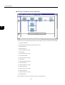
1.5.2 Select View
Bottom Tab
Select the tab in the program window, and selected program is displayed.
1
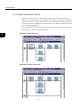
Multi-Window
Cascade
Select Window (W) - Cascade (D) to display the currently opened windows of one over the
other.
1-17
1 BASIC OPERATION
1.5.2 Select View
Next
Select Window (W) - Next (X) to change the active program window.
1
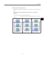
Tile
Tile Horizontally
Select Window (W) - Tile Horizontally (H) to display the currently opened windows of one
by one horizontally.
1-18
1.5 LADDER EDITOR VIEW
Tile Vertically
Select Window (W) - Tile Vertically (H) to display the currently opened windows of one by
one vertically.
1
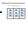
Change Focus
Select Window (W) - Change Focus (F) to change the active window such as program window, output window in the ladder editor.
INFO
This is different from Next function that changes the active program in the program window.
1-19
1 BASIC OPERATION
1.5.2 Select View
1
Change the Maximum Size of Program Window
Click the button on the title bar to display the maximum size of the program window.
1-20
1.5 LADDER EDITOR VIEW
1
1-21
1 BASIC OPERATION
1.6.1 Display Mode
1.6 TOOL BAR
The main menu in the window operation is displayed as an icon on the toolbar.
1.6.1 Display Mode
1
There are two kinds of display modes for the tool bar.
Docked Mode
The toolbar is docked within the frame on the ladder editor.
Undocked Mode
The toolbar is dragged to any place on the window. Its size is adjusted using the arrows displayed on both sides of the toolbar.
1-22
1.6 TOOL BAR
1.6.2 Tool Bar Function
When the mouse is located on the icon of the toolbar, its function is displayed.
Refer to appendix about the details of each function.
Normal Edit Mode
Branch Create Mode
Branch Edit Mode
Branch Delete Mode
Save
Print
Cut
Copy
Paste
Redo
Undo
1-23
Zoom
Find
Symbol Manager
Symbol List
Register Map
Unregistered Symbol List
Help
Print Manager
File Manager
Verify
1
1 BASIC OPERATION
1.7.1 Keyboard Operations on a Rung
1.7 KEYBOARD OPERATION
Keyboard operations are used to make the ladder programming easier.
1.7.1 Keyboard Operations on a Rung
1
Cursor Operation
Movement in the program comment, the rung, and between rungs is done with the arrow
keys. Jumping to the first program rung is executed by Home key, and jumping to the end
rung by End key. Use Ctrl + Home key to jump to the comment in the first program rung.
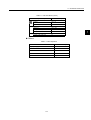
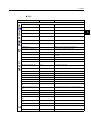
1.7.2 Shortcut Keys
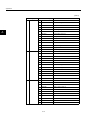
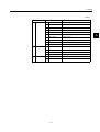
The list of the shortcut keys is shown below.
Pull-down Menu
The list of the shortcut keys as well as the pull-down menu items is shown below.
Table 1.1 Pull-down Menu
Menu (Function)
File (F)
Save (S)
Shortcut Key
Ctrl + S
Print (P)
Ctrl + P
Exit (N)
Edit (E)
Undo (U)
Alt + F4
Redo (R)
Ctrl + Y
Cut (T)
Ctrl + X
Copy (C)
Ctrl + C
Paste (P)
Ctrl + V
Delete (D)
Delete
Insert (I)
Add with Branch (A)
Insert Rung (I)
Insert
Ctrl + Insert
Insert
Insert Rung Comment (U)
Shift + Insert
Normal Edit Mode (N)
Ctrl + U
Insert Branch (B)
Branch Insert Mode (B)
Ctrl + B
Ctrl + I
Branch Edit Mode (E)
Ctrl + E
Ctrl + Z
Select All (L)
Verify File (V)
View (V)
Editor Options…(E)
Ctrl + A
F8
Alt + Enter
1-24
1.7 KEYBOARD OPERATION
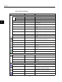
Table 1.1 Pull-down Menu (cont’d)
Menu (Function)
Search (S)
Find (F)
Shortcut Key
Ctrl + F
Replace (P)
Window (W)
Close (C)
Change Focus (F)
Next (X)
Help (H)
Ladder works Help (H)
Ctrl + H
Ctrl + F4
Ctrl + F7
Ctrl + F6
1
F1
Others
Table 1.2 Other Operation
Function
Shortcut Key
Display the popup menu
Shift + F10
Cancel
ESC
Menu bar mode control
Alt
Enter
Enter
Input of null character in text
Space
1-25
1 BASIC OPERATION
1.7.2 Shortcut Keys
1
1-26
2
PROGRAMMING
This section explains how to edit a program.
2.1 PROGRAMMING - - - - - - - - - - - - - - - - - - - - - - - - - - - - - - - 2-3
2.1.1 Object - - - - - - - - - - - - - - - - - - - - - - - - - - - - - - - - - - - - - - - - - - - - - - 2-3
2.2 SELECT - - - - - - - - - - - - - - - - - - - - - - - - - - - - - - - - - - - - - - 2-7
2.2.1 Select Object and Display - - - - - - - - - - - - - - - - - - - - - - - - - - - - - - - - 2-7
2.2.2 Cursor Operation - - - - - - - - - - - - - - - - - - - - - - - - - - - - - - - - - - - - - 2-11
2.2.3 Select Multiple Objects - - - - - - - - - - - - - - - - - - - - - - - - - - - - - - - - - 2-13
2.2.4 Range Selection with Mouse - - - - - - - - - - - - - - - - - - - - - - - - - - - - - 2-14
2.3 INSERT - - - - - - - - - - - - - - - - - - - - - - - - - - - - - - - - - - - - - 2-17
2.3.1 Insert Rung Comment - - - - - - - - - - - - - - - - - - - - - - - - - - - - - - - - 2.3.2 Insert Rung - - - - - - - - - - - - - - - - - - - - - - - - - - - - - - - - - - - - - - - - 2.3.3 Insert Instruction - - - - - - - - - - - - - - - - - - - - - - - - - - - - - - - - - - - - 2.3.4 Insert Branch - - - - - - - - - - - - - - - - - - - - - - - - - - - - - - - - - - - - - - - -
2-17
2-18
2-20
2-24
2.4 DELETE - - - - - - - - - - - - - - - - - - - - - - - - - - - - - - - - - - - - - 2-26
2.4.1 Delete Rung Comment - - - - - - - - - - - - - - - - - - - - - - - - - - - - - - - - 2.4.2 Delete Rung - - - - - - - - - - - - - - - - - - - - - - - - - - - - - - - - - - - - - - - 2.4.3 Delete Instruction - - - - - - - - - - - - - - - - - - - - - - - - - - - - - - - - - - - - 2.4.4 Delete Branch - - - - - - - - - - - - - - - - - - - - - - - - - - - - - - - - - - - - - - -
2-26
2-27
2-28
2-29
2.5 BRANCH OPERATION - - - - - - - - - - - - - - - - - - - - - - - - - - 2-30
2.5.1 Branch Operation Mode - - - - - - - - - - - - - - - - - - - - - - - - - - - - - - - 2.5.2 Create Branch - - - - - - - - - - - - - - - - - - - - - - - - - - - - - - - - - - - - - - 2.5.3 Edit Branch - - - - - - - - - - - - - - - - - - - - - - - - - - - - - - - - - - - - - - - - 2.5.4 Delete Branch - - - - - - - - - - - - - - - - - - - - - - - - - - - - - - - - - - - - - - -
2-30
2-30
2-32
2-33
2.6 EDIT CHARACTER STRING - - - - - - - - - - - - - - - - - - - - - - 2-34
2.6.1 Edit Character String in the Program Comment - - - - - - - - - - - - - - - 2-34
2.6.2 Edit Character String in the Rung Comment - - - - - - - - - - - - - - - - - - 2-35
2.6.3 Edit Character String in the Instruction - - - - - - - - - - - - - - - - - - - - - - 2-36
2-1
2
2 PROGRAMMING
2.7 EDIT OBJECT - - - - - - - - - - - - - - - - - - - - - - - - - - - - - - - - 2-44
2.7.1 Edit Single Instruction - - - - - - - - - - - - - - - - - - - - - - - - - - - - - - - - - -2-44
2.7.2 Edit Operand of Instruction - - - - - - - - - - - - - - - - - - - - - - - - - - - - - -2-49
2.7.3 Edit Multiple Objects - - - - - - - - - - - - - - - - - - - - - - - - - - - - - - - - - - -2-52
2.7.4 Undo - - - - - - - - - - - - - - - - - - - - - - - - - - - - - - - - - - - - - - - - - - - - - -2-57
2.7.5 Redo - - - - - - - - - - - - - - - - - - - - - - - - - - - - - - - - - - - - - - - - - - - - - -2-57
2.8 SAVE PROGRAM - - - - - - - - - - - - - - - - - - - - - - - - - - - - - - 2-58
2.8.1 Save - - - - - - - - - - - - - - - - - - - - - - - - - - - - - - - - - - - - - - - - - - - - - -2-58
2.8.2 Save All - - - - - - - - - - - - - - - - - - - - - - - - - - - - - - - - - - - - - - - - - - - -2-59
2.9 VERIFY PROGRAM - - - - - - - - - - - - - - - - - - - - - - - - - - - - 2-60
2
2.9.1 Verify - - - - - - - - - - - - - - - - - - - - - - - - - - - - - - - - - - - - - - - - - - - - - -2-60
2.9.2 Verify All Program - - - - - - - - - - - - - - - - - - - - - - - - - - - - - - - - - - - - -2-62
2-2
2.1 PROGRAMMING
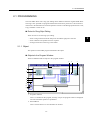
2.1 PROGRAMMING
This new ladder editor uses a rung style editing that is difference from the original ladder editor.
The rung is first specified in a program and then the instruction is placed on it. The location of
instruction or the destination of a branch operation is shown so the editing operation such as Cut,
Copy, and Paste is easier to use.
Rules for Rung Style Editing
There are rules to use the rung style editing.
2
• Insert a rung connected with the left power rail and the right power rail first.
• Insert a branch if the parallel circuit is required.
• Arrange instruction on the rung or the branch.
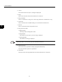
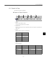
2.1.1 Object
The operation in the ladder program is defined as the object.
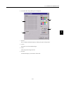
Objects In the Program Window
There are different kinds of objects in the program window.
1
2
3
4
5
6
7
10
8
a)
b)
c)
9
1. Program Comment
This is a comment for the program, and only one per one program window is displayed.
The Cut and Delete operation is prohibited.
2. Branch Block
This is a block that two or more branches are located.
2-3
2 PROGRAMMING
2.1.1 Object
3. Cursor
The location where the object is arranged is displayed.
4. Rung
This is basic line that instruction and branch are located on.
5. Rung Comment
This is a comment for a rung. One or more rung comments is available for a rung.
6. Instruction
This is instruction for the ladder editing. It is classified into another kind.
7. Branch
2
This is a branch that shows the parallel circuit.
8. Rung Left Power Rail
a) Rung Number
The rung number is displayed in order.
b) Step Number
The number of total steps to previous rung is displayed.
c) Nesting Number
The number of nesting is displayed.
INFO
The nesting number is increased using IF, FOR, and WHILE instruction.
9. END instruction
This instruction is prepared at creating a program automatically.
The Cut and Delete operation is prohibited.
10. Edit Mark
This mark shows the rung edited after the normal termination of verification.
2-4
2.1 PROGRAMMING
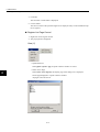
Details of Instructions
Relay Type
1
2
3
4
Function Block Type
Arithmetic Block Type
1
4
1
4
2
3
2
3
2
3
2
3
2
3
Display at Scope OFF
1
Display at Scope OFF
1
5
4
5
4
Program Control Type IF WHILE
Program Control Type EXPRESSION
1
4
1
4
6
7
Display at Scope OFF
Display at Scope OFF
5
5
1
4
1
4
Instruction including a text in a operand
[Table Instruction]
User Function FUNC
1
4
1
4
8
2
3
2
3
9
2
3
2
3
Display at Scope OFF
Display at Scope OFF
1
1
4
4
2-5
2
3
2
2 PROGRAMMING
2.1.1 Object
1. Comment for a address or instruction
The comment for a address or instruction is displayed and can be set.
2. Symbol
The symbol of instruction is displayed and can be set.
3. Address
The address of register is displayed and can be set.
4. Instruction Name
The instruction name or instruction diagram is displayed.
2
5. Button for Scope
The display format is changed by scope ON and OFF operation
6. Conditional Expression
The conditional expression is displayed and can be set.
7. Arithmetic Expression
The arithmetic expression is displayed and can be set.
8. String
The specified string such as the table name is displayed and can be set.
9. User Function Name
The user function name is displayed and can be set.
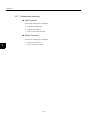
Category of Instruction
The main instruction displayed in the ladder program window is the following eleven classifications.
• RELAY
• DDC
• MATH
• TABLE
• LOGIC
• SYSTEM
• CONTROL
• SFC
• FUNCTION
• MOTION
• MOVE
Refer to the instruction manual for full details.
2-6
2.2 SELECT
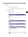
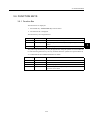
2.2 SELECT
There are two kinds of way to select the objects.
• Click the specified location using the mouse.
• Select the specified location by moving the cursor in the program with the arrow keys.
The selected object is highlighted with a specified color line (The default color is blue).
2.2.1 Select Object and Display
2
Program Comment
<Selection Method>: Select the display area of a program comment.
<Display>
Rung Comment
< Selection Method >: There are three kinds of selection as follows.
<Display>
Out of the Left Power Rail
Display Area
Comment Input Mode
Rung
< Selection Method >: Select the rung number.
< Display >
2-7
2 PROGRAMMING
2.2.1 Select Object and Display
Instruction
< Selection Method >: Select the display area of the instruction name of the instruction. The
instruction is highlighted with a blue line when selected.
< Display >
2
Branch
< Selection Method >: Select the junction of the branch.
The instruction on a branch is selected and a branch is not selected.
< Display >
Case 1
Case 2
Case 3
Instruction-1
Instruction-2
Instruction-3
Instruction-1 is selected.
Instruction-2 is selected.
2-8
Instruction-3 is selected.
2.2 SELECT
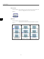
Branch Block
< Selection Method >: Select the joint of the branch block.
The instruction on a branch is selected with a branch.
< Display >
Branch-A
Instruction-1
Branch-B
Case 1
Instruction-2
Case 2
Case 3
2
Instruction-3
Instruction-3 and Branch-B
are selected.
Instruction-2, Branch-A,
Instruction-3 and Branch-B
are selected.
Instruction-1, Instruction-2,
Branch-A, Instruction-3
and Branch-B are selected.
Comment
< Selection Method >: Select the display area of the comment of the instruction. The instruction is highlighted with a blue line when selected.
< Display >
2-9
2 PROGRAMMING
2.2.1 Select Object and Display
Symbol
< Selection Method >: Select the display area of the symbol of the instruction. The instruction is highlighted with a blue line when selected.
< Display >
2
Address
< Selection Method >: Select the display area of the address of the instruction. The instruction is highlighted with a blue line when selected.
< Display >
Instruction Name
< Selection Method >: Select the display area of the instruction name of the instruction. The
instruction is highlighted with a blue line when selected.
< Display >
2-10
2.2 SELECT
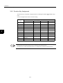
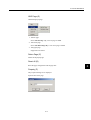
2.2.2 Cursor Operation
Example of Down Arrow Key Operation
1
2
3
2
4
5
The cursor moves in the following order when the down arrow key is selected in this example.
1. Program comment
2. Rung comment located out of the left power rail
3. Rung number 0
4. Rung number 1
:
5. Rung number n
INFO
The cursor moves in the opposite direction, if up arrow key is selected.
2-11
2 PROGRAMMING
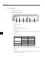
2.2.2 Cursor Operation
Example of Right Arrow Key Operation
4
1
3
2
5
8
6
7
12
9
10
11
15
13
14
17
16
2
18
The cursor moves in the following order when the right arrow key is selected in this example.
1. Program comment
2. Rung comment located out of the left power rail
3. Rung comment
4. Rung number 0
5. Insert location on a rung
6. Instruction
7. Insert location on a rung
8. Junction of branch
9. Insert location on a rung
10. Instruction
11. Branch Block Instruction
12. Joint of branch
13. Insert location on a rung
14. Other instruction
15. Insert location on a rung
16. Other instruction
17. Insert location on a rung
18. Rung number 1
Select the down arrow key, if the cursor moves to the under at 8.
2-12
2.2 SELECT
2.2.3 Select Multiple Objects
There are three kinds of multiple object selections.
Select Objects in Continuous Range
• Select two objects away with the Shift key pushed with the mouse.
The object selected first is the beginning point, and the object selected next is the ending
point, and then all object are selected between them in continuous range.
INFO
<Key Operation>: Shift + Arrow Key
Select Objects in Non-Continuous Range
• Select two or more objects away with the Ctrl key pushed with the mouse.
The specified objects in non-continuous range are selected.
INFO
<Key Operation>: Ctrl + Arrow Key (decided by Enter Key)
Select All Object
• Select Edit (E) - Select ALL (L).
All objects except the program comment and END instruction are selected.
INFO
<Key Operation>: Ctrl + A Key
2-13
2
2 PROGRAMMING
2.2.4 Range Selection with Mouse
2.2.4 Range Selection with Mouse
Multiple consecutive objects can be selected by enclosing the objects with mouse’s drug.
Move the mouse with the mouse button pushed from the starting point within the range of the
selection, a dotted line rectangle which shows the range of the selection is displayed, and the
selected objects are changed into blue. (The instruction is surrounded with a blue line and the
line of a branch changes blue)
The rectangle disappears when the mouse button is released in the terminal within the range
of the selection, and the selection operation ends.
2
Single Object Selection
Multiple Objects Selection
2-14
2.2 SELECT
Precantions At Range Selection
In range selection of the object containing a branch with a mouse, be careful of the following
points.
A Branch is not selected although the instruction on a branch is
selected.
< Selection Method >: Select the junction of the branch.
The instruction on a branch is selected and a branch is not selected.
< Display >
Case 1
Case 2
Case 3
Instruction-1
Instruction-2
Instruction-3
Instruction-1 is selected.
Instruction-2 is selected.
2-15
Instruction-3 is selected.
2
2 PROGRAMMING
2.2.4 Range Selection with Mouse
A Branch and the instruction on a branch are selected.
< Selection Method >: Select the joint of the branch block.
The instruction on a branch is selected with a branch.
< Display >
Branch-A
2
Instruction-1
Branch-B
Case 1
Instruction-2
Case 2
Case 3
Instruction-3
Instruction-3 and Branch-B
are selected.
Instruction-2, Branch-A,
Instruction-3 and Branch-B
are selected.
2-16
Instruction-1, Instruction-2,
Branch-A, Instruction-3 and
Branch-B are selected.
2.3 INSERT
2.3 INSERT
The Insertion of the rung comment, rung, instruction, and branch is explained.
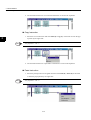
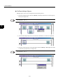
2.3.1 Insert Rung Comment
1. Select the rung number where the rung comment is newly inserted, and select Edit (E) Insert Rung Comment (U) of the menu or from the pop menu.
INFO
<Key Operation>: Shift + Insert
2. A new rung comment is displayed at a specified position.
2-17
2
2 PROGRAMMING
2.3.2 Insert Rung
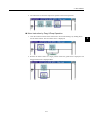
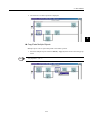
2.3.2 Insert Rung
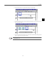
Insert before selected Rung
1. Select the rung position newly inserted and select Edit (E) - Insert Rung (I) of the menu
or from the pop menu.
INFO
<Key Operation>: Insert key at a specified position.
2
2. A new rung is displayed at a specified position.
2-18
2.3 INSERT
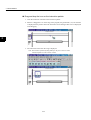
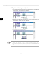
Insert after selected Rung
1. Select the rung position newly inserted and select Edit (E) - Add Rung (A) of the menu
or from the pop menu.
2
2. A new rung is displayed at a specified position.
2-19
2 PROGRAMMING
2.3.3 Insert Instruction
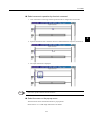
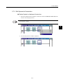
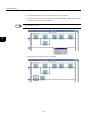
2.3.3 Insert Instruction
There are four kinds of instruction selection as follows.
• Select the icon on the instruction palette and insert it to program
• Drag and drop the icon on the instruction palette and insert it to program
• Select Mnemonic Operation by shortcut command
• Select the menu or the pop-up menu
Select the icon on the instruction palette
2
1. Click the instruction inserted on the instruction palette.
2. The selected instruction icon is displayed in the active status.
3. When the mouse pointer is brought close on the rung in the program, the guide mark
("V") for insertion is displayed at the position where the instruction can be arranged.
2-20
2.3 INSERT
4. The selected instruction is inserted when clicking at the guide mark.
2
5. The same instruction can be inserted continuously during the icon on the instruction palette is in the active status.
6. The icon on the instruction palette in the active status is turned off by clicking the icon
again, or right-click in the program window.
INFO
<Key Operation>: Esc
2-21
2 PROGRAMMING
2.3.3 Insert Instruction
Drag and drop the icon on the instruction palette
1. Click the instruction inserted on the instruction palette.
2. When it is dragged as it is on the rung in the program, the guide mark ("V") for insertion
is displayed at the position where the instruction can be arranged. The cursor is displayed
in the dragging.
2
3. The instruction inserted on the rung is displayed.
Note: The insertion operation by Drag & Drop is only once. The icon on the
instruction palette is in the non-active status.
2-22
2.3 INSERT
Select mnemonic operation by shortcut command
1. Click somewhere on the rung and the operation mode is changed into insert mode.
2
2. Input the mnemonic that is called as shortcut command from the keyboard, and enter it.
3. The input instruction is displayed.
INFO
Refer to the operation manual about the mnemonic.
Select the menu or the pop-up menu
The instruction can be inserted from menu or pop-up menu.
Please refer to 2.7.1 "Edit Single Instruction" for details.
2-23
2 PROGRAMMING
2.3.4 Insert Branch
2.3.4 Insert Branch
1. Select Edit (E) - Branch Insert Mode (B) of the menu or Click the Branch Insert Mode
button on the toolbar.
INFO
<Key Operation>: Ctrl + I
2
2. When the mouse pointer is brought close on the rung in the program, the guide mark
("V" mark) for insertion is displayed at the position where the branch can be inserted on
the rung and the cursor is changed into the branch insert mode.
3. Select the guide mark ("V" mark) as the beginning point and move the cursor to the right
direction on the rung. The guide mark ("V" mark) is displayed at the position as the ending point.
4. Click the guide mark and complete to insert the branch on the rung.
5. Click the following insertion beginning position when the branch is continuously
inserted. It is possible to insert branch continuously during the insert mode is selected.
2-24
2.3 INSERT
6. It is possible to turn off the branch insert mode by clicking the icon on the toolbar or by
right-click on the branch.
INFO
<Key Operation>: Esc
2
2-25
2 PROGRAMMING
2.4.1 Delete Rung Comment
2.4 DELETE
The deletion of the rung comment, the rung, the instruction, and the branch is explained.
2.4.1 Delete Rung Comment
1. Select the deleted rung comment, and select Edit (E) - Delete (D) of the menu or from
the pop menu.
2
INFO
<Key Operation>: Delete
2. The selected rung is deleted.
2-26
2.4 DELETE
2.4.2 Delete Rung
1. Select the deleted rung number and select Edit (E) - Delete (D) of the menu or from the
pop menu.
2
2. The selected rung is deleted and the cursor is moved to next rung.
INFO
1. <Key Operation>: Delete
2. The rung for the END instruction cannot be deleted.
2-27
2 PROGRAMMING
2.4.3 Delete Instruction
2.4.3 Delete Instruction
1. Select the instruction name of the deleted instruction, and select Edit (E) - Delete (D) of
the menu or from the pop-up menu.
INFO
<Key Operation>: Delete
2
2. The instruction is deleted and the object on the right side becomes selected. If there is no
instruction on the rung, the cursor is displayed there.
2-28
2.4 DELETE
2.4.4 Delete Branch
1. Select the junction of the deleted branch and select Edit (E) - Delete (D) of the menu or
from the pop-up menu.
INFO
<Key Operation>: Delete
2
2. The selected branch is deleted.
2-29
2 PROGRAMMING
2.5.1 Branch Operation Mode
2.5 BRANCH OPERATION
2.5.1 Branch Operation Mode
Change the edit mode from a normal edit mode to the branch operation modes. There are four
kinds of the edit mode as follows.
• Normal Edit Mode
It is the default mode.
The insert, delete, and edit of the instruction in the program are available.
2
<Key Operation >: Ctrl + U from other modes
INFO
• Branch Create Mode
It is the mode to create a branch in the program.
The new branch is created for the selected guide mark position
.
INFO
<Key Operation >: Ctrl + I from other modes
• Branch Edit Mode
It is the mode to edit a branch in the program.
The junction or the joint of the selected branch is changed to the other position.
INFO
<Key Operation >: Ctrl + E from other modes
• Branch Delete Mode (Supported in the future)
It is the mode to delete a branch in the program.
All instructions on the branch are deleted together.
INFO
<Key Operation >: Ctrl + D from other modes
2.5.2 Create Branch
The creating a new branch by shortcut key operation is explained. Please refer to 2.3.4 Insert
Branch about the mouse operation.
1. Input the Ctrl + I from the keyboard. The branch insert mode icon on the toolbar
becomes active.
2-30
2.5 BRANCH OPERATION
INFO
The branch insert mode mouse pointer is displayed.
2. Move the cursor to the beginning point of branch on the rung and press the Enter key.
2
3. The end point of the branch is then selected.
4. Move the cursor to the end point of the branch.
5. The new branch is displayed when the Enter key is pressed.
INFO
Normal edit mode is selected by the Ctrl + U.
2-31
2 PROGRAMMING
2.5.3 Edit Branch
2.5.3 Edit Branch
Changing the branch by shortcut key operation is explained. The junction or the joint of the
selected branch is changed to the other position.
1. Input the Ctrl + E from the keyboard. The branch edit mode icon on the toolbar becomes
active.
INFO
The branch edit mode mouse pointer is displayed.
2
2. Move the cursor to the changed point on the branch, and press the Enter key. It can be
changed to other point.
3. Move the cursor to the new point on the rung. The branch is displayed in the light color
while the cursor is moving.
4. Decide the new point by pressing the Enter key.
INFO
Normal edit mode is selected by the Ctrl + U.
2-32
2.5 BRANCH OPERATION
2.5.4 Delete Branch
Deleting a branch is explained. Please refer to 2.4.4 "Delete Branch" about the mouse operation.
1. Select the branch to be deleted with the mouse. The branch is changed into the selection
mode.
INFO
The toolbar and the shortcut key operation are not prepared now.
2
2. Input the Delete key from the keyboard.
3. The selected branch is deleted.
2-33
2 PROGRAMMING
2.6.1 Edit Character String in the Program Comment
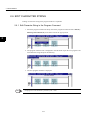
2.6 EDIT CHARACTER STRING
Editing of a character string in the program window is explained.
2.6.1 Edit Character String in the Program Comment
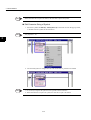
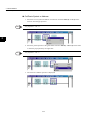
1. Select the program comment at the top area of the program window and select Edit (E) Edit Program Comment (G) of the menu or from the pop-up menu.
2
2. The program comment area is displayed in the edit mode. Input the new program comment character string and press the Enter key.
3. The new program comment is displayed.
INFO
Changing lines in the edit mode is possible by Ctrl + Enter.
2-34
2.6 EDIT CHARACTER STRING
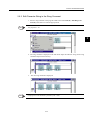
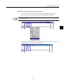
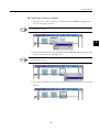
2.6.2 Edit Character String in the Rung Comment
1. Select a rung comment in the program window and select Edit (E) - Edit Rung Comment (E) of the menu or from the pop-up menu.
INFO
<Key Operation>: F2
2
2. The rung comment is displayed in the edit mode. Input the character string for the rung
comment and press the Enter key.
3. The new rung comment is displayed.
INFO
Changing lines in the edit mode is possible by Ctrl + Enter.
2-35
2 PROGRAMMING
2.6.3 Edit Character String in the Instruction
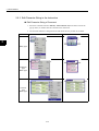
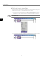
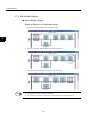
2.6.3 Edit Character String in the Instruction
Edit Character String of Comment
1. Select the comment and select Edit (E) - Edit Comment (O) of the menu or from the
pop-up menu, or double-click the comment in the instruction.
2. The selected comment is changed into the edit mode and it is possible to be edited.
Menu
2
Relay Type
Arithmetic
Type
Block Type
Function
Type
Block Type
2-36
Edit Mode
2.6 EDIT CHARACTER STRING
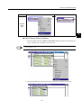
Menu
Edit Mode
Program
Control
Type
2
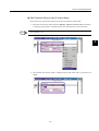
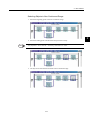
Edit Character String of Address
1. Select the address and select Edit (E) - Edit Address (E) of the menu or from the pop-up
menu, or double-click the address in the instruction.
INFO
<Key Operation>: F2
2. The selected address is changed into the edit mode and it is possible to be edited.
2-37
2 PROGRAMMING
2.6.3 Edit Character String in the Instruction
INFO
When immediate data is input to the address, the same data is input to the symbol.
Edit Character String of Symbol
1. Select the symbol and Edit (E) - Edit Symbol (S) of the menu or from the pop-up menu,
or double-click the symbol in the instruction.
INFO
<Key Operation>: F2
2
2. The selected symbol is changed into the edit mode and it is possible to be edited.
INFO
1. It is necessary to register the symbol for new registration of the instruction.
2. When immediate data is input to the symbol, the same data is input to the address.
2-38
2.6 EDIT CHARACTER STRING
Edit Character String of Instruction Name
1. Select the instruction name and select Edit (E) - Edit Instruction (N) of the menu or
from the pop-up menu, or double-click the instruction name in the instruction.
INFO
<Key Operation>: F2
2
2. The selected instruction name is changed into the edit mode and it is possible to be
edited. Input the instruction name by mnemonic key.
2-39
2 PROGRAMMING
2.6.3 Edit Character String in the Instruction
Edit Peculiar Character String of Object
In the operand of the instruction, there is something that contains the character string such as
TABLE instruction besides the symbol, the address, and the comment.
1. Select the peculiar character string and select Edit (E) - Edit String (E) of the menu or
from the pop-up menu, or double-click the peculiar character string in the instruction.
INFO
<Key Operation>: F2
2
2. The selected character string is changed into the edit mode, and it is possible to be edited.
2-40
2.6 EDIT CHARACTER STRING
Edit Character String of User Function Name
FUNC that is the user function instruction has the user function name as data.
1. Select the user function name and select Edit (E) - Edit User Function (E) of the menu
or from the pop-up menu, or double-click the user function name in the instruction.
INFO
<Key Operation>: F2
2
2. The selected user function name is changed into the edit mode, and it is possible to be
edited.
2-41
2 PROGRAMMING
2.6.3 Edit Character String in the Instruction
Edit Character String of Conditional Expression
As for IF and the WHILE instruction, the operand contains the conditional expression.
1. Select the operational expression and select Edit (E) - Edit Conditional Expression (E)
of the menu or from the pop-up menu, or double-click the conditional expression in the
instruction.
INFO
<Key Operation>: F2
2
2. The conditional expression by which the result of a Boolean type is output can be
described only by one line.
2-42
2.6 EDIT CHARACTER STRING
Edit Character String of Operational Expression
As for the EXPRESSION instruction, the operand contains the operational expression.
1. Select the EXPRESSION instruction and select Edit (E) - Edit Operational (E) of the
menu or from the pop-up menu, or double-click the operational expression in the instruction or double-click the operational expression in the instruction.
INFO
<Key Operation>: F2
2
2. The description by C language becomes possible.
Changing line in the arithmetic expression area is possible by Ctrl + Enter.
2-43
2 PROGRAMMING
2.7.1 Edit Single Instruction
2.7 EDIT OBJECT
2.7.1 Edit Single Instruction
Insert Instruction
1. Select the guide mark on the rung and select Edit (E) - Insert (I) of the menu or from the
pop-up menu by the right-click.
INFO
<Key Operation>: Insert
2
• From the pop-up menu of instruction
• From the pop-up menu between objects
2. The selected instruction is inserted.
2-44
2.7 EDIT OBJECT
Delete Instruction
1. Select the deleted instruction and select Edit (E) - Delete (D) of the menu or from the
pop-up menu by the right-click.
INFO
<Key Operation>: Delete
2
2. The selected instruction is deleted.
Cut Instruction
1. Select the cut out instruction and select Edit (E) - Cut (T) of the menu or from the popup menu by the right-click.
INFO
<Key Operation>: Ctrl + X
2-45
2 PROGRAMMING
2.7.1 Edit Single Instruction
2. The selected instruction is cut out and its information is saved in the clipboard.
Copy Instruction
1. Select the cut out instruction and select Edit (E) - Copy (C) of the menu or from the pop-
2
up menu by the right-click.
INFO
<Key Operation>: Ctrl + C
2. The selected instruction is copied and its information is saved in the clipboard.
Paste Instruction
1. Select the pasted position as the guide mark and select Edit (E) - Paste (P) of the menu
or from the pop-up menu by the right-click.
INFO
<Key Operation>: Ctrl + V
2-46
2.7 EDIT OBJECT
2. The instruction saved in the clipboard is pasted on the selected position.
Move Instruction by Drag & Drop Operation
1. Click the instruction name of the instruction to be moved and drag it by holding down
the left mouse button. The movement cursor is displayed.
2. Release the mouse button at a target position where the guide mark is displayed. The
dragged instruction is displayed there.
2-47
2
2 PROGRAMMING
2.7.1 Edit Single Instruction
Copy Instruction by Drag & Drop Operation
1. Click the instruction name of the instruction to be copied and drag it by holding down the
left mouse button. The movement cursor is displayed.
2
2. Release the mouse button while pushing the Ctrl key at a target position where the guide
mark is displayed. The copy mode cursor is displayed.
3. The dragged instruction is displayed there.
INFO
1. The other objects such as branch, branch block, rung, and rung comment can be similarly edited.
2. As for pasting the rung and the rung comment, it is possible only in the area outside the left power
rail.
2-48
2.7 EDIT OBJECT
2.7.2 Edit Operand of Instruction
Delete Symbol or Address of Instruction
1. Select the deleted symbol or address of instruction and select Edit (E) - Delete (D) of the
menu or from the pop-up menu.
INFO
<Key Operation>: Delete
2
2. The selected symbol or address is deleted.
2-49
2 PROGRAMMING
2.7.2 Edit Operand of Instruction
Cut/Paste Symbol or Address
1. Select the cut out symbol or address of instruction and select Edit (E) - Cut (T) of the
menu or from the pop-up menu.
INFO
<Key Operation>: Ctrl + X
2
2. Select the pasted position as the guide mark and select Edit (E) - Paste (P) of the menu
or from the pop-up menu by the right-click.
INFO
<Key Operation>: Ctrl + V
3. The result of Cut/Paste operation is displayed.
2-50
2.7 EDIT OBJECT
Copy/Paste Symbol or Address
1. Select the cut out symbol or address of instruction and select Edit (E) - Copy (C) of the
menu or from the pop-up menu.
INFO
<Key Operation>: Ctrl + C
2
2. Select the pasted position as the guide mark and select Edit (E) - Paste (P) of the menu
or from the pop-up menu by the right-click.
INFO
<Key Operation>: Ctrl + V
3. The symbol and address of instruction saved in the clipboard is pasted on the selected
position.
2-51
2 PROGRAMMING
2.7.3 Edit Multiple Objects
2.7.3 Edit Multiple Objects
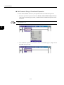
Select Multiple Objects
Selecting Objects in a Continuous Range
1. Select the beginning point in the continuous range.
2
2. Select the end point with the mouse and push the Shift key.
3. All objects are selected between them in continuous range.
INFO
1. <Key Operation>: Shift + Right/Left Arrow Key
2. This operation is available in a whole rung or within the same rung or the same branch.
2-52
2.7 EDIT OBJECT
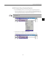
Selecting Objects in Non-Continuous Range
1. Select the beginning point in the non-continuous range.
2. Select the ending point with the mouse and press the Ctrl key.
INFO
<Key Operation>: move with Ctrl + Arrow Key, select with Ctrl + Enter
3. All objects are selected between them in non-continuous range.
2-53
2
2 PROGRAMMING
2.7.3 Edit Multiple Objects
Cut/Paste Multiple Objects
Multiple objects can be cut out and pasted to the another position.
1. Select the multiple objects and select Edit (E) - Cut (T) of the menu or from the pop-up
menu by the right-click.
INFO
<Key Operation>: Ctrl + X
2
2. The selected multiple objects are cut out and its information is saved in the clipboard.
3. Select the pasted position as the guide mark and select Edit (E) - Paste (P) of the menu
or from the pop-up menu by the right-click.
INFO
<Key Operation>: Ctrl + V
2-54
2.7 EDIT OBJECT
4. The result of Cut / Paste operation is displayed.
2
Copy/Paste Multiple Objects
Multiple objects can be copied and pasted to the another position.
1. Select the multiple objects and select Edit (E) - Copy (C) of the menu or from the pop-up
menu.
INFO
<Key Operation>: Ctrl + C
2-55
2 PROGRAMMING
2.7.3 Edit Multiple Objects
2. The selected multiple objects are copied and saved in the clipboard.
3. Select the pasted position as the guide mark and select Edit (E) - Paste (P) of the menu
or from the pop-up menu by the right-click.
INFO
<Key Operation>: Ctrl + V
2
4. The result of Copy/Paste operation is displayed.
2-56
2.7 EDIT OBJECT
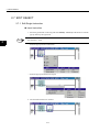
2.7.4 Undo
The edit process can be returned by the undo operation. Select Edit (E) - Undo (U) of the
menu or from the pop-up menu by the right-click.
INFO
<Key Operation>: Ctrl + Z
2.7.5 Redo
2
The edit process can be operated again after undo operation. Select Edit (E) - Redo (R) of the
menu or from the pop-up menu by the right-click.
INFO
<Key Operation>: Ctrl + Y
2-57
2 PROGRAMMING
2.8.1 Save
2.8 SAVE PROGRAM
There are two methods of saving the program, Save and Save All.
IMPORTANT
2
The program is saved in both the hard disk on PC and the controller in on-line mode, but it is saved in
only the hard disk on PC in the off-line mode.
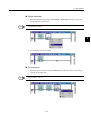
2.8.1 Save
An active program file is overwrote and saved.
1. Select File (F) - Save (S) of the menu.
INFO
<Key Operation>: Ctrl + S
2. An active program file is overwrote and saved.
2-58
2.8 SAVE PROGRAM
2.8.2 Save All
All opened program files are overwrote and saved.
1. Select File (F) - Save All (L) of the menu.
2
2. All opened program files are overwrote and saved.
2-59
2 PROGRAMMING
2.9.1 Verify
2.9 VERIFY PROGRAM
The program is compiled.
IMPORTANT
In the on-line mode, a program is saved to both PLC and a hard disk after verification is completed normally.
In the off-line mode, a program is saved to a hard disk it is not concemed with that verification is normal or error.
2
2.9.1 Verify
An active program file is compiled.
1. Select Edit (E) - Verify File (V) of the menu.
INFO
<Key Operation>: F8
2-60
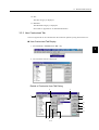
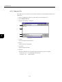
2.9 VERIFY PROGRAM
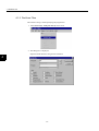
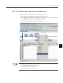
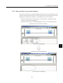
2. An active program file is verified. The result of the compile, warnings, and error messages are displayed in the output window.
3. The edit mark in the program disappears when verify is being executed.
2
4. The display on the tree of the file manager is changed from "Not Compiled File" to
"Compiled File" for the file from which verify was executed.
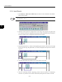
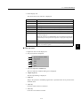
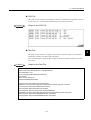
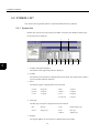
Error Display Format
EXAMPLE
When verify is executed, one example of the content of the display of the output window is
shown below.
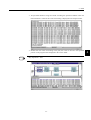
DWGH\H ( Rung 0, Step 1, Operand 0, Address): error C1041 : The operand is not available.
1
2
3
4
5
6
1. Program Name
The program name where error occurs is displayed.
2-61
2 PROGRAMMING
2.9.2 Verify All Program
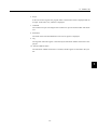
2. Rung Number
The rung number where error occurs is displayed.
3. Step Number
The step number where error occurs is displayed.
When the instruction does not exist on the rung, 0 is displayed.
4. Operand Information
The number and the type such as the symbol and the address, etc. of operand information
are displayed.
5. Error Code
2
The code of each error type to the error is displayed.
6. Detailed Information
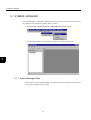
The error detailed content and method of the solution are displayed.
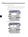
2.9.2 Verify All Program
All program files for the selected controller are verified.
1. Select Edit (E) - Verify All Program Files (F) of the menu.
2-62
2.9 VERIFY PROGRAM
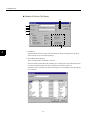
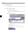
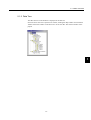
2. All program files for the selected controller are verified. The result of the compile, warnings, and error messages are displayed in the output window.
3. The edit mark in the program disappears when verify is being executed.
4. The display on the tree of the file manager is changed from "Not Compiled File" to
"Compiled File" for the file from which verify was executed.
INFO
Edit (E) - Verify (F) , Edit (E) - Verify All Program Files (F) operation is available from the
File Manager window as well as the Ladder Editor window.
2-63
2
2 PROGRAMMING
2.9.2 Verify All Program
2
2-64
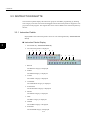
3
DISPLAY
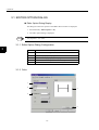
3.1 EDITOR OPTION DIALOG - - - - - - - - - - - - - - - - - - - - - - - - - 3-2
3.1.1 Editor Option Dialog Configuration - - - - - - - - - - - - - - - - - - - - - - - - - 3-2
3.1.2 Color - - - - - - - - - - - - - - - - - - - - - - - - - - - - - - - - - - - - - - - - - - - - - - 3-2
3.1.3 Font - - - - - - - - - - - - - - - - - - - - - - - - - - - - - - - - - - - - - - - - - - - - - - - 3-5
3.1.4 Ladder Display - - - - - - - - - - - - - - - - - - - - - - - - - - - - - - - - - - - - - - - 3-6
3.1.5 Control - - - - - - - - - - - - - - - - - - - - - - - - - - - - - - - - - - - - - - - - - - - - - 3-9
3.1.6 Key - - - - - - - - - - - - - - - - - - - - - - - - - - - - - - - - - - - - - - - - - - - - - - 3-10
3.2 ZOOM - - - - - - - - - - - - - - - - - - - - - - - - - - - - - - - - - - - - - - 3-11
3.3 INSTRUCTION PALETTE - - - - - - - - - - - - - - - - - - - - - - - - 3-12
3.3.1 Instruction Palette - - - - - - - - - - - - - - - - - - - - - - - - - - - - - - - - - - - - 3-12
3.3.2 User Customized Tab - - - - - - - - - - - - - - - - - - - - - - - - - - - - - - - - - - 3-13
3.3.3 Quick View Property - - - - - - - - - - - - - - - - - - - - - - - - - - - - - - - - - - 3-16
3.4 OUTPUT WINDOW - - - - - - - - - - - - - - - - - - - - - - - - - - - - - 3-18
3.4.1 Output Window Display - - - - - - - - - - - - - - - - - - - - - - - - - - - - - - - - 3-18
3.4.2 Detail of the Output Window - - - - - - - - - - - - - - - - - - - - - - - - - - - - - 3-19
3.5 TOOLBAR CUSTOMIZE DIALOG - - - - - - - - - - - - - - - - - - - 3-20
3.5.1 Display and Configuration of Toolbar Customize Dialog - - - - - - - - - 3.5.2 Commands - - - - - - - - - - - - - - - - - - - - - - - - - - - - - - - - - - - - - - - - 3.5.3 Toolbars - - - - - - - - - - - - - - - - - - - - - - - - - - - - - - - - - - - - - - - - - - 3.5.4 Keyboard - - - - - - - - - - - - - - - - - - - - - - - - - - - - - - - - - - - - - - - - - 3.5.5 Other - - - - - - - - - - - - - - - - - - - - - - - - - - - - - - - - - - - - - - - - - - - - 3.5.6 Edit Icon Image - - - - - - - - - - - - - - - - - - - - - - - - - - - - - - - - - - - - - 3.5.7 Customizing Operation - - - - - - - - - - - - - - - - - - - - - - - - - - - - - - - - -
3-20
3-20
3-21
3-22
3-23
3-24
3-28
3.6 FUNCTION KEYS - - - - - - - - - - - - - - - - - - - - - - - - - - - - - - 3-29
3.6.1 Function Bar - - - - - - - - - - - - - - - - - - - - - - - - - - - - - - - - - - - - - - - - 3-29
3.6.2 Function Key Assignment - - - - - - - - - - - - - - - - - - - - - - - - - - - - - - - 3-30
3-1
3
3 DISPLAY
3.1.1 Editor Option Dialog Configuration
3.1 EDITOR OPTION DIALOG
Editor Option Dialog Display
The dialog box where the options of the ladder editor window are displayed.
1. Select View (V) - Editor Options... (E).
2. The editor option dialog is displayed.
INFO
<Key Operation>: Alt + Enter
3.1.1 Editor Option Dialog Configuration
3
Tab
Explanation
Color
Set the color of the background, text, and lines in the ladder editor.
Font
Set the font property in the program window.
Ladder
Set the ladder display property in the program window.
Control
Set the max. number of open windows in the output window.
Key
Set the instruction names with a mnemonic key.
3.1.2 Color
1
2
4
3
5
3-2
3.1 EDITOR OPTION DIALOG
1. Setting Item
Select the item from the drop down list displayed with the menu button of the combo
box.
3
2. Category
This is available when "instruction" is selected. Click the menu button, and the category
of instruction is displayed.
3-3
3 DISPLAY
3.1.2 Color
3. Color
The color of the background, text, line is set.
Click the menu button and the color set box is displayed.
3
• Background
The background color is set.
• Text
The text color is set.
• Line
The line color is set.
4. Sample
The selections of a set item, the category, and the color, etc. are preview displayed.
5. Default
All settings in the color tab are returned to the default settings.
3-4
3.1 EDITOR OPTION DIALOG
3.1.3 Font
The font displayed in the program window is set.
1
4
2
3
3
5
1. Font Type
The selected font in the combo box list is displayed.
2. Attributes
• B : The bold-faced type is set or unset.
• I : The italic character type is set or unset.
• U : The underline of the character is set or unset.
3. Size
The font size is set.
4. Sample
The preview of the selected character is displayed.
5. Default
All settings in the font tab are returned to the default settings.
3-5
3 DISPLAY
3.1.4 Ladder Display
3.1.4 Ladder Display
A detailed display item in the program window is set.
1
10
2
11
3
12
13
4
14
5
15
6
3
16
17
7
18
8
19
9
20
21
Program Comment
1. Program Comment
Display/Hide of the program comment is set by the check box.
2. Max Lines
Unlimited: There is no limitation.
Limited (1-5): There is the limitation of the display number of lines of the program comment.
3. Alignment
The display positions in the program comment are set in either the left justification, the
center or the right justification.
Rung Comment
4. Rung Comment
Display/Hide of the rung comment is set by the check box.
5. Max Lines
Unlimited: There is no limitation.
Limited (1-5): There is the limitation of the display number of lines of the rung comment.
3-6
3.1 EDITOR OPTION DIALOG
6. Alignment
The display positions in the rung comment are set in either the left justification, the center or the right justification.
Rung
7. Rung Wrap
The rung turn control is available or not available is set by the check box.
8. Number of New Rungs
The number of rung when new program is created is set.
9. Number of Inserted Rungs
The number of rung when it is inserted is set.
Address
3
10. Address
Display/Hide of the address of the instruction is set by the check box.
11. Max Characters of Line
The maximum of characters a line is fixed by 14 now.
Symbol
12. Symbol
Display/Hide of the symbol of the instruction is set by the check box.
13. Max Characters of Line 10-20
The maximum number of characters on a line is set between 10 and 20.
14. Max Line
The maximum number of lines is set between 1 and 5 or set to no limit.
15. Word Wrap
The character string return function is set or not set by the check box.
Comment
16. Comment
Display/Hide of the comment of the instruction is set by the check box.
17. Max Characters of Line
The maximum number of characters on a line is set between 10 and 20.
18. Max Line
The maximum number of lines is set between 1 and 5.
19. Alignment
The display positions in the comment of the instruction are set in either the left justification, the center or the right justification.
3-7
3 DISPLAY
3.1.4 Ladder Display
20. Default
All settings in the ladder tab are returned to the default settings.
21. Others
The Expression and detailed program comment is set.
22
23
24
3
Expression
22. Max Characters of Line (1-512)
The maximum number of characters on a line is set between 1 and 512.
23. Word Wrap
The character string return function at more than the maximum number of characters
displayed is set or not set by the check box. When not set, the characters over the maximum of characters are not displayed.
Program Comment
24. New Program Default Comment
Character string as program comment is set, when new program is opened. "Program
Comment" is displayed as the default.
3-8
3.1 EDITOR OPTION DIALOG
3.1.5 Control
1
2
3
3
4
Output
1. Find Windows (1-10)
The number of windows displayed in the output window is set. The default number is
three.
Cursor action
2. Cursor in the Instruction moves with Enter key.
The cursor in the instruction moves with Enter key when the cursor is in the instruction.
3. Cursor in the Instruction moves with Tab key.
The cursor in the instruction moves with Tab key when the cursor is in the instruction.
Default button
4. All settings in the control tab are returned to the default settings.
3-9
3 DISPLAY
3.1.6 Key
3.1.6 Key
The allocation of shortcut commands for each instruction is displayed.
1
3
2
4
3
5
1. Key
Each shortcut command as mnemonic key is displayed.
2. Category
The category of instruction is displayed.
3. Instruction Name
The instruction name is displayed.
4. Explanation
The explanation for instruction is displayed.
5. Default
All settings in the key tab are returned to the default settings.
Change the mnemonic key
1. Move the cursor to the key to be changed.
2. Click the key item and it is changed to the edit mode.
3. Change the key and press the Enter key. This change is effective the next time the ladder
editor is started.
INFO
<Key Operation>: F2
3-10
3.2 ZOOM
3.2 ZOOM
The display scaling of the ladder window is set.
1. Select View (V) - Zoom (Z).
2. The zoom dialog box is displayed.
1
3
2
Zooming
1. Scale
Select the button for the prepared scale.
2. Select
Input the specified scale in the input box.
3-11
3 DISPLAY
3.3.1 Instruction Palette
3.3 INSTRUCTION PALETTE
The instruction palette displays the instruction group for the ladder programming by dividing
each category in the tab. The instruction dragged from the instruction palette is dropped on a target position in the program. The original tabs can be used or added on the instruction palette by
the user.
3.3.1 Instruction Palette
Display/Hide of the instruction palette can be set with selecting View (V) - Instruction Palette (I).
Instruction Palette Display
3
1. Select View (V) - Instruction Palette (I).
2. The instruction palette is displayed.
1
2
3
4
5
6
7
8
1. RELAY
The RELAY category is displayed.
2. MATH
The MATH category is displayed.
3. LOGIC
The LOGIC category is displayed.
4. CONTROL
The CONTROL category is displayed.
5. FUNCTION
The FUNCTION category is displayed.
6. MOVE
The MOVE category is displayed.
7. DDC
The DDC category is displayed.
8. TABLE
The TABLE category is displayed.
9. SYSTEM
The SYSTEM category is displayed.
3-12
9
10
11
3.3 INSTRUCTION PALETTE
10. SFC
The SFC category is displayed.
11. MOTION
The MOTION category is displayed.
Note: Refer to Appendix A for detailed information.
3.3.2 User Customized Tab
The user original tab can be customized on the instruction palette by using instructions on it.
User Customized Tab Display
1. Select Tool (T) - Customize User Tab... (C).
3
2. The customize user tab is displayed.
Details of Customize User Tab Dialog
2
3
1
8
9
10
11
12
13
4
5
6
3-13
7
3 DISPLAY
3.3.2 User Customized Tab
1. Available Instruction
All instructions of each category on the instruction palette are displayed.
2. Tab Title
The name of the edited user tab is displayed.
3. User Tab Instruction
The instruction registered in the user tab to be edited is displayed.
4. Add →
The instruction selected from available instruction window is registered in the user tab.
5. ← Remove
The specified instruction on the user tab is deleted.
6. Up
3
The cursor in the user tab instruction window moves to the upper direction.
7. Down
The cursor in the user tab instruction window moves to the lower direction.
8. OK
The Setting is reflected in the instruction palette, and the dialog is closed.
9. Cancel
The Setting is canceled, and the dialog is closed.
10. New
The user tab is newly created.
11. Rename
The edited user tab is renamed.
12. Delete
The edited user tab is deleted.
13. Tab Color
The background color for the edited user tab is set.
3-14
3.3 INSTRUCTION PALETTE
Set Customized User Tab
1. Select the New button.
Input the user tab name in the dialog.
2. Select the added instruction in the available instruction window.
3
3. Select the Add button and the selected instruction is registered in the user tab instruction
window.
4. Set the tab color and select the OK button, the specified user tab is added on the instruction palette.
3-15
3 DISPLAY
3.3.3 Quick View Property
3.3.3 Quick View Property
The quick view property sets the display form of the operand of the instruction.
Display/Hide of the quick view property can be set with selecting View (V) - Quick View
Property (V).
Quick View Property Display
1. Select View (V) - Quick View Property (V).
2. The quick view property is displayed.
3
1
2
3
4
5
6
7
8
1. Symbol/Comment/Address Display
The address, symbol, and comment of the instruction are all displayed.
2. Address/Comment Display
The address and comment of the instruction are displayed.
3. Symbol/Comment Display
The symbol and comment of the instruction are displayed.
3-16
3.3 INSTRUCTION PALETTE
4. Decrease the Number of Comment Lines
The number of comment lines displayed is decreased by one line at each click.
5. Increase the Number of Comment Lines
The number of comment lines displayed is increased by one line at each click.
3
6. Number of Comment Lines Display
The present number of comment lines is displayed.
7. Scope All On
The scope of all the instructions is turned on.
8. Scope All Off
The scope of all the instructions is turned off.
3-17
3 DISPLAY
3.4.1 Output Window Display
3.4 OUTPUT WINDOW
The output window is a window that shows the execution result of Find/Replace/Verify operation under the program window. The Display/Hide can be set with selecting View (V) - Output
(O) of the menu.
3.4.1 Output Window Display
1. Select View (V) - Output (O).
3
2. The output window is displayed under the program window.
3-18
3.4 OUTPUT WINDOW
3.4.2 Detail of the Output Window
1
2
3
1. Verify
The result of the verify execution, the warnings, the error messages are displayed in the
output window.
2. Find
The result of "Find All" operation is displayed. The number of windows that is changeable in the editor option dialog is set as the default.
3. Replace (supported in the future)
The result of "Replace All" operation is displayed.
3-19
3
3 DISPLAY
3.5.1 Display and Configuration of Toolbar Customize Dialog
3.5 TOOLBAR CUSTOMIZE DIALOG
3.5.1 Display and Configuration of Toolbar Customize Dialog
Toolbar Customize Dialog Box Display
The dialog box where the customized data of the toolbar is set is displayed.
1. Select View (V) - Toolbar (T) - Customize (C) of the menu or right-click on the toolbar
and select Customize (C).
2. The toolbar customize dialog box is displayed.
Toolbar Customize Dialog Configuration
3
Tab
Content
Commands
Display the list of commands added to the toolbar.
Toolbars
Create a new customized toolbar and rename it.
Keyboard
Set the shortcut key for each command.
Others
Set the properties of the menu and the toolbar.
3.5.2 Commands
1
2
3
4
1. Categories
Select the category of the command added to the toolbar.
2. Commands
The command list of the selected category is displayed.
3. Description
The description of the selected command is displayed.
4. Close
The toolbar customize dialog box is closed.
3-20
3.5 TOOLBAR CUSTOMIZE DIALOG
3.5.3 Toolbars
2
1
3
4
5
6
7
1. Toolbars
Set the check box of the toolbar.
2. Reset
Reset the selected standard toolbar. All customized data is removed from it. The button is
disabled when the user-defined toolbar is selected.
3. Reset All
Reset all standard toolbars except the user-defined toolbars.
4. New
Create a new user-defined toolbar. The toolbar name dialog box is displayed when the
button is selected. Input the toolbar name in the input box.
5. Rename
Rename the user-defined toolbar.
6. Delete
Delete the user-defined toolbar.
3-21
3
3 DISPLAY
3.5.4 Keyboard
7. Show text labels
Set the display/hide the button labels on the toolbar.
Display labels
Hide labels
3.5.4 Keyboard
3
10
1
3
6
2
7
8
4
9
5
1. Category
Select the category from the drop down list.
2. Commands
Select the command assigned to the shortcut key.
3. Current Keys
The current assigned shortcut key of the selected command is displayed.
4. Press New Shortcut Key
Input the shortcut key assigned to the selected command in the input box. It is automatically displayed as "Ctrl + C" when Ctrl + C is input.
5. Assigned to:
The current command assigned by the shortcut key input in the input box above is displayed. It is displayed, "Unassigned" when not assigned.
6. Assign
Assign the new shortcut key in the input box to the selected command.
3-22
3.5 TOOLBAR CUSTOMIZE DIALOG
7. Remove
Remove the assignment of the shortcut key from the selected command.
8. Reset All
Reset all assignments of the shortcut keys. The assignments of the shortcut keys returns
to the initial settings.
9. Description
The function description of the selected command is displayed.
10. Set Shortcut for:
Supported in the future.
3.5.5 Other
3
1
2
3
8
4
5
6
7
Toolbar
1. Screen tip
Set display/hide of the screen tip on the toolbar.
2. Display of shortcut key in the screen tip
Set display/hide of the shortcut key in the screen tip. This check box is available when
screen tip is set to display.
3. Icon type
Set large type for the icons on the toolbar.
3-23
3 DISPLAY
3.5.6 Edit Icon Image
Menu
4. Menu display type
Set the check box, recently used commands are first displayed in the menu.
5. Full menu display
Set the check box, all the commands are displayed after a few minutes are passed when
the cursor is put on the open menu. This check box is available when menu display type
is set.
6. Menu animations
Select the menu animation type to be None, Unfold, Slide, and Fade.
7. Menu shadows.
Set display/hide of the shadow of the menu.
3
8. Reset my usage data
Reset the menu display type changed by recent usage.
3.5.6 Edit Icon Image
1. Select View (V) - Toolbar (T) - Customize (C) of the menu or right-click on the toolbar
and select Customize (C).
2. The toolbar customize dialog box is displayed.
3. Right-click on the selected icon on the toolbar.
4. The pop-up menu is displayed.
Edit Operation
1. Reset to Default
Reset the button image and display form of the selected command.
2. Copy button image
Copy the button image of the selected command. It can be edited in the edit button
image dialog.
3. Delete
Delete the selected command on the toolbar.
3-24
3.5 TOOLBAR CUSTOMIZE DIALOG
4. Button Appearance
Modify the design of the selected button. The button appearance dialog is displayed.
5. Image
The image of the selected command is displayed.
6. Text
The text of the selected command is displayed.
7. Image and Text
The image and text of the selected command are displayed.
3
8. Start Group
Insert the separator at the left of the selected command.
Button Appearance Dialog
The button image assigned to the button is created and modified.
1. Select View (V) - Toolbar (T) - Customize (C) of the menu or right-click on the toolbar
and select Customize (C).
2. The toolbar customize dialog box is displayed.
3. Right-click on the selected icon on the toolbar.
4. The pop-up menu is displayed.
5. Select Button Appearance of the pop-up menu.
6. The button appearance dialog box is displayed.
2
1
4
5
6
3
7
3-25
3 DISPLAY
3.5.6 Edit Icon Image
1. Button display form
Select the display form of the button.
2. Select button image
Select the used button image.
3. User-defined image list
The user-defined images are displayed. It is available when the user-defined image is
selected.
4. New
Create a new button image of the command. The edit button image dialog is displayed. It
is available when the user-defined image is selected.
5. Edit
played. It is available when the user-defined image is selected.
6. Description
The function description of the selected command on the toolbar is displayed.
7. Button text
’
’
3
Edit the selected button image of the command. The edit button image dialog is dis-
Modify the caption of the selected button It is available when text only’ or image and
text’ is selected in the button display form.
Edit Button Image Dialog
The button image assigned to the button is edited.
1. Select View (V) - Toolbar (T) - Customize (C) of the menu or right-click on the toolbar
and select Customize (C).
2. The toolbar customize dialog box is displayed.
3. Right-click on the selected icon on the toolbar.
4. The pop-up menu is displayed.
5. Select Button Appearance of the pop-up menu.
6. The button appearance dialog box is displayed.
7. Select New (N) or Edit (E) button.
3-26
3.5 TOOLBAR CUSTOMIZE DIALOG
8. The edit button image dialog box is displayed.
2
1
3
3
4
1. Picture
Set or modify the button image by clicking the pixels of the picture.
2. Colors
Select the color of the button image.
3. Tools
Draw the picture using the tools.
4. Preview
The button image is previewed in actual size.
3-27
3 DISPLAY
3.5.7 Customizing Operation
3.5.7 Customizing Operation
Add Command
The customize dialog box is displayed.
1. Select the command tab.
2. Drag the selected icon.
3. Drop it to the selected toolbar.
Delete Command
The customize dialog box is displayed.
1. Drag the selected icon.
3
2. Drop it outside the toolbar
3-28
3.6 FUNCTION KEYS
3.6 FUNCTION KEYS
3.6.1 Function Bar
The function bar is displayed.
1. Select View (V) - Function Bar (U) from the menu.
2. The function bar is displayed.
The function keys are assigned below.
Function key
Function name
Content
F2
Edit
Put the selected object in editing.
F3
Show Key Assign
The key assignment in the edit option dialog is displayed. It can be
edited.
F8
Verify
Verify the program.
They following function keys are only displayed when using the symbol list in the ladder editor. The following function keys are only available when the symbol list is opened. Refer to
"5.5 OPERATION IN LADDER EDITOR" for details.
Function key
Function name
Content
F5
Find Next
Search for the next data.
F9
Sort
Sort the selected item.
F11
Program
Activate the program window.
F12
Symbol List
Activate the symbol list. Open the symbol list when it is not
opened. It can be edited.
3-29
3
3 DISPLAY
3.6.2 Function Key Assignment
3.6.2 Function Key Assignment
The function key assignment is displayed below including the Windows R standard assignment.
It can be changed at the toolbar customize dialog.
Function
key
Key operation
F key only
F1
Help
F2
Edit
F3
Show Key Assign
Shift + F key
3
Close
End
Find Next
F6
Next
F7
Switch Focus
F8
Verify
F9
Sort
F10
INFO
Alt + F key
Screen Tip
F4
F5
Ctrl + F key
Pop-up Menu
F11
Program
F12
Symbol List
The application like the front end processor occasionally uses the function key.
Be careful not to compete with that application, in changing the assignment of the function key.
3-30
4
FIND/REPLACE
4.1 FIND - - - - - - - - - - - - - - - - - - - - - - - - - - - - - - - - - - - - - - - - 4-2
4.1.1 Find - - - - - - - - - - - - - - - - - - - - - - - - - - - - - - - - - - - - - - - - - - - - - - - 4-2
4.1.2 Find from Files - - - - - - - - - - - - - - - - - - - - - - - - - - - - - - - - - - - - - - - 4-6
4.2 REPLACE - - - - - - - - - - - - - - - - - - - - - - - - - - - - - - - - - - - 4-10
4.3 CROSS REFERENCE - - - - - - - - - - - - - - - - - - - - - - - - - - - 4-14
4.3.1 Display Cross Reference Window - - - - - - - - - - - - - - - - - - - - - - - - - 4-14
4.3.2 Cross Reference Condition - - - - - - - - - - - - - - - - - - - - - - - - - - - - - - 4-16
4.3.3 Output to File - - - - - - - - - - - - - - - - - - - - - - - - - - - - - - - - - - - - - - - 4-18
4-1
4
4 FIND/REPLACE
4.1.1 Find
4.1 FIND
The specified character string is found in the ladder program and its location is displayed.
4.1.1 Find
The specified character string is found in the displayed ladder program.
1. Select Search (S) - Find (F) of the menu or from the pop-up menu.
INFO
<Key Operation > : Ctrl + F
4
2. The dialog box is displayed.
Input the found character string and the condition
4-2
4.1 FIND
3. Select the Find Next button and a specified character string is found according the specified condition. The cursor is moved to its position and it is displayed in the reverse
mode when there is a character string that meets it.
All specified character strings are found according the specified condition when the
Find All button is selected. The result of searching is displayed in the output window.
4
INFO
3 panes for finding displayed in the output window are prepared as a default. The default number is
changeable in the editor option window. The result of searching is usually displayed in the Search 1
pane and it is displayed in another pane when [Output New Pane] is checked
4. Double-click the result of searching in the pane, the cursor is moved to the specified
position in the program and is displayed in the reverse mode.
4-3
4 FIND/REPLACE
4.1.1 Find
Details of Find Dialog
2
1
3
4
4
5
1. Find Word
Input the found character string. The used character strings are displayed in the drop
down list and can be used when inputting it.
2. Select Word Dialog Display
This is available when Command is selected.
Select the button and the Select Word dialog box is displayed. The specified instruction
is set to the Command input box when clicking the instruction name in it.
The same word is reflected to the Find Word input box in Find dialog box when OK button is selected.
4-4
4.1 FIND
3. Parts
The sort of the found character string is set.
4. Direction
The direction of searching is set.
5. Other Conditions
The other condition is set.
• Use Wildcard
Wild-card (*,?) is made effective.
• Equal Check
The character string to which the whole is corresponding is found.
• Case Check
The capital letter and the small letter of the input character string are distinguished.
• All Program
All programs opened now are searched.
• Output New Pane
When the Find All button is selected, the result of searching is displayed in the output
window as a new pane.
• Wrap
The cursor position wraps entire file when the Find Next button is pushed and the
searching is ended.
• Correct Address
When the Address check box of Parts turns on, The register address input is corrected
to regular shape. For instance, MW1 is corrected to MW00001.
4-5
4
4 FIND/REPLACE
4.1.2 Find from Files
4.1.2 Find from Files
The character string is found specifying the program file.
1. Select Search (S) - Find from File (I) of the menu.
2. The dialog box is displayed.
Input the found character string and the condition.
4
4-6
4.1 FIND
3. All specified character strings are found according the specified condition when the
Find All button is selected. The result of searching is displayed in the output window.
4. Double-click the result of searching in the pane, the cursor is moved to the specified
position in the program and is displayed in the reverse mode.
INFO
<Key Operation> : Enter
4-7
4
4 FIND/REPLACE
4.1.2 Find from Files
Details of Find for File Dialog
24
1
3
5
6
7
8
4
1. Find Word
Input the found character string. The used character strings are displayed in the drop
down list and can be used when inputting it.
2. Select Word Dialog Display
This is available when Command is selected.
Select the button and the Select Word dialog box is displayed. The specified instruction
is set to the Command input box when clicking the instruction name in it.
The same word is reflected to the Find Word input box in Find dialog box when OK button is selected.
4-8
4.1 FIND
3. File Directory (supported in the future)
Input the found folder. The used folder names are displayed in the drop down list and
can be used when inputting it.
4. Select Folder Dialog Display (supported in the future)
Select the button and the Select Folder dialog box is displayed. The specified folder is
set to the Folder input box when clicking the folder in it.
The same folder is reflected to the Find Directory input box in Find for File dialog box
when OK button is selected.
4
5. File Type
The found file name is set. The used file name are displayed in the drop down list and
can be used when inputting it.
6. Program Type (supported in the future)
7. Parts
The sort of the found character string is set.
8. Other Conditions
The other condition is set.
4-9
4 FIND/REPLACE
4.2 REPLACE
The specified character string is found and replaced in the ladder program.
1. Select Search (S) - Replace (P) of the menu or from the pop-up menu.
INFO
4
<Key Operation> : Ctrl + H
2. The dialog box is displayed.
Input the found character string, the replaced character string, and the condition.
4-10
4.2 REPLACE
3. Select the Replace button and a specified character string is found according the specified condition and replaced. The cursor is moved to next found position after replaced
and it is displayed in the reverse mode when there is a character string that meets it.
4
4. All specified character strings are found according the specified condition when the
Replace All button is selected. The result of replacing is displayed in the output window.
5. Double-click the result of replacing in the pane, the cursor is moved to the specified
position in the program and is displayed in the reverse mode.
4-11
4 FIND/REPLACE
Details of Replace Dialog
2
1
3
4
5
4
6
7
1. Find Word
Input the found character string. The used character strings are displayed in the drop
down list and can be used when inputting it.
2. Select Word Dialog Display
This is available when Command is selected.
Select the button and the Select Word dialog box is displayed. The specified instruction
is set to the Command input box when clicking the instruction name in it.
The same word is reflected to the Find Word input box in Find dialog box when OK button is selected.
4-12
4.2 REPLACE
3. Replace Word
Input the replaced character string. The used character strings are displayed in the drop
down list and can be used when inputting it.
4. Range
The replaced range is set.
• File
All specified character strings are replaced in the active program file.
• Selected Range
All specified character strings are replaced in the selected range.
5. Parts
The sort of the found character string is set.
6. Direction
The direction of searching is set.
7. Other Conditions
The other condition is set.
4-13
4
4 FIND/REPLACE
4.3.1 Display Cross Reference Window
4.3 CROSS REFERENCE
The cross reference function is used to search how and in which program a symbol or a register
is used.
4.3.1 Display Cross Reference Window
The cross reference window is displayed.
1. Select View (V) - Cross Reference Data (F) from the menu.
2. The cross reference window is displayed on the ladder editor window in the docked
mode.
Cross Reference Configuration
4
1
2
3
1. Cross reference condition display
The executive condition of the cross reference is displayed.
2. Menu display button
The menu of the cross reference function is displayed when the button is clicked.
4-14
4.3 CROSS REFERENCE
3. Result display area
The result of the cross reference is displayed.
Item
Explanation
Address
The register address is displayed.
Symbol
The symbol is displayed.
Program Name
The program name in which the searched object is used is displayed.
Rung Number
The rung number of the searched object is displayed.
Step Number
The step number of the searched object is displayed.
Instruction Name
The instruction name in which the searched object is used is displayed.
Parameter Number
The parameter number of instruction name in which the searched object
is used is displayed.
When the instruction is EXPRESSION, the line number that includes the
searched object in the operational expression is displayed with parentheses.
Attribute
The read or write attribute is displayed.
Use Address
The address is displayed when same memory searching check box is set
in the cross reference option.
Pop-up menu
1. Right-click in the result display area.
2. The pop-up menu is displayed.
1
2
3
4
5
1. Set cross reference condition (S)
The cross reference condition dialog box is displayed.
2. Output to file (F)
The file output dialog is displayed.
3. Jump (J)
Jump to the position in the ladder program that is specified at the cursor position in the
searched result.
4. Clear (L)
Clear the result of the cross reference.
5. Close (C)
Close the cross reference window.
4-15
4
4 FIND/REPLACE
4.3.2 Cross Reference Condition
4.3.2 Cross Reference Condition
The cross reference condition dialog box is displayed from the menu button or the pop-up
menu.
In the cross reference condition dialog, the symbol or the register is selected as a cross reference condition. The input item of the screen is different according to the selection.
When the symbol is selected
9
1
10
11
2
4
4
5
8
7
When the register is selected
9
1
10
3
11
4
5
8
6
4-16
4.3 CROSS REFERENCE
1. Data Type
Select the symbol or the register.
2. Symbol
Input the searched symbol name.
The symbol names can be set up to 30 at the same time.
3. Register
Input the range (Start Register and End Register) of the searched register.
Ranges of the register can be set up to 30 at the same time.
4. Program name
Input the searched program name. The wild-card (*) is available.
EXAMPLE
All H program is searched when H* is input as a program name.
5. Setting History
A set condition is selected from the history.
The set condition input in the past is memorized as the history.
The latest history becomes "History -1".
6. Same memory searching
It is available when the register is selected. All registers which use the same memory are
searched. For example, when MW00000-MW00010 is specified, MB000000MB00001F, ML00000-ML00010, and MF00000-MF00010 are also searched.
7. Case check
It is available when the symbol is selected. The upper case and lower case are distinguished.
8. Attribute
Set the attribute of the searched symbol or register used in the program.
9. Execute
Execute the cross reference.
10. Cancel
Cancel the crossing reference condition dialog.
11. Option
Display the cross reference options.
4-17
4
4 FIND/REPLACE
4.3.3 Output to File
4.3.3 Output to File
The result of the cross reference can be output to the file by Comma Separated Value or the
TEXT form.
1. Click Cross Reference button. Or, right-click in the result display area.
2. Select Output to file (F).
3. The file output dialog is displayed.
1
2
3
4
4
1. Look in
Select the folder for the output file.
2. File list
The list of the file is displayed.
3. File name
Input the output file name.
4. File type
Select the output file type. Two kinds of the following file type are available.
• Data Files (*.csv): Comma Separated Value file
• Text file (*.txt) :
TEXT form file
4-18
4.3 CROSS REFERENCE
CSV File
The result of cross reference is formatted by comma (",") delimitation and output to the file
as CSV file (.csv). It is opened and edited easily with a tool such as Excel.
EXAMPLE
Output to the CSV File
Text File
The result of cross reference is output to the file by the character string. It is opened and
edited easily with any text editor such as Notepad.
The crossing reference condition data is output to the file as a header with the cross reference result.
EXAMPLE
Output to the Text File
Target Order name:GROUP920 PLC name:MP01\CPU1
Time 2000/09/27 11:45
Cross type Register:MW00000 thru MW00100
File name:H*
Same memory search:On
Attribute:Read/Write/Read-Write
Register Count Cross reference Symbol Comment
MW00001 4 H01,Rung-0001,Step-0010,STORE,Param-00,Read Symbol1 Comment1
H01,Rung-0002,Step-0013,STORE,Param-00,Read
H01,Rung-0003,Step-0020,ADD,Param-02,Write
H20,Rung-0001,Step-0011,NOC,Param-00,Read,MB00001F
MW00050 3 H02,Rung-0000,Step-0000,INC,Param-00,Read-Write Symbol2 Comment2
H02,Rung-0001,Step-0001,EXPRESSION,Param-00(2),Read
H02,Rung-0001,Step-0001,EXPRESSION,Param-00(2),Write
4-19
4
4 FIND/REPLACE
4.3.3 Output to File
4
4-20
5
SYMBOL DATABASE
The symbol database offers the function to manage the symbol to the register
and the data of the comment etc. and also offers the method of data acquisition
of the ladder editor’s not depending on the controller type.
5.1 SYMBOL MANAGER - - - - - - - - - - - - - - - - - - - - - - - - - - - - 5-2
5.1.1 Symbol Manager Menu - - - - - - - - - - - - - - - - - - - - - - - - - - - - - - - - - 5-2
5.1.2 Data Tree - - - - - - - - - - - - - - - - - - - - - - - - - - - - - - - - - - - - - - - - - - - 5-3
5.2 SYMBOL LIST - - - - - - - - - - - - - - - - - - - - - - - - - - - - - - - - - 5-4
5.2.1 Symbol List - - - - - - - - - - - - - - - - - - - - - - - - - - - - - - - - - - - - - - - - - - 5-4
5.2.2 Add Symbol - - - - - - - - - - - - - - - - - - - - - - - - - - - - - - - - - - - - - - - - - 5-6
5.2.3 Insert Symbol - - - - - - - - - - - - - - - - - - - - - - - - - - - - - - - - - - - - - - - - 5-7
5.2.4 Delete Symbol - - - - - - - - - - - - - - - - - - - - - - - - - - - - - - - - - - - - - - - - 5-8
5.2.5 Import Symbol Data - - - - - - - - - - - - - - - - - - - - - - - - - - - - - - - - - - - - 5-9
5.2.6 Export Symbol Data - - - - - - - - - - - - - - - - - - - - - - - - - - - - - - - - - - - 5-10
5.2.7 Find/Replace - - - - - - - - - - - - - - - - - - - - - - - - - - - - - - - - - - - - - - - - 5-11
5.3 REGISTER MAP - - - - - - - - - - - - - - - - - - - - - - - - - - - - - - - 5-16
5.3.1 Register Map - - - - - - - - - - - - - - - - - - - - - - - - - - - - - - - - - - - - - - - - 5-16
5.4 AUTOMATIC ADDRESS ALLOCATION - - - - - - - - - - - - - - 5-18
5.4.1 Automatic Address Allocation - - - - - - - - - - - - - - - - - - - - - - - - - - - - 5-18
5.4.2 Setting of Register Area - - - - - - - - - - - - - - - - - - - - - - - - - - - - - - - - 5-19
5.4.3 Execution of Automatic Address Allocation - - - - - - - - - - - - - - - - - - - 5-20
5.5 OPERATION IN LADDER EDITOR - - - - - - - - - - - - - - - - - - 5-21
5.5.1 Display Symbol List - - - - - - - - - - - - - - - - - - - - - - - - - - - - - - - - - - - 5-21
5.5.2 Display Register Map - - - - - - - - - - - - - - - - - - - - - - - - - - - - - - - - - - 5-23
5.5.3 Unregistered Symbol List - - - - - - - - - - - - - - - - - - - - - - - - - - - - - - - 5-26
5-1
5
5 SYMBOL DATABASE
5.1.1 Symbol Manager Menu
5.1 SYMBOL MANAGER
The symbol manager is composed as MDI application that consists of the three windows such as
the symbol list, the register map, and the data tree window.
1. Select Tool (T) - Symbol System (S) - Symbol Manager (S) of the menu.
2. The symbol manager is started and the only Data Tree window is displayed.
5
5.1.1 Symbol Manager Menu
The edit functions of the symbol manager are prepared in the menu. The functions often used
in the menu are prepared on the tool bar.
5-2
5.1 SYMBOL MANAGER
5.1.2 Data Tree
The data structure in the database is displayed in the data tree.
Select the items such as the Symbol List window, the Register Map window and Automatic
Address Allocation window in the data tree to access the data. The selected window is displayed.
5
5-3
5 SYMBOL DATABASE
5.2.1 Symbol List
5.2 SYMBOL LIST
The content of the registered symbols is referred and defined in the symbol list.
5.2.1 Symbol List
Double-click the All list on the Symbol List folder in the Data Tree Window and the registered symbol list is displayed.
1
5
2
3
4
5
10
6
7
8
9
1. Number of Registered Symbol
The number of the registered symbol is displayed.
2. Symbol
The symbol of the instruction is displayed and can be input. The length of the symbol is
up to the normal-width 64 characters.
3. Kind
The kind of register is displayed and can be selected.
• Global
: M register
• Input
: I register
• System
: S register
• Output
: O register
• Const
: C register
• Local
: D register
• LocalConst
: # register
4. Data Type
The data type of register is displayed and can be selected.
• Bit
: Bit type
• Long
: Double Integer-type
• Word
: Integer type
• Float
: Real type
• Address
: Address type
5. Register
The register address of the instruction is displayed and can be input.
5-4
5.2 SYMBOL LIST
6. Scope
In the case of local register, the program name or the function name is displayed and can
be input. In the other case, "Global" is displayed.
7. Comment
The comment is input. The length of the comment is up to the normal-width 100 characters.
8. Struct/Size
The name of the structured definition or the size of register is displayed.
9. Tag
The tag name when the register is allocated by the Automatic Address Allocation is displayed.
10. Allocate Address button
The Automatic Address Allocation is executed, and the register is allocated in the symbol.
5
5-5
5 SYMBOL DATABASE
5.2.2 Add Symbol
5.2.2 Add Symbol
The new symbol definition is added to the symbol list.
1. Select Edit (E) - Add (A) of the menu.
2. A new symbol definition data is added in the bottom of the symbol list.
5
3. Select File (F) - Save (S) of the menu after inputting data.
4. The message is displayed and the registration of new symbol is completed.
5-6
5.2 SYMBOL LIST
5.2.3 Insert Symbol
The new symbol definition is inserted to the symbol list.
1. Select Edit (E) - Insert (I) of the menu.
2. A new symbol definition data is inserted on the cursor position in the symbol list.
5
3. Select File (F) - Save (S) of the menu after inputting data.
4. The message is displayed and the registration of new symbol is completed.
5-7
5 SYMBOL DATABASE
5.2.4 Delete Symbol
5.2.4 Delete Symbol
The selected symbol definition is deleted in the symbol list.
1. Move the cursor to the deleted symbol definition data and select Edit (E) - Delete (D) of
the menu.
INFO
<Key Operation>: Delete
2. The symbol definition data on the cursor position is deleted and the following lines are
shifted up by one step.
3. Select File (F) - Save (S) of the menu.
5
INFO
<Key Operation>: Ctrl + S
4. The message is displayed and the registration of new symbol is completed.
5-8
5.2 SYMBOL LIST
5.2.5 Import Symbol Data
The symbol data is imported from CSV data file.
1. Select File (F) - Import (I) of the menu and the Open dialog box is displayed.
2. Select the imported CSV data file.
5
3. The data of the selected CSV data file is reflected to the symbol list and displayed on the
cursor position.
5-9
5 SYMBOL DATABASE
5.2.6 Export Symbol Data
5.2.6 Export Symbol Data
The symbol data in the symbol list is exported to CSV data file.
1. Select File (F) - Export (E) of the menu and the Save As dialog box is displayed.
2. Set the name of the exported CSV data file, and select Save (S) button.
5
3. The selected one or more symbol data is exported to the specified file.
5-10
5.2 SYMBOL LIST
5.2.7 Find/Replace
The specified character string is found and replaced in the Symbol List.
Find
The specified character string is found in the displayed Symbol List.
1. Select Search (S) - Find (F) of the menu or from the pop-up menu.
INFO
< Key Operation >: Ctrl + F
2. The dialog box is displayed. Input the found character string and the condition.
5
Select the Find Next button and a specified character string is found according the specified condition. The cursor is moved to its position and it is displayed in the reverse mode
when there is a character string that meets it.
3. All specified character strings are found according the specified condition when the Find
All button is selected. The result of searching is displayed in the output window.
5-11
5 SYMBOL DATABASE
5.2.7 Find/Replace
INFO
3 panes for finding displayed in the output window are prepared. The result of searching is usually displayed in the Search 1 pane and it is displayed in another pane when [Output New Pane] is checked.
4. Double-click the result of searching in the pane, the cursor is moved to the specified
position in the program and is displayed in the reverse mode.
Details of Find Dialog
1
2
5
3
4
1. Find Word
Input the found character string. The used character strings are displayed in the drop
down list and can be used when inputting it.
2. Parts
The sort of the found character string is set.
3. Direction
The direction of searching is set.
4. Other Conditions
The other condition is set.
• Use Wildcard
Wild-card (*,?) is made effective.
• Equal Check
The character string to which the whole is corresponding is found.
• Case Check
The capital letter and the small letter of the input character string are distinguished.
• Output New Pane.
When the Find All button is selected, the result of searching is displayed in the output
5-12
5.2 SYMBOL LIST
window as a new pane.
• Wrap
The cursor position wraps the entire file when the Find Next button is pushed and the
serching is ended.
• Correct Address
When the Address check box of Parts turns on, The register address input is corrected
to regular shape. For instance, MW1 is corrected to MW00001.
Replace
The specified character string is found and replaced in the Symbol List.
1. Select Search (S) - Replace (P) of the menu or from the pop-up menu.
INFO
< Key Operation >: Ctrl + H
2. The dialog box is displayed.
Input the found character string, the replaced character string, and the condition.
5
3. Select the Replace button and a specified character string is found according the specified condition and replaced. The cursor is moved to next found position after replaced
and it is displayed in the reverse mode when there is a character string that meets it.
4. All specified character strings are found according the specified condition when the
Replace All button is selected. The result of replacing is displayed in the output window.
5-13
5 SYMBOL DATABASE
5.2.7 Find/Replace
5. Double-click the result of replacing in the pane, the cursor is moved to the specified position in the program and is displayed in the reverse mode.
5
5-14
5.2 SYMBOL LIST
Details of Replace Dialog
1
2
3
4
5
6
1. Find Word
Input the found character string. The used character strings are displayed in the drop
down list and can be used when inputting it.
2. Replace Word
Input the replaced character string. The used character strings are displayed in the drop
down list and can be used when inputting it.
3. Range
The replaced range is set.
• File
All specified character strings are replaced in the Symbol List.
• Selected Range
All specified character strings are replaced in the selected range.
4. Parts
The sort of the found character string is set.
5. Direction
The direction of searching is set.
6. Other Conditions
The other condition is set.
5-15
5
5 SYMBOL DATABASE
5.3.1 Register Map
5.3 REGISTER MAP
The presence of the symbol for the register is arranged according to the data type and displayed
in the register map.
5.3.1 Register Map
Double-click the each list on the Register folder in the Data Tree window and the register
map is displayed. The displayed screen is different in a global register and a local register.
Local Register
2
1
5
3
5
4
Global Register
1
2
3
4
5-16
5.3 REGISTER MAP
Display Mode
1. BWLFA button
The presence of the symbol for the register is displayed all data type such as bit type,
integer type, double integer type, real type, and address type simultaneously. The data
type in which the symbol is defined is displayed in each cell by combining alphabets.
2. Other buttons
The presence of the symbol for the register is displayed each data type. The "*" mark is
displayed when the symbol is defined.
3. Start Address
The start address of the displayed register is set. The cursor is moved to the specified
register address cell.
4. Address
The addresses of register are displayed from the specified start address.
5. Scope
The program name or the function name is displayed and can be input.
5-17
5
5 SYMBOL DATABASE
5.4.1 Automatic Address Allocation
5.4 AUTOMATIC ADDRESS ALLOCATION
An automatic address allocation is a function to allocate register address in the symbol automatically.
The address of the register used for the automatic allocation should set the address area on the
Automatic Address Allocation window. An automatic address allocation to the symbol becomes
possible by the automatic address allocation function of the Symbol List.
5.4.1 Automatic Address Allocation
Double-click the Area Setting file on the Automatic Address Allocation folder in the Data
Tree window and the Automatic Address Allocation window is displayed.
5
1. Start Address
The start address in the target area for an automatic address allocation is displayed and
can be input.
2. End Address
The end address in the target area for an automatic address allocation is displayed and
can be input.
3. Size
The number of words of the target area for an automatic address allocation is displayed
and can be input.
4. Scope
In the case of local register (D register), the program name or the function name is displayed and can be input. In another case, Global (M register) is displayed.
5. Comment
The comment is input. The comment set here becomes a comment which is used on the
automatic numbering function of the Symbol List. The length of the comment is up to
the normal-width 100 characters.
6. Tag
The tag name to the target area for an automatic address allocation is displayed and can
be input.
5-18
5.4 AUTOMATIC ADDRESS ALLOCATION
5.4.2 Setting of Register Area
The target register area for an automatic address allocation is set.
Setting data can be edited by the menu (cut , copy, paste, and delete).
1. Input the data to the item.
It is automatically adjusted by inputting either End Address or Size.
2. The edit menu is selected from Edit (E) of the menu.
5
3. Select File (F) - Save (S) of the menu after inputting data.
INFO
<Key Operation >: Ctrl + S
4. The message is displayed and the setting of register area is completed.
5-19
5 SYMBOL DATABASE
5.4.3 Execution of Automatic Address Allocation
5.4.3 Execution of Automatic Address Allocation
The automatic address allocation to the symbols is executed in the Symbol List.
1. Open the Symbol List, and set Tag name of the symbol where the register is not allocated.
5
2. Select Edit (E) - Automatic Address Allocation (T) or the Allocate Address button.
3. The register is automatically allocated to the symbol.
5-20
5.5 OPERATION IN LADDER EDITOR
5.5 OPERATION IN LADDER EDITOR
5.5.1 Display Symbol List
1. Select Tool (T) - Symbol System (S) - Symbol List (L) from the menu.
2. The symbol list is displayed in the ladder editor. It can be edited.
INFO
Open the symbol list from the symbol manager if the edit operation is required.
Search
The search function is opened in the symbol list.
1
1. Search Data
Input the specified data. The cursor immediately moves to the position that input data
shows.
INFO
1. Click the title of each item of the symbol list, the data is sorted.
2. The upper case and lower case are not distinguished.
3. The wild card (*) is not available.
Using Function Key
Search the specified data using the function key.
1. Select F12, and then the symbol list is displayed.
2. Select F9, and then the specified data is sorted.
5-21
5
5 SYMBOL DATABASE
5.5.1 Display Symbol List
3. Select F2, and then the specified data is put in editing.
4. Select F5, and then the cursor moves to next data.
Input Symbol Data to Ladder Program
1. Select the specified symbol in the symbol list.
2. Right-click on it and select Copy (C) of the menu.
3. Select the instruction that requires the symbol in the ladder program.
4. Right-click on it, and select Paste (P).
5
5. The data of the symbol list is input to the specified instruction in the ladder program.
INFO
The shortcut keys are as follows.
Copy (C) : Ctrl + C, Paste (P) : Ctrl + V
Switch the activated screen using function keys such as F11 and F12. Select F11, and then the ladder
program is activated. Select F12, and then the symbol list is activated.
5-22
5.5 OPERATION IN LADDER EDITOR
5.5.2 Display Register Map
1. Select Tool (T) - Symbol System (S) - Register Map (R) of the menu in the ladder editor.
2. The register map window is displayed on the program window as the docking view.
5
3. The map of the register used by the program is displayed.
4. Click the Program specification button, and select the programs.
5-23
5 SYMBOL DATABASE
5.5.2 Display Register Map
Click the Refresh button, then Register Map is refreshed.
5
5-24
5.5 OPERATION IN LADDER EDITOR
5. Click the Display Mode button, then display mode is changed.
• BWLFA button
The presence of the symbol for the register is displayed all data type such as bit
type (B), integer type (W), double integer type (L), real type (F), and address type (A)
simultaneously. The data type in which the symbol is defined is displayed in each cell
by combining alphabets
• Other buttons
The presence of the symbol for the register is displayed each data type. The "*" mark
is displayed when the symbol is defined.
5
5-25
5 SYMBOL DATABASE
5.5.3 Unregistered Symbol List
5.5.3 Unregistered Symbol List
The new symbols in the ladder program are assigned to the unregistered symbol list.
The unregistered symbol can be assigned to the symbol database in the unregistered symbol
list.
Display Unregistered Symbol List
1. Select Tool (T) - Symbol System (S) - Unregistered symbol list (U) from the menu.
2. The unregistered symbol list window is displayed in the docked mode. The symbols that
have not been registered to the symbol database can be viewed.
5
5-26
5.5 OPERATION IN LADDER EDITOR
Unregistered Symbol List
1
2
3
4
5
6
1. Number of unregistered symbols
The total number of the unregistered symbol is displayed.
2. All select
Select all unregistered symbols.
3. DB update
Assign the selected unregistered symbol to the symbol database.
4. Export
Export the symbol list to a CSV file. Please refer to paragraph "5.2.6 Export Symbol
Data" for the operation procedure.
5. Alocate address
Register address is automatically allocated to the symbol which the register is not allocated.
Refer Automatic Address Allocation for this function.
6. Unregistered symbol list
The unregistered symbols are displayed, sorted and can be edited.
DB Update
1. Select the unregistered symbol to be assigned to the symbol database.
2. Click the DB Update.
3. The unregistered symbol is assigned to the symbol database and the symbol database is
updated.
5-27
5
5 SYMBOL DATABASE
5.5.3 Unregistered Symbol List
5
5-28
6
DEBUGGING
A monitoring and debugging the ladder program, a displaying the current
value, a synchronized collection of current value, and the setting disable coil
instruction are explained.
6.1 BASIC FUNCTION - - - - - - - - - - - - - - - - - - - - - - - - - - - - - - 6-2
6.1.1 Display Current Values - - - - - - - - - - - - - - - - - - - - - - - - - - - - - - - - - - 6-2
6.1.2 SYNC - - - - - - - - - - - - - - - - - - - - - - - - - - - - - - - - - - - - - - - - - - - - - - 6-3
6.1.3 HOLD (supported in the future) - - - - - - - - - - - - - - - - - - - - - - - - - - - - 6-4
6.2 DISABLE COILS - - - - - - - - - - - - - - - - - - - - - - - - - - - - - - - - 6-5
6.2.1 Display - - - - - - - - - - - - - - - - - - - - - - - - - - - - - - - - - - - - - - - - - - - - 6.2.2 Set Disable ON - - - - - - - - - - - - - - - - - - - - - - - - - - - - - - - - - - - - - - 6.2.3 Set Disable OFF - - - - - - - - - - - - - - - - - - - - - - - - - - - - - - - - - - - - - 6.2.4 Cancel Disable - - - - - - - - - - - - - - - - - - - - - - - - - - - - - - - - - - - - - - -
6-5
6-6
6-6
6-7
6.3 REFER - - - - - - - - - - - - - - - - - - - - - - - - - - - - - - - - - - - - - - 6-8
6.3.1 Refer on the SEE Instruction - - - - - - - - - - - - - - - - - - - - - - - - - - - - - - 6-8
6.3.2 Refer on the FUNC Instruction - - - - - - - - - - - - - - - - - - - - - - - - - - - - 6-9
6.4 QUICK REFERENCE - - - - - - - - - - - - - - - - - - - - - - - - - - - 6-10
6.4.1 Display - - - - - - - - - - - - - - - - - - - - - - - - - - - - - - - - - - - - - - - - - - - 6.4.2 Register List Page - - - - - - - - - - - - - - - - - - - - - - - - - - - - - - - - - - - 6.4.3 Watch Page - - - - - - - - - - - - - - - - - - - - - - - - - - - - - - - - - - - - - - - 6.4.4 The definition data is added from the ladder editor. - - - - - - - - - - - - -
6-10
6-11
6-14
6-17
6.5 CURRENT VALUE MONITOR - - - - - - - - - - - - - - - - - - - - - 6-18
6.5.1 Display of Current Value Monitor Window - - - - - - - - - - - - - - - - - - - 6-18
6.5.2 Start and Stop Current Value Monitor - - - - - - - - - - - - - - - - - - - - - - - 6-21
6.5.3 Pop-up Menu - - - - - - - - - - - - - - - - - - - - - - - - - - - - - - - - - - - - - - - 6-22
6-1
6
6 DEBUGGING
6.1.1 Display Current Values
6.1 BASIC FUNCTION
The following functions are valid for monitoring/debugging.
• Current value display
• SYNC function
• HOLD function (supported in the future)
6.1.1 Display Current Values
In the online mode, the current values can be displayed at the same time as the program displayed. The current values are renewed constantly and the newest data will be displayed.
The current value of each instruction is as follows.
Contact
The open/close status of a contact is displayed in the program. The close status is distinguished from the different color.
6
Coil
The energized/de-energized status of a coil is displayed in the program. The energized status
is distinguished from the different color.
6-2
6.1 BASIC FUNCTION
Operand
The value of the operand for an operation is displayed below the format.
INFO
Select Tool (T) - Editor Option (E) of the menu to set the color.
6.1.2 SYNC
The SYNC is available in only the on-line mode. Its operation is disabled in the off-line mode.
The current values of a program at the time at which the specified register (S, I, O, M, D, C, #)
or a subscript register I or J takes on certain value or when the ON/OFF condition of a designated relay No. is satisfied can be displayed. The current value display is renewed when the designated condition is satisfied and will remain the same if condition is not satisfied. Up to 2
synchronization conditions may be set. If two conditions are set, an AND condition is used.
1. Select Debug (D) - SYNC (S) of the menu.
6-3
6
6 DEBUGGING
6.1.3 HOLD (supported in the future)
2. The dialog box is displayed.
Input the required data and set the check box, and select Set button .
3. The current value display is renewed when the designated condition is satisfied and
remains the same if the condition is not satisfied.
6.1.3 HOLD (supported in the future)
The collecting current values are stopped temporarily.
1. Select Debug (D) - HOLD (H) of the menu.
6
2. When the HOLD function is executed again with the collection of current values being
stopped temporarily the collection of current values restarts.
6-4
6.2 DISABLE COILS
6.2 DISABLE COILS
The coil instruction can be forcibly fixed to ON, the energized condition (Disable ON), and to
OFF, the de-energized condition (Disable OFF).
6.2.1 Display
The display of Disable ON/OFF coil is as follows.
Coil
Set Coil
6
Reset Coil
6-5
6 DEBUGGING
6.2.2 Set Disable ON
6.2.2 Set Disable ON
Set the coil instruction to forcibly fix to the ON status during the execution of a program.
1. Move the cursor to the coil instruction to be set to Disable ON. Select Debug (D) Force On (O) of the menu.
2. The coil is expressed as being under the Disable ON status.
6
6.2.3 Set Disable OFF
Set the coil instruction to forcibly fix to the OFF status during the execution of a program.
1. Move the cursor to the coil instruction to be set to Disable ON. Select Debug (D) Force Off (F) of the menu.
6-6
6.2 DISABLE COILS
2. The coil is expressed as being under the Disable OFF status.
6.2.4 Cancel Disable
Cancel the Disable setting of the coil instruction.
1. Move the cursor to the coil instruction to cancel the Disable. Select Debug (D) Remove Force (V) of the menu.
6
2. The coil is turned to normal condition.
6-7
6 DEBUGGING
6.3.1 Refer on the SEE Instruction
6.3 REFER
When the REFER function is executed with the cursor being at a SEE instruction or a user function name, jumping is performed to a DWG program or user function program screen in the online mode. The current values at the time at which the SEE instruction or the user function referencing FSTART instruction was executed can thus be displayed.
6.3.1 Refer on the SEE Instruction
1. Open the program in the on-line mode.
2. Move the cursor to the SEE instruction and select Debug (D) - REFER (R) of the menu.
6
3. The specified program is opened. In the sample shown above, the program screen for
H01is displayed.
6-8
6.3 REFER
6.3.2 Refer on the FUNC Instruction
1. Open the program in the on-line mode.
2. Move the cursor to the FUNC instruction and select Debug (D) - REFER (R) of the
menu.
3. The specified user function program is opened. In the sample shown above, the user
function program screen for FUNC01is displayed
6
6-9
6 DEBUGGING
6.4.1 Display
6.4 QUICK REFERENCE
Quick reference is a function to monitor the data used in the program. It is composed of the register list tab and the watch page tab. These tabs can be added and removed.
6.4.1 Display
The quick reference window is displayed.
1. Select View (V) - Quick Reference (Q) from the menu.
2. The quick reference window is displayed under the ladder window.
6
6-10
6.4 QUICK REFERENCE
6.4.2 Register List Page
The data in the registers is displayed.
Register List Page Configuration
1
2
3
4
5
6
1. Address
Input the register address of data.
A-registers and #-registers are not available.
2. Program name
Input the program name. This is required only when a local register is specified in the
address item.
3. Number
Input the number of registers to be displayed.
Data Type
Minimum number
DEC
8
HEX
8
BIN
8
FLOAT
8
LONG
8
ASCII
2
ON/OFF
8
6
4. TYPE
Select the data type.
Data Type
Register type
Display size
Display data
DEC
WORD (W)
1 Word
Decimal
HEX
WORD (W)
1 Word
Hexadecimal
BIN
WORD (W)
1 Word
Binary
FLOAT
FLOAT (F)
2 Word
Float
LONG
LONG (L)
2 Word
Decimal
ASCII
WORD (W)
1 Word
ASCII
ON/OFF
BIT (B)
1 Bit
ON = 1 OFF = 0
6-11
6 DEBUGGING
6.4.2 Register List Page
5. Controller
The controller’s model name is displayed.
6. Current Values
The current values of the specified registers are displayed. They can be modified except
the C-registers.
Register List Page Control
1. Right-click on the register list tab.
2. The pop-up menu is displayed
View (V)
• Quick Reference
Select Quick reference (Q), the quick reference window is closed.
• Select Active Page
6
Select Select Active Page(S), the display page select dialog box is displayed.
Set the page displayed in a quick reference window.
All pages cannot be closed.
6-12
6.4 QUICK REFERENCE
ADD Page (G)
Add the displayed page.
1. Add list page
Select Add List Page (A), a new list page is added.
2. Add watch page
Select Add Watch Page (W), a new watch page is added.
3. Add graph page
Supported in the future.
Delete Page (E)
Delete the displayed page.
Reset All (R)
Reset the page configuration and all page data.
Property (P)
The properties dialog box is displayed.
Input the title of the page.
6-13
6
6 DEBUGGING
6.4.3 Watch Page
6.4.3 Watch Page
The specified data is displayed.
Watch Page Configuration
1
2
3
4
5
6
1. Symbol
Input the symbol of data.
2. Address
Input the register address of data.
A-registers and #-registers are not available.
3. Program name
Input the program name. This is required only when a local register is specified in the
6
address item.
4. View Type
Select the view type of data.
Address display Type
Word (W)
View Type
Display data
DEC
Decimal
BIN
Binary
HEX
Hexadecimal
LONG
Decimal
HEX
Hexadecimal
Float (F)
FLOAT
Float
Bit
BIN
ON(1), OFF (0)
Long (L)
5. Data
The current values of the specified data are displayed. They can be modified except the
C-registers.
6. Comment
The comment of the symbol is displayed. When the comment of the symbol is edited,
the symbol database is also updated.
6-14
6.4 QUICK REFERENCE
Watch Page Control
1. Right-click on the right side of the watch page tab.
2. The pop-up menu is displayed.
Please refer to the paragraph on the regisater list page for the same menu as the register list
page. Any menu items that are different from the register list page are explained here.
Add (A)
1. Select Add (A) of the menu.
2. The registration address setting dialog box is displayed.
• Address
Input the address of the specified data.
• Program name
Input the program name.
This is required only when a local register is specified in address item.
Delete (D)
Delete the defined data at the cursor position. The deleted line becomes blank.
Delete All Data (L)
Delete all defined data.
6-15
6
6 DEBUGGING
6.4.3 Watch Page
Edit Page (P)
• Cut Page (T)
Select Cut Page (T), the specified page is cut and placed on the clipboard.
• Copy Page (C)
Select Copy Page (C), the specified page is copied on the clipboard.
• Paste Page (P)
Select Paste Page (P), the page on the clipboard is added as a new page.
6
6-16
6.4 QUICK REFERENCE
6.4.4 The definition data is added from the ladder editor.
The definition data can be added from the ladder program screen.
1. Select the symbol or address of instruction in a ladder program.
2. Select Edit (E) - Add address to quick reference (Q) of the menu or right-click and
select Add address to quick reference (Q) from the menu.
3. The specified data is added to the active watch page.
6
INFO
The menu is disabled during the following conditions.
• Neither Symbol nor Address of data is selected.
• The selected symbol data is not effective.
• The selected address data is not effective.
6-17
6 DEBUGGING
6.5.1 Display of Current Value Monitor Window
6.5 CURRENT VALUE MONITOR
The current value monitor is a function to display an internal state of the symbol or register used
in the instruction at the cursor position in the program. It is mainly used to monitor current value
not normally displayed on the program screen such as EXPRESSION/IF/WHILE instruction. It
can display the current value in the selected data type such as decimal, hexadecimal, and binary.
6.5.1 Display of Current Value Monitor Window
1. Select View (V) - Current Value Monitor (R) from the menu.
INFO
This is available only in the on-line mode.
2. The current value monitor window is displayed under the ladder window.
INFO
There are two kinds of display formats.
6
6-18
6.5 CURRENT VALUE MONITOR
Display in the Enhanced format for EXPRESSION, IF, and WHILE
instruction
It is a format for EXPRESSION, IF, and WHILE instructions. The operational expression or
the conditional expression is displayed with the current value.
1. Select Display All (A) from the pop-up menu when the cursor position in the program is
on EXPRESSION, IF, or WHILE instruction.
2. This display format is selected.
1
6
2
4
3
1. Information at the cursor position
The program name, the rung number, and the step number at the cursor position are displayed.
2. Line number
The line number of the operational expression or conditional expression is displayed.
3. Operational expression
The operational expression or conditional expression is displayed.
4. Current value
The current value of the operational expression or conditional expression is displayed.
6-19
6 DEBUGGING
6.5.1 Display of Current Value Monitor Window
Display in the Standard Format
It is a format to display all instructions. The operand of instruction and the current value are
displayed.
Select Display Normal (N) of the pop-up menu when the cursor position in the program is
on EXPRESSION, IF, or WHILE instruction.
This display format is selected.
INFO
1. The current value of the left side of the operational expression is displayed when the cursor position
is on the EXPRESSION instruction.
2. The logical state of the conditional expression that is true or false is displayed when the cursor position is on IF or WHILE instruction.
6
1
2
3
1. Information at cursor position
The program name, the rung number, and the step number at the cursor position are displayed.
2. Symbol
The symbol or the address of the operand is displayed.
3. Value
The current value of the operand is displayed.
6-20
6.5 CURRENT VALUE MONITOR
6.5.2 Start and Stop Current Value Monitor
The current value monitor is refreshed simultaneously with the current value display in the
program. The current value monitor can’t display the current value when the current value of
display in the program stops. Moreover, it can’t display it in the case as follows.
• When an instruction at the cursor position is not executed by a programmed control
instruction which IF and is WHILE, etc.
• When the cursor position is outsides the program screen by a scroll operation and etc.
Display when current value monitor is executed
The current value is displayed.
6
Display when current value monitor stops
The current value is not displayed.
6-21
6 DEBUGGING
6.5.3 Pop-up Menu
6.5.3 Pop-up Menu
1. Select Shift + F10.
2. The pop-up menu is displayed.
Display Normal (N)
The current value monitor in the standard format is displayed. The meaning of symbol and
value item is different according to an instruction at the cursor position.
EXPRESSION instruction
The current value of the left side of the operational expression is displayed.
Symbol
6
Value
MW00100
100
DATA1
200
MF00200
1.234567E + 001
IF and WHILE instruction
The current execution result of the conditional expression is displayed.
Symbol
IF instruction
Value
True or False
Symbol
WHILE instruction
Value
ON or OFF
Other instructions
The current value of the operand of the instruction is displayed.
Symbol
Value
MW00101
100
DATA2
200
6-22
6.5 CURRENT VALUE MONITOR
Display All (A)
This is available only when the cursor position is on an EXPRESSION, IF, or WHILE
instruction. The operational expression or conditional expression is displayed with the current value.
DEC (D)
All current values are displayed as a decimal number.
HEX (H)
All current values are displayed as a hexadecimal number.
BIN (B)
All current values are displayed as a binary number.
Hide (I)
The current value monitor window is closed.
6
6-23
6 DEBUGGING
6.5.3 Pop-up Menu
6
6-24
7
PRINTING
The printing of the ladder program is explained. It is executed for a active program in the program window.
7.1 PRINT PREVIEW - - - - - - - - - - - - - - - - - - - - - - - - - - - - - - - 7-2
7.2 PRINTING - - - - - - - - - - - - - - - - - - - - - - - - - - - - - - - - - - - - 7-5
7.3 PAGE SETUP - - - - - - - - - - - - - - - - - - - - - - - - - - - - - - - - - - 7-7
7
7-1
7 PRINTING
7.1 PRINT PREVIEW
The print image of the specified program is displayed in the print preview window.
1. Select File (F) - Print Preview (V) of the menu.
2. The print preview window is displayed.
INFO
As for a print preview, the printing image of the whole program is always displayed.
The printing image corresponding to the [Print range] of a print dialog is not displayed.
7
7-2
7.1 PRINT PREVIEW
Print Preview
1
2
3
4
5
6
7
7
1. Print
The print preview window is closed and the "Print" dialog box is displayed. Refer to 7.2
Printing about the details.
2. Next
The next page is displayed. It is disabled when there are no more pages.
3. Previous
The previous page is displayed. It is disabled when the first page is displayed.
4. Two Page
Select the "Two Page" button and two pages are sideway arranged and then the button
display is changed to the "One Page". Select the "One Page" button and the display is
returned and then the button display is changed to the "Two Page".
7-3
7 PRINTING
5. Zoom
The screen size expanding reduces the displays of the instruction and the text, etc. as
they are. The scale can be selected from the drop down list box. The scale is switched by
five stages (200%, 150%, 100%, 75%, and 50%). An arbitrary scale value cannot be
input. The rung is expressed to be turned in the program window when the width of rung
cannot finish be settled by the selected scale.
6. Up/Dn/Lf/Rt
The margins of the left/right side and the upper/lower are set.
7. Close
Close the print preview window and return to the program window.
< Key Operation >: Esc
7
7-4
7.2 PRINTING
7.2 PRINTING
The program and selected part program in active status are printed.
1. Select File (F) - Print (P) of the menu.
INFO
< Key Operation >: Ctrl + P
2. The dialog box is displayed
3. Select the OK button after setting the required data. The printing is executed.
Print Dialog
7
2
1
3
4
7
5
8
6
7-5
7 PRINTING
Printer
1. Name
Select the printer available.
2. Properties
The property window of the specified printer is displayed.
3. Print to file
Print to file when checked.
Print range
4. All
Print all pages.
5. Pages
Set the printed range by the page number.
6. Selection
It is available when the rung, the rung comment, or program comment is selected in the
program. Only the selected objects can be printed.
Copies
7. Number of copies
Set the number of copies.
8. Collate (Disabled)
7
IMPORTANT
When it is hard to see the character of a printing result, set printing quality as high resolution with the
property of a printer.
7-6
7.3 PAGE SETUP
7.3 PAGE SETUP
The margins, a size of the form, and page layout of the printer are set for an active ladder program.
1. Select File (F) - Print Setting (G) of the menu.
2. The dialog box is displayed.
Page Setup Dialog
1
7
2
3
4
5
6
1. Image of Printing Page
The image of the printed page is displayed. Its orientation is changed to the specified
setting. The margins are displayed as the dotted line in it.
7-7
7 PRINTING
Paper
2. Size
Select the size of the paper.
3. Source
Select the method of paper feed.
4. Orientation
Select the orientation of printing.
5. Margins
The margins of the left/right side and the upper/lower are set.
6. Printer
Select the used printer. The dialog box is displayed when selecting this button.
INFO
7
A set peculiarity to the printer model is displayed when selecting the properties button in the dialog.
For the setting to the printer, refer to its manual about the details.
7-8
8
LADDER CONVERSION TOOL
The ladder conversion tool is a tool which converts a ladder program file made
in the original ladder editor (MotionWorks Ver.3.XX or earlier) into a ladder
program file for the new ladder editor (MotionWorks Ver 4.XX or greater). It
can convert the program files, definition files, and some data files to new ones.
8.1 Start Ladder Conversion Tool - - - - - - - - - - - - - - - - - - - - - - - 8-2
8.2 Ladder Conversion Tool - - - - - - - - - - - - - - - - - - - - - - - - - - - 8-3
8.3 Menu - - - - - - - - - - - - - - - - - - - - - - - - - - - - - - - - - - - - - - - - 8-7
8
8-1
8 LADDER CONVERSION TOOL
8.1 Start Ladder Conversion Tool
Start the ladder conversion tool from the file manager.
1. Move the cursor to the PLC folder shown with × mark that shows it was made in the
original ladder editor.
2. Select Tool (T) - Ladder Converter Tool (L).
3. The ladder conversion tool is displayed.
INFO
1. The ladder conversion tool is displayed by right-click menu or pop-up menu.
2. The menu for the ladder conversion tool is not displayed when the cursor is not on a PLC folder
that was made in the original ladder editor.
8
8-2
8.2 Ladder Conversion Tool
8.2 Ladder Conversion Tool
Main Window
Set the ladder conversion conditions.
5
3
13
8
1
2
4
6
7
8
9
10
12
11
8-3
8 LADDER CONVERSION TOOL
1. Source
The PLC folder where the ladder conversion tool is started is displayed as a source PLC
folder. It canít be changed.
2. Destination
Set the destination PLC folder where the converted program is stored. If there is no
specified PLC folder, it is automatically created.
3. Reference
Select the destination PLC folder from among the existing PLC folders. This is the
Browse function.
a) Click Reference button.
b) The Select dialog box is displayed.
c) Move to the cursor on the specified PLC folder.
d) Click OK button.
e) The selected PLC folder is input as the destination PLC folder.
8
4. Program
Only the program is converted.
5. Detail
Click Detail button, and the detail window is displayed.
The individual program can be selected in the detail window. It is described later.
It is available when program check box is set.
6. Select All
All programs in the PLC folder are converted.
It is available when program check box is set.
7. Others
The definition files and other data files except programs are converted.
8-4
8.2 Ladder Conversion Tool
8. Comment Symbol
The Comment Symbols in the source PLC folder are converted to the format of Symbol
Database in the destination PLC folder .
9. Register to Symbol DB.
After the Comment Symbols is converted, they are registered to the Symbol Database in
the destination PLC folder.
10. Output to CSV file
The Comment Symbols in the source PLC folder are output to the CSV file which can
be importing the Symbol Database in the destination PLC folder.
11. File name
The output file name of the CSV file is set. The destination folder is selected with the
Reference button.
12. Reference button at CSV file name
The destination of the CSV file is selected.
13. Execute Icon
Click the execute icon.
The ladder conversion process is executed.
8-5
8
8 LADDER CONVERSION TOOL
Output Window
The conversion results are displayed.
The ladder conversion is executed for each program file, and the conversion result is output
to the output window one by one.
When a conversion error is detected while converting the ladder, the following error messages are output.
• Program name in the source PLC folder
• Step number in the program in the source PLC folder
• Rung number in the program in the destination PLC folder
• Error code
• Error Message
When a conversion error is none, only the Program name in the source PLC folder is output.
Move to the location in the program where the error is detected as follows.
1. Move the cursor on to the specified error message in the output window.
2. Double-click or push ENTER key.
3. Jump to the selected location in the specified program by Edit menu.
Detail Window
8
A detail window is displayed in the docked mode by clicking Detail button in the main window. The programs in the program folder are arranged using the tab.
Set the check box of individual program or Select All.
8-6
8.3 Menu
8.3 Menu
File (F)
1. Convert Execute (O)
Execute the ladder conversion process.
2. Export Log (E)
The conversion log in the output window is exported to Text file.
3. Exit (X)
Exit the ladder conversion tool.
Edit (E)
1. Refer Destination Program (D)
The program in the destination PLC folder is selected when referring to the program
from the conversion result message in the output window.
2. Refer Source Program (S)
The program in the source PLC folder is selected when referring to the program from
the conversion result message in the output window.
8-7
8
8 LADDER CONVERSION TOOL
View (V)
1. Tool Bar (T)
The tool bar is displayed.
2. Status Bar (S)
The status bar is displayed.
3. Output (O)
The output window is displayed.
4. Change Focus (F)
The focus is changed between Main window and Output window, etc.
Help (H)
• About App.. (A)
The version information is displayed.
8
8-8
Appendix A
A
A.1 MENU - - - - - - - - - - - - - - - - - - - - - - - - - - - - - - - - - - - - - -A-10
A-9
Appendix A
A.1 MENU
The menu displayed in the program window is explained as follows. The menu is changed
according to the selected operation environment. Details are explained in each paragraph.
File
A
Menu
Shortcut Key
Function
File (F)
Close (C)
Save (S)
Close the active document.
Ctrl + S
Save the document.
Save All (L)
Save all opened files.
Print Preview (V)
Display full pages.
Print… (P)
Ctrl + P
Print the active document.
Page Setting… (G)
Exit (X)
Change the page printing options.
Alt + F4
Quit the application; prompts to save documents.
A-10
A.1 MENU
Edit
Menu
Shortcut Key
Function
Edit (E)
Undo (U)
Ctrl + Z
Undo the last action.
Redo (R)
Ctrl + Y
Redo the previously undone action.
Cut (T)
Ctrl + X
Cut the selection and put it on the Clipboard.
Copy (C)
Ctrl + C
Copy the selection and put it on the Clipboard.
Paste (P)
Ctrl + V
Insert Clipboard contents.
Delete (D)
Delete
Delete the object at cursor.
Insert Rung (I)
Insert
Insert a new empty rung above current rung.
Add Rung (A)
-
Add new empty rung below current rung.
Insert Rung Comment (U)
-
Insert a rung comment at the cursor.
Insert (I)
Insert
Insert the instruction on the cursor position.
Add with Branch (A)
Ctrl + Insert
Insert the instruction with the branch on the cursor
position.
Insert New Branch (B)
Ctrl + B
Insert the new branch at the cursor.
Add New Branch (B)
-
Add new branch at the cursor.
Normal Edit Mode (N)
Ctrl + U
Edit in the normal edit mode
Branch Create Mode (B)
Ctrl + I
Create the new branch.
Branch Edit Mode (E)
Ctrl + E
Edit the branch.
Edit Program Comment (G)
-
Edit the program comment.
Edit Rung Comment (E)
-
Edit the rung comment.
Edit Instruction (N)
-
Edit the instruction.
Edit Comment (O)
-
Edit the comment of the instruction.
Edit Symbol (S)
-
Edit the symbol of the instruction.
Edit Address (E)
-
Edit the address of the instruction.
Edit Conditional Expression
(E)
-
Edit the conditional expression of the instruction.
Edit Operational Expression
(E)
-
Edit the operational expression of the instruction.
Edit String (E)
-
Edit the string of the instruction.
Edit User Function (E)
-
Edit the name of the specified user function.
Relay Type (Y)
-
Change the type of relay.
Automatic address Allocation
(T)
Ctrl + R
Execute automatic address allocation.
Add address to quick reference
(Q)
-
Add address to quick reference.
Select All (L)
Ctrl + A
Select all objects.
Verify File (V)
F8
Verify the specified program file.
Verify All Program Files (F)
-
Verify all program files.
A-11
A
Appendix A
View/Search/Debug
Menu
Shortcut Key
Function
View (V)
Tool Bar (T)
Change the display/non-display of the tool bar.
Standard (S)
Customize (C)
A
Status Bar (S)
Change the display/non-display of the status bar.
Quick Reference (Q)
Change the display/non-display of the quick reference window.
Output (O)
Change the display/non-display of the output window.
Instruction Palette (I)
Change the display/non-display of the instruction
palette.
Quick View Properties (V)
Change the display/non-display of the quick view
property.
Cross Reference Data (F)
Change the display/non-display of the Cross Reference Data.
Function Bar (N)
Change the display/non-display of the Function Bar.
Current Value Monitor (R)
Change the display/non-display of the Current Value
Monitor.
Comment/Symbol/Address
(C)
Change the display/non-display of the comment/
address/symbol of the instruction.
Comment/Address (A)
Display comment and address of the instruction.
Comment/Symbol (Y)
Display comment and symbol of the instruction.
Comment Up (U)
Increase the display line of the comment of the
instruction.
Comment Down (D)
Decrease the display line of the comment of the
instruction.
Zoom… (Z)
Display the zoom setting window.
Editor Options… (E)
Alt + Enter
Display the editor options setting window.
Find… (F)
Ctrl + F
Find the specified character string.
Replace… (P)
Ctrl + H
Replace the specified character string with other
string.
Search (S)
Find from File… (I)
Find the specified character string in the plural program files.
Cross Reference (R)
Execute the cross-reference function.
Debug (D)
SYNC (S)
Get the current values of a program at the time.
Force On (N)
Set the coil instruction to forcibly fix to the ON status during the execution of a program.
Force Off (F)
Set the coil instruction to forcibly fix to the OFF status during the execution of a program.
Remove Force (V)
Cancel the Disable setting of the coil instruction.
REFER (R)
Open the referred program or user fuction.
A-12
A.1 MENU
Tool/Window/Help
Menu
Shortcut Key
Function
Tool (T)
Symbol System (S)
Set the data of the symbol system.
Symbol Manager (S)
Start the symbol manager.
Symbol List (L)
Display the symbol list.
Register Map (R)
Display the register map.
Unregistered Symbol
List (N)
Display the unregistered symbol list.
Customize User Tab… (C)
Customize the instruction palette.
File Manager
Start the File Manager.
Print Manager
Start the Print Manager.
Window (W)
Close (C)
Ctrl + F4
Close the active window.
Close All (L)
Close all windows.
Cascade (D)
Display the currently opened windows one over the
other.
Tile Horizontally (H)
Display the current y opened windows one by one
horizontally.
Tile Vertically (V)
Display the currently opened windows one by one
vertically.
Change Focus (F)
Ctrl + F7
Change the focus of the active window.
Next (X)
Ctrl + F6
Change the active program window.
F1
Display the index of the on-line documents.
Help (H)
Ladder Works Help (H)
Version Information (V)
Display the version number and so on.
A-13
A
Appendix A
Cascade Menu for Inserting and Appending Instruction
Category
0
RELAY
A
1
MATH
Mnemonic Key
Full Name
0
NOC
Normally Opened Contact
1
NCC
Normally Closed Contact
2
TON[10ms]
On-delay timer (10 ms)
3
TOF[10ms]
Off-delay timer (10 ms)
4
TON[1s]
On-delay timer (1 sec)
5
TOF[1s]
Off-delay timer (1 sec)
6
ON-PLS
Rise Pulse
7
OFF-PLS
Fall Pulse
8
COIL
Coil
9
S-COIL
Set Coil
A
R-COIL
Reset Coil
0
STORE
Store
1
ADD
Add
2
ADDX
Expanded Add
3
SUB
Subtract
4
SUBX
Expanded Subtract
5
MUL
Multiply
6
DIV
Divide
7
MOD
Integer Remainder
8
REM
Real Remainder
9
INC
Increment
A
DEC
Decrement
B
TMADD
Time Add
C
TMSUB
Time Subtract
D
SPEND
Time Spend
E
INV
Inverse
F
COM
Complement
G
ABS
Absolute
H
BIN
Convert to Binary
I
BCD
Convert to BCD
J
PARITY
Count ON Bit
K
ASCII
Convert Character to ASCII
L
BINASC
Convert Binary to ASCII
M
ASCBIN
Convert ASCII to Binary
A-14
A.1 MENU
(cont’d)
Category
2
3
4
LOGIC
CONTROL
FUNCTION
Mnemonic Key
Full Name
0
AND
AND
1
OR
OR
2
XOR
Exclusive OR
3
<
Less Than
4
<=
Less Than or Equal
5
=
Equal
6
!=
Not Equal
7
>=
Greater Than or Equal
8
>
Greater Than
9
RCHK
Range Check
0
SEE
Call Program
1
FUNC
User Function
2
INS
Direct Input String
3
OUTS
Direct Output String
4
XCALL
Call Extended Program
5
WHILE
While Do
6
FOR
For
7
IF
If then
8
ELSE
Else
9
END_WHILE
End of While
A
END_FOR
End of For
B
END_IF
End of IF
C
EXPRESSION
Expression
0
SQRT
Square Root
1
SIN
Sine
2
COS
Cosine
3
TAN
Tangent
4
ASIN
Arc Sine
5
ACOS
Arc Cosine
6
ATAN
Arc Tangent
7
EXP
Exponential
8
LN
Natural Logarithm
9
LOG
Logarithm Base 10
A-15
A
Appendix A
(cont’d)
Category
5
MOVE
A
6
7
DDC
TABLE
Mnemonic Key
Full Name
0
ROTL
Bit Rotate Left
1
ROTR
Bit Rotate Right
2
MOVB
Move Bit
3
MOVW
Move Word
4
XCHG
Exchange
5
SETW
Set Word
6
BEXTD
Extend Byte to Word
7
BPRESS
Compress Word to Byte
8
BSRCH
Binary Data Search
9
SORT
Sort
A
SHIFTL
Bit Shift Left
B
SHIFTR
Bit Shift Right
C
COPYW
Copy Word
D
BSWAP
Byte Swap
0
DZA
Dead Zone A
1
DZB
Dead Zone B
2
LIMIT
Limit
3
PI
PI Control
4
PD
PD Control
5
PID
PID Control
6
LAG
First Order Lag
7
LLAG
Phase Lead Lag
8
FGN
Function Generator
9
IFGN
Inverse Function Generator
A
LAU
Linear Accelerator
B
SLAU
S-Curve Linear Accelerator
C
PWM
Pulse Width Modulation
0
TBLBR
Table Block Read
1
TBLBW
Table Block Write
2
TBLSRL
Table Row Search
3
TBLSRC
Table Column Search
4
TBLCL
Table Block Clear
5
TBLMV
Table Block Move
6
QTBLR
Queue Table Read
7
QTBLRI
Queue Table Read
8
QTBLW
Queue Table Write
9
QTBLWI
Queue Table Write
A
QTBLCL
Queue Table Pointer Clear
A-16
A.1 MENU
(cont’d)
Category
8
9
A
SYSTEM
SFC
MOTION
Mnemonic Key
Full Name
0
COUNTER
Counter
1
FINFOUT
First-in First-out
2
TRACE
Trace
3
DTRC-RD
Data-Trace Read
4
FTRC-RD
Failure Data-Trace Read
5
ITRC-RD
Inverter-Trace Read
6
MSG-SND
Message Send
7
MSG-RCV
Message Receive
8
ICNS-WR
Inverter Constant Write
9
ICNS-RD
Inverter Constant Read
0
SFC
SFC Function
1
ABOX
SFC Action Box
2
SBOX
Sequence BOX
3
SFCSTEP
Taking out System Step Number
0
MSEE
Call Motion Program
1
MSFC
Motion SFC Function
A-17
A
Appendix A
A
A-18
Appendix B
B
B.1 MENU in SYMBOL MANAGER - - - - - - - - - - - - - - - - - - - -B-20
B-19
Appendix B
B.1 MENU in SYMBOL MANAGER
The menu displayed in the symbol manager is explained as follows. The menu is changed
according to the selected operation environment. Details are explained in each paragraph.
File (F)
Save (S)
B
Ctrl + S
Save the document.
Import (I)
−
Convert the CSV format data to the name data at the cursor.
Export (E)
−
Convert the name data to the CSV format file.
Properties… (R)
Alt + Enter
Display the property window.
Exit (X)
Alt +F4
Quit the application; prompts to save documents.
Edit (E)
Add (A)
−
Add new lines.
Insert (I)
−
Insert new lines.
Delete (D)
Delete
Delete the selected data.
Automatic Address
allocation (T)
Ctrl + R
Execute the Automatic Address allocation.
View (V)
Tool Bar (T)
−
Show or hide the toolbar and customize toolbars.
Status Bar (S)
−
Show or hide the status bar.
Refresh (R)
−
Refresh the current data.
Data Tree (D)
−
Show or hide the data tree window
Output (O)
−
Show or hide output window.
Search (S)
Find… (F)
Ctrl + F
Find the specified text.
Replace (P)
Ctrl + H
Replace the specific text with different text.
Ctrl + F4
Close the window.
Window (W)
Close (C)
Cascade (D)
−
Arrange windows so they overlap.
Tile Horizontally (H)
−
Arrange windows as non-overlapping tiles
−
Display program information; version number and copyright.
Help (H)
Version Information
B-20
No.4-3(インター) メカトロ製品用 SIE
Machine Controller MP900 Series
New Ladder Editor
USER'S MANUAL
IRUMA BUSINESS CENTER
480, Kamifujisawa, Iruma, Saitama 358-8555, Japan
Phone 81-42-962-5696 Fax 81-42-962-6138
YASKAWA ELECTRIC AMERICA, INC.
2121 Norman Drive South, Waukegan, IL 60085, U.S.A.
Phone 1-847-887-7000 Fax 1-847-887-7370
MOTOMAN INC. HEADQUARTERS
805 Liberty Lane West Carrollton, OH 45449, U.S.A.
Phone 1-937-847-6200 Fax 1-937-847-6277
YASKAWA ELETRICO DO BRASIL COMERCIO LTD.A.
Avenida Fagundes Filho, 620 Bairro Saude-Sao Paulo-SP, Brazil
Phone 55-11-5071-2552 Fax 55-11-5581-8795
CEP: 04304-000
YASKAWA ELECTRIC EUROPE GmbH
Am Kronberger Hang 2, 65824 Schwalbach, Germany
Phone 49-6196-569-300 Fax 49-6196-569-398
Motoman Robotics Europe AB
Box 504 S38525 Torsas, Sweden
Phone 46-486-48800 Fax 46-486-41410
Motoman Robotec GmbH
Kammerfeldstraβe 1, 85391 Allershausen, Germany
Phone 49-8166-90-100 Fax 49-8166-90-103
YASKAWA ELECTRIC UK LTD.
1 Hunt Hill Orchardton Woods Cumbernauld, G68 9LF, United Kingdom
Phone 44-1236-735000 Fax 44-1236-458182
YASKAWA ELECTRIC KOREA CORPORATION
Kfpa Bldg #1201, 35-4 Youido-dong, Yeongdungpo-Ku, Seoul 150-010, Korea
Phone 82-2-784-7844 Fax 82-2-784-8495
YASKAWA ELECTRIC (SINGAPORE) PTE. LTD.
151 Lorong Chuan, #04-01, New Tech Park Singapore 556741, Singapore
Phone 65-6282-3003 Fax 65-6289-3003
YASKAWA ELECTRIC (SHANGHAI) CO., LTD.
No.18 Xizang Zhong Road. Room 1805, Harbour Ring Plaza Shanghai 20000, China
Phone 86-21-5385-2200 Fax 86-21-5385-3299
YATEC ENGINEERING CORPORATION
4F., No.49 Wu Kong 6 Rd, Wu-Ku Industrial Park, Taipei, Taiwan
Phone 886-2-2298-3676 Fax 886-2-2298-3677
YASKAWA ELECTRIC (HK) COMPANY LIMITED
Rm. 2909-10, Hong Kong Plaza, 186-191 Connaught Road West, Hong Kong
Phone 852-2803-2385 Fax 852-2547-5773
BEIJING OFFICE
Room No. 301 Office Building of Beijing International Club, 21
Jianguomenwai Avenue, Beijing 100020, China
Phone 86-10-6532-1850 Fax 86-10-6532-1851
TAIPEI OFFICE
9F, 16, Nanking E. Rd., Sec. 3, Taipei, Taiwan
Phone 886-2-2502-5003 Fax 886-2-2505-1280
SHANGHAI YASKAWA-TONGJI M & E CO., LTD.
27 Hui He Road Shanghai China 200437
Phone 86-21-6553-6060 Fax 86-21-5588-1190
BEIJING YASKAWA BEIKE AUTOMATION ENGINEERING CO., LTD.
30 Xue Yuan Road, Haidian, Beijing P.R. China Post Code: 100083
Phone 86-10-6233-2782 Fax 86-10-6232-1536
SHOUGANG MOTOMAN ROBOT CO., LTD.
7, Yongchang-North Street, Beijing Economic Technological Investment & Development Area,
Beijing 100076, P.R. China
Phone 86-10-6788-0551 Fax 86-10-6788-2878
YASKAWA ELECTRIC CORPORATION
YASKAWA
In the event that the end user of this product is to be the military and said product is to be
employed in any weapons systems or the manufacture thereof, the export will fall under
the relevant regulations as stipulated in the Foreign Exchange and Foreign Trade
Regulations. Therefore, be sure to follow all procedures and submit all relevant
documentation according to any and all rules, regulations and laws that may apply.
Specifications are subject to change without notice
for ongoing product modifications and improvements.
© 2001-2003 YASKAWA ELECTRIC CORPORATION. All rights reserved.
MANUAL NO. SIEZ-C887-13.2
C
○
Printed in Japan April 2003 01-12 2
03-4③