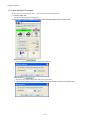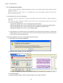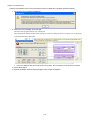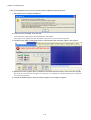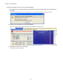
1
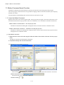
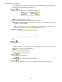
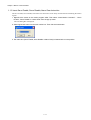
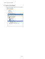
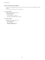
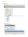
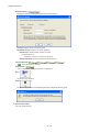
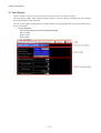
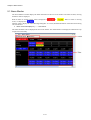
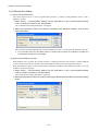
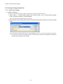
Engineering Tool for MP2000 Series Machine Controller
MPE720 Version 6
USER'S MANUAL
New Features of Version 6.04
Contents
Chapter 1 Motion Command Assist Function .............................................1-1
1.1 Motion Command Assist Function.......................................................... 1-2
1.1.1 Insert the Motion Command ....................................................................1-2
( 1 ) Input Motion Instruction..........................................................................1-2
1.1.2 Insert Servo Enable, Servo Disable, Alarm Clear Instruction .................1-4
Chapter 2 System Sub-window ..................................................................2-1
2.1 System Sub-window............................................................................... 2-2
Chapter 3 Test Run .....................................................................................3-1
3.1 Test Run.................................................................................................. 3-2
3.1.1 Test Run Procedure .................................................................................3-2
3.2 Servo Enable, Servo Disable ................................................................. 3-5
3.2.1 Servo Enable............................................................................................3-5
3.2.2 Servo Disable...........................................................................................3-5
3.3 Jog Operation ......................................................................................... 3-6
( 1 ) Set the speed reference ........................................................................3-6
3.3.1 Jog Forward .............................................................................................3-7
3.3.2 Jog Reverse .............................................................................................3-7
3.4 Step Operation........................................................................................ 3-8
3.4.1 Step Operation Procedure .......................................................................3-9
Chapter 4 Axis Monitor................................................................................4-1
4.1 Axis Monitor ............................................................................................ 4-2
4.2 Axis Monitor Display ............................................................................... 4-3
4.2.1 Toolbar......................................................................................................4-3
4.2.2 Circuit and Axis Display ...........................................................................4-3
( 1 ) Circuit Display ........................................................................................4-3
( 2 ) Axis Display............................................................................................4-3
4.2.3 Status Display ..........................................................................................4-4
( 1 ) Ready, Enabled......................................................................................4-4
( 2 ) Alarm, Warning.......................................................................................4-4
( 3 ) Profile Complete, In Position .................................................................4-4
( 4 ) Motion Command...................................................................................4-4
4.2.4 Monitor Parameter Display ......................................................................4-5
( 1 ) Monitoring the Monitor Parameters .......................................................4-5
Chapter 5 Alarm Monitor .............................................................................5-1
5.1 Alarm Monitor ......................................................................................... 5-2
5.1.1 Alarm Monitor Display..............................................................................5-3
( 1 ) Toolbar....................................................................................................5-3
( 2 ) Status......................................................................................................5-3
( 3 ) Show, Hide the Circuit............................................................................5-3
5.1.2 When Alarm, Warning Occurs .................................................................5-4
( 1 ) Alarm, Warning Information ...................................................................5-5
Chapter 6 Additional Function of Compile Options.....................................6-1
6.1 Additional Function of Compile Options ................................................. 6-2
Chapter 7 Troubleshooting..........................................................................7-1
7.1 Troubleshooting ...................................................................................... 7-2
7.2 Troubleshooting Flow ............................................................................. 7-3
7.2.1 Start Troubleshooting ...............................................................................7-3
7.2.2 Troubleshooting Details ...........................................................................7-4
( 1 ) An operation error occurs in the program..............................................7-4
( 2 ) I/O error occurs ......................................................................................7-8
7.2.3 Complete the Troubleshooting................................................................710
7.3 Error Codes .......................................................................................... 7-11
Chapter 8 Communications Setting ............................................................8-1
8.1 Communication Setting .......................................................................... 8-2
8.2 Connect Using Ethernet ......................................................................... 8-2
8.2.1 Computer Setting .....................................................................................8-2
( 1 ) Setting the IP Address ...........................................................................8-2
8.2.2 Ethernet Port Setting................................................................................8-5
( 1 ) How to Set an Ethernet Port..................................................................8-5
( 2 ) How to Set an Ethernet (LP) Port..........................................................8-5
8.3 Connect Using Serial Port ...................................................................... 8-7
8.3.1 Serial Port Settings ..................................................................................8-7
( 1 ) Setting of Serial Port ..............................................................................8-7
Chapter 1 Motion Command Assist
Chapter 1
Motion Command Assist Function
This chapter describes the "motion command assist function".
1.1 Motion Command Assist Function................................................... 1-2
1.1.1 Insert the Motion Command ....................................................................... 1-2
1.1.2 Insert Servo Enable, Servo Disable, Alarm Clear Instruction..................... 1-4
1-1
Chapter 1 Motion Command Assist
1.1 Motion Command Assist Function
The Motion Command Assist Function helps to input motion instructions when creating the motion program.
The motion program is described with a text-type Motion Language. Motion instructions should be input complying
with their own format.
Using the Motion Command Dialog Box, motion instructions will be easier to input.
1.1.1 Insert the Motion Command
Right-click the mouse in the motion program editor. The pop-up menu will appear. The motion instructions can be
selected and inserted from the pop-up menu. There are two methods to access the Motion Command Assist Function.
● Select “Motion command assist...” from the pop-up menu :
The Motion Command Assist Dialog Box is displayed. Select an instruction from the "command" column.
● Select “Insert motion command” – “Instruction” from the pop-up menu :
The Motion Command Assist Dialog Box is displayed. Select a motion instruction from the pop-up menu and it
is displayed in the "command" column.
( 1 ) Input Motion Instruction
1. Right-click the mouse in the motion program editor and select “Insert motion command” from the pop-up
menu.
The Motion Command Assist Dialog Box is displayed.
2. Complete all settings and click the Insert button.
The following two types of dialog boxes appear.
)
Select Command (
When clicking , the instructions which can be inserted are displayed. Select the instruction to be inserted.
)
Motion instruction Format (
The format of the selected instruction is displayed.
Number of Axes (
)
1-2
Chapter 1 Motion Command Assist
Set the number of controlled axes. When the number of axes of selected instruction is a fixed number, the
fixed number is displayed automatically and shown in gray.
)
Refresh (
Click the button to update the Motion Command Assist Dialog Box.
Setting the arguments (
)
The arguments of each motion instruction are displayed. Set the “axis name” and the “setting value” in the
table.
Arguments: The argument names are displayed.
Axis: Set the logical axis name which is defined in the "group definition".
Setting value: The constant and the register number can be input. If the setting value can be omitted,
"Optional" is displayed as default.
Unit: The unit of each argument is displayed.
is displayed. The tool tip help is displayed when the
When the units are not set,
mouse pointer is held over the unit. Set the unit according to the instruction.
Program code (
)
This program code is displayed when the motion instruction does not need the "axis name" and "setting
value".
)
Comment (
Comment column (
)
If "Comment" is selected, it is possible to add and edit comments in the "Comment column" for each
instruction. If not, "Comment column" is shown in gray.
Insert (
)
Click the button to insert the instruction.
Close (
)
Click the button to close the Motion Command Assist Dialog Box.
Help (
)
Click the button to display the "Machine Controller MP2200/MP2300 Motion Module User's Manual".
1-3
Chapter 1 Motion Command Assist
1.1.2 Insert Servo Enable, Servo Disable, Alarm Clear Instruction
The Servo Enable, Servo Disable, and Alarm Clear instruction can be easily inserted without considering the motion
register.
1. Right-click the mouse in the motion program editor. Then select “Insert Motion Command” – “Servo
Enable”, “Servo Disable” or “Alarm Clear” from the pop-up menu.
The Axis Dialog Box is displayed.
2. Select logical axis name from the Axis combo box. Then click the Insert button.
3. The instruction (Servo Enable, Servo Disable or Alarm Clear) is inserted at the cursor position.
1-4
Chapter 2 System Sub-window
Chapter 2
System Sub-window
This chapter describes the System Sub-window.
2.1 System Sub-window ........................................................................ 2-2
2-1
Chapter 2 System Sub-window
2.1 System Sub-window
The System Sub-window manages the following functions.
● Module configuration
● Axis configuration
- Test Run
- Axis Monitor
- Alarm Monitor
- Motion Parameter List
2-2
Chapter 3 Test Run
Chapter 3
Test Run
This chapter describes how to use the Test Run function.
3.1 Test Run........................................................................................... 3-2
3.1.1 Test Run Procedure .................................................................................... 3-2
3.2 Servo Enable, Servo Disable........................................................... 3-5
3.2.1 Servo Enable .............................................................................................. 3-5
3.2.2 Servo Disable.............................................................................................. 3-5
3.3 Jog Operation .................................................................................. 3-6
3.3.1 Jog Forward................................................................................................ 3-7
3.3.2 Jog Reverse................................................................................................ 3-7
3.4 Step Operation................................................................................. 3-8
3.4.1 Step Operation Procedure .......................................................................... 3-9
3-1
Chapter 3 Test Run
3.1 Test Run
The Test Run function is for checking if the machine controller can operate an axis. It has three functions.
- Servo Enable, Servo Disable: Enable or Disable the specified axis.
- JOG: Jogs the specified axis with specified speed and direction.
- STEP: Runs the specified axis a specified distance.
The following two functions are implemented for monitoring.
- Axis Monitor: Monitors the status of each axis.
- Alarm Monitor: Monitors the "Alarm information" of all axes in one screen.
♦ The Test Run function can be operated when the target axis has the following status.
Motion Controller
Axis
Operation Ready
SVB built-in CPU
Servo
SVB-01
Inverter
Servo Ready
Motion Command
Response Code
ON
ON
NOP
-
ON
NOP
SVA-01
ON
ON
NOP
SVR
ON
-
NOP
PO-01
ON
-
NOP
The Test Run function may not work correctly when a motion program or sequence program operates the
axis.
3.1.1 Test Run Procedure
1. Double-click the Test Run Folder in the System Sub-window.
A Test Run warning window will be displayed.
2. Confirm the contents. Then click the Agree button.
The Test Run Window and Axis Dialog Box is displayed.
3-2
Chapter 3 Test Run
3. Select the target axis from the Axis Dialog Box. Then click the OK button.
The following message is displayed.
4. The selected Axis name is displayed in the right side of the “Axis...” button when clicking the “Yes” button.
♦ The Test Run function can operate only one axis at a time.
Axis monitor (
)
The Axis Monitor Window is displayed in the Main Window.
)
Alarm monitor (
The Alarm Monitor Window is displayed in the Main Window.
Update (
)
Updates the display of the Test Run Window.
3-3
Chapter 3 Test Run
)
Axis (
The Axis Dialog Box is displayed.
Status (
/
The status of the axis is displayed.
Enable (
)
)
Click the button to enable the axis.
Disable (
)
Click the button to disable the axis.
Monitor Status (
/
/
The operating status of the monitor will be displayed.
Monitor (
)
The Alarm Warning Dialog Box is displayed.
3-4
)
Chapter 3 Test Run
3.2 Servo Enable, Servo Disable
The axis can be enabled and disabled with this function. The status of the axis can also be monitored in the Test Run
Dialog Box.
The way to operate and monitor the axis is described below.
3.2.1 Servo Enable
Enabling the axis and monitoring the status.
1. Click the Enable button.
The axis is enabled.
Axis status is changed to "Enabled".
The operation of Jog and Step becomes available.
3.2.2 Servo Disable
Disabling the axis and monitoring the status.
1. Click the Disable button.
The axis is disabled.
The status is changed to "Disabled".
Jog and Step cannot be used.
3-5
Chapter 3 Test Run
3.3 Jog Operation
The Jog operation is a function to run the forward or reverse direction of the axis. The running speed can be set in the
Speed reference Dialog Box.
Jog is available only while the axis is enabled.
The axis will run while the Forward or Reverse button is pressed. The axis will stop when the Forward or Reverse
button is released.
)
Speed reference (
The Speed reference Dialog Box is displayed, and the running speed (speed reference) is set in the dialog box.
Forward (
)
The axis runs forward.
Reverse (
)
The axis runs reverse.
( 1 ) Set the speed reference
1. Click the Speed reference button.
Speed reference Dialog Box is displayed.
2. Input speed reference. Then click the Set button.
♦ When the unit is not set, the following dialog box is displayed. Click the Open button to set the unit.
3-6
Chapter 3 Test Run
3.3.1 Jog Forward
The axis runs forward while the button is held down.
1. Hold down the Forward button with the mouse.
The axis runs forward.
2. Release the button.
The axis stops.
3.3.2 Jog Reverse
The axis runs reverse while the button is held down.
1. Hold down the Reverse button with the mouse.
The axis runs reverse.
2. Release the button.
The axis stops.
3-7
Chapter 3 Test Run
3.4 Step Operation
The step operation moves the axis a specified distance and then stops.
The axis starts moving when the Run button is clicked. Motion can be aborted with the Stop button.
The step operation can also repeat round trip motion several times.
The step operation operates under the following conditions.
● Servo is enabled.
● The speed reference and step distance must be set.
The "---" is displayed by default. If the Forward Reverse button is operated before setting them, the following
error message is displayed.
● The unit for speed reference and step distance must be set.
The unit of speed reference and step distance is related to some fixed parameters. If changing the unit of one, the
unit of the other is also changed.
The following error message is displayed if the unit is not set. To set the unit, click the Open button.
3-8
Chapter 3 Test Run
3.4.1 Step Operation Procedure
Please refer to "3.2 Servo Enable, Servo " to learn how to enable or disable servo.
1. Click the “Step” Tab.
The Step Setting Dialog Box is displayed.
2. Click the “Speed reference”, “Step distance” and “Direction setting” button and set them.
)
Speed reference (
Display Speed reference Dialog Box and set speed reference.
)
Step distance (
Display the Step distance Dialog Box and set the step distance.
♦ When the Step distance unit is not set, a fixed parameter of the Motion module is automatically read.
3-9
Chapter 3 Test Run
)
Direction setting (
Display the Direction Setting Dialog Box and set the direction.
Direction: Set the direction for first motion.
Repetitive running: Check it for repeat operation.
Repeat time: Set the number of times to repeat.
i.e. Repeat time is 2.
Forward -> Reverse -> Forward -> Reverse.
Repeat stop time: Set the interval time between motion.
Forward Reverse (
/
" shows the direction of motor.
"
,
/
)
)
Repeat time (
"Current repeat time/ Setting repeat time" is displayed.
Run (
)
To start the step operation.
Stop (
)
To stop the step operation. The following message is displayed when stopped.
3. Click the Run button.
The step operation starts.
3 - 10
Chapter 4 Axis Monitor
Chapter 4
Axis Monitor
This chapter describes how to use the Axis Monitor.
4.1 Axis Monitor ..................................................................................... 4-2
4.2 Axis Monitor Display ........................................................................ 4-3
4.2.1 Toolbar ........................................................................................................ 4-3
4.2.2 Circuit and Axis Display .............................................................................. 4-3
4.2.3 Status Display ............................................................................................. 4-4
4.2.4 Monitor Parameter Display ......................................................................... 4-5
4-1
Chapter 4 Axis Monitor
4.1 Axis Monitor
The axis monitor is a function to monitor the status of each axis in the "Axis Monitor" window.
The status (Ready, Enable, Alarm, Warning, Profile Complete, In Position, Motion Command) and other extended
monitoring parameters can be monitored.
The axis monitor updates when displayed in the Main Window. Scrolling displays other axes and parameters which
are out of the window.
♦ The axes displayed:
SVB: The axes which are connected via MECHATROLINK.
SVA-01: 2 axes.
PO-01: 4 axes.
SVR: 16 axes.
4-2
Chapter 4 Axis Monitor
4.2 Axis Monitor Display
The display of the Axis Monitor Window is described below.
4.2.1 Toolbar
Circuit (
Monitoring the selected circuit.
)
Monitor type (
/
/
The update cycle can be chosen from "High Speed, Normal Speed, Low Speed".
)
Monitoring (
/
Click the button to select stop or start monitoring.
Alarm monitor (
)
Click the button to display the Alarm Monitor window.
Refresh (
)
Click the button to update the Axis Monitor window.
4.2.2 Circuit and Axis Display
( 1 ) Circuit Display
The motion module number (SVB, SVA, PO-01, SVR) of the axis and module name are displayed.
( 2 ) Axis Display
The axis name and the product type of axis are displayed.
4-3
)
Chapter 4 Axis Monitor
4.2.3 Status Display
The status of the Ready, Enable, Alarm, Warning, Profile Complete, In Position and Motion Command are displayed.
( 1 ) Ready, Enabled
The status is displayed.
Ready (
/
Enabled (
/
) : The status if the axis is ready to operate.
) : The status if the axis is enabled.
( 2 ) Alarm, Warning
The status of the alarm and warning are displayed.
[Alarm, warning status]
No Alarm (
) : No alarm or warning.
Alarm (
) : Alarm has occurred.
Warning (
) : Warning has occurred.
Clicking the "status" displays the Alarm Warning Dialog Box. Details of the alarm and warning are displayed. Refer
to "Chapter 5: Alarm Monitor" for more information on the Alarm/Warning monitoring function.
( 3 ) Profile Complete, In Position
The status of Profile Complete and In Position are displayed. When Profile Complete or In Position signal is ON, the
lamp is displayed in blue.
Profile Complete (
/
) : The status of the Profile Complete.
In Position (
/
) : The status of the In Position.
( 4 ) Motion Command
The status of the motion command response code is displayed. The background is displayed in blue except "---"
(NOP).
4-4
Chapter 4 Axis Monitor
4.2.4 Monitor Parameter Display
The monitor parameters are displayed. The displayed parameters are chosen by selecting from the list or inputting the
register number (Only I/O).
In default, Machine coordinate feedback position (APOS), Position error (PERR), Feedback speed, and Feedback
torque/ thrust are displayed. Eight parameters can be displayed at the same time.
The selection of displayed parameters is saved in the project file. Therefore, when opening the Axis Monitor window
again, the same parameters will be displayed.
( 1 ) Monitoring the Monitor Parameters
).
1. Click the Monitor Parameter button (
The Monitor Parameter Dialog Box is displayed.
2. Select a parameter from the combo box or input a register number (Only I/O) directly.
Monitor parameters which are selectable from the combo box
Monitor Parameter
Register
Unit
Machine coordinate target position (TPOS)
ILxx0E
Reference unit
Target position (CPOS)
ILxx10
Reference unit
Machine coordinate system position (MPOS)
ILxx12
Reference unit
Machine coordinate feedback position (APOS)
Machine coordinate latch position (LPOS)
ILxx16
ILxx18
Reference unit
Reference unit
Position error (PERR)
ILxx1A
Reference unit
POSMAX number of turns
ILxx1E
[rev]
Speed reference output monitor
ILxx20
[pulse/sec]
Feedback speed
Feedback torque/ thrust
3. Click the OK button.
The monitor parameters are displayed.
ILxx40
Speed unit selection
ILxx42
Torque unit selection
4-5
Chapter 5 Alarm Monitor
Chapter 5
Alarm Monitor
This chapter describes how to use the Alarm Monitor.
5.1 Alarm Monitor................................................................................... 5-2
5.1.1 Alarm Monitor Display................................................................................. 5-3
5.1.2 When Alarm, Warning Occurs .................................................................... 5-4
5-1
Chapter 5 Alarm Monitor
5.1 Alarm Monitor
The Alarm Monitor window displays the alarm information of all axes in one window. The status of alarm, warning
and alarm code are displayed.
When an alarm or warning occurs, status is displayed as
or
. When no alarm or warning
.
occurs, it is displayed as
Clicking "status" displays the Alarm Warning Dialog Box. As a result, detailed information of the alarm and warning
can be confirmed.
♦ All the monitor data displays by “-----" when off-line.
The status and alarm code are displayed in each circuit number. The Alarm Monitor can display the information of up
to eight axes horizontally.
5-2
Chapter 5 Alarm Monitor
5.1.1 Alarm Monitor Display
( 1 ) Toolbar
In the toolbar, there are two icons to refresh manually and start/stop monitoring.
Manually refresh (
)
Alarm and warning information in the Alarm Monitor window is updated manually.
♦ The Alarm Monitor Window is not refreshed automatically.
Monitoring (
)
/
Click the button to stop or start the monitoring.
( 2 ) Status
When an alarm or warning occurs, the status of the alarm or warning is displayed as shown below.
Alarm (
) : Alarm is occurring.
Warning (
) : Warning is occurring.
No Alarm (
) : No alarm or warning.
( 3 ) Show, Hide the Circuit
The monitoring data of each circuit can be shown or hidden by clicking the circuit number. As a result, only selected
axes can be displayed.
i.e. Show
i.e. Hide
5-3
Chapter 5 Alarm Monitor
5.1.2 When Alarm, Warning Occurs
Click the status in the Alarm Monitor window. The Alarm/ Warning Dialog Box is displayed.
Clicking the "Help" button displays detailed information of the alarm or warning. Correct the alarm by checking
"help". Then click the Alarm Clear button to reset the alarm.
Axis name (
)
"Axis number", "comment" and "product type" are displayed in order.
Alarm, warning name (
The Alarm or Warning name is displayed.
Alarm clear (
)
)
To clear the alarm.
Help (
)
The description of the occurring alarm in the manual "Machine Controller MP2200/MP2300 Motion Module
User's Manual" is displayed.
Refresh (
)
To update the Alarm, Warning Dialog Box.
)
Alarm, Warning (
The BIT number, the parameter name, and the status are displayed.
Close (
)
To close the Alarm, Warning Dialog Box.
( 1 ) Alarm, Warning Information
All alarms and warnings are displayed in the Alarm, Warning display Dialog Box.
5-4
Chapter 6 Additional Function of Compile Options
Chapter 6
Additional Function of Compile Options
This chapter describes an additional function of compile options.
6.1 Additional Function of Compile Options .......................................... 6-2
6-1
Chapter 6 Additional Function of Compile Options
6.1 Additional Function of Compile Options
The ladder program "Compile Options" can be set without displaying the ladder program in this version or later.
Select "Ladder" – "General" from the tree in the Environment Setting Dialog Box and the Compile Option settings
are displayed.
● Program
Create new CP ladder
When "Use" is selected, "Create new CP ladder" is displayed in Ladder Sub-window popup menus.
● Compile Option
The option for compiling the ladder program is selected. The Compile Option can be set without displaying the
ladder program.
Enable Multiple Coil Check:
When "Enable" is selected, duplicate coils in the target program are checked during the compile.
Compile to Ver.5 Compatible:
When "Enable" is selected, ladder programs compiled with MPE720 version 6 can be displayed and edited
with MPE720 version 5 (Version 5.34 or later).
6-2
Chapter 7 Troubleshooting
Chapter 7
Troubleshooting
This chapter describes how to use the System Monitor function to find errors in the program.
7.1 Troubleshooting ............................................................................... 7-2
7.2 Troubleshooting Flow ...................................................................... 7-3
7.2.1 Start Troubleshooting.................................................................................. 7-3
7.2.2 Troubleshooting Details .............................................................................. 7-4
7.2.3 Complete the Troubleshooting....................................................................710
7.3 Error Codes ................................................................................... 7-11
7- 1
Chapter 7 Troubleshooting
7.1 Troubleshooting
Troubleshooting is a function to analyze problems such as the error, battery alarm, scan time etc.
When an error occurs, the message referencing the error is displayed in the System Monitor Sub-window.
Click the message "The alarm occurred. Please click with the mouse and execute the troubleshooting" to begin the
troubleshooting.
It is possible to analyze the error in the ladder program, motion program and sequence program.
Also, an I/O module error can be detected. There are two types of I/O errors.
- Station Error
This type of error occurs when the controller cannot communicate with network I/O because of the
disconnection of wiring or protocol differences.
- I/O Error
i.e. The I/O module has a blown fuse.
7- 2
Chapter 7 Troubleshooting
7.2 Troubleshooting Flow
7.2.1 Start Troubleshooting
1. When an error occurs, the System Monitor Sub-window automatically appears and the alarm is
displayed in the status area.
♦ The System Monitor can be configured in the Environment Setting Dialog Box. Refer to “( 2 ) Pop-up Display When
an Error Is Detected" in "MPE720 Version 6 User's Manual 6.2.5 System Monitor" for more information.
2. Click the message, "The alarm occurred. Please click with the mouse and execute the troubleshooting."
3. The error message describing the alarm is displayed.
♦ The details of the error message and the operation method for troubleshooting after step 3 are different depending
on the type of the error.
Operation error; refer to "7.2.2 ( 1 ) An operation error occurs in the program".
I/O error; refer to "7.2.2 ( 2 ) I/O error occur".
7- 3
Chapter 7 Troubleshooting
7.2.2 Troubleshooting Details
The way to analyze a problem is different depending on the type of error: ladder program, motion program, sequence
program, or I/O error.
When an operation error occurs, refer to "( 1 ) An operation error occurs in the program". When an I/O error occurs,
refer to "( 2 ) I/O error occurs".
( 1 ) An operation error occurs in the program
The way to analyze an operation error occurring in the ladder program, motion program, or sequence program is
described.
The analysis procedure is different according to where the error occurs. (The following example is the case if the
error occurs in the ladder program.)
・ [case a] The operation error occurs in the program (except functions).
・ [case b] The operation error occurs in the function which is called from a program (except functions).
・ [case c] The operation error occurs in a function which is called from another function.
・ [case d] The operation error occurs in an uncertain program.
♦ Error information is not cleared even if the cause displayed in the System Monitor Sub-window is corrected when
multiple operation errors occur at the same time. In this case, error information might be incorrect. Please clear last
error information by clicking the Reset button.
[case a] The operation error occurs in the program (except functions).
1. The following error message is displayed.
2. Confirm the error message. Then click OK button.
The name of the program with the error is displayed.
♦ A pop-up is displayed when the mouse is held over the status. Error information can be confirmed at a glance.
3. Correct the problem.
4. Compile the ladder program. Save the motion program or the sequence program.
7- 4
Chapter 7 Troubleshooting
[case b] The operation error occurs in the function which is called from a program (except functions).
1. The following error message is displayed.
2. Confirm the error message. Then click OK.
The name of the program with the error is displayed.
The program name and step number which specify the instruction calling the function with the error are displayed
in the System Monitor Sub-window.
♦ A pop-up is displayed when the mouse is held over the status. Error information can be confirmed at a glance.
3. Correct the problem.
4. Compile the ladder. Save the motion program or the sequence program.
7- 5
Chapter 7 Troubleshooting
[case c] The operation error occurs in a function which is called from another function.
1. The following error message is displayed.
2. Confirm the error message. Then click OK.
Error information is displayed in the System Monitor Sub-window.
The program is not displayed because the location where the error occurs cannot be specified.
3. Find the function which is calling the function. Then find the FUNC instruction object in the program.
4. Display the function program which is called from the FUNC instruction object. Then correct the program.
Specify the type of instruction causing the error based on error information. Then find the instruction causing the
error and correct program.
5. Compile the ladder program. Save the motion program or the sequence program.
7- 6
Chapter 7 Troubleshooting
[case d] The operation error occurs in an uncertain program.
1. The following error message is displayed when MPE720 version 6 assesses that it is not the latest error
information.
i.e. When the program which has been making the error is deleted, MPE720 Version 6 assesses as above.
2. Confirm the error message. Then click the OK Button.
Old error information may be displayed in the System Monitor Sub-window status.
3. Click Status to clear the error information.
Error information will be updated.
7- 7
Chapter 7 Troubleshooting
( 2 ) I/O error occurs
1. When an error occurs on the I/O module mounted to the machine controller, the following error message
is displayed.
2. Confirm the error message. Then click the OK button.
3. Confirm the module information. Then display Module Configuration.
7- 8
Chapter 7 Troubleshooting
4. Display the Module Configuration with the I/O configuration that has an error.
The I/O which has generated an error is indicated on the status (STS) tab.
♦ Status is displayed as a hexadecimal number.
5. Save the Module Configuration.
7- 9
Chapter 7 Troubleshooting
7.2.3 Complete the Troubleshooting
When correction of the error is finished and no other errors occur, the System Monitor Sub-window displays
normally.
♦ If the program is not modified correctly or another error remains, repeat the procedure "7.3 Error Codes" and
analyze the error again.
7- 10
Chapter 7 Troubleshooting
7.3 Error Codes
The following table shows the error codes that can be detected by the System Monitor.
Error Code
Error Classification
Error Code
Error Classification
Integer operation: Underflow
LAG error
0x01
0x70
Integer operation: Overflow
LLAG error
0x02
0x71
Integer operation: Division error
FGN error
0x03
0x72
Double integer operation: Underflow
IFGN error
0x09
0x73
Double integer operation: Overflow
LAU error
0x0A
0x74
Double integer operation: Division error
SLAU error
0x0B
0x75
Integer storage: Non-numeric error
FGN error
0x10
0x76
Integer storage: Underflow
IFGN error
0x11
0x77
Integer storage: Overflow
SLAU error
0x12
0x7E
Real number storage: Underflow
BIN error
0x21
0x80
Real number storage: Overflow
BIN error
0x22
0x81
Real number operation: Division by zero
BCD error
0x23
0x82
Real number operation: Invalid operation
BCD error
0x30
0x83
Real number operation: Exponential underflow
PARITY error
0x31
0x84
Real number operation: Exponential overflow
PARITY error
0x32
0x85
Real number operation: Division error
SQRT error
0x33
0x86
Real number storage: Exponential underflow
SIN error
0x34
0x87
Real number operation: Stack error
COS error
0x35
0x88
SQRT error
ATAN error
0x40
0x89
SIN error
IN error
0x41
0x8A
COS error
OUT error
0x42
0x8B
TAN error
INR error
0x43
0x8C
ASIN error
OUTR error
0x44
0x8D
ACOS error
INS error
0x45
0x8E
ATAN error
OUTS error
0x46
0x8F
EXP error
ROTL error
0x47
0x90
LN error
ROTR error
0x48
0x91
LOG error
MOVB error
0x49
0x92
DZA error
MOVW error
0x4A
0x93
DZB error
SETW error
0x4B
0x94
LIMIT error
XCHG error
0x4C
0x95
PI error
LIMIT error
0x4D
0x96
PD error
LIMIT error
0x4E
0x97
PID error
DZA error
0x4F
0x98
LAG error
DZA error
0x50
0x99
LLAG error
DZB error
0x51
0x9A
FGN error
DZB error
0x52
0x9B
IFGN error
PWM error
0x53
0x9C
LAU error
SFC error
0x54
0x9D
SLAU error
SHFTL error
0x55
0x9E
REM error
SHFTR error
0x56
0x9F
RCHK error
BEXTD error
0x57
0xA0
BSRCH error
BPRESS error
0x58
0xA1
SORT error
SORT error
0x59
0xA2
PI error
QSORT error
0x6D
0xA3
PD error
SORT error
0x6E
0xA4
PID error
QSORT error
0x6F
0xA5
7- 11
Chapter 7 Troubleshooting
Error Code
Error Classification
0xA6
RCHK error
0xA7
RCHK error
0xA8
COPYW error
0xA9
ASCII error
0xAA
BINASC error
0xAB
0xAC
ASCBIN error
BRCH error
0xAD
BSRCH error
0xAE
TMADD error
0xAF
TMSUB error
0xB1
SPEND error
0xC0
0xC1
TBLBR error
TBLBW error
0xC2
TBLSRL error
0xC3
TBLSRC error
0xC4
TBLCL error
0xC5
TBLMV error
0xC6
0xC7
QTBLR error
QTBLRI error
0xC8
QTBLW error
0xC9
QTBLWI error
0xCA
QTBLCL error
0xE0
MSEE error
7- 12
Chapter 8 Communications Setting
Chapter 8
Communications Setting
This chapter describes the communication setting to connect MPE720 version 6 to the
Machine Controller.
8.1 Communication Setting ................................................................... 8-2
8.2 Connect Using Ethernet .................................................................. 8-2
8.2.1 Computer Setting........................................................................................ 8-2
8.2.2 Ethernet Port Setting .................................................................................. 8-5
8.3 Connect Using Serial Port ............................................................... 8-7
8.3.1 Serial Port Settings ..................................................................................... 8-7
8-1
Chapter 8 Communications Setting
8.1 Communication Setting
The following communication port can be used to connect.
- Ethernet (10 MB Ethernet, 100 MB Ethernet)
- Serial
- MP2100 BUS
- USB
8.2 Connect Using Ethernet
The following setting is necessary for communication using an Ethernet connection via CP-218 communications port
on the 218IF-01 Module or 218IFA/B Module. There are two types of Ethernet communication hardware: the
218IF-01 Module (10 MB Ethernet) and the 218IFA/B Module(100 MB Ethernet).
8.2.1 Computer Setting
( 1 ) Setting the IP Address
The IP address of the computer must be set before setting the Ethernet connection. The following description shows
how to set the IP address.
1. Click the Start button. Then select “Settings” – “Control Panel” from the “Start Menu”.
Click the “Internet Options” icon in “Control Panel”.
The Internet Properties Dialog Box is displayed.
2. Select the Connections Tab. Then click the LAN Settings button.
The "Local Area Network (LAN) Settings" Dialog Box is displayed.
8-2
Chapter 8 Communications Setting
3. Confirm that the “Automatically detect settings” check box is not selected. Then click OK to close the
dialog box.
4. For Windows XP, click the Start button and select “Settings” – “Control Panel”. Then click the “Network
Connections” Icon in the “Control Panel”.
For Windows 2000, click the Start button and select “Settings” – “Control Panel”. Then click the “Network
and Dial-up Connections” Icon in the “Control Panel”.
The "Network Connections window" on Windows XP or the "Network and Dial-up Connections window" on
Windows 2000 is displayed.
5. For Windows XP, select “Local Area Connection”. Then click “Change settings of this connection” in the
“Network Tasks” field.
For Windows 2000, double-click the “Local Area Connection” icon.
The "Local Area Connection Properties" Dialog Box is displayed.
6. Select the “Internet Protocol (TCP/IP)” check box in the “General” tab. Then click the Properties button.
The "Internet Properties (TCP/IP)" Dialog Box is displayed.
8-3
Chapter 8 Communications Setting
7. Select “Use the following IP address”. Then enter “192 168 1 2” for the “IP address” and “255 255 255 0”
for the “Subnet mask”.
8. Click OK to close the dialog box.
8-4
Chapter 8 Communications Setting
8.2.2 Ethernet Port Setting
( 1 ) How to Set an Ethernet Port
This section describes how to connect communications between a computer running MPE720 version 6 and a
Machine Controller.
1. Select “Online” – “Communications Setting” from the “Main Menu” or click “Communications Setting”
under “Controller (or Project)” in the “Start Window”.
The "Communications Setting Dialog Box" is displayed.
2. Select the logical port number to be used for connecting to the Machine Controller. Then click the
Connection button.
The Communication Setting Dialog Box is closed and MPE720 version 6 is connected to the Machine Controller.
♦ The Connection button and the Setting button are invalid while connected to the Machine Controller and
communication settings cannot be changed.
( 2 ) How to Set an Ethernet (LP) Port
When Ethernet (LP) is selected, the "Search Controller" is displayed. When the Search button is clicked, MPE720
version 6 searches the machine controller connected via Ethernet (LP) and the result is displayed in the list.
When the Machine Controller is selected from "Search Controller", IP address of the Machine Controller is set to the
IP address column automatically.
1. Select “Online” – “Communications Setting” from the “Main Menu” or click “Communications Setting”
under “Controller (or Project)” in the Start window.
The Communications Setting Dialog Box is displayed.
2. Select the logical port number to be used for connecting to the Machine Controller. Then click the Setting
button.
8-5
Chapter 8 Communications Setting
3. Click the Connection button.
The Communications Setting Dialog Box is closed and MPE720 version 6 is connected to the Machine Controller.
♦ The Connection button and the Setting button are invalid while connected to the Machine Controller, and
communication settings cannot be changed.
■ Confirm IP address by the following method when MPE720 cannot connect to the machine controller.
- Setting the Communication Port
1. Display the "Communication Setting" Dialog Box. Then click the Search button.
2. Machine controller name and IP address are displayed in the “Search Controller”.
3. Verify the IP address which is searched and input to IP address column. Then click the Connection button.
- Setting the Ethernet Port
Confirm if the port setting of the computer is correct. Refer to "( 1 ) Setting the IP Address".
8-6
Chapter 8 Communications Setting
8.3 Connect Using Serial Port
8.3.1 Serial Port Settings
( 1 ) Setting of Serial Port
This section describes the setting to connect to the Machine Controller using the serial port.
1. Select “Online” – “Communications Setting” from the Main Menu or click “Communications Setting”
under “Controller (or Project)” in the Start window.
The Communications Setting Dialog Box is displayed.
2. Select the logical port number to be used for connecting to the Machine Controller. Then click the Setting
button.
The Communications Setting Dialog Box is closed and MPE720 version 6 is connected to the Machine Controller.
♦ The Connection button and the Setting button are invalid while connected to the Machine Controller and
communication settings cannot be changed.
8-7