1
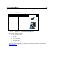
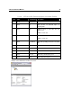
SCM Microsystems
Reference Manual – version 1.5
SCL3711
Multiprotocol contactless mobile reader
Reference manual
SCL3711 Multiprotocol Contactless mobile
Reader
© SCM Microsystems
Oskar-Messter-Strasse, 13
85737 Ismaning
Germany
Phone +49 89 9595 5000 • Fax +49 89 9595 5555
Document history
Date
Version
Description of change
16/02/2009
1.0
Initial version
06/03/2009
1.1
Review and update by product management
18/03/2009
1.2
Final review for release
01/04/2009
1.3
Update – added examples of APDU sequences for a few
commands + corrected a few typos
01/04/2009
1.4
Updates related to Driver version 1.04
29/10/2009
1.5
Updates related to Driver version 1.06
• Various editorial changes
• Installation procedure chapter updated
• Addition of T=CL user command description (§6.1.3)
• Addition of FELICA_PASSTHROUGH escape (§6.6.10)
Contact information
http://www.scmmicro.com/products-services/smart-card-readers-terminals/contactless-dualinterface-readers.html
For sales information, please email [email protected]
Table of Contents
1.
Legal information ............................................................................................................... 7
1.1.
Disclaimers..................................................................................................................... 7
1.2.
Licenses ......................................................................................................................... 7
1.3.
Trademarks .................................................................................................................... 7
2.
Introduction to the manual ................................................................................................. 8
2.1.
Objective of the manual ................................................................................................. 8
2.2.
Target audience ............................................................................................................. 8
2.3.
Product version corresponding to the manual ............................................................... 8
2.4.
Definition of various terms and acronyms...................................................................... 9
2.5.
References ................................................................................................................... 10
2.6.
Conventions ................................................................................................................. 11
3.
General information about SCL3711 ............................................................................... 12
3.1.
SCL3711 key benefits .................................................................................................. 12
3.2.
SCL3711 key features.................................................................................................. 12
3.3.
SCL3711 ordering information ..................................................................................... 13
3.4.
SCL3711 customization options................................................................................... 13
3.5.
Contactless communication principles and SCL3711 usage recommendations ......... 14
3.5.1. Power supply......................................................................................................... 14
3.5.2. Data exchange ...................................................................................................... 14
3.5.3. Recommendations ................................................................................................ 15
3.6. Applications .................................................................................................................. 16
3.6.1.
3.6.2.
4.
General ................................................................................................................. 16
Applications provided by SCM Microsystems....................................................... 16
SCL3711 characteristics.................................................................................................. 17
4.1.
SCL3711 high level architecture .................................................................................. 17
4.1.1. Block diagram ....................................................................................................... 17
4.1.2. Software architecture ............................................................................................ 17
4.2. Quick reference data .................................................................................................... 18
4.2.1.
4.2.2.
4.2.3.
5.
SCL3711 dimensions............................................................................................ 18
LED behavior ........................................................................................................ 18
Other data ............................................................................................................. 18
Software modules ............................................................................................................ 20
5.1.
Installation .................................................................................................................... 20
5.1.1. Command line parameters for installation ............................................................ 21
5.1.2. Command line parameters for un-installation. ...................................................... 21
5.2. Utilities.......................................................................................................................... 21
5.3.
Driver ............................................................................................................................ 22
5.3.1. SCL3711 listing..................................................................................................... 22
5.3.2. Supported operating systems ............................................................................... 22
5.3.3. PC/SC 2.0 compliant ATR .................................................................................... 23
5.4. Firmware ...................................................................................................................... 28
5.4.1.
5.4.2.
6.
Transport protocol ................................................................................................. 28
Automatic PPS ...................................................................................................... 28
Commands description .................................................................................................... 29
6.1.
Generic APDUs ............................................................................................................ 29
6.1.1. Get UID Command ............................................................................................... 29
6.1.2. Get DATA Command ............................................................................................ 30
6.1.3. T=CL user Command............................................................................................ 31
6.1.4. PASS_THROUGH command ............................................................................... 32
6.2. Set of APDU for contactless storage user tokens........................................................ 33
6.2.1. STORAGE_CARD_CMDS_READ_BINARY ........................................................ 33
6.2.2. STORAGE_CARD_CMDS_WRITE_BINARY ...................................................... 35
6.2.3. STORAGE_CARD_CMDS_LOAD_KEYS ............................................................ 37
6.2.4. STORAGE_CARD_CMDS_AUTHENTICATE...................................................... 38
6.2.5. STORAGE_CARD_CMDS_VALUE_BLOCK ....................................................... 40
6.3. Set of APDU for ISO/IEC 14443-4 user tokens ........................................................... 41
6.3.1. T=CL Command.................................................................................................... 41
6.4. MIFARE DESFire commands ...................................................................................... 42
6.5.
Set of APDU defined by SCM Microsystems ............................................................... 42
6.5.1. Commands for communicating with NFC Forum Tags Type 1............................. 42
6.5.2. Commands for communicating with NFC Forum Tags Type 2............................. 48
6.5.3. Commands for communication with NFC Forum Tags Type 3............................. 48
6.5.4. Commands for communicating with NFC Forum Tags Type 4............................. 50
6.6. Escape IOCTL’s supported in SCL3711 ...................................................................... 51
6.6.1.
6.6.2.
6.6.3.
6.6.4.
6.6.5.
6.6.6.
6.6.7.
6.6.8.
6.6.9.
6.6.10.
7.
READER_CNTLESS_GET_ATS_ATQB .............................................................. 51
READER_GET_CARD_TYPE_POLLING ............................................................ 52
READER_CNTLESS_SET_TYPE ........................................................................ 52
READER_CNTLESS_RF_SWITCH ..................................................................... 53
READER_ CNTLESS_DISABLE_PPS................................................................. 53
READER_ENABLE_DISABLE_848 ..................................................................... 54
READER_CNTLESS_BAUDRATE....................................................................... 54
READER_FORCE_BAUDRATE........................................................................... 55
READER_DISABLE_NAK_POLLING................................................................... 56
FELICA_PASSTHROUGH.................................................................................... 56
Annexes ........................................................................................................................... 57
7.1.
Annex A........................................................................................................................ 57
7.1.1. Status words table ................................................................................................ 57
7.1.2. Further information about PC/SC.......................................................................... 57
7.2. Annex B – Mechanical drawings .................................................................................. 58
SCL3711 REFERENCE MANUAL
1. Legal information
1.1.
Disclaimers
The content published in this document is believed to be accurate. SCM Microsystems does
not, however, provide any representation or warranty regarding the accuracy or completeness
of its content and regarding the consequences of the use of information contained herein. If this
document has the status “Draft”, its content is still under internal review and yet to be formally
validated.
SCM Microsystems reserves the right to change the content of this document without prior
notice. The content of this document supersedes the content of previous versions of the same
document. The document may contain application descriptions and/or source code examples,
which are for illustrative purposes only. SCM Microsystems gives no representation or warranty
that such descriptions or examples are suitable for the application that the reader may want to
use them for.
Should you notice problems with the provided documentation, please provide your feedback to
[email protected].
1.2.
Licenses
If the document contains source code examples, they are provided for illustrative purposes only
and subject to the following restrictions:
•
You MAY at your own risk use or modify the source code provided in the document
in applications you may develop. You MAY distribute those applications ONLY in
form of compiled applications.
•
You MAY NOT copy or distribute parts of or the entire source code without prior
written consent from SCM Microsystems.
•
You MAY NOT combine or distribute the source code provided with Open Source
Software or with software developed using Open Source Software in a manner that
subjects the source code or any portion thereof to any license obligations of such
Open Source Software.
If the document contains technical drawings related to SCM Microsystems products, they are
provided for documentation purposes only. SCM Microsystems does not grant you any license
to its designs.
1.3.
Trademarks
MIFARE is a registered trademark of NXP Semiconductors BV.
FeliCa is a registered trademark of Sony Corporation.
Jewel and Topaz are trademarks of Innovision Research and Technology Plc.
Windows is a registered trademark of Microsoft Corporation
7
SCL3711 REFERENCE MANUAL
2. Introduction to the manual
2.1.
Objective of the manual
This manual provides an overview of the hardware and software features of the SCL3711
multiprotocol mobile contactless reader, hereafter referred to as “SCL3711”.
This manual describes in details interfaces and supported commands available for developers
using SCL3711 in their applications.
2.2.
Target audience
This document describes the technical implementation of SCL3711.
The manual targets software developers. It assumes knowledge about 13.56 MHz contactless
technologies like ISO/IEC 14443 and commonly used engineering terms.
Should you have questions, you may send them to [email protected] .
2.3.
Product version corresponding to the manual
Item
Version
Hardware
0.2
Firmware
2.7.0
Driver
1.06
Installer
1.04
8
SCL3711 REFERENCE MANUAL
2.4.
9
Definition of various terms and acronyms
Term
Expansion
APDU
ATR
ATS
Byte
CCID
CID
CL
CLA
DFU
FeliCa™
Application Protocol Data Unit
Answer to Reset, defined in ISO7816
Answer to Select, defined in ISO14443
Group of 8 bits
Chip Card Interface Device
Card Identifier
Contactless
Class byte defined in ISO 7816
Device Firmware Upgrade
Sony contactless technology standardized in ISO18092, technology underlying the
NFC Forum tag type 3
Instruction byte defined in ISO7816
Innovision contactless technology, technology underlying the NFC Forum tag type
1
Light emitting diode
The ISO14443 Type A with extensions for security (NXP)
Not applicable
Node Address
NFC Data Exchange Format: data structure defined by the NFC Forum for NFC
Forum tags.
Near Field Communication
Group of 4 bits. 1 digit of the hexadecimal representation of a byte.
Example: 0xA3 is represented in binary as (10100011)b. The least significant
nibble is 0x3 or (0011)b and the most significant nibble is 0xA or (1010)b
Peer – to – Peer
Proximity Coupling Device
Personal Computer/Smart Card: software interface to communicate between a PC
and a smart card
Proximity Integrated Chip Card
Product ID
Protocol Parameter Selection
Distance coverage till ~10 cm.
Pseudo unique PICC identifier
Reserved for future use
Radio Frequency
Smart card reader controller ASIC from SCM Microsystems
Status word defined in ISO7816
Universal Serial Bus
Vendor ID
Binary notation of a number x, y, z ∈{0,1}
The byte value YY is represented in hexadecimal
INS
Jewel/Topaz
LED
MIFARE
NA
NAD
NDEF
NFC
Nibble
P2P
PCD
PC/SC
PICC
PID
PPS
Proximity
PUPI
RFU
RF
STC3
SW1 SW2
USB
VID
(xyz)b
0xYY
SCL3711 REFERENCE MANUAL
2.5.
10
References
Doc ref in
the manual
Description
Issuer
ISO/IEC
7816-4
Identification cards - Integrated circuit(s) cards
with contacts
Part 4: Interindustry commands for interchange
ISO/IEC 7816-4: 1995 (E)
Identification cards — Contactless integrated
circuit(s) cards — Proximity cards
Part 4: Transmission protocol ISO/IEC 144434:2001(E)
Information technology — Telecommunications
and information exchange between systems —
Near Field Communication — Interface and
Protocol (NFCIP-1) ISO/IEC 18092:2004(E)
NFCForum-TS-Type-1-Tag_1.0
ISO / IEC
NFC Forum
NFCForum-TS-Type-2-Tag_1.0
NFC Forum
NFCForum-TS-Type-3-Tag_1.0
NFC Forum
NFCForum-TS-Type-4-Tag_1.0
NFC Forum
Interoperability Specification for ICCs and
Personal Computer Systems v2.01
User manual of the NFC wrapper. This manual
is part of SCM’s Contactless SDK.
Specification for Integrated Circuit(s) Cards
Interface Devices 1.1
Universal Serial Bus Specification 2.0
PC/SC Workgroup
ISO/IEC
14443-4
ISO/IEC
18092
NFC Forum
tag type 1
NFC Forum
tag type 2
NFC Forum
tag type 3
NFC Forum
tag type 4
PC/SC
NFC
wrapper
CCID
USB
ISO / IEC
ISO / IEC
SCM Microsystems
USB-IF
USB-IF
SCL3711 REFERENCE MANUAL
2.6.
Conventions
Bits are represented by lower case ‘b’ where followed by a numbering digit.
Bytes are represented by upper case ‘B’ where followed by a numbering digit.
Example:
163 in decimal is represented
•
in hexadecimal as 0xA3
•
in binary as (10100011)b
The least significant nibble of 0xA3 is
•
0x3 in hexadecimal
•
(0011)b in binary
The most significant nibble of =xA3 is
•
0xA in hexadecimal
•
(1010)b in binary
11
SCL3711 REFERENCE MANUAL
12
3. General information about SCL3711
3.1.
SCL3711 key benefits
With its functional solid mechanical design that has no removable parts that you may loose,
SCL3711 is perfect for mobile uses.
While being slim, SCL3711 dimensions have been optimized to ensure best RF performance
possible with such a form factor.
The state of the art multi-protocol feature set of SCL3711 qualifies it to be used in a wide range
of applications such as payment, loyalty and ID schemes, or to enable devices with NFC
connectivity.
As a latest generation product, SCL3711 can be supported by SCM’s middleware that resides
above the PC/SC API and offers better portability of applications and abstraction of smart card
related details that need to be handled by applications developed on top of the PC/SC API.
3.2.
SCL3711 key features
•
•
Multi-protocol 13.56MHz contactless reader:
o
ISO14443 type A & B
o
MIFARE (Classic, DESFire, UL, UL-C, MIFARE PLUS)
o
FeliCa™
o
NFC Peer-to-peer communication will be available through driver upgrade
PC/SC v2.0 compliant
SCL3711 REFERENCE MANUAL
3.3.
SCL3711 ordering information
Item
Part number
SCL3711
905108
Contactless SDK
905124
3.4.
13
SCL3711 customization options
Upon request, SCM can customize:
•
The color of the casing
•
The logo
•
The product label
•
The USB strings
Terms and conditions apply, please contact your local SCM representative or send an email to
[email protected].
SCL3711 REFERENCE MANUAL
14
3.5.
Contactless communication principles and SCL3711
usage recommendations
1
SCL3711 is a contactless reader designed
to communicate with user tokens.
User tokens
2
User tokens are made of a contactless
integrated circuit card connected to an
antenna
Credit card sized smart card
•
Key fob
•
NFC mobile phone etc…
1
71
L3
•
SC
User tokens can take several form factors:
Communication between SCL3711 and user tokens uses magnetic field inductive coupling.
The magnetic field generated by SCL3711 has a carrier frequency of 13.56MHz.
3.5.1. Power supply
When the user token is put in the magnetic field of the reader, its antenna couples with the
reader and an induction current appears in the antenna thus providing power to the integrated
circuit. The generated current is proportional to the magnetic flux going through the antenna of
the user token.
3.5.2. Data exchange
The carrier frequency of the magnetic field is used as a fundamental clock signal for the
communication between the reader and the card. It is also use as a fundamental clock input for
the integrated circuit microprocessor to function.
To send data to the user token the reader modulates the amplitude of the field. There are
several amplitude modulation and data encoding rules defined in ISO/IEC 14443 and ISO/IEC
18092. The reader should refer to those standards for further details.
To answer to the reader, the integrated circuit card of the user token modulates its way of
loading (impedance) the field generated by the reader. Here also further details can be found in
ISO/IEC 14443 and ISO/IEC 18092.
1
In the ISO/IEC 14443 standard, the reader is called the proximity coupling device (PCD)
2
In the ISO/IEC 14443 standard, the user token is called proximity integrated chip card (PICC)
SCL3711 REFERENCE MANUAL
15
3.5.3. Recommendations
The communication between the reader and the user token is sensitive to the presence of
material or objects interfering with the magnetic field generated by the reader.
The presence of conductive materials like metal in the vicinity of the reader and the user token
can severally degrade the communication and even make it impossible. The magnetic field of
the reader generates Eddy or Foucault’s currents in the conductive materials; the field is
literally absorbed by that kind of material.
It is recommended for proper communication to avoid putting SCL3711 in
close proximity of conductive materials.
The presence of multiple user tokens in the field also interferes with the communication. When
several user tokens are in the field of the reader, load of the field increases which implies that
less energy is available for each of them and that the system is detuned. For this reason, SCM
Microsystems has implemented in its driver the support for 1 slot only.
It is recommended to present only one user credential at a time in front of
SCL3711.
The communication between the reader and the user token is sensitive to the geometry of the
system {reader, user token}. Parameters like the geometry and specially the relative size of the
reader and user token antennas directly influence the inductive coupling and therefore the
communication.
SCL3711 was primarily designed and optimized to function with user credentials of various
technologies having the size of a credit card.
It may happen that SCL3711 is not capable of communicating with extremely
large or extremely small antennas.
In order to optimize the coupling between the reader and the user token, it is
recommended to put both antennas as parallel as possible
In order to optimize transaction speed between the reader and the card it is
recommended to place the user token as close as possible to the reader. This
will increase the amount of energy supplied to the user credential which will
then be able to use its microprocessor at higher speeds
SCL3711 REFERENCE MANUAL
3.6.
16
Applications
3.6.1. General
SCL3711 is a transparent reader designed to interface a personal computer host supporting
PC/SC interface with 13.56MHz user tokens like public transport cards, contactless banking
cards, NFC forum tags, electronic identification documents – e.g. e-passports, e-ID cards,
driving licenses etc.
Those user tokens can have several form factors like credit cards, key fobs, NFC mobile
phones or USB dongles like SCT3511 or @MAXX Lite that SCM Microsystems markets.
SC
L3
71
1
SCL3711 itself handles the communication protocol but not the application related to the token.
The application-specific logic has to be implemented by software developers on the host.
3.6.2. Applications provided by SCM Microsystems
SCM Microsystems does not provide payment or transport applications.
SCM Microsystems provides a few applications for development and evaluation purposes that
can function with SCL3711. They are available within the software development kit. There are
many tools provided but the two main ones are:
•
The NFC forum tag reader/writer is a standalone application that enables the user to
read and write NFC forum compliant records into NFC forum compatible tags. It is an
easy to use tool to configure rapidly NFC forum tag demonstrations.
•
Smart card commander version 1.1 provides a module which for NFC forum tags that
parses and presents in XML format the content of the tag. Smart card commander
also contains powerful scripting functionality which can be very useful for developers
to develop and debug their applications.
SCL3711 REFERENCE MANUAL
17
4. SCL3711 characteristics
4.1.
SCL3711 high level architecture
4.1.1. Block diagram
The link between SCL3711 and the host to which it is connected is the USB interface providing
both the power and the communication channel.
SCL3711 is based designed around an NFC controller which handles the USB communication
to the host and the RF communication. This controller ensures the coding/decoding/framing
modulation/demodulation required for the RF communication.
The matching circuitry provides the transmission and receiver paths adaptation for the antenna
to function properly.
4.1.2. Software architecture
Applications can interface with the driver
directly through the PC/SC interface or
through the SCM proprietary interface to the
NFC wrapper.
The NFC wrapper simplifies the usage of
the different NFC Forum tags with the
SCL3711 and other SCM contactless
readers. It provides a unique API to
application developers, which enables them
to read and modify NDEF records without
further knowledge of the underlying
hardware
and
protocols.
Detailed
information about the NFC wrapper can be
found in SCM’s Contactless SDK.
Application
SCM API (for P2P and
extra services)
SCM’s NFC
wrapper
PC/SC v2.0 API (ADPU
from ISO/IEC 7816-4
and SCM defined)
Driver
Firmware
The SCL3711 driver implements PC/SC v2.0 API towards upper layers. The SCL3711 driver for
Windows platforms is based on the Windows Driver Framework (WDF) version 1.09.
SCL3711 REFERENCE MANUAL
4.2.
18
Quick reference data
4.2.1. SCL3711 dimensions
Item
Characteristic
Value
Weight
External
dimensions(mm)
Cable length
Default color
Default logo
10.2 Grams
65.4(L) x 24(W) x 10 (H)
NA
BLACK Textured Finish
SCM logo
SCL3711
Default label
Drawing with dimensions of the SCL3711 and accessories can be found in annex.
4.2.2. LED behavior
The LED behavior of the SCL3711 is given below.
SCL3711 states
LED Indication (GREEN)
After plug-in (no driver loaded)
Driver successfully loaded
User token arriving in the field
User token removed from the field
Suspend/hibernate/shutdown state
SCL3711 disabled
OFF
ON
One blink
ON, no specific visual indication
OFF
OFF
4.2.3. Other data
Parameter
Value/Description
DC characteristics
Low bus powered (SCL3711 draws power from USB bus)
Voltage: 5V
Max Current : 100mA
Suspend current : 260uA
Clock of the device
controller
RF carrier frequency
Modulation
Unloaded field strength
USB specification
Max 27.12MHz
13.56 MHz +/- 50 ppm
As defined in ISO/IEC 14443
1.5 A/m to 2.2 A/m ( Un-modulated RF on reader casing)
USB 2.0 FS Devise
SCL3711 REFERENCE MANUAL
USB Speed
Device Class
PID
VID
API
ID1 format tokens
supported
Maximum baud rate
Multiple PICC in field
Operating temperature
range
Operating humidity
range
Storage condition range
Certifications
19
Full Speed Device (12Mbit/s)
Vendor
0x5591
0x04E6
PC/SC 2.0
NFC forum tag type 1 through SCM-specific APDU
NFC forum tag type 2 through PC/SC-defined APDUs
NFC forum tag type 3 through SCM-specific APDU
NFC forum tag type 4 through PC/SC APDUs
ISO/IEC 14443-4 PICC type A and type B
3
MIFARE (Classic, DESFire, Ultralight, Ultralight C, MIFARE PLUS )
Non-Secure FeliCa™
848 Kbps
Not supported
-20°C – +70°C
Up to 95%RH non condensing
-40°C – + 85°C
USB
CE
FCC
VCCI
WEEE
RoHS
WHQL
UL
Radio Frequency for Japan
3
MIFARE PLUS cards in security level 2, ISO14443-3 commands are not supported because the SAK byte of those
user tokens doesn’t indicate it is supported
SCL3711 REFERENCE MANUAL
20
5. Software modules
SCL3711 is provided with an installer.
5.1.
Installation
Make sure the SCL3711 is not plugged in your PC before you start.
Start the installer by double clicking on setup.exe
instructions
Click Next on the welcome page of the
installer
Read the license agreement. You have to
accept it in order to be able to install the
driver.
Then install
and then follow the wizard
SCL3711 REFERENCE MANUAL
21
After a few minutes, you are notified the
installation happened correctly
The installer will then prompt you to insert
your SCL3711 to update the memory settings.
You are ready to use your SCL3711
In some very rare cases, you may be asked to reboot your PC. Please do so if this is the case.
5.1.1. Command line parameters for installation
A few parameters of the installer can be configured when launching the installer from the
command line
Silent mode of installation
Setup.exe /s /v“/qn”
Installation with no dialogs
Setup.exe /v”LIMITUI=1”
No reboot dialog
Setup.exe /v”REBOOTREQD=0”
5.1.2. Command line parameters for un-installation.
A few parameters of the installer can be configured when launching the installer from the
command line
Silent mode of un-installation
<system folder>\Msiexec.exe /x<path to msi file>\<msi
file name> /qn
De-installation with no dialogs
<system folder>\Msiexec.exe /x<path to msi file>\<msi
file name> LIMITUI=1
No reboot dialog
<system folder>\Msiexec.exe /x<path to msi file>\<msi
file name> REBOOTREQD=0
5.2.
NA
Utilities
SCL3711 REFERENCE MANUAL
5.3.
22
Driver
The driver for Windows platforms is based on Microsoft WDF architecture 1.09.
The driver package contains INF, SYS, CAT and the co-installer DLL required for the WDF
architecture.
5.3.1. SCL3711 listing
SCL3711 enumerates as SCL3711-NFC&RW
After the driver is installed, SCL3711 appears in Windows resource manager as SCL3711
reader & NFC device:
SCL3711 is listed by PC/SC applications as SCM Microsystems Inc. SCL3711 reader & NFC
device N. Where N=0 if only one SCL3711 is connected but is incremented in case several
SCL3711 are connected to the host.
5.3.2. Supported operating systems
Operating systems supported by the driver:
•
Windows 2000 SP4
•
Windows 2003 Server (32 & 64 bit)
•
Windows XP (32 & 64 bit)
•
Windows Vista (32 & 64 bit)
•
Windows Server 2008 (32 & 64 bit)
•
Linux (32 & 64 bit)
•
MACOSX
SCL3711 REFERENCE MANUAL
23
5.3.3. PC/SC 2.0 compliant ATR
5.3.3.1.
Determining the technology of the user credential
The
ScardControl
method
of
PC/SC
(see
http://msdn.microsoft.com/enus/library/aa379474(VS.85).aspx) should be used to send the 0x90 IOCTL to SCL3711 in order
to determine what type of technology is the user token based on. The output buffer is a BYTE
with the following meaning:
Technology
Value
MIFARE1K
0x01
MIFARE4K
0x02
MIFARE
Ultralight
and Ultralight C
0x03
ISO14443-4A
0x04
FeliCa
0x05
Topaz
0x06
ISO14443-4B
0x07
Once a user credential is selected the driver constructs an ATR from the fixed elements that
identify the token. Depending on the user technology this ATR can be analyzed as described
hereunder.
SCL3711 REFERENCE MANUAL
5.3.3.2.
24
ATR for type A memory user tokens
The ATR of the user token is composed as described in the table below. In order to allow the
application to identify the storage card properly, it’s Standard and Card name describing bytes
must be interpreted according to the Part 3 Supplemental Document, maintained by PC/SC.
Byte#
Value
Designation
0
0x3B
Initial header
1
0x8n
T0
2
0x80
TD1
Description
n indicates the number of historical bytes in
following ATR
Nibble8 indicates no TA2, TB2, TC2
Nibble 0 means T=0
3
0x01
TD2
Nibble8 indicates no TA3, TB3, TC3
Nibble 1 means T=1
4...3+n
0x80
0x4F
Lentgh
4+n
A status indicator may be present in an
optional TLV data object
Optional TLV
data object
Tag: Application identifier
1 byte
RID
Registered identifier on 5 bytes
PIX
Proprietary identifier extension on 3 bytes
0x00 0x00 0x00 0x00
4 RFU bytes
0x91
TCK
XOR of all previous bytes
Example of the ATR built for a MIFARE Classic 4K card:
SCL3711 REFERENCE MANUAL
5.3.3.3.
25
ATR for an NFC Forum tag type 1 user token (Topaz)
Byte#
Value
Designation
Description
0
0x3B
Initial header
1
0x82
T0
TD1 present. 2 historical bytes in following
ATR
2
0x80
TD1
Nibble8 indicates no TA2, TB2, TC2 and
TD2 present
Nibble 0 means T=0
3
0x01
TD2
Nibble8 indicates no TA3, TB3, TC3
Nibble 1 means T=1
4
0x02
Card Mode
NFC TAG operating at Passive 106 baud
rate
5
0x44
Card Type
Card type is Topaz
6
0xXX
TCK
XOR of all previous bytes
Example of the ATR built for a Topaz tag:
SCL3711 REFERENCE MANUAL
5.3.3.4.
26
ATR for a NFC Forum tag type 3 user token (FeliCa)
Byte#
Value
Designation
Description
0
0x3B
Initial header
1
0x8C
T0
TD1 present.
following ATR
2
0x80
TD1
Nibble8 indicates no TA2, TB2, TC2 and
TD2 present
12
historical
bytes
in
Nibble 0 means T=0
3
0x01
TD2
Nibble8 indicates no TA3, TB3, TC3
Nibble 1 means T=1
4
0x04
Card Mode
NFC TAG operating at Passive 212 baud
rate
5
0x43
Card Type
Card type is Felica
6
0xFD
IFS
Maximum frame size of felica card
7-14
-
ID
Felica card Identifier – 8 bytes
15
0xXX
Timeout
Write Timeout indicated by card
16
0xXX
TCK
XOR of all previous bytes
Example of the ATR built for a FeliCa user token:
SCL3711 REFERENCE MANUAL
5.3.3.5.
27
ATR for ISO/IEC 14443-4 user tokens
The user token exposes its ATS or application information which is mapped to an ATR. The
table describes how this mapping is done.
Byte#
Value
Designation
Description
0
0x3B
Initial header
1
0x8n
T0
n indicates the number of historical bytes in following ATR
2
0x80
TD1
Nibble8 indicates no TA2, TB2, TC2
3
0x01
TD2
Nibble8 indicates no TA3, TB3, TC3
Nibble 0 means T=0
Nibble 1 means T=1
4...3+n
4+n
Historical
bytes
or
application
information
TCK
Type A: the historical bytes from the ATS (up to 15 bytes)
Type B (8 bytes):
•
Byte 0 through 3: application data from ATQB,
•
Byte 4 through 6: protocol info byte from ATQB,
•
Byte 7: higest nibble is the MBLI (maximum
buffer length index) from ATTRIB, lowest nibble
is 0x0
XOR of all previous bytes
Example of the ATR built for an ISO14443-4 user tokens:
Type A
Type B
SCL3711 REFERENCE MANUAL
5.4.
28
Firmware
5.4.1. Transport protocol
SCL3711 implements a transport protocol which is proprietary to NXP Semiconductors.
5.4.2. Automatic PPS
Automatic PPS implemented is implemented. SCL3711 will automatically switch the highest
baud rate commonly supported by the SCL3711 and the user token
The maximum speed supported by SCL3711 is 848Kbps by default.
SCL3711 REFERENCE MANUAL
29
6. Commands description
6.1.
Generic APDUs
6.1.1. Get UID Command
6.1.1.1.
Description
This command will retrieve the UID or SNR or PUPI of the user token. This command can be
used for all supported contactless technologies.
6.1.1.2.
Format
CLA
INS
P1
P2
Lc
Data in
Le
0xFF
0xCA
0x00
0x00
-
-
XX
Setting Le = 0x00 can be used to request the full UID or PUPI is sent back
•
For ISO14443A possible lengths are 4, 7 or 10
•
For ISO14443B possible length is 4 bytes PUPI
•
For FeliCa™ or NFC Forum type 3 tags possible length is 12 bytes of NFCID
•
For NFC Forum type 1 tags possible length is 7 bytes of UID
6.1.1.3.
Response
Data Out
Data + SW1 + SW2
6.1.1.4.
Status Words
SW1
SW2
Description
0x90
0x00
NO ERROR
0x62
0x82
WARNING: specified Le is greater than data to
be retrieved
0x6C
0xXX
ERROR: Wrong Length.
0xXX is the exact value for Le
Further error codes can be found in annex
SCL3711 REFERENCE MANUAL
30
6.1.2. Get DATA Command
6.1.2.1.
Description
This command can be used to retrieve the ATS of an ISO/IEC14443-4A user token only.
6.1.2.2. Format
CLA
INS
P1
P2
Lc
0xFF
0xCA
0x01
0x00
0x00
6.1.2.3.
Response
Data Out
ATS + SW1 + SW2
6.1.2.4.
Status Words
SW1
SW2
Description
0x90
0x00
NO ERROR
0x6A
0x81
Command not supported
SCL3711 REFERENCE MANUAL
31
6.1.3. T=CL user Command
6.1.3.1.
Description
This command can be used to send raw data to the user token. SCL3711 will add T=CL
protocol data to the raw data you send.
Formatted: Bullets and Numbering
6.1.3.2.
Format
CLA
INS
P1
P2
P3
Data
0xFF
0xFE
0x00
0x00
Lraw_data
Raw_data
Formatted: Bullets and Numbering
6.1.3.3.
Response
Data Out
PICC response data+ SW1 + SW2
Formatted: Bullets and Numbering
6.1.3.4.
SW1
SW2
Status Words
Description
User should refer to the status words defined by the PICC manufacturer for a description of the
status words
Formatted: Bullets and Numbering
6.1.3.5.
Example
Let’s consider the Select command defined in ISO7816-4. This command being ISO can be
sent to the user token in 2 different way:
•
Using the T=CL command
•
Using the T=CL user command
Here are the 2 answers for the select command:
The T=CL command is nevertheless more useful for sending commands which are not defined
in ISO7816.
SCL3711 REFERENCE MANUAL
32
6.1.4. PASS_THROUGH command
6.1.4.1.
Description
This command can be used to send raw data to the user token. SCL3711 will not add transport
protocol data to the raw data – e.g. PCB, NAD, CID etc.
Formatted: Bullets and Numbering
6.1.4.2.
Format
CLA
INS
P1
P2
P3
Data
0xFF
0xEF
0x00
0x00
Lraw_data
Raw_data
Formatted: Bullets and Numbering
6.1.4.3.
Response
Output buffer
PICC response data
Formatted: Bullets and Numbering
6.1.4.4.
Status Words
NA
Formatted: Bullets and Numbering
6.1.4.5.
Example
This command can be used to send commands to a MIFARE Ultralight C
The command for generating an 8-byte random number on MIFARE Ultralight C is 0x1A 0x00:
Sending the APDU 0xFF 0xEF 0x00 0x00 0x02 0x1A 0x00
Will return 0xAF followed by 8 byte random number
SCL3711 REFERENCE MANUAL
6.2.
33
Set of APDU for contactless storage user tokens
Command specific return codes are given under each command. Please refer section 7.1.1
(Status words table) for common return codes.
6.2.1. STORAGE_CARD_CMDS_READ_BINARY
6.2.1.1.
Description
Using this APDU, application can read a memory block on user tokens based on technologies
like MIFARE Classic 1K or 4K (block size 0x10 bytes) or MIFARE Ultra light (block size 0x04
bytes).
6.2.1.2.
Format
CLA
INS
P1
P2
Le
0xFF
0xB0
0x00
Block #
0xXX
Where:
•
P2 indicates the block number from where to read
•
Le can be a short (maximum value 255) or extended (maximum value 65535). If
Le=0x00, then all the bytes until the end of the file are read within the limit of 256 for
a short Le field and 65536 for an extended Le field.
6.2.1.3.
Response
Data Out
Data + SW1 + SW2
6.2.1.4.
Status Words
SW1
SW2
Description
0x90
0x00
NO ERROR
0x69
0x82
Security status not satisfied
0x64
0x00
State of non volatile memory unchanged
SCL3711 REFERENCE MANUAL
6.2.1.5.
34
Example
For a MIFARE Classic 1K card which has the following memory content:
To read the seventh block, you have to issue the following command and get the following
response:
SCL3711 REFERENCE MANUAL
35
6.2.2. STORAGE_CARD_CMDS_WRITE_BINARY
6.2.2.1.
Description
This APDU writes data pattern in to a memory address
6.2.2.2.
Format
CLA
INS
P1
P2
Lc
Data in
0xFF
0xD6
0x00
Block #
0xXX
Data
Where:
•
P2 indicate the memory block number where data should be written
•
Lc=0x10 for MIFARE Classic 1K/4K. Lc=0x04 for MIFARE Ultralight
6.2.2.3.
Response
Data Out
SW1 + SW2
6.2.2.4.
Status Words
SW1
SW2
Description
0x90
0x00
NO ERROR
0x69
0x82
Security status not satisfied
0x64
0x00
State of non volatile memory unchanged
SCL3711 REFERENCE MANUAL
6.2.2.5.
Example
For a MIFARE Classic 1K card which has the following memory content:
Issuing the command
Will have the following effect on the memory content
36
SCL3711 REFERENCE MANUAL
37
6.2.3. STORAGE_CARD_CMDS_LOAD_KEYS
6.2.3.1.
Description
Some type of user tokens like MIFARE Classic may require that the an authentication happens
before any data can be read or written. To encrypt perform this authentication, keys need to be
loaded in the reader’s memory using this command.
6.2.3.2.
Format
CLA
INS
P1
P2
Lc
Data in
0xFF
0x82
0x00
Key Type
Key Length
Key value
Where P2 can have the following values (please refer to MIFARE documentation from NXP for
further details on what is key A and Key B):
•
0x60 to use the Key A
•
0x61 to use the Key B
6.2.3.3.
Response
Data Out
SW1 + SW2
6.2.3.4.
Status Words
SW1
SW2
Description
0x90
0x00
NO ERROR
0x69
0x83
Reader key not supported
0x85
Secured transmission not supported
0x87
Non volatile memory not available
0x88
Key number not valid
0x89
Key length not correct
SCL3711 REFERENCE MANUAL
38
6.2.4. STORAGE_CARD_CMDS_AUTHENTICATE
6.2.4.1.
Description
This command enables to perform authentication for user tokens based on MIFARE Classic 1K
or
4K.
Before
this
command
can
be
successfully
executed,
the
STORAGE_CARD_CMDS_LOAD_KEY command must have been executed.
6.2.4.2.
Format
CLA
INS
P1
P2
Lc
Data in
0xFF
0x86
0x00
0x00
0x05
Data
Where the data field is structured as follow
Byte #
Value
Description
B0
0x01
Version
B1
Address MSB
B2
Address LSB
B3
0x60
Key A
0x61
Key B
B4
Number of the key to be used for authentication
Information about memory structure of MIFARE Classic must be requested from NXP
Semiconductors.
6.2.4.3.
Response
Data Out
SW1 + SW2
6.2.4.4.
SW1
SW2
Status Words
Description
0x90
0x00
NO ERROR
0x63
0x00
WARNING no further info
0x69
0x82
Security status not satisfied
0x84
Referenced key not usable
0x86
Key type not known
SCL3711 REFERENCE MANUAL
6.2.4.5.
39
Example
For a MIFARE Classic 1K card which has the following memory mapping:
Authenticating with Key A against sector 0 would require sending the following sequence of
APDU
Authenticating with Key A against sector 1 or 2 would require sending the following sequence
of APDU
SCL3711 REFERENCE MANUAL
40
6.2.5. STORAGE_CARD_CMDS_VALUE_BLOCK
6.2.5.1.
Description
This APDU is used to interact with MIFARE Classic e-purse applications. Please refer to
MIFARE Classic documentation available from NXP Semiconductors for further details on
MIFARE classic memory mapping and commands.
6.2.5.2.
Format
CLA
INS
P1
P2
Lc
Data in
0xFF
0xF0
0x00
Block #
Lc
Increment/Decrement,
Block number, Value
Where P1, P2 code the address of the block number addressed
Where the data field is structured as follow
Byte #
Value
Description
B0
0xC0
Increment
0xC1
Decrement
B1
Block number
B2-B5
Value (LSB first)
6.2.5.3.
Response
Data Out
SW1 + SW2
6.2.5.4.
Status Words
SW1
SW2
Description
0x90
0x00
NO ERROR
0x69
0x82
Security status not satisfied
6.2.5.5.
Example
CLA
INS
P1
P2
Lc
Data in
0xFF
0xF0
0x00
0x1E
0x06
0xC0 0x1E 0x01 0x00 0x00 0x00
Will increment block number 0x1E of a MIFARE Classic-based user token by a value of 0x01.
SCL3711 REFERENCE MANUAL
6.3.
41
Set of APDU for ISO/IEC 14443-4 user tokens
6.3.1. T=CL Command
6.3.1.1.
Description
Using this command, SCL3711 transfers directly ISO/IEC7816-4 APDU to the user token.
6.3.1.2.
CLA
INS
Format
P1
P2
P3
Data
Description of the APDU commands can be found in ISO/IEC 7816-4 specification.
6.3.1.3.
Response
Data Out
PICC answer + SW1 + SW2
As defined in ISO/IEC 7816-4.
6.3.1.4.
SW1
Status Words
SW2
Description
See ISO/IEC 7816-4
As defined in ISO/IEC 7816-4.
6.3.1.5.
Example
The following APDU sequence reads the first 256 bytes of the data group 1 as specified in
ICAO LDS (logical data structure) for machine readable travel documents with open access. It
first selects the issuer application using its AID (0xA0 0x00 0x00 0x02 0x47 0x10 0x01), then
selects the DG1 file (0x01 0x01) and then does a read binary.
SCL3711 REFERENCE MANUAL
6.4.
42
MIFARE DESFire commands
MIFARE DESFire native commands can be mapped onto case 4 APDU as described
hereunder:
CLA
INS
P1
P2
P3
Data
Le
0x90
DESFire
cmd
code
0x00
0x00
Length of
data field
DESFire
command
parameters
0x00
The response from a DESFire user token will be mapped as follow
Data
SW1 SW2
User token answer
0x91 0xYY
0xYY is the DESFire native status byte as described in NXP documentation.
Note: In the past SCM Microsystems had its own proprietary APDU for handling DESFire cards
that was implemented on SCL010 and SDI010 products. It is still supported but SCM
recommends to use this mapping method for any new development.
6.5.
Set of APDU defined by SCM Microsystems
6.5.1. Commands for communicating with NFC Forum Tags Type 1
Commands for Static and Dynamic Memory Models
•
Read Identification (RID)
•
Read All Blocks 0 – Eh (RALL)
•
Read Byte (READ)
Commands for Dynamic Memory Model
•
Read Segment (RSEG)
•
Read 8 Bytes (READ8)
•
Write-No-Erase 8 Bytes (WRITE-NE8)
6.5.1.1.
Read Identification (RID)
Description
This command is used to retrieve the tag’s unique identifier.
Format
CLA
INS
P1
P2
P3
Data
0xFF
0x50
0x00
0x00
0x00
-
Response
Data
SW1 SW2
HR0 HR1 UID0 UID1 UID2 UID3
0x90 0x00
SCL3711 REFERENCE MANUAL
6.5.1.2.
43
Read All Blocks (RALL)
Description
The RALL command reads-out the two header ROM bytes and the whole of the static memory
blocks 0x0-0xE.
Format
CLA
INS
P1
P2
P3
Data
0xFF
0x52
0x00
0x00
0x00
-
Response
Data
SW1 SW2
HR0 HR1 120 bytes (Blocks 0x0 – 0xE)
0x90 0x00
Example
For a Topaz-based user token that has the following memory content
The following APDU sequence can be used to retrieve the identifier and read all the blocks
SCL3711 REFERENCE MANUAL
6.5.1.3.
44
Read Byte (READ)
Description
This command reads a single EEPROM memory byte within the static memory model
area of blocks 0x0-0xE.
Format
CLA
INS
P1
P2
P3
Data
0xFF
0x54
0x00
Byte Address
0x00
-
Where P2 is coded as follow
Bit #
Value
Description
b0 – b2
Byte number to be addressed(value between 0x0 and 0x7)
b3 – b6
Block number (value between 0x0 and 0xE)
b7
(0)b
Number of the key to be used for authentication
Response
Data
SW1 SW2
1 byte of data
0x90 0x00
6.5.1.4.
Write-Erase Byte (WRITE-E)
Description
This commands erases and then writes the value of an individual memory byte within the static
memory model area of blocks 0x0-0xE.
Format
CLA
INS
P1
P2
P3
Data
0xFF
0x56
0x00
Byte Address
0x01
1 byte of data to be written
Where P2 is coded as follow
Bit #
Value
Description
b0 – b2
Byte number to be addressed(value between 0x0 and 0x7)
b3 – b6
Block number (value between 0x0 and 0xE)
b7
(0)b
Number of the key to be used for authentication
Response
Data
SW1 SW2
Byte value that has been written
0x90 0x00
SCL3711 REFERENCE MANUAL
6.5.1.5.
45
Write-No-Erase Byte (WRITE-NE)
Description
This command writes a byte value on an individual memory byte within the static memory
model area of blocks 0x0-0xE.
This command does not erase the value of the targeted byte before writing the new data.
Execution time of this command by NFC Forum tags type 1, is approximately half that of the
normal write command (WRITE-E). Using this command, EEPROM bits can be set but not
reset.
Format
CLA
INS
P1
P2
P3
Data
0xFF
0x58
0x00
Byte Address
0x01
1 byte of data to be written
Where P2 is coded as follow
Bit #
Value
Description
b0 – b2
Byte number to be addressed(value between 0x0 and 0x7)
b3 – b6
Block number (value between 0x0 and 0xE)
b7
(0)b
Number of the key to be used for authentication
Response
Data
SW1 SW2
Value of the memory byte after execution
0x90 0x00
Example
Sending the following command to an NFC Forum type 1 tag that has the value 0x39 in the first
EEPROM byte of block 0x1 of its static memory model area
CLA
INS
P1
P2
P3
Data
0xFF
0x58
0x00
0x10
0x01
0xA8
Will give the answer
Data
SW1 SW2
0xB9
0x90 0x00
0x39=(00111001)b
0xA8=(10101000)b
0xB9=(10111001)b
SCL3711 REFERENCE MANUAL
6.5.1.6.
46
Read Segment (RSEG)
Description
This command reads out a complete segment of memory.
Format
CLA
INS
P1
P2
P3
Data
0xFF
0x5A
0x00
Segment
Address
0x00
-
Where P2 is coded as follow
Bit #
Value
Description
b0 – b3
(0000)b
RFU
b4 – b7
Segment address (value between 0x0 and 0xF)
Response
Data
SW1 SW2
128 bytes of data
0x90 0x00
6.5.1.7.
Read 8 bytes (READ8)
Description
This command reads out a block of memory.
Format
CLA
INS
P1
P2
P3
Data
0xFF
0x5C
0x00
Block
Address
0x00
-
P2 – Block Address - b8 - b1 - General block (0x00 -0xFF)
Response
Data
SW1 SW2
8 bytes of data
0x90 0x00
SCL3711 REFERENCE MANUAL
6.5.1.8.
47
Write-Erase 8 bytes (WRITE-E8)
Description
This command erases a memory block and then writes a value to it.
Format
CLA
INS
P1
P2
P3
Data
0xFF
0x5E
0x00
Block
Address
0x08
8 bytes of data to be
written
Where P2 codes the block address (value between 0x00 and 0xFF)
Response
Data
SW1 SW2
8 bytes of data that have been written
0x90 0x00
6.5.1.9.
Write-No-Erase 8 bytes (WRITE-NE8)
Description
This command writes with no erase to a block of memory.
This command does not erase the value of the targeted block before writing the new data.
Using this command, EEPROM bits can be set but not reset.
Format
CLA
INS
P1
P2
P3
Data
0xFF
0x60
0x00
Block
Address
0x08
8 bytes of data to be
written
Where P2 codes the block address (value between 0x00 and 0xFF).
Response
Data
SW1 SW2
8 bytes of data
0x90 0x00
Example
Sending the following command to an NFC Forum type 1 tag that has the value (0x01 0x02
0x03 0x04 0x00 0x00 0x00 0x00) in the first EEPROM block
CLA
INS
P1
P2
P3
Data
0xFF
0x60
0x00
0x00
0x08
0x00 0x01 0x03 0x04
0x05 0x06 0x07 0x08
Will give the answer
Data
SW1 SW2
0x01 0x03 0x03 0x04
0x05 0x06 0x07 0x08
0x90 0x00
SCL3711 REFERENCE MANUAL
48
6.5.2. Commands for communicating with NFC Forum Tags Type 2
To interact with an NFC Forum tag type 2 the commands STORAGE_CMDS_READ_BINARY
and STORAGE_CMDS_WRITE_BINARY previously described in this manual should be used.
Please refer to NFC Forum tag type 2 specification for definition of the read and write
procedures.
6.5.3. Commands for communication with NFC Forum Tags Type 3
This section describes APDUs SCM Microsystems defined for the following FeliCa™ nonsecure commands. For further details on FeliCa™ the reader should contact Sony corporation.
Some description can also be found in the JIS X 6319-4 (Japanese Industry Standard) or the
ISO18092 standards
•
REQC
•
Request Service
•
Request Response
•
Read
•
Write
For further details on processing NFC Forum tag type 3, please refer to NFC Forum tag type 3
specification.
6.5.3.1.
REQC
Description
This command is used to detect the presence of a Type C (i.e NFC Forum Type 3/FeliCa) card
in the RF field.
Format
CLA
INS
P1
P2
P3
Data
0xFF
0x40
0x00
0x00
0x04
2 bytes of Service
Code, 1 byte RFU,
1 byte TSN
Response
Data
SW1 SW2
16 bytes of NFCID2 + 2 bytes of System Code
(sent only if the RFU byte is 0x01)
0x90 0x00
SCL3711 REFERENCE MANUAL
6.5.3.2.
49
Request Service
Description
This command is used to know the area key version of the specified area and the service key
version of the specified service of FeliCa card
Format
CLA
INS
P1
P2
P3
Data
0xFF
0x42
Number of
services/areas
0x00
2 * P1
Service Code List /
Area Code List
Response
Data
SW1 SW2
8 bytes IDm + No. of Service or areas(n)
+ Service version or area version list (2*n)
0x90 0x00
6.5.3.3.
Request response
Description
This command is used to know the current mode (Mode 0/1/2) of the Felica card
Format
CLA
INS
P1
P2
P3
Data
0xFF
0x44
0x00
0x00
0x00
-
Response
Data
SW1 SW2
8 bytes IDm + Mode
0x90 0x00
6.5.3.4.
Read
Description
This command is used to read the record value of the specified service of the Felica card
Format
CLA
INS
P1
P2
P3
Data
0xFF
0x46
Number of
services
Number of
blocks
2*(P1 + P2)
Service Code List,
Block List
Response
Data
SW1 SW2
8 bytes IDm + Status Flag 1 + Status Flag
2 + No. of blocks(n) + Block data (n*16)
0x90 0x00
SCL3711 REFERENCE MANUAL
6.5.3.5.
50
Write
Description
This command is used to write the records of the specified service to the Felica card
Format
CLA
INS
P1
P2
P3
Data
0xFF
0x48
Number of
services
Number of
blocks
2*(P1 + P2)
+ (16 * P2)
Service Code List,
Block List, Block Data
Response
Data
SW1 SW2
8 bytes IDm + Status Flag 1 + Status Flag 2
0x90 0x00
6.5.3.6.
Request System Code
Description
This command searches for the system code registered in the card and returns its value. When
the card is logically segmented, multiple system codes are returned in the form of a list.
Format
CLA
INS
P1
P2
P3
Data
0xFF
0x4A
0x00
0x00
0x00
-
Response
Data
SW1 SW2
8 bytes IDm + No. of System Codes (n) +
System Code List (2n)
0x90 0x00
6.5.4. Commands for communicating with NFC Forum Tags Type 4
To interact with NFC Forum tag type 4 tags, ISO/IEC 7816-4-defined APDU are used and sent
through SCL3711 using the T=CL command described earlier in this manual.
The reader can find in NFC Forum tag type 4 specification both the definition of the APDU
commands to be used and the processing methods.
SCL3711 REFERENCE MANUAL
6.6.
51
Escape IOCTL’s supported in SCL3711
The reader behavior can be configured with the help of below given IOCTL’s. The ScardControl
method of PC/SC (see http://msdn.microsoft.com/en-us/library/aa379474(VS.85).aspx) should
be used to send those IOCTLs. Code the API as given below.
#define IOCTL_CCID_ESCAPE SCARD_CTL_CODE(3500)
SCardControl (
__in SCARDHANDLE hCard, // Handle obtained through ScardConnect
__in DWORD dwControlCode, // Should be set to IOCTL_CCID_ESCAPE
__in
LPCVOID lpInBuffer, // First BYTE contains IOCTL code followed by
arguments if any
__in DWORD nInBufferSize, // Total input buffer length
__out LPVOID lpOutBuffer, // Response buffer
__in DWORD nOutBufferSize, // Response buffer size
__out LPDWORD lpBytesReturned // Total number of BYTES returned from the
driver.
)
6.6.1. READER_CNTLESS_GET_ATS_ATQB
6.6.1.1.
Description
This escape command can be used to retrieve the ATS bytes of the type A or the ATQB bytes
of the type B card present in front of the SCL3711.
6.6.1.2.
Input buffer
Byte #
Value
Description
B0
0x93
Escape command code
6.6.1.3.
Output buffer
The output buffer is
Byte #
Output buffer
…
ATS or ATQB
SCL3711 REFERENCE MANUAL
52
6.6.2. READER_GET_CARD_TYPE_POLLING
6.6.2.1.
Description
Using this escape command one can retrieve the type of the technology which the reader is
configured to poll for.
6.6.2.2.
Input buffer
Byte #
Value
Description
B0
0x94
Escape command code
6.6.2.3.
Output buffer
Byte #
Output buffer
B0
Configuration register
The output buffer contains 1 byte which is coded as follow:
b7
b6
b5
b4
b3
b2
b1
b0
RFU
RFU
RFU
Felica 424
Felica 212
Topaz
Type B
Type A
Bit value 1 means SCL3711 will poll for that technology; bit value 0 means SCL3711 will not
poll for this value.
A reader configured to poll only for type A and type B will therefore answer 0x03 – i.e.
(00000011)b to this command.
6.6.3. READER_CNTLESS_SET_TYPE
6.6.3.1.
Description
This escape command can be used to configure the polling loop of SCL3711. Applications may
use this to optimize the detection speed performance of their system.
6.6.3.2.
Input buffer
Byte #
Value
Description
B0
0x95
Escape command code
B1
Configuration register
The configuration register is 1 byte which is coded as follow:
b7
b6
b5
b4
b3
b2
b1
b0
RFU
RFU
RFU
Felica 424
Felica 212
Topaz
Type B
Type A
Bit value 1 means SCL3711 will poll for that technology; bit value 0 means SCL3711 will not
poll for this value. To poll only for FeliCa 424 and type A, B1=0x11.
6.6.3.3.
Output buffer
NULL
Output buffer
SCL3711 REFERENCE MANUAL
53
6.6.4. READER_CNTLESS_RF_SWITCH
6.6.4.1.
Description
This escape message ID can be used to retrieve the current RF state (ON/OFF) of SCL3711 as
well as to switch the RF state (ON/OFF).
6.6.4.2.
Input buffer
Byte #
Value
Description
B0
0x96
Escape command code
B1
Configuration parameter
Configuration parameter byte can take the following values
Value
Description
0x00
Switch the RF OFF
0x01
Switch the RF ON
0xFF
Get the current RF field state
Byte #
Configuration parameter
value from input buffer
Output buffer
NA
0x00 or 0x01
NULL
B0
0xFF
0x00 if the field is OFF
6.6.4.3.
Output buffer
0x01 if the field is ON
6.6.5. READER_ CNTLESS_DISABLE_PPS
6.6.5.1.
Description
Using this escape command one can enable/disable the default automatic PPS behavior of
SCL3711. When automatic PPS is disabled communication happens at the lowest baudrate
commonly supported by SCL3711 and the user token.
6.6.5.2.
Input buffer
Byte #
Value
Description
B0
0x99
Escape command code
B1
Enable automatic PPS
0x00
Disable automatic PPS
0x01
6.6.5.3.
Output buffer
NULL
Output buffer
SCL3711 REFERENCE MANUAL
54
6.6.6. READER_ENABLE_DISABLE_848
6.6.6.1.
Description
This escape message can be used to enable/disable 848kbps support and to get the current
state of the 848kbps support. Applications may call this function, to enable/disable 848kbps
support.
6.6.6.2.
Input buffer
Byte #
Value
Description
B0
0x9D
Escape command code
B1
0x00
Disable 848kbps
0x01
Enable 848kbps
0xFF
Get current state
6.6.6.3.
Output buffer
Byte #
Configuration parameter
value from input buffer
Output buffer
NA
0x00 or 0x01
NULL
B0
0xFF
0x00 if 848kbps disabled
0x01 if 848kbps enabled
6.6.7. READER_CNTLESS_BAUDRATE
6.6.7.1.
Description
This escape message can be used to get the actual communication baud rate between
SCL3711 and the user token.
6.6.7.2.
Input buffer
Byte #
Value
Description
B0
0x9E
Escape command code
6.6.7.3.
Output buffer
Byte #
Value
Comment
B0
0xXY
Nibble X corresponds to the baudrate from user
token to SCL3711
Nibble Y corresponds to the baudrate from
SCL3711 to user token
Baudrate
Nibble value
106kbps
0x0
212kbps
0x1
424kbps
0x2
848kbps
0x3
SCL3711 REFERENCE MANUAL
55
6.6.8. READER_FORCE_BAUDRATE
6.6.8.1.
Description
This escape command is used to force baud rate between the SCL3711 and the user token.
Once sent, the card needs to be disconnected and reconnected before the specific setting is
adopted.
6.6.8.2.
Input buffer
Byte #
Value
B0
0xAD
Escape command code
B1
0x00
Apply baudrate specified by the card
0x01
Force baudrate
0xAB
Byte present only if B1=0x01
B2
Description
Nibble A is the baudrate between SCL3711 and user token
Nibble B is the baudrate between user token and SCL3711
Nibbles are coded as follow
6.6.8.3.
Byte #
Value
NA
NULL
Output buffer
b3
b2
b1
b0
0
848
424
212
SCL3711 REFERENCE MANUAL
56
6.6.9. READER_DISABLE_NAK_POLLING
6.6.9.1.
Description
This escape command can be used to enable/disable NAK Polling by SCL3711 once a user
token has been selected.
6.6.9.2.
Input buffer
Byte #
Value
Description
B0
0xAC
Escape command code
B1
0x00
Enable NAK Polling
0x01
Disable NAK Polling
0xFF
Gets Current state of NAK polling.
6.6.9.3.
Output buffer
Byte #
Configuration parameter
value from input buffer
Output buffer
NA
0x00 or 0x01
NULL
B0
0xFF
0x00 NAK polling enabled
0x01 NAK polling disabled
6.6.10.
FELICA_PASSTHROUGH
6.6.10.1. Description
This escape command can be used to send FeliCa commans as defined in JIS X 6319-4
specification. SCL3711 will add the transport level protocol data required.
6.6.10.2. Input buffer
Byte #
Value
Description
B0
0xF3
Escape command code
B1
Cmd code
FeliCa command code
B2…BN+2
N bytes
Data – depends on the cmd code
6.6.10.3. Output buffer
Byte #
Output buffer
Depends on the command code
SCL3711 REFERENCE MANUAL
57
7. Annexes
7.1.
Annex A
7.1.1. Status words table
SW1
SW2
Description
0x90
0x00
NO ERROR
0x67
0x00
LENGTH INCORRECT
0x6D
0x00
INVALID INSTRUCTION BYTE
0x6E
0x00
CLASS NOT SUPPORTED
0x6F
0x00
UNKNOWN COMMAND
0x63
0x00
AUTHENTICATION ERROR
0x65
0x81
STATUS_COMMAND_FAILED
0x65
0x91
STATUS_SECUIRTY_STATUS_NOT_MET
0x68
0x00
CLASS BYTE INCORRECT
0x6A
0x81
FUNCTION NOT SUPPORTED
0x6B
0x00
WRONG PARAMETER P1-P2
7.1.2. Further information about PC/SC
The PC/SC specifications can be downloaded from the PC/SC workgroup web site:
www.pcscworkgroup.com.
Further information on the Microsoft resource manager API can be found online on
http://msdn.microsoft.com/en-us/library/aa380149(VS.85).aspx.
SCL3711 REFERENCE MANUAL
7.2.
Annex B – Mechanical drawings
58