1
K R A ME R E LE CT R O N IC S L T D .
USER MANUAL
MODEL:
VP-28
Presentation Switcher
P/N: 2900-300080 Rev 2
Contents
1
Introduction
1
2
2.1
Getting Started
Achieving the Best Performance
2
2
3
3.1
3.2
3.3
3.4
3.5
3.6
Overview
About HDMI–General Description
About DVI–General Description
About HDCP
About DisplayPort–General Description
Defining EDID
Defining the VP-28 Presentation Switcher
3
4
5
6
6
7
7
4
Installing the VP-28 in a Rack
10
5
5.1
5.2
5.3
Connecting the VP-28
Connecting a Serial Controller to the VP-28
Connecting to the VP-28 via Ethernet
Connecting the Balanced/Unbalanced Stereo Audio Output
11
12
13
15
6
6.1
6.2
6.3
6.4
7
7.1
7.2
7.3
7.4
7.5
7.6
7.7
7.8
7.9
7.10
Operating the VP-28
Operating the Combined 5 x 1 Switching Group
Operating the Combined 14 x 1 Master Audio Switching Group
Locking the Front Panel
Resetting the VP-28 to the Factory Default
Operating the VP-28 Remotely
The Controller Software Menu Bar
Connecting to the Device
Switching an Input to an Output
Selecting a Master Audio Input
Operating the Combined 5 x 1 HDMI/DP Switching Group
Changing the Audio Levels
Muting Audio and Selecting the Talkover or Mix Audio Modes
Changing the Input and Output Button Icons and Labels
Upgrading the Firmware
Setting the IP Network Parameters
16
16
16
17
18
19
21
21
22
22
23
24
25
25
26
26
8
Technical Specifications
28
9
9.1
9.2
Default Parameters
Default Communication Parameters
Default Video/Audio Parameters
30
30
30
10
Protocol 3000 Control Commands
31
11
11.1
11.2
Kramer Protocol
Protocol Output Definitions
Kramer Protocol 3000
33
33
33
VP-28 – Contents
i
Figures
Figure 1: VP-28 Presentation Switcher Front Panel
Figure 2: VP-28 Presentation Switcher Rear Panel
Figure 3: Connecting the VP-28 Presentation Switcher
Figure 4: Local Area Connection Properties Window
Figure 5: Internet Protocol (TCP/IP) Properties Window
Figure 6: Balanced Stereo Audio Connection
Figure 7: Unbalanced Stereo Audio Connection
Figure 8: Controller Software Main Window
Figure 9: Typical Input Button
Figure 10: Connection Method Window
Figure 11: Input Selection
Figure 12: Master Audio Input Selection
Figure 13: Combine Button
Figure 14: Combined HDMI and DP Inputs
Figure 15: Changing the Audio Levels
Figure 16: Muting Audio and Selecting the Talkover and Mix Modes
Figure 17: Input Button Properties Window
Figure 18: Device Details Window
ii
8
9
11
14
14
15
15
19
20
21
22
23
23
24
24
25
25
27
VP-28 - Contents
1
Introduction
Welcome to Kramer Electronics! Since 1981, Kramer Electronics has been
providing a world of unique, creative, and affordable solutions to the vast range of
problems that confront video, audio, presentation, and broadcasting professionals
on a daily basis. In recent years, we have redesigned and upgraded most of our
line, making the best even better!
Our 1,000-plus different models now appear in 11 groups that are clearly defined
by function: GROUP 1: Distribution Amplifiers; GROUP 2: Switchers and Routers;
GROUP 3: Control Systems; GROUP 4: Format/Standards Converters; GROUP
5: Range Extenders and Repeaters; GROUP 6: Specialty AV Products; GROUP
7: Scan Converters and Scalers; GROUP 8: Cables and Connectors; GROUP 9:
Room Connectivity; GROUP 10: Accessories and Rack Adapters and GROUP 11:
Sierra Video Products.
Congratulations on purchasing your Kramer VP-28 Presentation Switcher, which
is ideal for the following typical applications:
•
Presentation and conference room systems
•
Production studios, as well as rental and staging
VP-28 - Introduction
1
2
Getting Started
We recommend that you:
•
Unpack the equipment carefully and save the original box and packaging
materials for possible future shipment
•
Review the contents of this user manual
Use Kramer high performance, high resolution cables
•
i
2.1
Use only the power cord supplied with the device
Go to http://www.kramerelectronics.com to check for up-to-date
user manuals, application programs, and to check if firmware
upgrades are available (where appropriate).
Achieving the Best Performance
To achieve the best performance:
•
Use only good quality connection cables to avoid interference, deterioration
in signal quality due to poor matching, and elevated noise levels (often
associated with low quality cables)
•
Do not secure the cables in tight bundles or roll the slack into tight coils
•
Avoid interference from neighboring electrical appliances that may adversely
influence signal quality
•
Position your Kramer VP-28 Presentation Switcher away from moisture,
excessive sunlight and dust
2
VP-28 - Getting Started
3
Overview
The VP-28 is a high quality presentation switcher designed for a wide variety of
presentation and multimedia applications. The VP-28 combines the functions of a
3x1 switcher for composite video and audio, a 3x1 switcher for HDMI and audio, a
3x1 switcher for computer graphics video (PC, UXGA) type signals with audio, a
3x1 switcher for DVI and audio, and a 2x1 DisplayPort video and audio switcher.
The device includes two microphone inputs mixing facilities. In addition to a 14x1
master audio switcher, the HDMI and DP switching groups can be combined to
operate as a 5x1 video and audio switcher.
The VP-28 is a one-box high performance solution for installations where you
need to control each video/audio group independently and that would otherwise
require several separate products.
The VP-28 features:
•
23 selector switches and front panel control adjustments for master audio
output level, and microphone level, mix, talk over and mute functions
•
Support for up to 2.25Gbps bandwidth per graphic channel (HDMI, DVI)
•
Supports 1 to 4 data pairs ("lanes") at a transfer rate of either 1.6Gbps or
2.7Gbps (device dependent) per channel (DP)
•
I-EDIDPro™ Kramer Intelligent EDID Processing™ – Intelligent EDID
handling & processing algorithm ensures Plug and Play operation for HDMI
systems
•
Support for HDCP signals
•
Support for both digital and analog inputs (hybrid digital/analog presentation
switcher)
•
Equalization and reclocking of the data
•
The ability to use a default EDID or acquire the EDID from one output or
from all connected outputs (Auto-mix)
•
A 19” 1U enclosure suitable for rack mounting using the supplied “rack ears”
•
A lock button to prevent tampering with the front panel
VP-28 - Overview
3
You can control the VP-28 via the front panel buttons, IR remote control using the
Kramer infrared remote control transmitter (provided), over a LAN via Ethernet, or
by RS-232 serial commands transmitted by a touch screen system, PC, or other
serial controller.
3.1
About HDMI–General Description
High-Definition Multimedia Interface (HDMI) is an uncompressed all-digital
audio/video interface, widely supported in the entertainment and home cinema
industry. HDMI ensures an all-digital rendering of video without the losses
associated with analog interfaces and their unnecessary digital-to-analog
conversions. It delivers the maximum high-definition image and sound quality in
use today. Note that Kramer Electronics Limited is an HDMI Adopter and an
HDCP Licensee.
HDMI, the HDMI logo and High-Definition Multimedia Interface are trademarks or registered
trademarks of HDMI licensing LLC.
In particular, HDMI:
•
Provides a simple interface between any audio/video source, such as a settop box, DVD player, or A/V receiver and video monitor, such as a digital flat
LCD / plasma television (DTV), over a single lengthy cable
SIMPLICITY - With video and multi-channel audio combined into a single cable, the
cost, complexity, and confusion of multiple cables currently used in A/V systems is
reduced
LENGTHY CABLE - HDMI technology has been designed to use standard copper
cable construction at up to 15m
•
Supports standard, enhanced, high-definition video, and multi-channel digital
audio on a single cable
MULTI-CHANNEL DIGITAL AUDIO - HDMI supports multiple audio formats, from
standard stereo to multi-channel surround-sound. HDMI has the capacity to support
Dolby 5.1 audio and high-resolution audio formats
•
Transmits all ATSC HDTV standards and supports 8-channel digital audio,
with bandwidth to spare to accommodate future enhancements and
requirements
•
Benefits consumers by providing superior, uncompressed digital video
quality via a single cable, and user-friendly connector
HDMI provides the quality and functionality of a digital interface while also supporting
uncompressed video formats in a simple, cost-effective manner
•
4
Is backward-compatible with DVI (Digital Visual Interface)
VP-28 - Overview
•
Supports two-way CEC communication between the video source (such as a
DVD player) and the digital television, enabling new functionality such as
automatic configuration and one-button play
•
Has the capacity to support existing high-definition video formats (720p,
1080i and 1080p, 2K and 4K), standard definition formats such as NTSC or
PAL, as well as 480p and 576p
3.2
About DVI–General Description
The Digital Visual Interface (DVI) is a video interface standard covering the
transmission of video between a source device (such as a personal computer) and
a display device. DVI is designed to carry uncompressed digital video data to a
display. It is partially compatible with the HDMI (High-Definition Multimedia
Interface) standard in digital mode (DVI-D), and VGA in analog mode (DVI-A).
A single-link DVI connection consists of four TMDS links; each link transmits data
from the source to the device over 1 twisted wire pair. Three of the links
correspond to the RGB components of the video signal: red, green, blue (for a
total of 24 bits per pixel.) The fourth link carries the pixel clock. Each TMDS link
carries binary data at ten times the pixel clock reference frequency, for a
maximum data rate of 1.65Gbps × 3 data pairs for single-link DVI.
The DVI specification mandates a maximum pixel clock frequency of 165MHz
when running in single-link mode. With a single DVI link, the highest supported
standard resolution is 2.75 megapixels (including blanking interval) at 60Hz
refresh. For practical purposes, this allows a maximum screen resolution at 60Hz
of 1,915×1,436 pixels (standard 4:3 ratio), 1,854×1,483 pixels (5:4 ratio), or
2,098×1,311 (widescreen 16:10 ratio). A dual link doubles the number of TMDS
pairs, effectively doubling video bandwidth at a given pixel clock frequency.
The maximum length of DVI cables is not included in the specification since it is
dependent on the video resolution and refresh rate. In general, cable lengths up to
4.5m (15ft) will work for displays at resolutions of 1,920×1,200. This resolution will
work even up to 10m (33ft) if appropriate cable is used. Cable lengths up to 15m
(50ft) can be used with displays at resolutions up to 1,280×1,024. For longer
VP-28 - Overview
5
distances, the use of a DVI booster is recommended to mitigate signal
degradation. DVI boosters may use an external power supply.
3.3
About HDCP
The High-Bandwidth Digital Content Protection (HDCP) standard developed by
Intel protects digital video and audio signals transmitted over DVI or HDMI
connections between two HDCP-enabled devices to eliminate the reproduction of
copyrighted material. To protect copyright holders (such as movie studios) from
having their programs copied and shared, the HDCP standard provides for the
secure and encrypted transmission of digital signals.
3.4
About DisplayPort–General Description
DisplayPort (DP) is a digital display interface standard for the PC industry. It
delivers the highest resolutions and sound quality. In addition, DisplayPort:
•
Provides a simple interface between a PC and a display, projector or TV
•
Supports 1 to 4 data pairs ("lanes") at a transfer rate of either 1.6Gbps or
2.7Gbps (device dependent)
•
Has a maximum length of 15m (49ft) for video transmission at a resolution of
1080p/60Hz and 3m (9.8ft) for full bandwidth transmission
•
Video specs include a video path that supports 6 to 16 bits per color
channel, a maximum resolution of 2560x1600 pixels and a total maximum
bandwidth of 10.8Gbps over four lanes
•
Is backward-compatible with HDMI, DVI (Digital Visual Interface) and VGA,
via an appropriate adapter
•
Version 1.1 supports HDCP
•
Supports two-way communication over its auxiliary channel between the
video source (for example, a PC) and the digital display, enabling new
functionality such as automatic configuration and one-button play
•
Replaces the interface needed between the PC and an external display, as
well as the low voltage differential signaling (LVDS) interface in notebook
computers, monitors, to connect to LCD panels
6
VP-28 - Overview
3.5
Defining EDID
The Extended Display Identification Data (EDID) is a data-structure provided by a
display, to describe its capabilities to a graphics card (that is connected to the
display’s source). The EDID enables the VP-28 to “know” what kind of monitor is
connected to the output. The EDID includes the manufacturer’s name, the product
type, the timing data supported by the display, the display size, luminance data
and (for digital displays only) the pixel mapping data.
EDID is defined by a standard published by the Video Electronics Standards
Association (VESA).
3.6
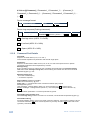
Defining the VP-28 Presentation Switcher
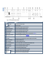
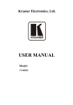
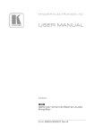
Figure 1 defines the front panel of the VP-28.
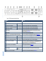
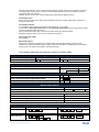
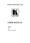
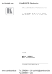
Figure 2 defines the rear panel of the VP-28.
VP-28 - Overview
7
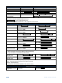
8
Figure 1: VP-28 Presentation Switcher Front Panel
#
1
2
Feature
IR
Function
LED Indicator
Sensor
Lights yellow when receiving IR signals
Receives the IR signal
VP-28 – Overview
3
POWER Switch
Illuminated switch for turning on the power to the device
4
DVI Input Selection Buttons
Press one of the three buttons to select the DVI input
5
HDMI Selection Buttons
Press one of the three buttons to select the HDMI input
6
DP Selection Buttons
Press one of the two buttons to select the DP input
7
HDMI+DP Button
Press to combine/separate the HDMI and DP inputs into a single group (see Section 6.1)
8
MASTER AUDIO SEL Button
Press to select the Master audio channel (see Section 6.2)
9
TALK OVER Button
Press to select the MIC input as the primary audio feed and to lower the background Master audio level (toggle)
10
LOCK Button
Press and hold to lock the front panel buttons. Press and hold again to unlock the buttons
11
MASTER VOLUME Knob
Turn to adjust the master audio level
12
MIC VOLUME Knob
Turn to adjust the microphone audio level
13
MIC IN 6.5mm Microphone Jack
Connect a microphone. Note: Only one microphone can be connected at a time
14
PC Selection Buttons
Press one of the three buttons to select the PC graphics input
15
CV Selection Buttons
Press one of the three buttons to select the CV input
16
MUTE Button
Press to mute/unmute the Master audio output
17
MIX Button
18
MIC SELECT
Button
Press to mix the microphone and Master audio output (toggle)
COND
Depress the button to select a condenser type microphone
DYN
Release the button to select a dynamic type microphone
VP-28 – Overview
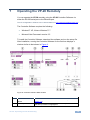
Figure 2: VP-28 Presentation Switcher Rear Panel
#
Feature
Function
19
MIC IN XLR Connector
Connect a microphone. Note: Only one microphone can be connected at a time
20
CV AUDIO 3.5mm Mini Jack Connectors
IN 1 ~ IN 3, OUT
Connect to the audio channel of the CV sources and acceptor
21
CV VIDEO RCA Connectors
IN 1 ~ IN 3, OUT
Connect to the video channel of the CV sources and acceptor
22
HDMI AUDIO 3.5mm Mini Jack Connectors
IN 1 ~ IN 3, OUT
Connect to the audio channel of the HDMI sources and acceptor
23
HDMI VIDEO Connectors
IN 1 ~ IN 3, OUT
24
RESET Button
Press and hold while turning on the power to the device to reset to factory
default settings (see Section 6.4)
25
PROG Button
For the use of Kramer service personnel only
26
MASTER OUT 5-pin Terminal Block Balanced Audio Output
27
DP AUDIO 3.5mm Mini Jack Connectors
IN 1, IN 2, OUT
Connect to the audio channel of the DP sources and acceptor
28
PC AUDIO 3.5mm Mini Jack Connectors
IN 1 ~ IN 3, OUT
Connect to the audio channel of the PC graphics sources and acceptor
29
DVI AUDIO 3.5mm Mini Jack Connectors
IN 1 ~ IN 3, OUT
Connect to the audio channel of the DVI sources and acceptor
30
PC/DVI VIDEO DVI Connectors
IN 1 ~ IN 3, OUT
Connect to the PC graphics (using adapters) or DVI video channel of the video
sources and acceptor. (We recommend the Kramer ADC-DM/DF+GF (one is
supplied with the device) or the C-MDMA/MGMA cable.)
31
RS-232 Serial Port 3-pin Terminal Block
Connect to a serial controller (see Section 5.1)
32
AC Power Mains Socket and Fuse Holder
Connect to the mains power supply
33
DP Connectors
34
ETHERNET LAN RJ-45 Connector
DP IN 1, DP IN 2,
DP OUT
Connect to the video channel of the HDMI sources and acceptor
Connect to the balanced, stereo master audio acceptor (see Section 5.3)
Connect to the video channel of the DisplayPort sources and acceptor
Connect via a LAN to an Ethernet controller (see Section 5.1)
9
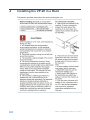
4
Installing the VP-28 in a Rack
This section provides instructions for rack mounting the unit.
10
VP-28 - Installing the VP-28 in a Rack
5
Connecting the VP-28
i
Always switch off the power to any device before connecting it to your
VP-28. After connecting your VP-28, connect its power and then switch
on the power to the other devices.
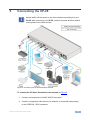
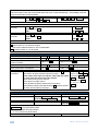
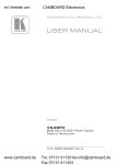
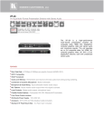
Figure 3: Connecting the VP-28 Presentation Switcher
To connect the VP-28 as illustrated in the example in Figure 3:
1. Connect a microphone to the MIC IN XLR connector.
2. Connect a composite video source (for example, a composite video player)
to the VIDEO IN 1 RCA connector.
VP-28 - Connecting the VP-28
11
3. Connect the composite VIDEO OUT RCA connector to a composite video
acceptor (for example, a projector).
4. Connect an HDMI source (for example, a DVD player) to the HDMI IN 1
HDMI connector.
5. Connect the HDMI OUT connector to an HDMI acceptor (for example, an
LCD TV).
6. Connect a DisplayPort video source (for example, a laptop) to the DP IN 1
DP connector.
7. Connect the DP OUT connector to a DisplayPort video acceptor (for
example, a projector).
8. Connect the DVI AUDIO OUT 3.5mm mini jack connector to an unbalanced,
stereo audio acceptor (for example, a power amplifier).
9. Connect a DVI source (for example, a computer) to the DVI IN 1 connector.
Note: Using the Kramer ADC-DM/DF+GF combined cable increases the
input options available to you.
10. Optional—Connect a PC via Ethernet over a LAN to the Ethernet RJ-45
connector to control the VP-28.
5.1
Connecting a Serial Controller to the VP-28
You can connect to the VP-28 via an RS-232 connection using, for example, a
PC.
To connect to the VP-28 via RS-232:
•
Connect the 3-pin terminal block on the rear panel port of the VP-28 (pin G
to pin 5, pin Rx to pin 3, pin Tx to pin 2) to the RS 232 9-pin D-sub port on
your PC
12
VP-28 - Connecting the VP-28
5.2
Connecting to the VP-28 via Ethernet
You can connect the VP-28 via Ethernet via either of the following methods:
•
•
A crossover cable (see Section 5.2.1) for direct connection to the PC
A straight through cable (see Section 5.2.2) for connection via a network hub
or network router
After connecting the Ethernet port, you have to install and configure your Ethernet Port. For
detailed instructions, see the Ethernet Configuration Guide (Lantronix) in the technical support
section on our Web site http://www.kramerelectronics.com.
5.2.1
Connecting the Ethernet Port directly to a PC
You can connect the Ethernet port on the VP-28 to the Ethernet port on your PC
via a crossover cable with RJ-45 connectors. This type of connection is
recommended for identification of the factory default IP Address of the VP-28
during the initial configuration.
To configure your PC after connecting the Ethernet port:
1. Right-click the My Network Places icon on your desktop.
2. Select Properties.
3. Right-click Local Area Connection Properties.
4. Select Properties.
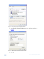
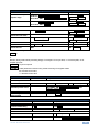
The Local Area Connection Properties window appears.
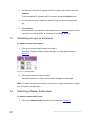
5. Select the Internet Protocol (TCP/IP) and click the Properties Button.
VP-28 - Connecting the VP-28
13
Figure 4: Local Area Connection Properties Window
6. Select Use the following IP Address and enter the details as shown in
Figure 5.
Figure 5: Internet Protocol (TCP/IP) Properties Window
7. Click OK.
14
VP-28 - Connecting the VP-28
5.2.2
Connecting to the Ethernet Port via a Network Switch/Hub
To connect to the Ethernet port on the VP-28 via a network switch/hub:
•
Connect the PC to the Ethernet network switch/hub using a straight through
cable
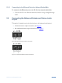
5.3
Connecting the Balanced/Unbalanced Stereo Audio
Output
This section illustrates how to wire the devices to the balanced audio output:
•
A balanced stereo output connection, see Figure 6
•
An unbalanced stereo output connection, see Figure 7
Figure 6: Balanced Stereo Audio Connection
Figure 7: Unbalanced Stereo Audio Connection
VP-28 - Connecting the VP-28
15
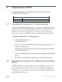
6
Operating the VP-28
The input/output button color indicates the current state of the channel as
described in the following table.
Button Color
Red
Purple
Green
6.1
State
Selected group input
Selected group input + active Master audio input
Selected Master audio input
Operating the Combined 5 x 1 Switching Group
By default, the VP-28 operates as a four 3 x 1 and one 2 x 1 switcher whereby the
video and audio for each group is switched to the output of the same group. The
VP-28 can also combine the HDMI and DP inputs into a single 5-input group
where any one of the five HDMI/DP inputs can be switched to the HDMI output.
To operate the combined 5 x 1 switching group:
1. Press the HDMI+DP button.
The button lights red.
2. Press one of the three HDMI or two DP input buttons to select an input to
switch to the HDMI output.
The selected input button lights red and the input is switched to the HDMI
video and audio outputs.
3. Press the HDMI+DP button to return the switching to separate HDMI and DP
groups.
The button no longer lights and switching is returned to separate groups.
6.2
Operating the Combined 14 x 1 Master Audio Switching
Group
The VP-28 operates in the audio-follow-video mode whereby the audio for each
group is switched to the output of the same group. The VP-28 also operates in a
combined 14 x 1 mode whereby any one of 14 audio inputs can be switched to the
master balanced audio output.
16
VP-28 - Operating the VP-28
To operate the combined 14 x 1 Master audio switching group:
1. Press the Master Audio Sel button.
The button lights red.
2. Press one of the 14 input select buttons (three DVI, three PC, three HDMI,
three CV and two DP) to switch the audio to the Master Out connector.
The selected button lights green and the input is switched to the Master
Audio output.
Note: If this is the same input as is selected for the audio group selection, the button
lights purple.
3. Press the Master Audio Sel button to exit the Master audio selection and
return to the group selection.
The button no longer lights but the last Master audio selection remains
active.
6.3
Locking the Front Panel
Lock your VP-28 to prevent changing the settings accidentally or the front panel
buttons being tampered with.
To lock the front panel of the VP-28:
•
Press and hold the LOCK button.
The LOCK button lights and the front panel buttons are locked. Pressing any
button has no effect but the LOCK button flashes briefly. The VP-28 can be
operated via the remote IR controller, RS-232 or Ethernet
To unlock the front panel of the VP-28:
•
Press and hold the LOCK button.
The front panel buttons are unlocked and the LOCK button no longer lights
VP-28 - Operating the VP-28
17
6.4
Resetting the VP-28 to the Factory Default
To reset the VP-28 to factory defaults:
1. Switch off the VP-28.
2. Press and hold the RESET button on the rear panel.
3. Switch on the VP-28.
4. Wait a few seconds and release the button.
The parameters and configuration are reset to their factory defaults (see
Section 9).
18
VP-28 - Operating the VP-28
7
Operating the VP-28 Remotely
You can operate the VP-28 remotely using the VP-28 Controller Software via
either the RS-232 serial port or the Ethernet port.
The VP-28 Application Software can be downloaded from http://www.kramerelectronics.com.
The Controller Software requires the following:
•
Windows™ XP, Vista or Windows™ 7
•
Microsoft .Net Framework version 3.5
To install the Controller Software, download the software and run the setup file.
After installation, running the Controller Software for the first time displays a
window similar to that shown in Figure 8.
Figure 8: Controller Software Main Window
#
1
2
Feature
Connect/Disconnect
Button
Select Input Buttons
Function
Click to connect to or disconnect from the device (see
Section 7.2)
Click one of the 14 input buttons to select an input. The
selected input button is highlighted
VP-28 - Operating the VP-28 Remotely
19
#
Feature
Function
3
Combine Button
4
Audio Master Level
Adjustment
Status Indicator
Click to combine the three HDMI and two DisplayPort inputs
into five inputs
Use either the slider or click on the up/down arrows to adjust
the master audio level
Indicates whether or not the application is connected to the
device
Use either the slider or click on the up/down arrows to adjust
the microphone audio level
Click to mute/unmute the output volume
Press to select the MIC input as the primary audio feed and to
lower the background Master audio level (toggle)
Click to select/deselect the talkover audio signal to output
Click to select one of the audio inputs
5
6
7
8
9
10
Audio Mic Level
Adjustment
Mute Check Box
Talkover Check Box
Mix Check Box
Master Audio Dropdown List
Note: When a change is made on the device (for example, a different output is
selected), the change is reflected almost immediately in the main window of the
Controller Software, and visa versa.
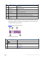
Figure 9 shows a typical input button.
Figure 9: Typical Input Button
20
#
1
2
Feature
1
Description
Input or output number
User-selectable icon selected to be displayed on the button
3
4
Input HDMI 1 Label
Background Color
5
Audio Input
User-selectable button label
Indicates the status of the input/output:
Purple—active
White—inactive
The symbol indicates that this is the selected audio input (see
Section 7.3)
VP-28 - Operating the VP-28 Remotely
7.1
The Controller Software Menu Bar
The following table describes the Controller Software menu bar options.
Menu Bar
Options
Sub Menu
Description
File
Open
Save
Exit
Connect/Disconnect
Firmware Upgrade
Open an existing project
Save the current project
Exit the Controller software
Connect or disconnect to the device
Upgrade the device firmware using a new firmware
file
Display the device details, such as, model, unit name,
IP settings, and so on
Displays the Controller Software and Kramer
company details
Device
Device Details
ABOUT
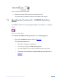
7.2
NA
Connecting to the Device
To connect to the device:
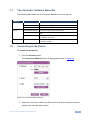
1. Click the Connect button.
The Connection Method window is displayed as shown in Figure 10.
Figure 10: Connection Method Window
2. Select the connection method (via Ethernet over a LAN or serial connection)
selecting the relevant option button.
VP-28 - Operating the VP-28 Remotely
21
3. For Ethernet, enter the IP address and Port number of the device and click
Connect.
To set the default IP address and Port number, press the Default button.
4. For a serial connection, select the required Com port from the drop-down
list.
5. Click Connect.
If the connection is successful, the window shown in Figure 8 appears. If the
connection is not successful, a Timeout error message appears.
7.3
Switching an Input to an Output
To switch an input to an output:
1. Click on the required input button to activate it.
The input is selected and the button changes to solid purple as shown in
Figure 11.
Figure 11: Input Selection
2. Click on the required output to select.
The switch selection is made and the button changes to solid purple.
Note: To switch an input to an output, you can click on either an input or an output
first, the order is not important.
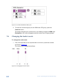
7.4
Selecting a Master Audio Input
To select a master audio input:
1. Click on the Master Audio drop-down list as shown in Figure 12.
22
VP-28 - Operating the VP-28 Remotely
Figure 12: Master Audio Input Selection
2. Select the required audio input from the drop-down list.
The audio input is selected to switch to the master audio output.
7.5
Operating the Combined 5 x 1 HDMI/DP Switching
Group
The HDMI and DP inputs can be grouped together into a single 5 x 1 switching
group.
Figure 13: Combine Button
To combine the HDMI and DP inputs into a 5 x 1 switching group:
1. Click on the Combine button as shown in Figure 13.
The following changes occur:
The button changes to a locked icon
The heading changes to HDMI & DisplayPort:
An outline appears around both the HDMI and DP input buttons
The inputs are combined into a single switching group as shown in
Figure 14.
VP-28 - Operating the VP-28 Remotely
23
Figure 14: Combined HDMI and DP Inputs
2. To break the combined group into an HDMI and a DP group, press the
Combine button.
The button changes to an unlocked icon, the heading changes to HDMI: and
DisplayPort:, the outline disappears and the inputs are no longer grouped.
7.6
Changing the Audio Levels
To change the audio levels:
•
Click, hold and slide on the required slider or click the up and down arrows
as shown in Figure 15.
The volume level changes accordingly.
Figure 15: Changing the Audio Levels
24
VP-28 - Operating the VP-28 Remotely
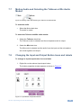
7.7
Muting Audio and Selecting the Talkover or Mix Audio
Modes
Figure 16: Muting Audio and Selecting the Talkover and Mix Modes
To mute the audio:
•
Select the Mute check box.
The audio is muted.
To select the Talkover and Mix audio modes:
1. Select the Talkover check box.
The Talkover mode is selected and the microphone audio is output.
2. Select the Mix check box.
The Mix mode is selected and the audio from the input and the microphone
are mixed together and output.
7.8
Changing the Input and Output Button Icons and Labels
To change an input/output button icon and label:
1. Right-click on the relevant input/output button.
The button properties window appears as shown in Figure 17.
Figure 17: Input Button Properties Window
VP-28 - Operating the VP-28 Remotely
25
2. In the Label text field, enter the required button label.
3. Either:
Select the required icon from the list (you can save custom icons)
OR
Click Select icon from file and browse to the icon directory
4. Click OK.
The button characteristics are changed.
7.9
Upgrading the Firmware
To upgrade the firmware:
1. Download the latest firmware file from http:www.kramerelectronics.com.
2. Click Device > Firmware Upgrade.
3. Browse to the firmware file that you downloaded.
4. Click Open.
The device firmware is loaded.
Note: Do not interrupt the uploading process or the device may be
damaged.
5. When the process is complete power cycle the device.
7.10
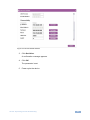
Setting the IP Network Parameters
To set the IP network parameters:
1. Click Device > Device Details.
2. Under Connectivity, edit the required parameter as shown in Figure 18.
26
VP-28 - Operating the VP-28 Remotely
Figure 18: Device Details Window
3. Click Set Value.
A confirmation message appears.
4. Click OK.
The parameter is set.
5. Power cycle the device.
VP-28 - Operating the VP-28 Remotely
27
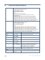
8
28
Technical Specifications
INPUTS:
Video:
3 Composite video on RCA connectors
3 HDMI on HDMI connectors
2 DP on DisplayPort connectors
3 PC/DVI on DVI connectors
Audio:
1 Microphone on an XLR connector
1 Microphone on a 6.3mm phone jack connector (3mV / 10kΩ
condenser/dynamic)
3 Unbalanced stereo audio on 3.5mm mini jack connectors (for CV)
3 Unbalanced stereo audio on 3.5 mini jack connectors (for HDMI)
2 Unbalanced stereo audio on 3.5mm mini jack connectors (for DP)
3 Unbalanced stereo audio on 3.5mm mini jack connectors (for PC audio)
3 Unbalanced stereo audio on 3.5mm mini jack connectors (for DVI)
OUTPUTS:
Video:
1 Composite video on an RCA connector
1 HDMI on an HDMI connector
1 DP on a DisplayPort connector
1 PC/DVI on a DVI connector
Audio:
1 Unbalanced stereo audio on a 3.5mm mini jack connector (for CV)
1 Unbalanced stereo audio on a 3.5 mini jack connector (for HDMI)
1 Unbalanced stereo audio on a 3.5mm mini jack connector (for DP)
1 Unbalanced stereo audio on a 3.5mm mini jack connector (for PC audio)
1 Unbalanced stereo audio on a 3.5mm mini jack connector (for DVI)
1 Master balanced stereo audio on a 5-pin terminal block
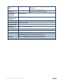
VIDEO
AUDIO
MAX. OUTPUT
LEVEL:
CV: 1.7Vpp
XGA: 2.3Vpp
Master: 17Vpp from Mic, 12.4Vpp from Line in
Local Out: 8.8Vpp from line inputs
BANDWIDTH
(-3dB):
CV: 680MHz
XGA: 290MHz
(–4dB 400MHz)
>25kHz
DIFF. GAIN:
CV: 2.5%
XGA: 0.1%
DIFF. PHASE:
CV: 0.4 Deg.
XGA: 0.1 Deg.
K-FACTOR:
CV: <0.05%
XGA: <0.05%
S/N RATIO:
CV: 74dB
XGA: 71dB @5MHz
Master: 81dB from Mic (@20mVpp input, 17Vpp
output diff, “A” weighting, XLR microphone)
90 to 95dB from Line in (“A” weighting)
Local Outputs: 110dB (“A” weighting)
CROSSTALK
@1kHz (all hostile):
CV: –54dB
XGA: –56dB (5MHz)
Master: –70dB
Local Outputs: –80dB from Line in
CONTROLS (Level
Range):
MASTER: <–12 to 70dB from Mic, –79 to +15dB from Line in
COUPLING:
CV: DC
XGA: DC
AC
VP-28 - Technical Specifications
AUDIO THD +
NOISE:
Master: 0.4% from Mic, 0.02% from Line in (“A”
weighting)
Local out: 0.04% from Line in
AUDIO 2nd
HARMONIC:
Master: 0.0.3% from Mic, 0.01% from Line in
Local out: 0.02% from Local output
COMPLIANCE
WITH HDCP
STANDARD:
Supports HDCP
MAXIMUM
BANDWIDTH DP
TO HDMI:
One or two lane (1.65Gbps per lane)
INDICATOR LEDs:
IR
POWER SOURCE:
90–264V AC, 23VA
OPERATING
TEMPERATURE:
0° to +55°C (32° to 131°F)
STORAGE
TEMPERATURE:
-45° to +72°C (-49° to 162°F)
HUMIDITY:
10% to 90%, RHL non-condensing
DIMENSIONS:
19” x 7.35” x 1U (W, D, H) rack mountable
WEIGHT:
1.8kg (3.97lbs) approx.
ACCESSORIES:
Power cord, rack “ears”, Kramer infrared remote control transmitter, Kramer
ADC-DM/DF+GF DVI to DVI and VGA breakout cable
OPTIONS:
Kramer C-MDMA/MGMA DVI/VGA/audio breakout cable
Specifications are subject to change without notice at http://www.kramerelectronics.com
VP-28 - Technical Specifications
29
9
Default Parameters
9.1
Default Communication Parameters
EDID
EDID data is passed between connected outputs and inputs in the DVI, VGA, HDMI or DP groups
RS-232
Protocol 3000 (Default)
Baud Rate
115,200
Data Bits
8
Stop Bits
1
Parity
None
Command Format
ASCII
Example (Output 1 to Input 1)
#AV 1>1<CR>
Ethernet
To reset the IP settings to the factory reset values, power cycle the device while holding in
the Factory Reset button, located on the rear panel of the unit
9.2
IP Address
192.168.1.39
Subnet mask
255.255.255.0
Default gateway
192.168.1.1
TCP Port #
5000
UDP Port #
50000
Maximum UDP Ports
10
Maximum TCP Ports
4
Default Video/Audio Parameters
Item
Switched input in all groups
Master audio gain
Mic audio gain
30
Description
1
0dB
0dB
VP-28 - Default Parameters
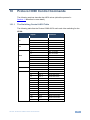
10
Protocol 3000 Control Commands
The following sections describe the ASCII values (which the protocol in
Section 11 describes in more detail).
10.1.1
The Switching Control ASCII Table
The following table lists the Protocol 3000 ASCII audio and video switching for the
VP-28.
Inputs
Group
DVI
VGA
HDMI
CV
DP
Master Audio
Command
#
In 1
In 2
In 3
In 1
In 2
In 3
In 1
In 2
In 3
In 4
In 5
In 1
In 2
In 3
In 1
In 2
#AV 1>1<CR>
#AV 2>1<CR>
#AV 3>1<CR>
#AV 1>2<CR>
#AV 2>2<CR>
#AV 3>2<CR>
#AV 1>3<CR>
#AV 2>3<CR>
#AV 3>3<CR>
#AV 4>3<CR>
#AV 5>3<CR>
#AV 1>4<CR>
#AV 2>4<CR>
#AV 3>4<CR>
#AV 1>5<CR>
#AV 2>5<CR>
In 1
In 2
In 3
In 4
DVI 1
DVI 2
DVI 3
VGA 1
#AUD 1>6<CR>
#AUD 2>6<CR>
#AUD 3>6<CR>
#AUD 4>6<CR>
In 5
In 6
VGA 2
VGA 3
#AUD 5>6<CR>
#AUD 6>6<CR>
In 7
In 8
In 9
In 10
In 11
In 12
In 13
In 14
HDMI 1
HDMI 2
HDMI 3
CV 1
CV 2
CV 3
DP 1
DP 2
#AUD 7>6<CR>
#AUD 8>6<CR>
#AUD 9>6<CR>
#AUD 10>6<CR>
#AUD 11>6<CR>
#AUD 12>6<CR>
#AUD 13>6<CR>
#AUD 14>6<CR>
VP-28 - Protocol 3000 Control Commands
31
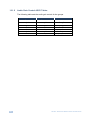
10.1.2
Audio Gain Control ASCII Tables
The following table sets the audio gain control for the groups.
…..
…..
…..
Master Output
MIC Output
Gain
# AUD-LVL 2,6,–80<CR> # AUD-LVL 2,7,–80<CR> –80dB (mute)
…..
0dB (1:1)
# AUD-LVL 2,6,15<CR>
# AUD-LVL 2,7,15<CR>
15dB (max)
…..
# AUD-LVL 2,7,0<CR>
…..
# AUD-LVL 2,6,0<CR>
…..
32
…..
…..
# AUD-LVL 2,6,–50<CR> # AUD-LVL 2,7,–50<CR> –50dB (mute)
VP-28 - Protocol 3000 Control Commands
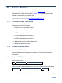
11
Kramer Protocol
By default, the VP-28 is set to Protocol 3000 (see Section 11.2) but is also
compatible with Kramer’s Protocol 2000. Section 13.2 describes how to switch
between Protocol 3000 and Protocol 2000.
You can download our user friendly “Software for Calculating Hex Codes for Protocol 2000”
from the technical support section at http://www.kramerelectronics.com.
11.1
Protocol Output Definitions
The protocol output definitions are:
11.2
•
DVI video group defined as output 1
•
VGA video group defined as output 2
•
HDMI video group defined as output 3
•
CV video group defined as output 4
•
DP video group defined as output 5
•
Master audio selector defined as output 6
•
MIC audio defined as output 7
Kramer Protocol 3000
The Protocol 3000 RS-232 communication protocol lets you control the machine
from any standard terminal software (for example, Windows® HyperTerminal
Application).
11.2.1
Protocol 3000 Syntax
Host message format:
Start Address (optional)
#
Destination_id@
Body
message
Delimiter
CR
Simple command (commands string with only one command without addressing):
start
#
body
Command SP Parameter_1,Parameter_2,…
delimiter
CR
Commands string (formal syntax with commands concatenation and addressing):
VP-28 - Kramer Protocol
33
# Address@ Command_1 Parameter1_1,Parameter1_2,… |Command_2
Parameter2_1,Parameter2_2,… |Command_3 Parameter3_1,Parameter3_2,…
|…CR
Device message format:
Start Address (optional)
~
Sender_id@
Body
message
Delimiter
CR LF
Device long response (Echoing command):
Start
Address (optional)
~
Sender_id@
Body
command SP [param1 ,param2
…] result
Delimiter
CR LF
CR = Carriage return (ASCII 13 = 0x0D)
LF = Line feed (ASCII 10 = 0x0A)
SP = Space (ASCII 32 = 0x20)
11.2.2
Command Part Details
Command:
Sequence of ASCII letters ('A'-'Z', 'a'-'z' and '-').
Command will separate from parameters with at least single space.
Parameters:
Sequence of Alfa-Numeric ASCII chars ('0'-'9','A'-'Z','a'-'z' and some special chars for specific
commands), parameters will be separated by commas.
Message string:
Every command must to be entered as part of message string that begin with message starting
char and end with message closing char, note that string can contain more then one command
separated by pipe ("|") char.
Message starting char:
'#' for host command\query.
'~' for machine response.
Device address (Optional, for KNET):
KNET Device ID follow by '@' char.
Query sign = '?', will follow after some commands to define query request.
Message closing char =
Host messages - Carriage Return (ASCII 13), will be referred to by CR in this document.
Machine messages - Carriage Return (ASCII 13) + Line-Feed (ASCII 10), will be referred to by
CRLF.
Spaces between parameters or command parts will be ignored.
Commands chain separator char:
When message string contains more than one command, commands will be separated by pipe ("|").
Commands entering:
If terminal software used to connect over serial \ ethernet \ USB port, that possible to directly enter all
commands characters (CR will be entered by Enter key, that key send also LF, but this char will be
ignored by commands parser).
34
VP-28 - Kramer Protocol
Sending commands from some controllers (like Crestron) require coding some characters in special
form (like \X##). Anyway, there is a way to enter all ASCII characters, so it is possible to send all
commands also from controller.
(Similar way can use for URL \ Telnet support that maybe will be added in future).
Commands forms:
Some commands have short name syntax beside the full name to allow faster typing, response is
always in long syntax.
Commands chaining:
It is possible to enter multiple commands in same string by '|' char (pipe).
In this case the message starting char and the message closing char will be entered just one time,
in the string beginning and at the end.
All the commands in string will not execute until the closing char will be entered.
Separate response will be sent for every command in the chain.
Input string max length:
64 characters.
Backward support:
Design note: transparent supporting for protocol 2000 will be implemented by switch protocol
command from protocol 3000 to protocol 2000, in protocol 2000 there is already such a command to
switch protocol to ASCII protocol (#56 : H38 H80 H83 H81).
The following table lists the instruction codes for Protocol 3000.
Help commands
Command
Protocol Handshaking
Syntax
#CR
Response
~OKCRLF
Device initiated messages
Command
Start message
Syntax
Kramer Electronics LTD. , Device Model
Version Software Version
Switcher actions
Audio-video channel has switched (AFV mode)
AV IN>OUT
Video channel has switched (Breakaway mode)
VID IN>OUT
Audio channel has switched (Breakaway mode)
AUD IN>OUT
Result codes (errors)
Syntax
COMMAND PARAMETERS OK
No error. Command running succeeded
Protocol Errors
Syntax Error
ERR001
Command not available for this device
ERR002
Parameter is out of range
ERR003
Unauthorized access (running command without the match login).
ERR004
Basic routing commands
Command
Syntax
Switch audio & video AV IN>OUT, IN>OUT, …
Response
AV IN>OUT, IN>OUT,…RESULT
Switch video only
VID IN>OUT, IN>OUT, …RESULT
VID IN>OUT, IN>OUT, …
Short form: V IN>OUT, IN>OUT, …
VP-28 - Kramer Protocol
35
Note:
When AFV mode is active, this command will switch also audio. If audio is breakaway – device display mode will
change to show audio connections status.
Switch audio only
AUD IN>OUT, IN>OUT, …
Short form: A IN>OUT, IN>OUT, …
AUD IN>OUT, IN>OUT, …RESULT
Note: When AFV mode is active, this command will switch also video.
Read video
connection
Read audio
connection
VID? OUT
Short form: V? OUT
VID? *
VID IN>OUT
AUD? OUT
Short form: A? OUT
AUD? *
AUD IN>OUT
VID IN>1, IN>2, …
AUD IN>1, IN>2, …
Parameters Description:
IN = Input number or '0' to disconnect output.
'>' = Connection character between in and out parameters.
OUT = Output number or '*' for all outputs.
Examples:
Switch Video and Audio input 3 to output 7 #AV 3>7CR
~AV 3>7 OKCRLF
Switch Video input 2 to output 4
#V 2>4CR
~VID 2>4 OKCRLF
Switch Video input 4 to output 2 in
machine number 6
#6@VID 4>2CR
~6@VID 4>2 OKCRLF
Disconnect Video and Audio Output 4
#AV 0>4CR
~AV 0>4 OKCRLF
Switch Video Input 3 to All Outputs
#V 3>*CR
~VID 3>* OKCRLF
Chaining Multiple
commands*
#AV 1>* | V 3>4, 2>2, 82>1, 0>2 |V 82>3| A 0>1 | V? * CR
First switch all Audio and video outputs from input 1,
Then switch video input 3 to output 4, video input 2 to output
2, video input and disconnect video output 2.
Then switch audio input 3 to output 2,
Then disconnect audio output 1.
Then get status of all links (assume this is 4x4 matrix).
Commands processing start after entering CR, response will sent
for each command after processing it.
~AV 1>* OKCRLF
~VID 1>2, 3>4 OKCRLF
~VID 82>3 ERR###
CRLF
~AUD 0>1 OKCRLF
~V 1>1, 0>2, 1>3, 3>4
CRLF
Operation commands
Command
Lock front panel
Syntax
LOCK-FP LOCK-MODE
Short form: LCK LOCK-MODE
Response
LOCK-FP LOCK-MODE RESULT
Get front panel locking state
LOCK-FP?
LOCK-FP LOCK-MODE
Parameters Description:
LOCK-MODE = Front panel locking state:
"0" or "off" to unlock front panel buttons.
"1" or "on" to lock front panel buttons.
Restart device
RESET
36
RESET OK
VP-28 - Kramer Protocol
Audio parameters commands
Command
Set audio level in specific
amplifier stage.
Syntax
AUD-LVL STAGE, CHANNEL, VOLUME
Short form: ADL STAGE, CHANNEL, VOLUME
Response
AUD-LVL STAGE,
CHANNEL, VOLUME
RESULT
Read audio volume level
AUD-LVL? STAGE, CHANNEL
Short form: ADL? STAGE
AUD-LVL STAGE,
CHANNEL, VOLUME
Mute audio
MUTE MUTE-MODE
MUTE MUTE-MODE
RESULT
Read audio mute state
MUTE?
MUTE MUTE-MODE
Set talk over
TLK TALKOVER_MODE
TLK TALKOVER_MODE
RESULT
Read talk over
TLK?
TLK TALKOVER_MODE
Set audio mix
MIX MIX-MODE
MIX MIX-MODE RESULT
Read audio mix
MIX?
MIX MIX-MODE
Parameters Description:
STAGE =
"In","Out"
or
Numeric value (present audio processing stage). For example: "0" for Input level, "1" for Pre-Amplifier, "2" for
Amplifier (Out) etc.
CHANNEL = Input or Output #
VOLUME = Audio parameter in Kramer units, precede minus sign for negative values.
++ increase current value,
-- decrease current value.
Machine info commands
Command
Syntax
Response
* Time settings commands require admin authorization
INFO-IO?
Read in\outs count
INFO-IO: IN INPUTS_COUNT, OUT OUTPUTS_COUNT
Read max presets count
INFO-PRST?
INFO-PRST: VID PRESET_VIDEO_COUNT, AUD
PRESET_AUDIO_COUNT
Reset configuration to
factory default
FACTORY
FACTORY RESULT
Identification commands
Command
Syntax
Response
Protocol Handshaking
#CR
~OK CRLF
Read device model
MODEL?
MODEL MACHINE_MODEL
Read device serial number
SN?
SN SERIAL_NUMBER
Read device firmware
VERSION?
VERSION MAJOR .MINOR .BUILD .REVISION
VP-28 - Kramer Protocol
37
Identification commands
Command
version
Syntax
Response
Set machine name
NAME MACHINE_NAME
NAME MACHINE_NAME RESULT
Read machine name
NAME?
NAME MACHINE_NAME
Reset machine name to
factory default*
NAME-RST
NAME-RST MACHINE_FACTORY_NAME
RESULT
*Note: machine name not equal to model name. This name relevance for site viewer identification of specific
machine or for network using (with DNS feature on).
MACHINE_NAME = Up to 14 Alfa-Numeric chars.
* Machine factory name = Model name + last 4 digits from serial number.
Set IP address
Read IP address
Ethernet Commands
NET-IP IP_ADDRESS
NET-IP IP_ADDRESS RESULT
Short form: NTIP
NET-IP?
NET-IP IP_ADDRESS
Short form: NTIP?
Read MAC address
NET-MAC?
Short form: NTMC
NET-MAC MAC_ADDRESS
Set subnet mask
NET-MASK SUBNET_MASK
Short form: NTMSK
NET-MASK SUBNET_MASK RESULT
Read subnet mask
NET-MASK?
Short form: NTMSK?
NET-MASK SUBNET_MASK
Set gateway address
NET-GATE GATEWAY_ADDRESS
Short form: NTGT
NET-GATE GATEWAY_ADDRESS RESULT
Read subnet mask
NET-GATE?
Short form: NTGT?
NET-GATE GATEWAY_ADDRESS
Set DHCP mode
NET-DHCP DHCP_MODE
Short form: NTDH
NET-DHCP DHCP_MODE RESULT
Read subnet mask
NET-DHCP?
Short form: NTDH?
NET-DHCP DHCP_MODE
DHCP_MODE =
‘0’ – Don't use DHCP (Use IP set by factory or IP set command).
‘1’ – Try to use DHCP, if unavailable use IP as above.
Change protocol
Ethernet port
ETH-PORT PROTOCOL , PORT
Short form: ETHP
ETH-PORT PROTOCOL ,PORT RESULT
Read protocol
Ethernet port
ETH-PORT? PROTOCOL
Short form: ETHP?
ETH-PORT PROTOCOL , PORT
PROTOCOL = TCP/UDP (transport layer protocol)
PORT = Ethernet port that accepts Protocol 3000 commands
1-65535 = User defined port
0 - Reset port to factory default (50000 for UDP, 5000 for TCP)
Reset to factory default
configuration
38
FACTORY
Factory Commands
FACTORY RESULT
VP-28 - Kramer Protocol
For the latest information on our products and a list of Kramer distributors,
visit our Web site where updates to this user manual may be found.
We welcome your questions, comments, and feedback.
Web site: www.kramerelectronics.com
E-mail: [email protected]
!
SAFETY WARNING
Disconnect the unit from the power
supply before opening and servicing
P/N: 2900- 300080
Rev: 2