1
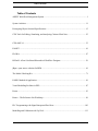
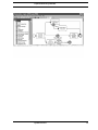
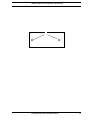
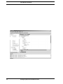
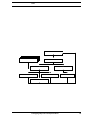
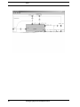
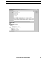
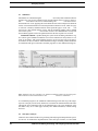
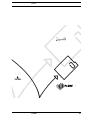
June 2003
Tool Demonstrations
Organized by Eric Verbeek
24th International Conference on Application and
Theory of Petri Nets
International Conference on Business Process
Management
Eindhoven, The Netherlands, June 23–27, 2003
Tool Demonstrations
Table of Contents
Table of Contents
ADEPT Workflow Management System......................................................................................... 1
System Architect ............................................................................................................................ 11
Prototyping Object Oriented Specifications................................................................................... 15
CPN Tools for Editing, Simulating, and Analysing Coloured Petri Nets ...................................... 25
CPN-AMI 2.6 ................................................................................................................................. 35
FileNET.......................................................................................................................................... 41
FLOWer ......................................................................................................................................... 47
HiWorD: A Petri Net-Based Hierarchical Workflow Designer..................................................... 59
jBpm : open source solution for BPM............................................................................................ 61
The Model-Checking Kit ............................................................................................................... 71
PARIS: Method & Application ...................................................................................................... 81
Visual Modelling Facilities in PEP ................................................................................................ 87
Protos.............................................................................................................................................. 93
Renew – The Reference Net Workshop......................................................................................... 99
PLC Programming with Signal Interpreted Petri Nets................................................................. 103
Modelling and Validation with VipTool...................................................................................... 113
Table of Contents
Introduction
ADEPT Workflow Management System
1
Features of the ADEPT WfMS
2
ADEPT Workflow Management System
ADEPT Components, Architecture, and Interfaces
ADEPT Workflow Management System
3
ADEPT Components, Architecture, and Interfaces
4
ADEPT Workflow Management System
ADEPT Components, Architecture, and Interfaces
ADEPT Workflow Management System
5
ADEPT Components, Architecture, and Interfaces
6
ADEPT Workflow Management System
ADEPT Components, Architecture, and Interfaces
ADEPT Workflow Management System
7
Practical Use and Lessons Learned
8
ADEPT Workflow Management System
Practical Use and Lessons Learned
ADEPT Workflow Management System
9
Summary
10
ADEPT Workflow Management System
Popkin Software & Systems BV
System Architect
11
Popkin Software & Systems BV
12
System Architect
Popkin Software & Systems BV
System Architect
13
Popkin Software & Systems BV
14
System Architect
Introduction
Prototyping Object Oriented Specifications
15
CO-OPN Specification Language
16
Prototyping Object Oriented Specifications
ADEPT Components, Architecture, and Interfaces
Prototyping Object Oriented Specifications
17
CoopnBuilder Framework
18
Prototyping Object Oriented Specifications
Tools
Prototyping Object Oriented Specifications
19
Tools
20
Prototyping Object Oriented Specifications
Code Generation
Prototyping Object Oriented Specifications
21
Code Generation
22
Prototyping Object Oriented Specifications
Related Work
Prototyping Object Oriented Specifications
23
References
24
Prototyping Object Oriented Specifications
Introduction
CPN Tools for Editing, Simulating, and Analysing
Coloured Petri Nets
Anne Vinter Ratzer, Lisa Wells, Henry Michael Lassen, Mads Laursen, Jacob Frank
Qvortrup, Martin Stig Stissing, Michael Westergaard, Søren Christensen, Kurt Jensen
Department of Computer Science, University of Aarhus
IT-parken, Aabogade 34, DK-8200, Århus N, Denmark
Abstract. CPN Tools is a tool for editing, simulating and analysing Coloured Petri
Nets. The GUI is based on advanced interaction techniques, such as toolglasses,
marking menus, and bi-manual interaction. Feedback facilities provide contextual error messages and indicate dependency relationships between net elements. The tool
features incremental syntax checking and code generation which take place while a
net is being constructed. A fast simulator efficiently handles both untimed and timed
nets. Full and partial state spaces can be generated and analysed, and a standard state
space report contains information such as boundedness properties and liveness properties. The functionality of the simulation engine and state space facilities are similar
to the corresponding components in Design/CPN, which is a widespread tool for
Coloured Petri Nets.
1 Introduction
CPN Tools is a tool for editing, simulating and analysing untimed and timed, hierarchical
Coloured Petri nets (CPN or CP-nets) [1,2]. CPN Tools is intended to replace Design/CPN
[3], which is a widespread software package for CP-nets. In addition to Design/CPN, CPN
Tools can be compared to other Petri net tools such as ExSpect, GreatSPN, and Renew
which are all described in the Petri Nets Tool Database [4].
Design/CPN was first released in 1989 with support for editing and simulating CPnets. Since then a significant amount of time has been invested in developing efficient
and advanced support both for simulation and for generating and analysing full, partial,
and reduced state spaces. While the analysis components of Design/CPN have steadily
improved since 1989, the graphical user interface has remained virtually unchanged.
CPN Tools is the result of a research project, the CPN2000 project [5], at the University
of Aarhus, sponsored by the Danish National Centre for IT Research (CIT), George Mason
University, Hewlett-Packard, Nokia, and Microsoft. The goal of the CPN2000 project was
to take advantage of the developments in human-computer interaction, and to experiment
with these techniques in connection with a complete redesign of the GUI for Design/CPN.
The resulting CPN Tools combines powerful functionalities with a flexible user interface,
containing improved interaction techniques, as well as different types of graphical feedback
which keep the user informed of the status of syntax checks, simulations, etc. All models
that are created in Design/CPN can be converted and then used in CPN Tools; the reverse,
however, is not true.
This paper is organised as follows. Section 2 introduces the new interaction techniques
and components of the GUI. Section 3 describes how to edit CP-nets in CPN Tools. Finally,
Sect. 4 describes the simulation and state space facilities that are provided in CPN Tools.
2 The CPN Tools Interface
The CPN Tools interface requires a keyboard and at least one pointing device. Actually,
the interface supports and encourages the use of two or more pointing devices. For a righthanded user we recommend using a mouse for the right hand and a trackball for the left
CPN Tools for Editing, Simulating, and Analysing Coloured Petri Nets
25
The CPN Tools Interface
Fig. 1. The CPN Tools interface. The left column is called the index. The top-left and top-right binders
contain sheets with different views of the same page. The bottom binder contains six sheets represented by tabs. The front sheet, containing the page named Top, shows a number of magnetic guidelines for easier alignment of objects. In the bottom-left binder, containing a declaration, a circular
marking menu has been popped up. The small binder on the right-hand side contains two sheets with
tool palettes. The palette in the front (Create) contains tools for creating CP-net objects and guidelines. A toolglass is positioned over the sheet in the top-right binder. This toolglass can be used to
edit colours, line styles and line widths.
hand. The mouse is used for tasks that may require precision, while the trackball is used
for tasks that do not require much precision e.g. moving tools. For simplicity we assume
a right-handed user in our description of interaction techniques. We describe how such a
person would typically use the right or left hand, but it should be noticed that all operations
can be done using either hand.
The interface has no menu bars or pull-down menus, and only few scrollbars and dialog
boxes. Instead, it uses a combination of traditional, recent and novel interaction techniques,
which are described below. Figure 1 shows the GUI for CPN Tools.
Workspace management makes it easy to manage the large number of pages that are
typically found in industrial-sized CP-nets. The workspace occupies the whole screen and
contains window-like objects called
. Binders contain
where each sheet is
equivalent to a window in a traditional environment. A sheet provides a view of either a
page from a CP-net, or declarations, or a set of tools. Each sheet has a tab similar to those
found in tabbed dialogs. Clicking the tab brings that sheet to the front of the binder. A
sheet can be dragged to a different binder or to the background to create a new binder
for it. Binders reduce the number of windows on the screen and the time spent organising
26
CPN Tools for Editing, Simulating, and Analysing Coloured Petri Nets
The CPN Tools Interface
them. Binders also help users organise their work by grouping related sheets together and
reducing the time spent looking for hidden windows.
CPN Tools supports multiple views, allowing several sheets to contain different views
of the same page. For example, one sheet can provide a close-up view of a small part of a
page while another sheet can provide a view of the same page at a much smaller scale (see
figure1).
Direct manipulation (i.e. clicking or dragging objects) is used for frequent operations
such as moving objects, panning the content of a view and editing text. When a tool is held
in the right hand, e.g. after having selected it in a palette, direct manipulation actions are
still available via a long click, i.e. pressing the mouse button, waiting for a short delay until
the cursor changes, and then either dragging or releasing the mouse button.
Bi-manual manipulation is a variant of direct manipulation that involves using both
hands for a single task. It is used to resize objects (binders, places, transitions, etc.) and to
zoom the view of a page. The interaction is similar to holding an object with two hands and
stretching or shrinking it. Unlike traditional window management techniques, using two
hands makes it possible to simultaneously resize and move a binder, or pan and zoom the
view of a page. This has been further generalised to allow an arbitrary number of hands, so
two or more users can work together on the same computer.
Marking menus [6] are circular, contextual menus that appear when clicking the right
button of the mouse. Marking menus offer faster selection than traditional linear menus for
two reasons. First, it is easier for the human hand to move the cursor in a given direction
than to reach for a target at a given distance, as in a traditional linear menu. Second, the
menu does not appear when the selection gesture is executed quickly, which supports a
smooth transition between novice and expert use. Kurtenbach and Buxton [6] have shown
that selection times can be more than three times faster than with traditional menus.
Keyboard input is mainly to edit text. Some navigation commands are available at the
keyboard to make it easier to edit several inscriptions in sequence without having to move
the hands to the pointing devices. Keyboard modifiers and shortcuts are not necessary since
most of the interaction is carried out with the two hands on the pointing devices.
Palettes contain tools represented by buttons. Clicking a tool with the mouse activates
this tool, i.e. the user conceptually holds the tool in the hand. Clicking on an object with the
tool in hand applies the tool to that object. Palettes can be moved with either hand, making
it easy to bring the tools close to the objects being manipulated, and saving the time spent
moving the cursor to a traditional menubar or toolbar. In many current interfaces, after a
tool is used (especially a creation tool), the system automatically activates a “select” tool.
This supports a frequent pattern of use in which the user wants to move an object immediately after it has been created but causes problems when the user wants to create additional
objects of the same type. CPN Tools avoids this automatic changing of the current tool by
ensuring that the user can always move an object, even when a tool is active, with a long
click of the mouse. This mimics the situation in which one holds a physical pen in the hand
while moving an object out of the way in order to write.
Toolglasses [7] like palettes, contain a set of tools represented by buttons, and are
moved with the left hand, but unlike palettes, they are semi-transparent. A tool is applied to
action: The tool is positioned over the object of interest and
an object with a
the user clicks through the tool onto the object. The toolglass disappears when the tool requires a drag interaction, e.g. when creating an arc. This prevents the toolglass from getting
in the way and makes it easier to pan the page with the left hand when the target position is
not visible. This is a case where the two hands operate simultaneously but independently.
The index is positioned in the left side of the workspace and contains lists of all the
available tools and net elements in CPN Tools (see figure 1). It is similar to, e.g., a tree
view of files in Windows Explorer, and the entries can be opened and closed in the same
way. in From the index, the user can drag tool palettes, CP-net pages, or declarations onto
the workspace. It is also possible to edit declarations and file names for the loaded nets
directly in the index. The index provides a feedback mechanism for locating CP-net objects
CPN Tools for Editing, Simulating, and Analysing Coloured Petri Nets
27
Editing CP-nets
connected to a particular declaration: if the cursor is held over a declaration, a blue halo or
underline appears on all declarations, pages, and binders containing that declaration. This
makes it easier to, e.g., make changes to a colour set and ensure that the changes are made
on all objects using this colour set.
Magnetic guidelines are used to align objects and keep them aligned. Moving an object
near a guideline causes the object to snap to it. Objects can be removed from a guideline
by dragging them away from it. Moving a guideline moves all the objects attached to it,
maintaining their alignment.
Preliminary results from our user studies make it clear that none of the above techniques
is always better or worse. Rather, each emphasises a different, but common pattern of use.
Marking menus work well when applying multiple commands to a single object. Palettes
work well when applying the same command to different objects. Toolglasses work well
when the work is driven by the structure of the diagram, such as working around a cycle in
a CP-net.
3 Editing CP-nets
Editing CP-nets in CPN Tools is easy, fast, and flexible since there is often more than one
way to perform a particular task. For example, places can be created using marking menus,
palettes and toolglasses. While a net is being edited, CPN Tools assists the user in a number
of different ways, e.g. by providing a variety of graphical feedback regarding the syntax of
the net and the status of the tool, or by automatically aligning objects in some situations.
The syntax of a net is checked and simulation code for the net is automatically generated
the net is being constructed. This section describes how CP-nets can be created and
edited in CPN Tools.
3.1
Tools for Editing CP-nets
Most of the tools described here can be found both in the palettes and toolglasses that can
entry of the index (see figure 1) and in marking menus.
be dragged out from the
Create tools are used to create CP-net elements, i.e. places, transitions, and arcs. All
net elements can be created using palettes, toolglasses and marking menus. Net elements
can be positioned freely within a sheet, or they can be snapped to magnetic guidelines. CPN
Tools assists users by automatically aligning objects in some situations, even if guidelines
are not used. For example, if a place is connected to a transition, and the place is moved so
that it is sufficiently close to being vertically aligned with the transition, then CPN Tools
will snap the place to be perfectly vertically aligned with the transition.
Adding inscriptions to net elements is done by clicking on a net element. This will
select a default inscription, e.g. the name of a place or the inscription for an arc, and the
selected inscription can then be added, edited or removed through the keyboard. It is not
necessary to use the mouse when editing the inscriptions for one particular object, since
key can be used to move from one inscription to another for the object in question.
the
Furthermore, CPN Tools assists in positioning inscriptions. All inscriptions have a default
position, e.g. colour sets are positioned near the lower right-hand side of a place. A number
of snap points around objects can be used to position inscriptions in alternative standard
positions, and an inscription can also be positioned freely within a sheet. The alignment of
an inscription is maintained when the text of the inscription is changed.
In CPN Tools it is possible to clone, i.e. copy, almost any type of object, and then to
create new objects that are identical to the original object. Cloning an object clones all of
the relevant information such as size, textual inscriptions, line colour and line width. This
makes it very easy, for example, to create a number of places that have the same shape,
line colour, and colour set inscription, or to add the same arc inscription to a number of
28
CPN Tools for Editing, Simulating, and Analysing Coloured Petri Nets
Editing CP-nets
different arcs. After an object has been cloned using a marking menu, the right hand holds
a tool that can be used to create new objects. The cursor for the right hand indicates which
object was cloned. Figure 2 shows a place (on the left) and the cursor (on the right) that
was obtained after cloning the place .
Fig. 2. Cursor indicating which object has just been cloned.
Style tools can be used to change the style of any net element. Each kind of net element
has a default style which determines the size, line and fill colour, line width, and line style
(solid, dashed, etc.) of newly created elements. Applying a style tool, e.g. a colour or a
certain line width, to a guideline will apply it to all of the objects on the guideline.
View tools are used to define groups and to zoom in and out on a page. An arbitrary
number of groups can be defined for each CP-net. Currently, each group may only contain
objects from one page in a net. A group can, however, consist of different kinds of objects,
such as places, arc inscriptions, and auxiliary nodes. Objects can be added and removed
from groups via a marking menu, a tool palette or a toolglass. Creating a new object in a
group adds the object to the group, as well as adding it to the appropriate page in the CPnet. If a tool, such as a style tool or a fusion set tool, is applied to a group member while in
group-mode, then the tool is automatically applied to all (relevant) members in the group.
also contains tools for zooming in and out on a page. These tools can be
The
used as an alternative to the two-handed resizing technique that is described in Sect. 2.
Hierarchy tools are used to create hierarchical CP-nets. Tools exist for assigning an
existing page as a subpage to a substitution transition, for turning a transition into a substitution transition and automatically creating a new page with interface places, for assigning
port types to places, and for creating fusion sets. These tools support both top-down and
bottom-up approaches to modelling. Marking menus can be used to navigate between superpages and subpages. When navigating from one page to another, the destination page
is either brought to the front of a binder, if the page is already in a sheet, otherwise the
page is opened in a sheet and is added to the current binder. Figure 3 shows an example of
navigating from a superpage to a subpage.
3.2
Syntax Check and Code Generation
A common trait for many simulation tools is that the syntax of a model must be checked
and additional code must be generated before a simulation of the model can be executed. In
Design/CPN, users invoke syntax checks explicitly, either through a command in a menu
or through a switch to the simulation mode. In response to requests from users, this explicit
syntax check has been eliminated, and CPN Tools instead features a syntax check that automatically runs in the background. Moreover, when changes are made in a net, the syntax
check will check only the parts of the net that are affected by the change. For example,
recheck all declarations, rather
when a declaration is changed, the syntax checker does
it will recheck only the declarations and the net inscriptions that depend on the declaration
CPN Tools for Editing, Simulating, and Analysing Coloured Petri Nets
29
Editing CP-nets
(a) Bring up marking menu on Sender subpage
label. Receiver page is in front.
(b) Selecting
page to front.
brings the Sender
Fig. 3. Navigating through marking menus.
that has been modified. This allows the user to do small cycles of editing and simulation
without having to wait for the syntax check to ”catch up”. Immediately after a net has been
loaded and while a net is being edited, CPN Tools automatically checks to see if the net is
syntactically correct, e.g. if all inscriptions are of the right type and all ports and sockets are
connected properly. The main drawback to continually running the syntax check and code
generation in the background is that interaction with the GUI can occasionally be slowed
down, particularly when large portions of a CP-net are being checked.
Syntax check feedback is updated while the syntax check runs, and the user can follow
the progress in the index as well as on the individual sheets. Coloured halos and underlines
indicate whether or not a net element has been checked and if it is syntactically correct.
The colour-coded feedback not only lets the user know that something is happening during
the syntax check, but it also indicates the status and outcome of the syntax check.
When a net has just been loaded, all page entries in the index and all CP-net elements
on sheets are marked with orange to indicate that they have not yet been checked. Yellow
indicates that an object is currently being checked. Elements that are not marked with
halos or underlines have been successfully checked. When the user has finished a part
of a net to a certain degree, i.e. colour sets have been added to places, arcs have been
drawn between places and transitions, inscriptions have been added, etc., these objects are
immediately syntax checked, and the halos disappear if the syntax check was successful.
As the syntax check progresses, simulation information (enabled transitions, tokens, etc.)
appears. Section 4.1 contains more details about simulation feedback.
Error feedback is provided for each object that has syntax errors. Objects with syntax
errors are marked with red, and a speech bubble containing an error message appears with
a description of the error, as shown in figure 4. Most of these error messages come directly
from the simulation engine, which is implemented in Standard ML [8]. If the error is on
an arc, the transition connected to it is also marked with red, since a transition is incorrect
when at least one of its arcs is incorrect. The sheet tab and page entry in the index are also
marked with red, making it easier for users to find all errors in a net. When the error is
corrected, all red feedback and error messages disappear.
Code generation is connected to the syntax check. When portions of a net are found
to be syntactically correct, the necessary simulation code is automatically generated incrementally. This saves time and eliminates the need for having two distinct modes for editing
and simulating CP-nets. As a result, it is possible to simulate part of a CP-net even though
other parts of the CP-net may have syntax errors or may be incomplete.
3.3
Additional Tools
Net tools are used to open, save and print CP-nets. In contrast to Design/CPN, multiple CPnets can be opened, edited and simulated at the same time. Individual pages from CP-nets
30
CPN Tools for Editing, Simulating, and Analysing Coloured Petri Nets
Analysing CP-nets
Fig. 4. Error feedback includes coloured halos and speech bubbles with error messages.
can be saved as Encapsulated Postscript (EPS) files using the
tool. Figure 5 shows an
example of a page that was saved as an EPS file. Pages can be saved in either black and
white or colour, and either with or without current marking information.
Fig. 5. CP-net that had been saved in EPS format.
History provides an overview of many of the operations that are executed during the
construction of a CP-net. Typical operations that are shown in the History include: open
and close operations for nets, sheets, and binders; create and delete operations for pages,
net elements, and inscriptions; and style-change operations. Furthermore,
and
tools can be applied to all of the operations that are shown in the History. Some operation,
such as movement of objects, are currently not saved within the History.
Help provides access to a number of web pages that are related to CPN Tools. This
includes links to: the web-based user manual, the homepage for CPN Tools, and a web
page for reporting bugs.
4 Analysing CP-nets
CPN Tools currently supports two types of analysis for CP-nets: simulation and state space
and the
that can be
analysis. This section presents the
entry in the index of CPN Tools.
found under the
CPN Tools for Editing, Simulating, and Analysing Coloured Petri Nets
31
Analysing CP-nets
4.1
Simulation
Simulations are controlled using the
. As in many other simulation software
packages, the icons for the simulation tools resemble buttons from a VCR (see figure 6).
tool returns a CP-net to its initial marking. The
tool causes one enThe
abled transition to occur. Applying this tool to different areas in the workspace has different
results: on an enabled transition it causes that particular transition to occur, while on a page
tool
it will cause a random, enabled transition on that particular page to occur. The
will execute a user-defined number of steps, and the simulation graphics will be updated
tool will also execute a user-defined number of steps, but
after each step. The
the simulation graphics will not be updated until after the last step has been executed.
Simulation feedback is updated during the syntax check and during simulations. Figure 6 shows typical simulation feedback. Green circles indicate how many tokens are currently on each place, and current markings appear in green text boxes next to the places.
Green halos are used to indicate enabled transitions. Pages containing enabled transitions
are underlined with green in the index, and their page tabs are also underlined with green.
Fig. 6. Simulation tools have VCR-like icons. Simulation feedback includes current marking infortransition is enabled here.
mation and halos around enabled transitions. The
As a simulation progresses, the simulation feedback changes with each step (if the singlestep tool or the play tool are used), and the user can follow the simulation both in the index
(through the green underlines) and on the individual pages. The green underlines in the
tabs make it easy to see which pages currently have enabled transitions, without stealing
the focus.
4.2
State Space Analysis
CPN Tools also contains facilities for generating and analysing full and partial state spaces
for CP-nets. To facilitate the implementation of the state space facilities, we have added
32
CPN Tools for Editing, Simulating, and Analysing Coloured Petri Nets
Analysing CP-nets
a few syntactical constraints which are important for state space generation and analysis
but which are unimportant for simulation. For example, a state space cannot be generated
unless all places and transitions in a page have unique names, and all arcs have inscriptions.
The syntax checker will locate violations of these constraints, and graphical feedback will
assist a user in locating potential problems. CP-nets that do not meet all of the constraints
can still be simulated without problems.
(a) State space tools.
(b) Statistics from state space report.
Fig. 7. State space tools from the index and a state space report.
State space tools from the index are shown in figure 7(a). The
tool
is used first to generate net-specific code necessary for generating a state space, i.e. the
tool
state space code is not generated incrementally as the simulation code is. The
tool calculates the strongly
is the tool that generates the state space, while the
connected component graph of the state space. The user can set a number of options which
will determine how much of a state space should be generated. For example, it is possible
to stop generating a state space after a certain number of states have been generated or after
a certain amount of time has passed. Options are changed by editing text in the index.
Two tools exist for switching between the simulator and a state space. The
tool
will take a user-specified state (all states in the state space are numbered) from the state
space and “move” it to the simulator. This makes it possible to inspect the marking of the
CP-net and to see the enabled transitions. It is also possible to simulate the model starting
at the state that was moved from the state space. Similarly, the
tool will “move”
the current state of the CP-net in the simulator to the state space. Once a (partial) state
space has been generated, it is possible to seamlessly and instantaneously switch between
the state space and the simulator. In figure 7(a), the SStoSim tool is configured to move
state 5 to the simulator. A user can easily edit the text of the state number in order to select
another state.
Standard state space reports can be generated automatically and saved using the
tool. Such reports contain information about one or more of the following: statistics
about the generation of the state space, boundedness properties, home properties, liveness
properties and fairness properties. Figure 7(b) shows a state space report containing only
statistics regarding the generation of the state space.
Querying facilities are also available. The state space facilities of CPN Tools are very
similar to the facilities in the Design/CPN Occurrence Graph Tool [9] (OG Tool). This
means that the standard queries that are described in the user manual for the OG Tool are
also available in CPN Tools. However, currently there is no advanced interface that can be
used to access these facilities. The method for accessing these queries is shown in figure 8.
tool from the
. The query is
A query can be written using the
tool from the
to the auxiliary
then evaluated by applying the
text. The result of evaluating the query will be shown in a speech bubble. Currently, there
is no support for drawing state spaces or parts of state spaces.
CPN Tools for Editing, Simulating, and Analysing Coloured Petri Nets
33
Conclusion and Future Work
Fig. 8. Evaluating state space queries.
5 Conclusion and Future Work
CPN Tools combine advanced interaction techniques into a consistent interface for editing,
simulating, and analysing Coloured Petri Nets. These interaction techniques have proven to
be very efficient when working with Coloured Petri Nets. CPN Tools requires an OpenGL
graphics accelerator and a PC running Windows 2000 or Windows XP. Furthermore, it
is recommended that the CPU is at least a Pentium II, 400 MHz (or equivalent) and that
there is at least 256 MB RAM. Future versions are expected to run on all major platforms
including, Windows, Unix/Linux and MacOS. Additional information about CPN Tools,
.
can be found at
CPN Tools does not currently provide all of the functionality that is available for Design/CPN. Future work will, however, extend the functionality of CPN Tools in several
different ways. Facilities for collecting data, running multiple simulations, and calculating
statistics are currently being integrated into CPN Tools, and these facilities are expected to
be available by the end of 2003. Additional animation facilities, such as message sequence
charts and domain-specific animation, are also being developed. However, these facilities
will probably not be available before 2004. Additional plans include the design and implementation of a totally new generation of state space facilities.
Acknowledgements We would like to thank Michel Beudouin-Lafon and Wendy E. Mackay
who played a central role in designing the new interface for CPN Tools. We would also like
to thank current and former members of the CPN Group at the University of Aarhus for
their participation in the design and implementation of the tool.
References
1. Jensen, K.: Coloured Petri Nets: Basic Concepts, Analysis Methods and Practical Use, Volumes
1-3. Monographs in Theoretical Computer Science. Springer-Verlag (1992-1997)
2. Kristensen, L.M., Christensen, S., Jensen, K.: The practitioner’s guide to coloured Petri nets.
International Journal on Software Tools for Technology Transfer 2 (1998) 98–132
3. Design/CPN. Online: http://www.daimi.au.dk/designCPN/.
4. Petri Nets Tool Database. Online: http://www.daimi.au.dk/PetriNets/tools/db.html.
5. CPN2000 Project. Online: http://www.daimi.au.dk/CPnets/CPN2000/.
6. Kurtenbach, G., Buxton, W.: User learning and performance with marking menus. In: Proceedings
of Human Factors in Computing Systems, ACM (1994) 258–264 CHI’94.
7. Bier, E., Stone, M., Pier, K., Buxton, W., Rose, T.D.: Toolglass and magic lenses: the see-through
interface. In: Proceedings of ACM SIGGRAPH, ACM Press (1993) 73–80
8. Standard ML of New Jersey. Online: http://cm.bell-labs.com/cm/cs/what/smlnj/.
9. Jensen, K., Christensen, S., Kristensen, L.M.:
Design/CPN Occurrence Graph Manual. Department of Computer Science, University of Aarhus, Denmark. (1996) Online:
http://www.daimi.au.dk/designCPN/man/.
34
CPN Tools for Editing, Simulating, and Analysing Coloured Petri Nets
Introduction
CPN-AMI 2.6
35
CPN-AMI2.6: a Petri net based CASE environment
36
CPN-AMI 2.6
CPN-AMI2.6: a Petri net based CASE environment
CPN-AMI 2.6
37
New tools for CPN-AMI 2.6
38
CPN-AMI 2.6
References
CPN-AMI 2.6
39
References
40
CPN-AMI 2.6
Business Process Manager
FileNET
41
Business Process Manager
42
FileNET
Business Process Manager
FileNET
43
Business Process Manager
44
FileNET
Business Process Manager
FileNET
45
Business Process Manager
46
FileNET
Flower
FLOWer
47
Flower
48
FLOWer
What is FLOWer?
FLOWer
49
What is FLOWer?
50
FLOWer
Broad Application
FLOWer
51
Broad Application
52
FLOWer
Functionality
FLOWer
53
Functionality
54
FLOWer
Functionality
FLOWer
55
Functionality
56
FLOWer
Implementation Approach
FLOWer
57
Implementation Approach
58
FLOWer
Introduction
HiWorD: A Petri Net-Based Hierarchical Workflow Designer
Boualem Benatallah , Piotr Chrza̧stowski-Wachtel , Rachid Hamadi , Milton O’Dell , and Adi Susanto
School of Computer Science and Engineering
Justwin Technologies Pty Ltd
The University of New South Wales
7-9 West Street Suite I.20, Level 1
Sydney NSW 2052, Australia
North Sydney NSW 2060, Australia
boualem,rhamadi,adis @cse.unsw.edu.au
[email protected]
Institute of Informatics, Warsaw University
Banacha 2, PL 02-097 Warszawa, Poland
[email protected]
Abstract
Polish-Japanese Institute of Information Technology
ul. Koszykowa 86, PL 02-008 Warszawa, Poland
is built along with a simulator. The simulator
enables designers to view the workflow execution graphically and generates logs that will be stored in a relational
database for further processing. Currently, the editor and
the simulator are two separate independent programs. Both
the editor and the simulator understand a common XML
schema which provides a framework for communicating between them.
1. Introduction
(HIerarchical WORkflow Designer) was created to support workflow designers to model business processes and perform business process simulation (see Figure 1).
uses Petri nets to model workflows firstly
because they are a well established means to describe concurrent systems, and secondly because of their solid and
proven theoretical foundation.
is unique compared to other Petri net editors
that already exist for workflow modeling.
supports
not only the creation of a standard Petri net workflow, but
emphasizes other new ideas, such as building a hierarchical Petri net using predefined and safe refinement patterns,
and recovery transitions for exception handling. The latter
allows the designer to specify where to put tokens in the
workflow net when recovering from a particular exception.
This work is partially supported by an ARC SPIRT grant “Managing Changes in Dynamic Workflow Environments” between UNSW,
QUT, and Justwin Technologies, and by an internal research grant No.
BW/ALG/01/2002 of PJWSTK financially supported by KBN in Poland.
Figure 1. HiWorD Modeling Tool
is written in Java and will run on any machine
where a Java virtual machine is available. This includes
OS/2, Apple Macintosh, several flavours of Unix such as
Solaris or Linux, Windows 95/98/NT/2K, and many others. In the sequel9.4(46)]TJk24(is)-47the SP4IWcly a Java 19.1(a)-2c.4(the)-40
HiWorD: A Petri Net-Based Hierarchical Workflow Designer
59