1
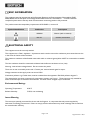
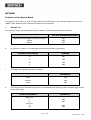
PEGASUS R
MODEL 970
User Maintenance Manual/Handbook
Isothermal Technology Limited, Pine Grove, Southport, PR9 9AG, England
Tel: +44 (0)1704 543830 Fax: +44 (0)1704 544799 Internet: www.isotech.co.uk E-mail: [email protected]
The company is always willing to give technical advice and assistance where appropriate. Equally, because of the programme of continual
development and improvement we reserve the right to amend or alter characteristics and design without prior notice. This publication is for
information only
Page 1 of 24
Pegasus R Iss.07 – 08/13
CONTENTS
CONTENTS ....................................................................................................................................................................................... 2
GUARANTEE...................................................................................................................................................................................... 3
CAUTIONARY NOTE........................................................................................................................................................................ 4
EMC INFORMATION ........................................................................................................................................................................ 5
ELECTRICAL SAFETY ........................................................................................................................................................................ 5
Environmental Ratings .................................................................................................................................................................. 5
Insert Warning .............................................................................................................................................................................. 5
HEALTH AND SAFETY INSTRUCTIONS ......................................................................................................................................... 6
INTRODUCTION .............................................................................................................................................................................. 7
UNPACKING AND INITIAL INSPECTION ...................................................................................................................................... 7
ELECTRICITY SUPPLY ....................................................................................................................................................................... 7
THE BASIC WORKINGS OF THE PEGASUS .................................................................................................................................... 8
OPERATION ...................................................................................................................................................................................... 8
Altering the Furnace Temperature (Set point) ................................................................................................................................ 8
ASSEMBLING THE INSERT ............................................................................................................................................................... 9
INITIAL TESTING............................................................................................................................................................................. 10
CALIBRATION USING THE TEMPERATURE INDICATED ON THE CONTROLLER ................................................................. 11
TUTORIAL: THE USE OF A PEGASUS 'R' CALIBRATED SOURCE TO CALIBRATE RADIATION PYROMETERS ..................... 12
INTRODUCTION ......................................................................................................................................................................... 12
Setting up the Source ................................................................................................................................................................. 12
Using the Source ........................................................................................................................................................................ 12
Requirements for an Optical Bench (See Figure 19071) ............................................................................................................ 12
A Typical Calibration/Evaluation of an Industrial Pyrometer ..................................................................................................... 13
DESCRIPTION............................................................................................................................................................................... 13
BACK & FORTH ............................................................................................................................................................................ 13
HEIGHT ......................................................................................................................................................................................... 13
LATERAL MOVEMENT ................................................................................................................................................................. 13
METHOD ...................................................................................................................................................................................... 14
Evaluation of the Optical Bench ................................................................................................................................................. 14
Audit Calibration ........................................................................................................................................................................ 15
Table 1: Calibration Results ....................................................................................................................................................... 16
USING THE PC INTERFACE ........................................................................................................................................................... 17
CONNECTIONS ........................................................................................................................................................................... 17
CAL NOTEPAD................................................................................................................................................................................ 18
DEVELOPMENT ........................................................................................................................................................................... 18
HOW TO INSTALL CAL NOTEPAD ........................................................................................................................................... 19
PROTOCOL .................................................................................................................................................................................. 19
FIGURE 1: PEGASUS 'R' PANEL LAYOUT AND FUNCTIONS ...................................................................................................... 20
FIGURE 19071 .................................................................................................................................................................................. 21
APPENDIX 1: TROUBLE SHOOTING ............................................................................................................................................ 24
TEMPERATURE UNSTABLE ......................................................................................................................................................... 24
UNIT FAILS TO HEAT .................................................................................................................................................................. 24
CONTROLLER DISPLAY UNUSUAL ........................................................................................................................................... 24
HEATER FAIL ON ......................................................................................................................................................................... 24
WARM UP TIME UNUSUALLY LONG ........................................................................................................................................ 24
INDICATOR MISBEHAVES ('S' ONLY) ......................................................................................................................................... 24
MAINTENANCE .............................................................................................................................................................................. 24
Page 2 of 24
Pegasus R Iss.07 – 08/13
GUARANTEE
This instrument has been manufactured to exacting standards and is guaranteed for twelve months against electrical
break-down or mechanical failure caused through defective material or workmanship, provided the failure is not the
result of misuse. In the event of failure covered by this guarantee, the instrument must be returned, carriage paid, to
the supplier for examination and will be replaced or repaired at our option.
FRAGILE CERAMIC AND/OR GLASS PARTS ARE NOT COVERED BY THIS GUARANTEE
INTERFERENCE WITH OR FAILURE TO PROPERLY MAINTAIN THIS INSTRUMENT MAY INVALIDATE THIS
GUARANTEE
RECOMMENDATION
The life of your ISOTECH Instrument will be prolonged if regular maintenance and cleaning to remove general dust
and debris is carried out.
ISOTHERMAL TECHNOLOGY LTD.
PINE GROVE, SOUTHPORT
PR9 9AG, ENGLAND
TEL: +44 (0) 1704 543830/544611
FAX: +44 (0)1704) 544799
The company is always willing to give technical advice and assistance where appropriate. Equally, because of the
programme of continual development and improvement we reserve the right to amend or alter characteristics and
design without prior notice. This publication is for information only.
Page 3 of 24
Pegasus R Iss.07 – 08/13
CAUTIONARY NOTE
ISOTECH PRODUCTS ARE INTENDED FOR USE BY TECHNICALLY TRAINED AND COMPETENT
PERSONNEL FAMILIAR WITH GOOD MEASUREMENT PRACTICES.
IT IS EXPECTED THAT PERSONNEL USING THIS EQUIPMENT WILL BE COMPETENT WITH THE
MANAGEMENT OF APPARATUS WHICH MAY BE POWERED OR UNDER EXTREMES OF TEMPERATURE, AND
ARE ABLE TO APPRECIATE THE HAZARDS WHICH MAY BE ASSOCIATED WITH, AND THE PRECAUTIONS
TO BE TAKEN WITH, SUCH EQUIPMENT.
Page 4 of 24
Pegasus R Iss.07 – 08/13
EMC INFORMATION
This product meets the requirements of the European Directive on Electromagnetic Compatibility (EMC)
2004/108/EC and the European Low Voltage Directive BS EN 61010-1 Amendment 1. To ensure emission
compliance please ensure that any serial communications connecting leads are fully screened.
The product meets the susceptibility requirements of EN 50082-1, criterion B.
Symbol Identification
Publication
Description
ISO3864
Caution (refer to manual)
IEC 417
Caution, Hot Surface
ELECTRICAL SAFETY
This equipment must be correctly earthed.
This equipment is a Class 1 Appliance. A protective earth is used to ensure the conductive parts cannot become live
in the event of a failure of the insulation.
The protective conductor of the flexible mains cable which is coloured green/yellow MUST be connected to a suitable
earth.
The blue conductor should be connected to Neutral and the Brown conductor to Live (Line).
Warning: Internal mains voltage hazard. Do not remove the panels.
There are no user serviceable parts inside. Contact your nearest Isotech agent for repair.
Voltage transients on the supply must not exceed 2.5kV.
Conductive pollution e.g. Carbon dust, must be excluded from the apparatus. EN61010 pollution degrees 2
The apparatus has two input connectors for temperature sensors; see Figure 1. These inputs are only suitable for
either a thermocouple or resistance thermometer. No other sensor or signal may be connected.
Environmental Ratings
Operating Temperature
0-50°C
Relative Humidity
5-95%, non condensing
Insert Warning
The inserts are specially processed for the use with the Pegasus. It is important that only inserts supplied by
Isothermal Technology Ltd are used. Failure to comply with this information may result in damage which would not
be covered under warranty.
Page 5 of 24
Pegasus R Iss.07 – 08/13
HEALTH AND SAFETY INSTRUCTIONS
1.
Read this entire manual before use.
2.
Wear appropriate protective clothing.
3.
Operators of this equipment should be adequately trained in the handling of hot and cold items and liquids.
4.
Do not use the apparatus for jobs other than those for which it was designed, i.e. the calibration of
thermometers.
5.
Do not handle the apparatus when it has hot (or cold), unless wearing the appropriate protective clothing and
having the necessary training.
6.
Do not drill, modify or otherwise change the shape of the apparatus.
7.
Do not dismantle the apparatus.
8.
Do not use the apparatus outside its recommended temperature range.
9.
If cased, do not return the apparatus to its carrying case until the unit has cooled.
10.
There are no user serviceable parts inside. Contact your nearest Isotech agent for repair.
11.
Ensure materials, especially flammable materials are kept away from hot parts of the apparatus, to prevent
fire risk.
Page 6 of 24
Pegasus R Iss.07 – 08/13
INTRODUCTION
The Pegasus 'R' has been designed to be rugged and easily maintainable.
By using a proprietary plug-in controller the total electronics package can be replaced in a few minutes. As can be
seen from the parts list, remarkably few components have been used, each of which are easily removed and replaced.
This model provides a volume of constant temperature in which an N.P.L. designed black body source is situated
according to the accompanying assembly drawing. (Fig. 970-20-02)
The temperature required is set on the bottom controller.
The indicator above the controller, when connected to a type R thermocouple positioned centrally at the target
matrix indicates the temperature of the source.
Radiance temperature - that is read by a radiation pyrometer is found from the calibration certificate (if supplied).
The Pegasus model is part of a range of portable calibrators designed and made by ourselves. Please contact us or
visit our website www.isotech.co.uk if you require more information about our other products.
UNPACKING AND INITIAL INSPECTION
Our Packing Department uses custom designed packaging to send out your unit, but as accidents can still happen in
transit, you are advised, after unpacking the unit, to inspect it for any sign of shipping damage, and confirm that your
delivery is in accordance with the packing note. If you find any damage or that part of the delivery is missing notify us
or our agent, and the carrier immediately. Keep the packing, if damaged, for possible inspection by an insurance
assessor.
ELECTRICITY SUPPLY
Before connecting to the electricity supply please familiarise yourself with the parts of the manual relevant to your
model.
Your unit's supply voltage requirement is specified on a plate on the base of the instrument along with the serial
number. All Pegasus instruments will work on an electricity supply frequency of 50Hz or 60Hz. (Consult
temperature controller manual).
The unit's electricity supply cable is colour-coded as follows:COLOUR
Green/yellow
Brown
Blue
FUNCTION
Earth (Ground)
Live (Line)
Neutral
Please ensure that your unit is correctly connected to the electricity supply.
Page 7 of 24
Pegasus R Iss.07 – 08/13
THE BASIC WORKINGS OF THE PEGASUS
The purpose of the Pegasus 'R' model is to provide an adjustable isothermal enclosure for calibration purposes.
The isothermal enclosure consists of a fixed heated furnace.
The heated furnace houses a graded heater winding and the control sensor used by the temperature controller to
sense the furnace temperature. To obtain and maintain a required temperature the controller varies the power to
the heater via a solid state relay.
A fan runs continuously and cools the electronics in the instrument.
OPERATION
Altering the Furnace Temperature (Set point)
1)
Switch on - The controller will briefly show its software version before displaying an indication of the block
temperature.
2)
Momentarily press either the UP or DOWN key once to display the setpoint (desired temperature).
3)
To alter the value press and hold the UP key to raise the value or the DOWN key to the lower the value.
4)
The display will return to show the nominal block temperature when no key is pressed for 0.5 second.
The other controller functions are hidden from the operator. The values are pre-set and should not be
changed.
Page 8 of 24
Pegasus R Iss.07 – 08/13
ASSEMBLING THE INSERT
Where the unit is to be used with a standard or special insert, the insert ceramics must be assembled as per the
drawing below.
1.
Ensure furnace is cool.
2.
Slide the long ceramic insulator (970-01-03C) down the furnace tube so that it rests on the base.
3.
Carefully lower the smaller ceramic (970-01-03B) inside the furnace to rest on the lower ceramic.
4.
Load the blackbody (970-01-02) with the reference thermocouple installed (970-20-01).
5.
Finally add the upper top ceramic insulator (970-01-03A).
Page 9 of 24
Pegasus R Iss.07 – 08/13
INITIAL TESTING
This unit was tested before despatch to you but please check its operation as outlined below and in Appendix 1.
After connecting the Pegasus 'R' to the electricity supply, the temperature controller display will show the
temperature of the furnace and the last set-point value. The 'R' controller and indicator both go through a self-test
sequence first. The fan on the side panel should be heard running.
Change the set-point to 200 C and observe that the furnace temperature rises and settles to this value. For the 'R';
place a thermometer in the source and connect it to the suitably configured (see 'R' procedure) indicator. Confirm
that the indicator agrees within a few degrees of the controller.
Your unit should have performed as described above and can now be used for calibration.
If any problems or faults arise during these tests please contact us or our agents for help and advice.
WARNING
To prolong the life of the heater windings the temperature should not be increased by more than in 200 C
increments, allow the temperature controller to indicate it as at the fixed point before resetting the next temperature
increment.
The controller's function settings should not normally require any changes from what we have set them to.
Page 10 of 24
Pegasus R Iss.07 – 08/13
CALIBRATION USING THE TEMPERATURE INDICATED ON THE
CONTROLLER
1.
Remove the Pegasus 'R' from its case and visually inspect it for any damage it may have sustained since it was
last used. Insert the black body source assembly (see fig 970-20-02) into the furnace tube with the ceramic
insulators.
2.
Connect the Pegasus 'R' to a suitable power supply and set the controller to the required temperature (see
the controller's manual for details and Fig 1).
3.
Wait for the temperature to stabilise.
4.
When the temperature indicated by the controller and the output of the thermometer are both stable (see
specification for typical values) record three sets of readings over a period of about six minutes. Check that
these readings are consistent and then calculate their average values.
5.
The Pegasus 'R' has itself been calibrated, correct the average values accordingly.
6.
Reset the controller and/or repeat the calibration for another thermometer.
7.
When the calibration is complete, reset the controller to 0 C and wait until the unit has cooled to below
400 C before moving the Pegasus to a new location. The Pegasus must be cooled to about 100 C before it
can be put back into its carrying case.
Page 11 of 24
Pegasus R Iss.07 – 08/13
TUTORIAL: THE USE OF A PEGASUS 'R' CALIBRATED SOURCE TO
CALIBRATE RADIATION PYROMETERS
INTRODUCTION
The Pegasus 'R' is designed as a source for the calibration of radiation pyrometers over the range 200 C to 1200 C.
Most users of radiation pyrometers are unfamiliar with the procedures for calibration and the tutorial below is
intended to help new users. It is meant only as a guide and not as a gospel.
Setting up the Source
The Pegasus 'R' comprises a small tube furnace of diameter approximately 35mm.
Separately is a 3 part assembly plus a thermocouple which assembles into the tube furnace as diagram 970-20-02.
The thermocouple, as can be seen from diagram 970-20-01 has a right-angled bend in the ceramic sheath at its tip.
This bend is to facilitate insertion of the thermocouple tip into the cavity at the base of the black body target (970-0102) see diagram 970-20-02. (The internal wires of the thermocouple may be visible at the bend in the ceramic but this
is normal - the thermocouple is not broken). Once the tip of the thermocouple has been situated in the cavity of the
target, the target is assembled into the well of the Pegasus. The insulation piece 970-01-03 (as shown in diagram 97020-02) is then assembled into the Pegasus with the thermocouple alongside (which sits in the groove in the insulation
piece).
The thermocouple is connected to an indicator situated on the front of the Pegasus 'R' as shown on figure 1. The size
and shape of the insulation and the position of the thermocouple are all important and if the assembly is modified, the
calibration certificate may become invalid. Having assembled the Pegasus 'R' a temperature is set (see commissioning
later in this document).
3 steps are required to obtain the radiance temperature of the source:
a) Set the required temperature on the controller.
b) Take the reading on the indicator.
c) Add or subtract the correction from the calibration sheet, (correction may be considered to vary linearly between
calibration points) to obtain the radiance temperature.
For example: Say 1000 C is the controller set point. The indicated value might be 991 C. If the calibration certificate
is consulted, the radiance temperature is noted to be 10 C lower than the indicated value i.e. 981 C.
Using the Source
The simplest and least accurate method of using the source is to set its temperature, calculate its radiance
temperature as described above and point the radiation pyrometer at the source.
More usually a small optical bench is built to accurately hold the source and pyrometer enabling proper alignment to
take place.
Requirements for an Optical Bench (See Figure 19071)
An optical bench can be a very expensive piece of apparatus of precision ground components, or a very basic piece of
equipment built onto a wooden board.
Page 12 of 24
Pegasus R Iss.07 – 08/13
For normal industrial pyrometers a simple bench is quite adequate. My suggestion is a slide piece to enable
pyrometers of varying focal length to be calibrated and a holder for the pyrometer which allows 2 freedom of
movement i.e. height and lateral position.
A Typical Calibration/Evaluation of an Industrial Pyrometer
A typical calibration sequence for a optical pyrometer is given below adapted from our UKAS submission.
DESCRIPTION
A calibrated target is used as the source of information, together with the certificate of calibration - see ref NPL
12317/91/001 dated 15/05/1991.
An optical bench was built (see drawing 19071) which allowed an optical pyrometer to be calibrated.
The optical bench allowed 3 freedom of movements:-
BACK & FORTH
The distance to the optical pyrometer transfer standard from the rear of the Black Body is 750mm. An optical bench
allows the optical pyrometer transfer standard to be moved from 660mm to 1000mm.
HEIGHT
The height of the optical pyrometer can be adjusted by -10, +15mm from the normal position
LATERAL MOVEMENT
The optical pyrometer can be moved sideways by -10, +15mm from the normal position.
Page 13 of 24
Pegasus R Iss.07 – 08/13
METHOD
Evaluation of the Optical Bench
The Pegasus 'R' item was set up in the 'normal' position as described above. The controller temperature was set to
1000 C. After stabilisation the 3 freedom of movement were evaluated.
a.
Back & Forth
The optical pyrometer was moved back & forth by 100mm. The following readings were obtained.
OPTICAL PYROMETER READING
650mm from rear of target to optical pyrometer
750mm
850mm
b.
At a distance of 750mm. The focal length of the optical pyrometer was changed.
METRES FOCAL LENGTH
c.
984
983
983
READING
.75
983
.8
983
.85
983
.9
983
The height of the optical pyrometer was altered
READING C
d.
-2mm
982
Normal
983
+2mm
982
The lateral position of the optical pyrometer was adjusted and the optical pyrometer rotated to align with the
centre of the target.
LATERAL MOVEMENT
READING C
Right (mm)
5
10
Left (mm)
5
10
983
983
983
983
Page 14 of 24
Pegasus R Iss.07 – 08/13
Audit Calibration
Having established confidence in the optical bench system and the optical pyrometer.
The calibrated source, Pegasus 'R' was set to the first calibration temperature and allowed to stabilise. The optical
pyrometer was placed in its holder as shown in fig. 19071.
The controller temperature, the indicated source temperature and the optical pyrometer temperatures were noted.
From the calibration certificate the radiance temperature was calibrated.
The difference between the radiance temperature and the optical pyrometer temperature gives the error of the
optical pyrometer reading within the uncertainty stated.
Results obtained at 5 temperatures are tabulated over-leaf.
Page 15 of 24
Pegasus R Iss.07 – 08/13
Table 1: Calibration Results
RADIANCE
TEMP. READING
CORRECTED
FROM NPL CERT
C
PEGASUS R
CONTROLLER
TEMP C
T/C INDICATED
TEMP SOURCE
OPTICAL
PYROMETER
READING C
Standard
220
222
220
226
Standard
440
442
438
448.8
Standard
660
660
656
662
Standard
800
797
793
795
Standard
1000
991
986
981
Page 16 of 24
Pegasus R Iss.07 – 08/13
USING THE PC INTERFACE
The PLUS models include an RS422 PC interface and a special converter cable that allows use with a standard RS232
port. When using the bath with an RS232 port it is essential that this converter cable is used. Replacement cables are
available from Isotech, part number ISO-232-432. A further lead is available as an option, Part Number ISO-422-422
lead which permits up to 5 instruments to be daisy chained together.
The benefit of this approach is that a number of calibration baths may be connected together in a "daisy chain"
configuration - and then linked to a single RS232, see diagram.
Note: The RS 422 standard specifies a maximum lead length of 1200M (4000ft). A true RS422 port will be required to
realise such lead lengths. The Isotech conversion leads are suitable for maximum combined lead lengths of 10M that is
adequate for most applications.
CONNECTIONS
For RS232 use simply connect the Isotech cable, a 9 to 25 pin converter is included to suit PCs with a 25 pin serial
converter.
RS422 Connections
Pin
4
5
8
9
1
Connection
Tx+ A
Tx- B
Rx+ A
Rx- B
Common
Page 17 of 24
Pegasus R Iss.07 – 08/13
CAL NOTEPAD
Cal Notepad can be used can be used to log and display values from the Dry Blocks and an optional temperature
indicator such as the milliK or TTI-10. The software requires Windows 9X, XP, a minimum of 5Mb of free hard drive
space and free serial ports for the instruments to be connected.
DEVELOPMENT
Cal NotePad was developed by Isothermal Technology using LabVIEW from National Instruments. The license details
are shown on the download page and in the Cal Notepad manual.
Page 18 of 24
Pegasus R Iss.07 – 08/13
HOW TO INSTALL CAL NOTEPAD
1.
Download the ZIP from http://www.isotech.co.uk/downloads (7.6Mb)
2.
Extract the files to a temporary folder
3.
Run setup.exe
4.
Follow the prompts which will install the application, a user manual with setup information and the necessary
LabVIEW run time support files.
5.
Should you ever need to uninstall the software then use the Add/Remove Programs option from the Control
Panel.
PROTOCOL
The instruments use the "Modbus Protocol"
If required, e.g. for writing custom software the technical details are available from our Document Library at
http://www.isotech.co.uk
Page 19 of 24
Pegasus R Iss.07 – 08/13
FIGURE 1: PEGASUS 'R' PANEL LAYOUT AND FUNCTIONS
1.
T/C SOCKET
2.
INDICATOR
3.
CONTROLLER
4.
CALIBRATION AREA
Page 20 of 24
Pegasus R Iss.07 – 08/13
FIGURE 19071
Page 21 of 24
Pegasus R Iss.07 – 08/13
Page 22 of 24
Pegasus R Iss.07 – 08/13
Page 23 of 24
Pegasus R Iss.07 – 08/13
APPENDIX 1: TROUBLE SHOOTING
TEMPERATURE UNSTABLE
Controller has incorrect parameters set; reset to standard. If still unstable try the self-tune option. Check the
electricity supply is stable.
UNIT FAILS TO HEAT
Check controller is set correctly. If the output indicator on the controller is lit the relay should operate the heater. If
the output indicator stays off it is likely the controller is set incorrectly.
CONTROLLER DISPLAY UNUSUAL
Error or system message. Refer to Isotech or your local Agent.
HEATER FAIL ON
If the temperature of the block increases rapidly with the controller output staying off the relay and sensor are
suspect. Do not use the unit, contact Isotech or your agent.
WARM UP TIME UNUSUALLY LONG
Controller set incorrectly, failure of one heater, or cooling fan permanently on. Check controller settings.
The fan on the side panel should always be on.
INDICATOR MISBEHAVES ('S' ONLY)
Wrong configuration code entered, check against table.
If SnSr FAIL is displayed, check probe connections. If displayed with no probe connected, check that the link is fitted
correctly and that the configuration is for a thermocouple type.
MAINTENANCE
The only moving part is the fan. It has sealed-for-life bearings. Depending on the environment in which it is used,
periodic cleaning of them and the inside of the case is recommended. Cleaning may be accomplished by the use of a
small dry paint brush.
The instrument should be periodically checked to ensure it is in good order both mechanically and electrically.
Page 24 of 24
Pegasus R Iss.07 – 08/13