1
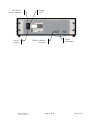
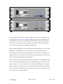
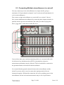
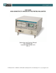
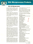
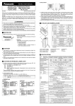
User Manual
Applies to:
Firmware version 1.00+
Isothermal Technology Limited
Pine Grove
Southport
Merseyside
PR9 9AG
T: +44 (0)1704 543830
F: +44 (0)1701 544799
E: [email protected]
W: www.isotech.co.uk
CONTENTS
1
INTRODUCTION ............................................................................... 4
1.1
Unpacking ........................................................................................................................5
1.2
Safety ................................................................................................................................5
1.3
A Quick Tour of Your microsKanner ...........................................................................7
2
USING YOUR MICROSKANNER ................................................... 10
2.1
Powering Up Your microsKanner ...............................................................................10
2.2
Connecting a Single microsKanner to a microK ........................................................11
2.3
Connecting Multiple microsKanners to a microK .....................................................13
3
CONNECTING THERMOMETER SENSORS ................................. 16
3.1
The “Cable-Pod” Connectors.......................................................................................16
3.2
Connecting PRTs (4-wire) ............................................................................................16
3.3
Connecting PRTs (3-wire) ............................................................................................17
3.4
Connecting PRTs (2-wire) ............................................................................................18
3.5
Connecting Thermocouples (external Ice Point or WTP)..........................................19
3.6
Connecting Thermocouples (using RJ compensation) ...............................................19
3.7
Connecting Thermistors ...............................................................................................20
4
GOOD PRACTICE GUIDELINES.................................................... 22
4.1
Looking After Your microsKanner .............................................................................22
4.2
Making a Good Electrical Measurement ....................................................................22
5
THE MICROSKANNER TECHNOLOGY......................................... 25
5.1
Buffered Switching........................................................................................................25
5.2
Minimising Thermal EMFs ..........................................................................................26
5.3
Solid-State Switching ....................................................................................................26
5.4
Eliminating Self-Heating Effects..................................................................................27
6
CALIBRATION ................................................................................ 28
6.1
Before You Check the Calibration...............................................................................28
©
Page 2 of 48
Issue: 1.01
6.2
Checking the Keep-Warm Current Sources............................................................... 28
6.3
Adjusting the Keep-Warm Current Sources .............................................................. 29
6.4
Checking the Zero Voltage Offsets.............................................................................. 29
6.5
Adjusting the Zero Voltage Offsets ............................................................................. 31
7
7.1
7.2
RS232 INTERFACE ........................................................................ 32
Establishing an RS232 Connection.............................................................................. 32
SCPI Command Set ...................................................................................................... 34
7.2.1
7.2.2
7.2.3
7.2.4
7.2.5
7.2.6
7.2.7
SCPI Command Structure ............................................................35
SCPI Numeric Suffices ................................................................36
Parameters ....................................................................................36
Units .............................................................................................37
Controlling the microsKanner Using the RS232 Port..................37
Terminology – Inputs and Channels ............................................38
SCPI Commands ..........................................................................39
8
SPECIFICATION ............................................................................. 46
9
APPROVALS .................................................................................. 47
9.1
CE Declaration.............................................................................................................. 47
9.2
FCC Statement.............................................................................................................. 47
9.3
Standards Applied ........................................................................................................ 48
©
Page 3 of 48
Issue: 1.01
1 Introduction
The microsKanner multiplexer can be connected to your microK Precision
Thermometry Bridge to increase the number of input channels. Each multiplexer
has 10 input channels and up to 9 microsKanners can be connected to a microK,
providing you with up to 92 measurement/reference channels for each microK
Bridge. The microsKanner includes features that enable you to make the most
accurate measurements possible with your microK Bridge. When you connect
the multiplexer to your microK, the additional channels appear automatically on
your microK Bridge and can be configured and used in exactly the same way as
the microK’s own input channels, so you can get on with making measurements
rather than worrying about how to control your multiplexer.
The microsKanner is not simply a switch-box. It duplicates the input circuit of a
microK Bridge for each of its input channels so that there is no additional
uncertainty on measurements made through the multiplexer compared with those
made directly by the bridge. Each channel is also equipped with an individually
programmable keep-warm current that can be used to maintain the power in a
PRT (Platinum Resistance Thermometer) when it is not being measured so as to
eliminate the uncertainty that would otherwise arise from self-heating of the
thermometer.
The microsKanner uses the same low thermal-EMF connector system (CablePod™ tellurium-copper connectors) as the microK Bridge. It is also capable of
reversing each input channel immediately behind the voltage input terminals to
provide thermal-EMF compensation. When the microK Bridge detects that it is
connected to a microsKanner, it automatically changes from making input
reversal at its own input terminals to making the reversal at the microsKanner
inputs in order to ensure that there is no additional uncertainty when measuring
thermocouples via the microsKanner. Any thermal EMFs in the analogue
connections between the microK and the microsKanner are eliminated by this
reversal strategy, so that there is no difference in measurement uncertainty
©
Page 4 of 48
Issue: 1.01
between measurements made via the microsKanner and those made directly with
your microK.
The microsKanner uses the latest semiconductor technology to implement
channel switching rather than the relays that are commonly used in multiplexers.
This completely solid-state design makes the microsKanner highly reliable.
This manual provides a comprehensive guide to using the multiplexer. We
recognise that you will probably not wish to read it through at this time so
suggest you read the safety section below, turn to Section 2.2 (to learn how to
connect you microsKanner to your microK) and then refer back to the manual
using the list of contents to find additional information as required.
1.1 Unpacking
Your microsKanner product should comprise the following items:
microsKanner multiplexer
power lead suitable for your country
RS232 null modem cable
analogue link cable
this user manual
If any item is missing or damaged, please report this immediately to your
supplier. If possible, we recommend that you retain the packaging material in
case you need to return the instrument for calibration or service since it has been
designed to ensure that your microsKanner is properly protected during
transportation.
1.2 Safety
The microsKanner is a precision instrument, designed for use in a laboratory. It
complies with the requirements of safety standard EN61010-1 (2001) and is
therefore safe to use in laboratory or light industrial environments. It is not
intended for use outdoors or in extreme environments (refer to specification in
Section 8).
©
Page 5 of 48
Issue: 1.01
The microsKanner is likely to be connected to thermometer sensors in use and
!
the operator should take care to ensure that the complete system is safe. For
example, metal sheathed thermometers may be connected to the microsKanner
and then placed in a furnace powered from a 230V electrical supply. Single fault
conditions in such a furnace could lead to the thermometer wires and therefore
the front terminals of the microsKanner becoming electrically live and therefore
a hazard to the operator. Suitable precautions should be taken, such as using an
isolating transformer in the supply to such a furnace. If you require further advice
on safety issues, please contact Isothermal Technology or one of our appointed
distributors - we have extensive experience of thermometry and can provide
advice and equipment to help you.
Retain these instructions. Use only as specified in these operating instructions or
the intrinsic protection may be impaired.
Please observe the following safety precautions:
Do not use your microsKanner if it is damaged
Only connect to an earthed supply socket. THIS UNIT IS CLASS 1
CONSTRUCTION AND MUST BE EARTHED!
Connect only to a power supply with a voltage corresponding to that on
the rating plate
This equipment is for indoor use and will meet its performance figures
within an ambient temperature range of 5°C to 40°C with maximum
relative humidity of 80% for temperatures up to 31ºC decreasing linearly
to 50% RH at 40ºC
Equipment is for operation at installation category II (transient voltages)
and pollution degree II in accordance with IEC 664 at altitudes up to
2000 metres
Before replacing a fuse, DISCONNECT THE EQUIPMENT FROM THE
ELECTRICAL SUPPLY
The fuse is contained in the IEC socket on the rear panel. It must only be
replaced with a fuse of the type and rating marked on the rear panel
If a replacement fuse fails immediately, contact your local service agent.
DO NOT replace with a higher value
Always use the power cord supplied. Your sales outlet can provide a lead
suitable for your country
This equipment is for use in moderate climates only. NEVER use the
equipment in damp or wet conditions
Avoid excessive heat, humidity, dust & vibration
Do not place liquid filled containers on the equipment
Do not use where the equipment (or any associated accessories) may be
subjected to dripping or splashing liquids
©
Page 6 of 48
Issue: 1.01
Ensure that the power switch is easily accessible to allow the unit to be
switched off
The equipment weighs 13kg; use the handles provided. Always
disconnect the equipment from the electrical supply and any ancillary
units before moving
Ensure that tabletop equipment is placed on a solid, level surface, which
is able to support its weight (and that of any attached accessories)
Ensure all cables and wires are routed safely to avoid tripping: also to
avoid sharp bends and pinches
Clean only with a damp cloth. Do not wet or allow moisture to penetrate
the unit. Do not use solvents. See section 4.1 for details of cleaning
procedure
The product should be subjected to regular in-service inspections as
required by local regulations; a yearly interval is suggested
Verify that the supply cord set is undamaged and that the enclosure is
bonded to protective earth. Do not apply earth test currents to any front
panel terminal nor to the shrouds of the USB or RS232 connectors
The product is designed to comply with EN 61010-1 and can be flash
tested. It is fitted with radio frequency interference suppressors.
Therefore it is recommended that only a D.C. test be performed
Performing flash tests repeatedly can damage insulation
This equipment contains no user-serviceable parts. Refer all repairs to
qualified service personnel. Contact Isothermal Technology or one of our
appointed distributors for details of approved service outlets
1.3 A Quick Tour of Your microsKanner
On the front panel of your microsKanner you will find the terminals for the ten
inputs channels (five terminals per channel), the output terminals for connection
to your microK (five terminals) and 10 red LEDs that indicate when a channel is
selected:
©
Page 7 of 48
Issue: 1.01
Output
Terminals
Indicator
LED
Input
Terminals
Input/Output Terminals: The terminals accept 4mm plugs, spades or bare
wires. The current (I) and voltage sense (V) terminals are spaced on ¾” centres
so that standard BNC to 4mm adaptors (not supplied) can be used to connect to
thermometer sensors that have BNC terminations
The contact material for the connectors is gold plated tellurium-copper, offering
extremely low thermal EMFs when connected to copper wires/connectors. This
is essential when using precision thermocouples.
On the rear panel of your microsKanner you will find the electrical supply
connector/power switch/fuse module. There are also two RS232 ports that allow
you to connect the multiplexer to your microK Bridge, other microsKanners or a
PC in order to control the whole measurement system using your own software
(see section 7). The command protocol employs the widely used SCPI format
(see section 7.2 for details).
©
Page 8 of 48
Issue: 1.01
IEC 60320-1
Power Connector
On/Off
Switch
©
Supply
Fuse
USB-B Connector
(not used)
Page 9 of 48
RS232
Connectors
Issue: 1.01
2 Using your microsKanner
Your microsKanner is very easy to use, simply connect it to your microK Bridge
(analogue and RS232 connections) and apply power to both instruments. On
power-up, the microK ‘discovers’ any microsKanners connected to it and assigns
channel numbers to each input. These additional channels then appear in your
microK’s list of channels and can be configured and used in the same was as the
existing channels on the bridge.
The automatic discovery process only takes place during initialisation of the
microK software and requires the RS232 connection(s) to be present (see
sections 2.2 or 2.3). If you connect or power the microsKanner after the microK
software has initialised (at the initial screen with the Resume button, or later),
press the Restart Software button on the Instrument tab of the microK to reinvoke the discovery process.
A microsKanner will only work with a microK Bridge that is running with
!
firmware version 3.10 or above and software version 1.3.15 or above. The
firmware and software versions are shown on the microK Bridge in the opening
screen (with the Resume button). If your microK is running with older firmware
or software, please contact Isothermal Technology or one of our appointed
distributors to arrange an upgrade. The hardware on all microKs is compatible
with microsKanner multiplexers.
2.1 Powering Up Your microsKanner
The microsKanner operates on any standard AC electrical supply (88-264V RMS
at 47-63Hz) so unless your supply is unusual you can simply use the power cord
provided to connect your microsKanner to a suitable electrical outlet.
The power switch is located at the rear of the instrument, immediately below the
IEC connector. When you turn your microsKanner on, all the Channel LEDs on
the front panel will flash momentarily and then be extinguished. Your
microsKanner is now ready for use.
©
Page 10 of 48
Issue: 1.01
2.2 Connecting a Single microsKanner to a microK
Connect the five Output Terminals on the microsKanner to the corresponding
input terminals on Channel 1 of the microK, using the link cable provided:
If you wish to make your own interconnecting cable, use a screened cable with
low dielectric loss insulation such as PTFE or polyethylene (otherwise
measurement performance may be affected). The screen should be connected to
the ground terminals of the microK and microsKanner.
It is essential that the ground connection between the microsKanner and the
microK is present as this is used to connect the signal grounds of the two
instruments together. Without this connection, the active guarding system in the
microsKanner will not work and measurements may be out of specification.
Connect the RS232 port on the rear of the microK to either of the RS232 ports on
the microsKanner (it does not matter which port is used as they are completely
interchangeable) using the null modem cable provided (see section 7.1 if you
wish to make your own cable):
©
Page 11 of 48
Issue: 1.01
If the software on the microK is already running, restart it by cycling the power
or pressing the Restart Software button on the Instrument tab. This initiates the
automatic discovery process so that the microK can detect any microsKanners
connected to it and assign channel numbers. The microK will disable Channel 1,
since it is always used as the expansion channel input.
With a single microsKanner, the microK assigns channel numbers 10 to 19 to the
multiplexer. The numbers (0 to 9) below each set of input terminals on the
microsKanner help to identify the terminals for each Channel (for example, the
input marked as 4 is Channel 14). The LED (by the top terminal) will light when
measurements are being made on that channel.
If you want to control the measurement system (microK and microsKanner) from
a PC, connect the unused RS232 port on the microsKanner to a PC using a null
modem cable. You can still communicate with the microK Bridge even though
there is no physical connection to it as the microsKanners will relay commands
from the PC to the microK and will relay back responses from the microK to the
PC (see section 7 for further details).
©
Page 12 of 48
Issue: 1.01
2.3 Connecting Multiple microsKanners to a microK
You may connect up to nine microsKanners to a single microK, giving a
maximum of 92 input channels (channels 2 and 3 on the microK and channels 10
to 99 via microsKanners).
First connect a single microsKanner to your microK (see section 2.2 above).
Now connect additional microsKanners by connecting their Output terminals (in
parallel) with the previous microsKanner (the cables provided use plugs that
allow “piggy-back” connection to make this easy):
If you wish to make your own interconnecting cable, use a screened cable with
low dielectric loss insulation such as PTFE or polyethylene (otherwise
measurement performance may be affected). The screen should be connected to
the ground terminals of the microK and microsKanner.
It is essential that the ground connection between the microsKanner and the
microK is present as this is used to connect the signal grounds of the two
instruments together. Without this connection, the active guarding system in the
microsKanner will not work and measurements may be out of specification.
©
Page 13 of 48
Issue: 1.01
Connect the RS232 port on the rear of the additional microsKanners to the
unused RS232 port on the previous microsKanner using the null modem cable
provided to form a ‘daisy-chain’ arrangement (see section 7.1 if you wish to
make your own cable). The RS232 ports on the microsKanner are completely
interchangeable, so it does not matter which is used to connect to the next
microsKanner or the microK in the system:
If the software on the microK is already running, restart it by cycling the power
or pressing the Restart Software button on the Instrument tab. This initiates the
automatic discovery process so that the microK can detect any microsKanners
connected to it and assign channel numbers. The microK will disable Channel 1,
since it is always used as the expansion channel input.
©
Page 14 of 48
Issue: 1.01
With multiple microsKanners, the microK assigns channel numbers 10 to 19 to
the multiplexer connected directly to it. It then assigns channels numbers 20-29
to the next multiplexer and so on. This means that the channel marked 7 on the
third microsKanner in the ‘daisy-chain’ of RS232 connections will be assigned
channel number 37. The LED (by the top terminal) will light when
measurements are being made on that channel.
If you want to control the measurement system (microK and microsKanners)
from a PC, connect the unused RS232 port on the microsKanner at the end of the
‘daisy-chain’ to a PC using a null modem cable. You can still communicate with
the microK Bridge even though there is no physical connection to it as the
microsKanners will relay commands from the PC to the microK and will relay
back responses from the microK to the PC (see section 7 for further details).
©
Page 15 of 48
Issue: 1.01
3 Connecting Thermometer Sensors
3.1 The “Cable-Pod” Connectors
The Eichmann “Cable-Pod”™ connectors used on the microK have gold-plated
tellurium-copper contacts. These generate exceptionally low thermal EMFs when
connected to the copper terminations used on standards grade thermocouples.
When using your microsKanner to measure the voltage from a thermocouple, use
bare-wire connections directly to the “Cable-Pod”™ connectors. Do not use
plugs (even low-thermal-EMF types) in order to avoid excessive thermal-EMFs.
The connectors accept 4mm plugs, bare wires or spade terminations.
Additionally, they are spaced on 19mm (¾”) pitch so that they can be used with
standard 4mm-to-BNC adaptors (not supplied) for connecting to BNC terminated
SPRTs. The mechanism is designed so that the clamping surface does not rotate
as it clamps the wire in order to avoid damaging it.
The “Cable-Pod”™ mechanism is made from a high strength polymer but
nonetheless may be subject to mechanical damage if the connectors are over
!
tightened. Please tighten the terminals to a light “finger-tight” level in order to
ensure that they are not subject to undue wear or premature failure. This is all
that is required electrically – do not try to use the connector to provide strain
relief or tension a cable.
3.2 Connecting PRTs (4-wire)
The resistance measurement system of your microsKanner and microK is
optimised for high accuracy, 4-wire resistance measurement. The PRT should be
connected to the chosen input channel in accordance with the schematic shown
on the microsKanner’s front panel, as follows:
©
Page 16 of 48
Issue: 1.01
Screen
I
SPRT
I
V
V
The top terminal should be connected to the screen of the SPRT’s lead (where
present) to minimise electrical noise picked up by the wires.
3.3 Connecting PRTs (3-wire)
The microsKanner and microK can be connected to 3-wire PRTs, although they
will not automatically compensate for cable resistance. The two red terminals
should be connected together and then connected to the ‘single’ end of the 3-wire
PRT as follows:
Screen
I
I
V
V
The connection to the ‘single’ end of the 3-wire PRT should be short (have a low
resistance) in order to minimise the effect of lead resistance on the measurement.
The top terminal should be connected to the screen of the PRT’s lead (where
present) to minimise electrical noise picked up by the wires.
©
Page 17 of 48
Issue: 1.01
3.4 Connecting PRTs (2-wire)
The microsKanner and microK can be connected to 2-wire PRTs. The two red
and two black measurement terminals should be connected together and then
connected to the PRT as follows:
Screen
I
I
PRT
V
V
The connections to the PRT should be short (low resistance) in order to minimise
the effect of lead resistance on the measurement. Alternatively, the connections
can use remote sensing (using the 4-wire measurement capability of the microK)
to eliminate the effect of lead resistance completely. In this arrangement, the
current and voltage sense connections are kept separate and are only joined close
to the PRT:
Screen
I
I
V
V
The top terminal should be connected to the screen of the PRT’s lead (where
present) to minimise electrical noise picked up by the wires.
©
Page 18 of 48
Issue: 1.01
3.5 Connecting Thermocouples (external Ice Point or
WTP)
The measurement system of your microsKanner and microK uses active
guarding. As a result, the voltage measurement system is floating until it is
connected to the sense current terminals. In order to measure the voltage on a
thermocouple, the two current terminals should be connected to each other and to
the red voltage sense terminal:
Screen
I
I
Thermocouple
V
V
Measurement
Junction
Reference
Junction
The top terminal should be connected to the screen of the thermocouple’s lead
(where present) to minimise electrical noise picked up by the wires.
The most accurate thermocouple measurements are made with the reference
junction immersed in an ice-point bath (or water triple-point). The microK
supports this arrangement by allowing you to specify the temperature of the
reference junction as 0°C or 0.01°C (see microK manual for details).
3.6 Connecting Thermocouples (using RJ
compensation)
It is possible to measure the temperature of the reference junction and
compensate for the associated EMF at this junction. The reference junction can
be measured using a PRT or thermistor connected to another measurement
channel:
©
Page 19 of 48
Issue: 1.01
Screen
Screen
I
I
I
I
V
V
V
V
Thermocouple
Measurement
Junction
Reference
Junction
PRT
The top terminals should be connected to the screens of the PRT and
thermocouple leads (where present) to minimise electrical noise picked up by the
wires.
The microK supports thus arrangement by allowing you to use a temperature
measured by another input channel as the reference junction temperature. This
technique is less accurate than using an ice-point (or water triple-point) due to
the additional uncertainties associated with the PRT used to monitor the
reference junction and any temperature gradients that result in a difference
between the temperature of the PRT and the reference junction.
3.7 Connecting Thermistors
The microsKanner and microK can be connected to thermistors using the same
arrangement as for 2-wire PRTs (see section 3.4):
©
Page 20 of 48
Issue: 1.01
Screen
I
I
V
THERMISTOR
V
Because the resistance of thermistors used for temperature measurement is much
higher than for PRTs, lead resistance is not normally a problem.
Use an external reference resistor with thermistors since the resistance of the
internal standards is too low. Thermistors have much higher temperature
coefficients than PRT, so the tolerances on the reference resistor are
correspondingly less demanding, making them relatively inexpensive.
The top terminal should be connected to the screen of the thermistor’s lead
(where present) to minimise electrical noise picked up by the wires. The high
resistance of thermistors makes them more prone to picking up electrical noise, it
is therefore even more important to use a screened cable and connect this to the
screen terminal on the microsKanner than when using PRTs.
©
Page 21 of 48
Issue: 1.01
4 Good Practice Guidelines
4.1 Looking After Your microsKanner
Your microsKanner is a precision electronic instrument intended for indoor use
in a laboratory or office environment. Nonetheless, it has been designed to be as
robust as practical and will provide many years of service, provided it is properly
maintained.
The only parts of the microsKanner that require routine calibration checks are the
keep-warm currents and offset voltages for the ten input channels. We
recommend that you check these annually. You can check these yourself using
the procedures given in this manual (see sections 6.2 and 6.4), or we can provide
a traceable calibration of your microsKanner at one of our approved calibration
centres (contact Isothermal Technology or one of our appointed distributors for
details). The microsKanner should require little maintenance between
calibrations other than routine cleaning.
Clean your microsKanner, as required, using either a proprietary cleaner (such as
those sold for cleaning PCs) or water and a little mild liquid soap on a lint-free
cloth. Never use abrasive cleaners (such as ‘cream’ cleaners) on your
microsKanner.
4.2 Making a Good Electrical Measurement
Although the microsKanner and microK are intended for use in temperature
metrology, its base measurements are electrical (resistance or voltage). The
limited sensitivity of PRTs and thermocouples means that in order to achieve
uncertainties at the mK level, we need to make electrical measurements that rival
those of a good electrical metrology laboratory. For example, for a 25Ω SPRT a
1mK temperature uncertainty corresponds to 100µΩ resistance uncertainty. With
a 1mA sense current, this corresponds to a voltage uncertainty of 0.1µV.
The microsKanner and microK are optimised for electromagnetic compatibility
(minimising emissions and maximising immunity). However, since the microK is
©
Page 22 of 48
Issue: 1.01
capable to measuring to such low signal levels it is worthwhile adopting good
electrical measurement practices. Here are a few guidelines:
The most sensitive points are the inputs to the microsKanner or microK
(measuring to better than 0.1µV). Whilst the microsKanner and microK
will work satisfactorily with just a four wire connection to the PRT or
reference resistor (using the voltage sense and current terminals marked
“V” and “I” respectively), it is better to use a screened cable and to
connect the screen to the measurement ground terminal above the input
terminals:
Screen
I
I
SPRT or
Reference Resistor
V
V
The screen should also be connected to the outer sheath of the SPRT (if it
is metal clad) or the case of the reference resistor. The use of screened
cables is more important when the microK is used with thermistors, which
have a higher resistance than PRTs or thermocouples.
Keep the cables to the microsKanner and microK input terminals away
from other cables that might be sources of electrical noise (for example
electrical supplies to furnaces).
The insulation in high temperature furnaces (any that ‘glow’) begins to
conduct at higher temperatures. This can cause high common-mode
voltages on any thermometer in the furnace. Whilst the microK is deigned
to reject common-mode DC and AC signals (at both 50 and 60Hz), it is
good practice to minimise them. It is common practice to use a metal
equalising block in a furnace when performing comparison calibrations.
©
Page 23 of 48
Issue: 1.01
This should be connected to the safety earth of the electrical supply (most
furnaces designed for temperature metrology applications are fitted with a
device to ‘earth’ the equalising block). Do not ‘earth’ the equalising block
to the screen/measurement ground terminals on the front panel of your
microsKanner or microK as this is not connected to the safety earth of the
electrical supply.
Provide a ‘clean’ electrical environment in your temperature laboratory. It
may be useful to filter your electrical supply into the laboratory especially
if other heavy electrical machinery is being used nearby on the same
supply (the microK has very good immunity to electrical noise conducted
along the electrical supply, but other equipment in your laboratory may
be more sensitive). It is worth avoiding the use of sources of electrical
signals or noise in your laboratory. Examples include furnaces with triac
controls (especially those that ‘chop’ the electrical supply part way
through a cycle – better controllers switch only at the zero-crossing point
to ‘chop’ only whole cycles), mobile phones (the microsKanner and
microK are not significantly affected by mobile phones, but other
equipment may be more sensitive).
©
Page 24 of 48
Issue: 1.01
5 The microsKanner Technology
The microsKanner uses a number of new technologies and measurement
techniques to achieve performance and ease of use that has not previously been
available with multiplexers.
5.1 Buffered Switching
Switching devices, whether they are precision relays (as commonly used in
multiplexers) or semiconductor devices (as used in the microsKanner) have a
very high, but finite off-resistance or off-state leakage. This off-resistance can
cause uncertainty in the measurement by disturbing the sense current. The
devices used in the microsKanner are the same as those used in the microK. The
off-resistance of these devices is sufficiently high that its contribution to
measurement uncertainty is negligible when only three external channels and five
internal channels (the internal reference resistors) are being switched. However,
in a fully expanded microsKanner system, there may be 90 expansion channels
and the off-resistance of all these devices in parallel could increase measurement
uncertainty of the system, if not dealt with in the design.
The microsKanner uses a buffered switch technology designed to eliminate the
effect of the off-resistance of all the switches connected in parallel. Instead of a
single switching device, this technique uses two in series that operate together.
When the switches are off, the mid-point is connected by a third switching device
to a buffered version of the output signal. This means that there is virtually no
voltage across the switching device connected to the microK and therefore no
significant effect from the off-resistance of that device:
Q1
Q2
OUTPUT
INPUT
SELECT
Q3
©
Page 25 of 48
Issue: 1.01
5.2 Minimising Thermal EMFs
Thermal EMFs (EMFs generated when circuits comprising dissimilar metals are
exposed to temperature gradients) are a potential source of error when working at
this precision. These can be largely eliminated when measuring resistance
thermometers by reversing the current and averaging the measurements (the
offsets in the two measurements cancel each other out when the readings are
averaged together). However, this technique cannot be used when measuring the
voltage generated by thermocouples, so the thermal EMFs need to be eliminated
at source. For this reason, we use tellurium-copper (gold plated) as the connector
contact material, since this combines good mechanical properties with extremely
low thermal EMFs against the copper terminations of a thermocouple.
In order to eliminate thermal EMFs from the measurement system (already
small), the input connections are reversed immediately behind the input
terminals. Measurements made with and without the reversal are then averaged
together to eliminate the thermal EMFs. The limitation is then the thermal EMFs
generated by the devices used to implement this reversal.
The microK has this reversal system built into its input circuit. The
microsKanner duplicates this system and when the microK detects that it is
making a measurement via a microsKanner, it makes the reversal at the input
terminals to the microsKanner rather than the microK. This means that the
voltage measurement uncertainty is the same whether measurements are made
directly on the microK or via a microsKanner.
5.3 Solid-State Switching
One of the most common sources of failure in instruments of this complexity is
the contacts in switches, relays, connectors and potentiometers. For this reason,
the microsKanner was designed to have no switches (apart from the on/off
switch), mechanical relays or potentiometers. The internal connectors are limited
to two ribbon cables (with gold plated contacts) for signal interconnections plus a
small number of connectors for the AC power and internal DC supply.
©
Page 26 of 48
Issue: 1.01
Conventional instruments of this type use mechanical relays for some or all of
the signal routing. The microsKanner uses only solid-state switching. The
thermal EMFs from the metal-silicon junctions in solid-state switching devices
are potentially higher than for mechanical relays under the same temperature
gradient. However, the very small size of the die within the semiconductor
devices means that there is little opportunity for thermal gradients, giving them a
strong advantage over their mechanical counterparts. In practice the thermal
EMFs from solid-state switching are significantly less than even the best
mechanical relays. As a result, the microsKanner achieves voltage offsets of less
than 250nV.
5.4 Eliminating Self-Heating Effects
Although the sense currents used with SPRTs are small, they can still generate
self-heating ‘errors’ of several mK. The most accurate SPRTs typically have very
lightly supported elements so the self-heating effect is ironically worst in those
SPRTs designed for the most accurate measurements. The resistance of an SPRT
can be measured at 2 currents (normally in the ratio of √2:1, giving 2:1 power
ratio) in order to extrapolate back to the zero power resistance (see microK
manual for further details).
The microsKanner includes individual “keep-warm” current sources for all of the
input channels. These replace the sense current when a channel is not being
measured and ensure that the power dissipated in an SPRT remains constant.
©
Page 27 of 48
Issue: 1.01
6 Calibration
The only parts of the microsKanner that require routine calibration are the keepwarm current sources and the zero voltage offsets for the ten input channels. We
have used very high quality components and materials in the microsKanner to
ensure that these adjustable parameters are very stable with both time and
temperature. We recommend that you check the calibration of the current sources
and the zero voltage offsets annually using the procedures given below.
Alternatively, we can provide a traceable calibration of your microsKanner at
one of our approved calibration centres (contact Isothermal Technology or one of
our appointed distributors for details).
6.1 Before You Check the Calibration
Any calibration should be performed in a temperature controlled environment
between 19°C and 25°C. The microsKanner should be powered up and left to
stabilise in the calibration environment for at least 4 hours before checking or
adjusting calibration.
6.2 Checking the Keep-Warm Current Sources
Check the first keep-warm current source by connecting a calibrated ammeter (or
DMM) across the current terminals of input channel 0 (the input terminals for all
the other channels, the output terminals as well as voltage and ground terminals
on input channel 0 can be left disconnected):
A
I
I
V
V
©
Page 28 of 48
Issue: 1.01
Checking the keep-warm current source involves connecting a PC to your
microsKanner (using a null-modem RS232 cable) and sending commands to it
from Hyperterminal (part of the standard Windows operating system installation)
or another terminal emulator. For further details of how to connect a PC to your
microsKanner see section 7.
Once you have established communication with your microsKanner, type in the
following command TEST:CURR 10 (this forces all the keep-warm current
sources to 10mA). Check that the current is within the specified limits (9.96 to
10.04mA) and record the value. Repeat this process for all the other input
channels (1 to 9).
Calculate the average (mean) keep-warm current. If any of the keep-warm
currents is out of specification (or near the limits) or the average is more than
50% of the specification limit (outside 9.98 to 10.02mA), adjust the calibration
using the procedure below:
6.3 Adjusting the Keep-Warm Current Sources
The keep-warm currents are tightly matched so there is only one adjustment for
all the current sources. Adjust the calibration by typing in the commands:
CAL:UNL password
(to unlock the calibration)
CAL:CURR current
Where:
password = the microsKanners password (initially 1234)
current = the average keep-warm current from section 6.2
After making the adjustment, re-check the keep warm currents on all the
channels (see section 6.2) to ensure that they are all within specification.
6.4 Checking the Zero Voltage Offsets
Check the zero voltage offsets by applying a short circuit to the voltage sense (V)
terminal of all ten input channels. Do not use connectors of any type (even lowthermal-EMF connectors) as these can generate significant thermal EMFs. Use
only pure copper wire attached to the terminals using the screw-clamp. Ideally,
the wire should be high-purity, annealed copper, but ordinary tinned copper wire
©
Page 29 of 48
Issue: 1.01
is suitable provided you use only a short length and do not bend the wire
unnecessarily (as the strain in the wire can significantly increase thermal EMFs).
The current terminals need to be connected to the V+ (red) terminal so that the
guarding system can operate properly (see section 3.5). The connections between
I+, I- and V+ are not sensitive to thermals EMFs and connectors may be used in
making these links:
I
I
V
Copper Link
V
Connect the microsKanner to your microK (see section 2.2), enable channels 10
to 19 and set them all to measure voltage (0.125V range), with 1 sample per
reading and 100 readings in the rolling statistics:
©
Page 30 of 48
Issue: 1.01
Select the Single tab and wait for the microK to collect more than 100 readings
(“Mean of last 100” shown by mean). Record the mean voltage for all 10
channels by scrolling through the channels using the up/down buttons. If the
mean voltage for any channel exceeds 0.1µV (specification limit = 0.25µV),
adjust its calibration using the procedure below:
6.5 Adjusting the Zero Voltage Offsets
The offsets are adjusted by sending commands to the microsKanner from
Hyperterminal (part of the standard Windows operating system installation) or
another terminal emulator. For further details of how to connect you PC to your
microsKanner, see section 7. Adjust the offset voltage calibration for any channel
requiring adjustment by typing in the commands:
CAL:UNL password
(to unlock the calibration)
CAL:OFFSx offset
Where:
password = the microsKanners password (initially 1234)
x
= the number of the microsKanner input (0-9)
offset
= the measured offset in µV
After making the adjustment, re-check the zero voltage offsets on all the
channels (see section 6.4) to ensure that they are all within specification.
©
Page 31 of 48
Issue: 1.01
7 RS232 Interface
The microsKanner is configured and controlled through its RS232 interface(s). It
is equipped with two RS232 interfaces so that a number of microsKanners can be
controlled by a single microK precision thermometer (or other measuring
instrument) by ‘daisy-chaining’ them together with RS232 null-modem cables.
The microsKanner responds identically to data received on the two RS232 ports
so they are completely interchangeable. Even in a system in which a number of
microsKanners are daisy-chained together, the cables to the two RS232 ports
may be reversed without any impact on the operation of the system.
7.1 Establishing an RS232 Connection
The RS232 connectors are located on the rear of your microsKanner (see section
1.3). The connector is a 9-way (male) D-type configured as a standard DTE
device:
Pin
1
2
3
4
5
6
7
8
9
Shell
Name
CD
RD
TD
DTR
SG
DSR
RTS
CTS
FG
Function
carrier detect (not connected)
receive data
transmit data
data terminal ready (fixed high)
signal ground
data set ready (not connected)
request to send
clear to send
not used (not connected)
frame ground (screen)
Connect your microsKanner to the microK, other microsKanners or a PC using a
standard null-modem cable:
1
2
3
4
5
6
7
8
9
1
2
3
4
5
6
7
8
9
Shell
Shell
Null-Modem Cable
©
Page 32 of 48
Issue: 1.01
A screened (braided) RS232 cable is recommended for minimum emissions.
The format for the RS232 interface is as follows:
Baud Rate
Start Bits
Stop Bits
Parity Bit
9,600
1
1
none
The microsKanner has a 256-byte circular receive buffer. If the buffer becomes
full, it de-asserts RTS (connected to CTS on your PC through the null-modem
cable) to prevent further data being sent. If the PC continues to send data this will
be ignored (lost) until the microsKanner has had time to make space in the buffer
by processing commands. The microK does not use its CTS to control data it
transmits.
Although the microsKanner is intended to be connected to and controlled from a
microK precision thermometer, you can control it from a PC using
Hyperterminal (or another terminal emulator) via the RS232 connection.
Hyperterminal is part of the standard Windows installation, usually located in the
Accessories|Communications folder. If you have installed a minimum (laptop) or
custom configuration (without this component) for your Windows operating
system, you may need to install Hyperterminal from your original Windows
media.
Start Hyperterminal to setup a new connection. Type in a name for the
connection (such as microsKanner) and select an icon. In the next window, select
the PC’s COM port to which you have connected your microsKanner from the
Connect using drop-down list and click OK. In the next window, enter the data
format for the microK’s RS232 interface:
©
Page 33 of 48
Issue: 1.01
Click OK to open a Hyperterminal session with the microsKanner. Now save
(using File|Save As) the Hyperterminal connection so that in future you only
have to click on this icon to open an RS232 connection with your microK.
Type *IDN? into Hyperterminal (terminate the command by pressing the
carriage return or Enter keys), the microK should then respond with a string in
the form:
Isothermal Technology, microsKanner,07-P030, 1.00
This confirms that you have successfully established an RS232 connection with
your microsKanner.
7.2 SCPI Command Set
The command format and protocol used by the microsKanner is based on the
SCPI (Standard Commands for Programmable Instruments) standard. This was
developed to provide a consistent command language for all types of
programmable instruments. The objective was to reduce the development time
required by users of these instruments by providing a consistent programming
environment through the use of defined messages, instrument responses and data
formats. Further information on SCPI can be obtained from the SCPI Consortium
(http://www.scpiconsortium.org).
©
Page 34 of 48
Issue: 1.01
7.2.1 SCPI Command Structure
Commands are arranged in a hierarchical tree, similar to directory trees used in
personal computers. SCPI uses a defined notation to represent the command tree
structure. Each node in the tree structure is a command keyword with keywords
being separated by colons (:). To simplify the description of the SCPI commands,
the notation represents levels in the tree using horizontal indentations with the
root node being the leftmost column. For example, the microsKanner includes
the following command structure:
[ROUTe:]
CLOSe
CLOSe?
OPEN[:ALL]
MICRoskanner
:LIST?
:INITialise
:STARt?
:CHANnel
:OPEN
:OFFSet?
:RST
TEST
:CURRent
CALibrate
:CURRent
:CURRent?
:OFFSet
:OFFSet?
A valid command is formed by following the tree structure from a root node until
a node is reached with no further nodes below it, for example in the above
command tree we may use:
CALibrate:CURRent
Keywords can be shortened to the first four letters (or 3 if the last letter is a
vowel). To indicate this, the notation uses upper-case to indicate required letters
and lower-case to indicate optional letters (NB: all commands are caseinsensitive). For example, valid forms of the above command include:
Calibrate:Current
©
Page 35 of 48
Issue: 1.01
CAL:CURR
Calibrate:CURR
To shorten the commands, default (optional) keywords are enclosed in square
brackets and may be omitted. For example, in the case of the command:
[ROUTe:]OPEN[:ALL]
Valid forms of this command include:
Route:Open:all
ROUT:OPEN:ALL
open
7.2.2 SCPI Numeric Suffices
In order to support multiple input channels, commands can include numeric
suffices. These are represented by a hash (#) in the command notation, for
example:
CALibrate:OFFSet:<channel#>?
In order to determine the offset voltage for channel 12, the command used would
be:
CAL:OFFS12?
7.2.3 Parameters
If a command requires parameter(s), these follow the command and are separated
from it by a space. If more than one parameter is required, each parameter is
separated by a comma (,). For example, the command to change the password
would be:
CALibrate:PASSword <old password>,< password>,<password>
©
Page 36 of 48
Issue: 1.01
7.2.4 Units
Numeric parameters may optionally include units. The standard multiplying
prefixes may also be used to indicate decimal multiples or fractions. For
example, the following are all equivalent.
TEST:CURRENT 0.001A
TEST:CURRENT 1ma
TEST:CURRENT 1000UA
TEST:CURRENT 1
The following prefixes are available:
prefix
N or n
U or u
M or m
K or k
MA or ma
name
nano
micro
milli
kilo
mega
factor
10-9
10-6
10-3
10+3
10+6
7.2.5 Controlling the microsKanner Using the RS232 Port
The microsKanner has two RS232 ports so that up to nine microsKanners can be
‘daisy-chained’ onto the RS232 port of a microK Bridge. The SCPI commands
for the microK and microsKanner have been designed to allow commands and
data to be passed along the daisy-chain. Each device in the daisy-chain responds
to commands that it recognises as being intended for it and passes any other
commands or data on. During initialisation (after power is applied), the microK
assigns channel numbers to each microsKanner in the daisy chain (channels 1019 for the first microsKanner, channel 20-29 for the second etc.).
The microsKanners are all controlled by the microK during a measurement so it
is not necessary for the user to control any of the microsKanners explicitly when
making measurements via the RS232 port. The microsKanner’s unused RS232
port at the opposite end of the daisy chain to the microK can be connected to a
PC. The same commands used to make measurements with the microK can be
used to make measurement via the microsKanner channels. These are passed
forward by each microsKanner until they reach the microK. The microK then
issues the required commands to the microsKanners in order to select the
specified channel and synchronises this with the measurements.
©
Page 37 of 48
Issue: 1.01
For example, consider a microK with two microsKanners attached. The PC is
connected to the RS232 port on the second microsKanner, which will
automatically be assigned channel numbers 20-29 by the microK. To measure the
resistance of the PRT connected to the first input on the second microsKanner
(channel 20) using the internal 100Ω standard (channel 204) on the 125Ω range
at 1mA, the user can simply send the command:
MEAS:FRES20:REF204? 125,1
This is identical to the command required to read directly from the microK (see
microK manual, section 8.2.5.1) but with the channel number specified as 20
rather than 1.
7.2.6 Terminology – Inputs and Channels
The terminals on a microsKanner are referred to as “Inputs” and are number 0 to
9 on each multiplexer. When connected to a microK, these inputs are allocated a
unique channel numbers so that they can be referenced/addressed by the microK
Bridge. The terms “Input” and “Channel” are used in this manual to distinguish
between the physical input to the multiplexer and the number used to address the
input channel.
The channel numbers are assigned by the microK to each microsKanner in
blocks of 10. The first microsKanner connected to the microK is assigned
channel numbers 10 to 19. Subsequent microsKanners are assigned channel
numbers 20-29 etc.
©
Page 38 of 48
Issue: 1.01
7.2.7 SCPI Commands
The microK supports the following commands:
*IDN?
*RST
[ROUTe:]
CLOSe<input#>
CLOSe?
OPEN[:ALL]
MICRoskanner
:LIST?
:INITialise
:STARt?
:CHANnel<channel#>
:OPEN<channel#>
:OFFSet<channel#>?
:RST
TEST
:CURRent
CALibrate
:CURRent
:CURRent?
:OFFSet<input#>
:OFFSet<input#>?
:PASSword
:UNLock
:LOCK
{POSitive|NEGative},<current>
<start>
{POSitive|NEGative}.<current>
<current>
<actual current>
<offset>
<old password>,< password>,<password>
<password>
A detailed description of each command follows:
7.2.7.1 Command: *IDN?
Format: *IDN?
Reports information on the microsKanner in 4 comma separated fields:
manufacturer
model
serial number
firmware version
Example: for a microsKanner with serial number 07-P030 using firmware
version 1.00, the microsKanner responds to *IDN? with:
Isothermal Technology,microsKanner,07-P030,1.00
©
Page 39 of 48
Issue: 1.01
7.2.7.2 Command: *RST
Format: *RST
Performs a reset (equivalent to a power-on reset) of the measurement system
firmware.
7.2.7.3 Command: [ROUTe:]CLOSe
Format: [ROUTe:]CLOSe<input#> {POSitive|NEGative},<current>
Selects (connects input to output) the specified input (on the microsKanner to
which the RS232 connection is made). The polarity of the sense terminals is
defined by the {POSitive|NEGative} parameter, The keep-warm current to be
used after the channel is deselected is defined by the <current> parameter.
Example: to select the first microsKanner input with normal polarity and a keepwarm current of 1mA, use: CLOSE0 POS,1
7.2.7.4 Command: [ROUTe:]CLOSe?
Format: [ROUTe:]CLOSe?
Reports the connection status (which channels are selected and their settings) on
the microsKanner to which the RS232 connection is made.
Example: a microsKanner with channel 0 selected for normal polarity (positive)
with a keep-warm current of 1mA will respond to CLOS? with “0,positive,1”. If
no inputs are selected, the response is “0,open,0”
7.2.7.5 Command: [ROUTe:]OPEN[:ALL]
Format: [ROUTe:]OPEN[:ALL]
Deselects (disconnects) all inputs (on the microsKanner to which the RS232
connection is made).
Example: to deselect all inputs use: OPEN
©
Page 40 of 48
Issue: 1.01
7.2.7.6 Command: MICRoskanner:LIST?
Format: MICRoskanner:LIST?
This command is used by the microK to ‘discover’ which microsKanners are
connected in the ‘daisy-chain’. It reports information on the microsKanner and
also forwards the command to the next microsKanner in the daisy chain (on the
alternate RS232 port) so that it will also respond.
Example: if there are two microsKanners (serial numbers P07-P030 and 07P031) connected in the daisy chain, both with firmware version 1.00, the
response to MICR:LIST? will be:
microsKanner 10,07-P030,1.00
microsKanner 10,07-P031,1.00
7.2.7.7 Command: MICRoskanner:INITialise
Format: MICRoskanner:INITialise <start>
This command is reserved for use by the microK Bridge and should not be used
directly. It is used to assign channel numbers to each microsKanner in the daisychain. It assigns channel number <start> to the first input and sends the same
command with <start> incremented by 10 to the next microsKanner in the
daisy-chain (on the alternate RS232 port).
Example: after discovering whether there are any microsKanner attached at
power-up, the microK will send the command MICR:INIT 10 to start numbering
input channels on the microsKanners from channel 10 upwards.
7.2.7.8 Command: MICRoskanner:STARt?
Format: MICRoskanner:STARt?
Reports the channel number of the first input (on the microsKanner to which the
RS232 connection is made).
Example: in a system with two microsKanner connected to a microK, the
response to the command MICR:START? sent to the second (last) microsKanner
in the daisy-chain is “20”.
©
Page 41 of 48
Issue: 1.01
7.2.7.9 Command: MICRoskanner:CLOSe
Format: MICRoskanner:CLOSe<channel#> {POSitive|NEGative},<current>
This command is reserved for use by the microK Bridge and should not be used
directly. It is used to select (connect input to output) the specified channel in the
daisy-chain. All other channels are automatically deselected. The polarity of the
sense terminals is defined by the {POSitive|NEGative} parameter, The keepwarm current to be used after the channel is deselected is defined by the
<current> parameter.
Example: to select channel 19 with normal polarity and a keep-warm current of
1mA, use: MICR:CLOS19 POS,1
7.2.7.10
Command: MICRoskanner:OPEN
Format: MICRoskanner:OPEN<channel#>
This command is reserved for use by the microK Bridge and should not be used
directly. It is used to deselect (disconnect) the specified channel in the daisychain.
Example: to deselect channel 19, use: MICR:OPEN19
7.2.7.11
Command: MICRoskanner:OFFSet?
Format: MICRoskanner:OFFSet<channel#>?
Reports the calibrated zero voltage offset (in volts) for the specified channel.
Example: a microsKanner (assigned channel numbers 20-29) with a zero voltage
offset of 0.056µV for Input 5 will respond to MICR:OFFS25? with “5.6E-8”.
7.2.7.12
Command: MICRoskanner:RST
Format: Command: MICRoskanner:RST
This command is reserved for use by the microK Bridge and should not be used
directly. It is used to reset all the microsKanners in the daisy-chain by
©
Page 42 of 48
Issue: 1.01
performing a reset (equivalent to a power-on reset) and passing the command to
the next microsKanner in the daisy-chain.
Example: on power-up a microK will send the command MICR:RST to reset all
the microsKanner connected to its RS232 port.
7.2.7.13
Command: TEST:CURRent
Format: TEST:CURRent <current>
Immediately deselects all the inputs (on the microsKanner to which the RS232
connection is made) to connect them to the keep-warm current sources and sets
the keep-warm current to <current>.
Example: to set the all the currents to 5mA use: TEST:CURR 5
7.2.7.14
Command: CALibrate:CURRent
Format: CALibrate:CURRent <actual current>
This command is used to adjust the keep-warm current sources after calibration
(see section 6.3) on the microsKanner to which the RS232 connection is made.
Example: the average current from all 10 inputs (measured using the
TEST:CURR 10 command) was found to be 10.00123. To adjust the keep-warm
current sources correctly use: CAL:CURR 10.00123
7.2.7.15
Command: CALibrate:CURRent?
Format: CALibrate:CURRent?
Reports the total adjustment applied the keep-warm current sources.
Example: a microsKanner whose average 10mA keep-warm current was
measured at 10.00123mA and had this adjustment applied using CAL:CURR
10.00123, will respond CAL:CURR? with “0.999877” (being ≈10/10.00123).
7.2.7.16
Command: CALibrate:OFFSet
Format: CALibrate:OFFSet<input#>
©
Page 43 of 48
Issue: 1.01
Sets the value of the zero voltage offset (for the specified input on the
microsKanner to which the RS232 connection is made) to be subtracted from
future readings. The value is in µV and has a range of ±2µV.
Example: to set the zero-voltage offset for input 0 on the microsKanner to
0.123µV use: CAL:OFFS0 0.123
7.2.7.17
Command: CALibrate:OFFSet?
Format: CALibrate:OFFSet<input#>?
Reports the offset to be subtracted from voltage measurements on <input#> (on
the microsKanner to which the RS232 connection is made).
Example: a microK that has been calibrated to have a 0.123µV offset subtracted
from voltage measurements on Input 2 will respond to CAL:OFFS2? with
“1.23E-07”.
7.2.7.18
Command: CALibrate:PASSword
Format: CALibrate:PASSword <old password>,<password>,<password>
Changes the password used to lock (protect) the calibration of the microK’s
measurement system. This is initially set to “1234”, but should be changed
before using the microK for any critical or traceable measurement or calibration
work. The new password must be at least 4 characters in length and must be
typed in identically twice in order to effect the change.
Example: to change the password from 1234 to ABCD use:
CAL:PASS 1234,ABCD,ABCD
7.2.7.19
Command: CALibrate:UNLock
Format: CALibrate:UNLock <password>
Unlocks the microK to allow calibration adjustment. The microK always powers
up in the locked state. Calibration can be re-locked by cycling the power or using
CAL:LOCK (see section 7.2.7.20).
©
Page 44 of 48
Issue: 1.01
Example: to unlock (enable) the calibration adjustment on a microK with the
default password (“1234”), use: CAL:UNL 1234
7.2.7.20
Command: Calibrate: LOCK
Format: Calibrate: LOCK
Locks the microK to prevent calibration adjustment.
Example: to lock the calibration of a microK after adjustment, use: CAL:LOCK
©
Page 45 of 48
Issue: 1.01
8 Specification
Accuracy Same as microK used (the microsKanner contributes no
additional measurement uncertainty – see sections 1 and 5)
Input Channels 10
Keep-Warm 0-10mA ±0.4% of value, ±7µA,
resolution 2.5µA
Currents
Input/Output “Cable Pod” connectors for: 4mm plugs, spades or bare wires
Connectors Contact material:
gold plated tellurium copper
Interfaces 2 x RS232 (9,600 baud)
Operating 15-30°C / 50-85°F, 10-90% RH (for full specificatio n)
Conditions 0-40°C / 32-105°F, 0-99% RH (operational)
Power 88 – 264V (RMS), 47-63Hz (Universal)
10W maximum, 1.2A (RMS) maximum
Size 520mm x 166mm x 300mm / 20.5” x 6.6” x 11.9” (W x D x H)
Weight 12.6kg / 28lb
©
Page 46 of 48
Issue: 1.01
9 Approvals
The microsKanner has been independently verified as complying with the
regulatory requirements of the EU and FCC for electromagnetic compatibility
and safety (EU only).
9.1 CE Declaration
European Community Electromagnetic Compatibility Directive (89/336)
European Community Low Voltage Directive (93/68)
The microsKanner multiplexer manufactured by Isothermal Technology Limited
of Pine Grove, Southport, Merseyside, PR9 9AG, United Kingdom conforms to
the requirements of the European Community Electromagnetic Compatibility
Directive (89/336) and of the European Community Low Voltage Directive
(93/68).
9.2 FCC Statement
This equipment has been tested and found to comply with the limits for a Class A
digital device, pursuant to part 15 of the FCC Rules. These limits are designed to
provide reasonable protection against harmful interference when the equipment
is operated in a commercial environment. This equipment generates and can
radiate radio frequency energy and, if not installed and used in accordance with
the instruction manual, may cause harmful interference to radio communications.
Operation of this equipment in a residential area may cause harmful interference,
in which case the user will be required to correct the interference at his own
expense. Changes or modifications to this equipment not expressly approved by
Isothermal Technology could degrade EMC performance and void the user’s
authority to operate the equipment.
©
Page 47 of 48
Issue: 1.01
9.3 Standards Applied
The following standards have been applied in assessing compatibility with the
requirements for CE marking and for FCC compliance:
Conducted Emissions
Radiated Emissions
Conducted Immunity
Radiated Immunity
Electrical Fast Transients
Electrostatic Discharge
Surge
Voltage Dips & Interruptions
Harmonic Currents
Flicker
Electrical Safety
©
EN61326:1997 & CFR47:2005
EN61326:1997 & CFR47:2005
EN61326:1997
EN61326:1997
EN61326:1997
EN61326:1997
EN61326:1997
EN61326:1997
EN61000-3-2:2000
EN61000-3-3:1995
EN61010-1:2001
Page 48 of 48
Issue: 1.01