1
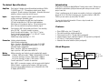
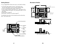
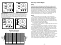
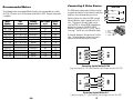
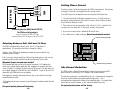
6/15/98
User's Manual
Model 1030
Step Motor Driver
Copyright 1998
Applied Motion Products, Inc.
404 Westridge Drive Watsonville, CA 95076
Tel (408) 761-6555
(800) 525-1609
Fax (408) 761-6544
motors • drives • controls
-15-
Technical Specifications
Introduction
Amplifiers
Thank you for selecting an Applied Motion Products motor control. We hope our
dedication to performance, quality and economy will make your motion control
project successful.
Inputs
Physical
Dual, bipolar H-bridge, pulse width modulated switching at 20kHz.
12-30 VDC input. 0.2 - 1.0 amp/phase output current, factory
configured. 30 watts maximum output power. Automatic idle current
reduction, reduces current after one half second.
Step and direction, optically isolated. Inputs can be wired for
sinking, sourcing or differential signals.
5-12V logic configuration has 680 ohms input impedance
24V logic configuration has 2200 ohms input impedance
Motor steps on rising edge of step line. 10 µsec minimum low
pulse. 50 µsec minimum set up time for direction signal.
Constructed on .062" thick printed circuit board. Two mounting
holes, Ø 0.156". Use plastic standoffs or spacers.
Overall size with vertical headers: 1.6 x 2.25 x 0.77 inches.
Overall size with horizontal headers: 1.6 x 2.55 x 0.77 inches.
See page 13 for detailed drawing.
Ambient temp range (operating): 0 - 70˚C.
Connectors Latching, polarized headers.
Vertical header configuration:
Motor: 5 position. Molex/Waldom part number 22-23-2051.
Input: 6 position. Molex/Waldom part number 22-23-2061.
Horizontal header configuration:
Motor: 5 position. AMP part number 640457-5.
Input: 6 position. AMP part number 640457-6.
Mating
Mating connectors and standoffs are only supplied with samples.
Connectors • Contact: AMP part number 770666-1 (accepts AWG 22-26 wire)
• 5 Position Housing (for motor): AMP number 770602-5
• 6 Position Housing (for inputs): AMP number 770602-6
You will need at least 11 contacts for each drive.
Note: AMP is a connector company, not to be confused with Applied
Motion Products, a motion control company. AMP parts can be
purchased from an AMP distributor such as Allied (800-433-5700)
or Digikey (800-DIGIKEY).
-14-
If there's anything we can do to improve our products or help you use them better,
please call or fax. We'd like to hear from you. Our phone number is (800) 5251609 or you can reach us by fax at (408) 761–6544.
You can also find useful information 24 hours a day at our web site:
www.applied-motion.com.
Features
•
•
•
•
•
•
Drives NEMA motor sizes 14 through 23.
Pulse width modulation switching amplifiers.
Phase current from 0.2 to 1.0 amps (factory configured).
Step and direction inputs, optically isolated, 5-24V logic (factory configured).
Full, half or 1/4 step (factory configured)
Automatic idle current reduction (factory configured)
Block Diagram
Step
Sequencer
step
dir
Optical
Isolation
Idle
Current
Reduction
12-30 VDC
-3-
Amplifier
A+
AB+
B-
to
motor
Getting Started
Mechanical Outline
To use your Applied Motion Products motor control, you will need the following:
• a 12-30 volt DC power supply for the motor. Please read the section
Choosing a Power Supply for help in choosing the right power supply.
• a source of step & direction signals (indexer, oscillator or PLC).
• a source of power to activate the optoisolation circuits. Many indexers & PLCs
have power available for this purpose. If not, you may need a small 5 - 24 VDC
power supply.
• mating connectors (see page 14)
• plastic spacers or stand-offs for mounting (see page 12)
2.00
pin 1
motor connector
0.125
0.70
0.80
1.60
pin 1
logic & power
connector
The sketch below shows where to find the important connection and mounting
points. Please examine it now.
2.25
0.770 MAX
current sensing resistor
with vertical headers
0.062
connector
motor
mounting
hole
(.156")
mounting
hole
(.156")
connector
power
step
direction
current sensing resistor
with horizontal headers
voltage regulator
(Beware, this part gets HOT!!!)
-4-
-13-
.300
Mounting the Drive
Connecting the Power Supply
The 1030 has two .156" holes in the circuit board for mounting. In the design of
this compact, low cost driver, it was necessary to route some circuit boards traces
fairly close to the mounting holes. Therefore, you must only use plastic
standoffs or spacers to support the 1030.
You can drive #4 screws through the top of the board into a plastic spacer, but only
if you put an insulating washer under the screw heads.
An excellent way to mount the 1030 in your application is to use two Richco model
LCBS-TF-6-01 spacers. The LCBS parts can be secured to your application with
#6-32 screws. The 1030 then snaps onto the LCBS spacers, and no metal is in
contact with the 1030. We use that configuration here at Applied Motion.
Richco makes a wide variety of innovative pcb mounting hardware. Their phone
number is 800-621-1892. Internet address is www.richcoplas.com.
If you need information about choosing a power supply, please read Choosing a
Power Supply located in the back of this manual.
If your power supply does not have a fuse on the output or some kind of short
circuit current limiting feature you need to put a 1 amp slow blow fuse between the
drive and power supply. Install the fuse on the positive power supply lead.
Connect the motor power supply positive (+) terminal to pin 2 of the power &
logic connector. Connect power supply return (-) to pin 1. Be careful not to
reverse the wires. Reverse connection will destroy your driver, void your
warranty and generally wreck your day.
Pin 2 (to power supply +)
Pin 1 (to power supply -)
Note: if you are using a motor
with a shielded cable, connect
the drain wire to pin 3.
mounting
hole
(.156")
mounting
hole
(.156")
voltage regulator
(Beware, this part gets HOT!!!)
About the voltage regulator
The 1030 requires 52 mA of power at 5 volts DC internally. We derive this 5V from
the DC power that you provide for the motor. This is a low cost and compact
technique, but does result in some heating of the voltage regulator.
Don't be surprised if the temperature of the regulator reaches 90˚C. This will not
affect the life of your drive, but if you accidentally touch the part, you won't be
happy.
You may add a heat sink to the voltage regulator if you wish. The metal tab is
electrically connected to ground (power supply "-").
Never use your drive in a space where there is no air flow or where the
air temperature is more than 70˚C. Never put the drive where it can
get wet or where metal particles can get on it.
-12-
Pin 5 (motor A+)
Pin 4 (motor A-)
Pin 3 (ground)
Pin 2 (motor B+)
Pin 1 (motor B-)
Connecting the Motor
✔ When connecting the motor, be sure that the power supply is off.
✔ Isolate & secure any unused motor leads.
✔ Never disconnect the motor while the drive is powered up.
✔ Never connect motor leads to ground or to a power supply.
✔ Use a polarized mating connector.
You must now decide how to connect your
motor to the drive.
Four lead motors can only be connected
one way. Please follow the sketch at the
right.
A+
A-
Red
4
lead
motor
Blue
Six lead motors can be connected in
White
Yellow
series or center tap. In series mode,
B+
Bmotors produce more torque at low speeds,
but cannot run as fast as in the center tap
4 Leads
configuration. In series operation, the
motor should be operated at 30% less than the rated current to prevent overheating.
Wiring diagrams for both connection methods are shown on the next page.
-5-
Grn/Wht
ANC
A+
6
lead
motor
White
Green
A+
NC
Red/
Wht
Red
NC = not
connected
B-
Black
NC
Choosing a Power Supply
Grn/Wht
A-
6
lead
motor
White
Green
Red/
Wht
Red
Black
BB+
NC = not
connected
B+
6 Leads Series Connected
NC
6 Leads Center Tap Connected
Eight lead motors can also be connected in two ways: series and parallel. As
with six lead motors, series operation gives you more torque at low speeds and less
torque at high speeds. In series operation, the motor should be operated at 30%
less than the rated current to prevent over heating. The wiring diagrams for eight
lead motors are shown below.
A+
Orange
A+
Blk/Wht
A-
Blk/Wht
8
lead
motor
Org/Wht
Org/
Wht
A-
Black
Red
B+
Red/
Wht
Orange
8
lead
motor
Black
Red
Yellow
Yel/
Wht B-
Yel/
B+ Wht
8 Leads Series Connected
Yel
low
Red/Wht B-
8 Leads Parallel Connected
Step Table (half stepping)
Step 0 is the power up state
DIR=0
ccw
Step
0
1
2
3
4
5
6
7
8
A+
0
+
+
+
0
-
A+
+
0
0
+
+
-6-
B+
0
0
+
+
+
0
B0
+
+
+
0
0
DIR=1
cw
Voltage
Chopper drives work by switching the voltage to the motor terminals on and off
while monitoring current to achieve a precise level of phase current. To do this
efficiently and silently, you’ll want to have a power supply with a voltage rating at
least five times that of the motor. Depending on how fast you want to run the motor,
you may need even more voltage than that. More is better, the only upper limit
being the maximum voltage rating of the drive itself: 30 volts. If you choose an
unregulated power supply, do not exceed 24 volts. This is because unregulated
supplies are rated at full load current. At lesser loads, like when the motor’s not
moving, the actual voltage can be up to 1.4 times the rated voltage.
Current
The maximum supply current you will need is the sum of the two phase
currents. However, you will generally need a lot less than that, depending on the
motor type, voltage, speed and load conditions. That's because the 1030 uses
switching amplifiers, converting a high voltage and low current into lower voltage
and higher current. The more the power supply voltage exceeds the motor voltage,
the less current you’ll need from the power supply.
We recommend the following selection procedure:
1. If you plan to use only a few drives, get a power supply with at least twice the
rated phase current of the motor.
2. If you are designing for mass production and must minimize cost, get one
power supply with more than two times the rated current of the motor . Install the
motor in the application and monitor the current coming out of the power supply
and into the drive at various motor loads. This will tell you how much current you
really need so you can design in a lower cost power supply.
If you plan to use a regulated power supply you may encounter a problem with
current foldback. When you first power up your drive, the full current of both motor
phases will be drawn for a few milliseconds while the stator fields are being
established. After that the amplifiers start chopping and much less current is drawn
from the power supply. If your power supply thinks this initial surge is a short
circuit it may “foldback” to a lower voltage. With many foldback schemes the
voltage returns to normal only after the first motor step and is fine thereafter. In that
sense, unregulated power supplies are better. They are also less expensive.
-11-
Connecting A Pulse Source
The following motors from Applied Motion Products are recommended for use with
the 1030. All motors in the list have been tested with the 1030. Dynamic torque data
is available.
The 1030 inputs contain optical isolation circuitry
to prevent the electrical noise inherent in switching
amplifiers from interfering with your circuits.
Winding
Connection
4 lead
center-end
center-end
center-end
parallel
parallel
parallel
center-end
center-end
parallel
parallel
parallel
Max Torque
oz-in
22
10
17
24
22
34
54
35
56
34
110
140
Current
Amps
1.0
1.0
0.8
0.8
1.0
1.0
1.0
1.0
1.0
1.0
1.0
1.0
A schematic diagram of the input circuit is at the
right. The wiring diagrams below show how to
connect the drive to various pulse sources.
Si-100
STEP+
STEP+
STEP-
STEP-
DIR+
DIR+
DIR-
DIR-
STEP+
STEPDIR+
DIR-
6 - DIR+
5 - DIR4 - STEP+
3 - STEP-
Connecting Applied Motion Si-100
If you are using the Si-100, please purchase the 5V logic version of the 1030
+5V
STEP+
DIR+
STEP
STEP-
DIR
DIR-
1030
Size
inches
1.38 x 1.38 x 1.57
1.65 x 1.65 x 1.34
1.65 x 1.65 x 1.54
1.65 x 1.65 x 1.85
1.65 x 1.65 x 1.30
1.65 x 1.65 x 1.54
1.65 x 1.65 x 1.85
2.22 x 2.22 x 1.5
2.22 x 2.22 x 2.0
2.22 x 2.22 x 1.54
2.22 x 2.22 x 2.13
2.22 x 2.22 x 2.99
SI-1
Motor
Number
5014-842
5017-006
5017-009
5017-013
HT17-068
HT17-072
HT17-076
4023-839
4023-819
HT23-393
HT23-396
HT23-399
Optical isolation also allows the 1030 to accept
step and direction signals ranging from 5 to 24
volts. Furthermore, the input signals can be
sourcing (PNP) or sinking (NPN), depending on
whether you "common" the STEP+ & DIR+
terminals (sinking) or the STEP- & DIR- signals
(sourcing). You can also use differential signals.
inside 1030
1030
Recommended Motors
Connecting Applied Motion Si-1
If you are using the Si-1, please purchase the 5V logic version of the 1030
-10-
-7-
STEP-
Y2
+
DIRSTEP+
DIR+
Setting Phase Current
1030
NAiS FP0 PLC
Y0
+
24VDC
Power
Supply
–
–
Connecting Aromat (NAiS) Model FP0 PLC.
The FP0 has sinking outputs.
If you are using a PLC with 24V logic,
please purchase the 24V logic version of the 1030
The phase current is set at the factory when the 1030 is manufactured. The only way
to change it in the field is to change the current sensing resistors.
If you feel that you must change the motor current, please follow these rules:
1. You must be skilled at soldering to change the resistors. You will void your
warranty by modifying the drive, but at least if you are a skillful solderer, the drive
should still work when you're done.
2. Choose the resistor value according to this formula: R = 0.4 / i, where R is the
sensing resistor you need, and i is the current, in amps, that you want.
3. Use a resistors whose value is between 0.39 and 2.0 ohms.
4. Use 1 watt resistors, metal oxide type. Do not use wirewound resistors.
current sensing resistor
Selecting Between Full, Half and 1/4 Step
The 1030 is configured at the factory for full, half or 1/4 step when it is
manufactured. It is normally not possible to change this setting.
However, if your 1030 was an engineering sample, we may have put the step
sequencer chip in a socket.
If this is the case, and you want to try a different step mode, give a us call - we can
probably provide you with a different sequencing chip to put in the socket.
Why would I prefer one mode over another?
Full step mode will give you the most torque at low speeds. Full stepping also
allows you to achieve higher speeds than half stepping if the speed of your pulse
source is limited. For example, to drive a motor at 25 rev/sec in 1/4 step mode, you
must supply step pulses to the 1030 at a rate of 20,000 Hz. To get 25 rev/sec in full
step mode, only 5,000 pulses/sec are required.
Half stepping is smoother and quieter than full step, so you should use half step
mode whenever posssible.
1/4 stepping provides even more precise positioning and smoother motion than half
stepping.
For special options please call the factory.
-8-
current sensing resistor
Idle Current Reduction
The 1030 includes a feature that automatically reduces the motor current to 60%
when the motor is not moving. This is known as idle current reduction.
The idle current reduction is not adjustable by the user. However we can change the
amount of current reduction during the manufacturing process. This is
accomplished by changing the software in the sequencing chips. On sample drives,
these chips are usually socketed, so units can be retrofitted if necessary.
For special options please call the factory.
-9-