1
MELSEC iQ-R Positioning Module
User's Manual (Application)
-RD75P2
-RD75P4
-RD75D2
-RD75D4
SAFETY PRECAUTIONS
(Read these precautions before using this product.)
Before using this product, please read this manual and the relevant manuals carefully and pay full attention to safety to handle
the product correctly.
The precautions given in this manual are concerned with this product only. For the safety precautions of the programmable
controller system, refer to the MELSEC iQ-R Module Configuration Manual.
In this manual, the safety precautions are classified into two levels: "
WARNING" and "
CAUTION".
WARNING
Indicates that incorrect handling may cause hazardous conditions, resulting in
death or severe injury.
CAUTION
Indicates that incorrect handling may cause hazardous conditions, resulting in
minor or moderate injury or property damage.
Under some circumstances, failure to observe the precautions given under "
CAUTION" may lead to serious
consequences.
Observe the precautions of both levels because they are important for personal and system safety.
Make sure that the end users read this manual and then keep the manual in a safe place for future reference.
[Design Precautions]
WARNING
● Configure safety circuits external to the programmable controller to ensure that the entire system
operates safely even when a fault occurs in the external power supply or the programmable controller.
Failure to do so may result in an accident due to an incorrect output or malfunction.
(1) Emergency stop circuits, protection circuits, and protective interlock circuits for conflicting
operations (such as forward/reverse rotations or upper/lower limit positioning) must be configured
external to the programmable controller.
(2) When the programmable controller detects an abnormal condition, it stops the operation and all
outputs are:
• Turned off if the overcurrent or overvoltage protection of the power supply module is activated.
• Held or turned off according to the parameter setting if the self-diagnostic function of the CPU
module detects an error such as a watchdog timer error.
(3) All outputs may be turned on if an error occurs in a part, such as an I/O control part, where the
CPU module cannot detect any error. To ensure safety operation in such a case, provide a safety
mechanism or a fail-safe circuit external to the programmable controller. For a fail-safe circuit
example, refer to "General Safety Requirements" in the MELSEC iQ-R Module Configuration
Manual.
(4) Outputs may remain on or off due to a failure of a component such as a relay and transistor in an
output circuit. Configure an external circuit for monitoring output signals that could cause a
serious accident.
● In an output circuit, when a load current exceeding the rated current or an overcurrent caused by a
load short-circuit flows for a long time, it may cause smoke and fire. To prevent this, configure an
external safety circuit, such as a fuse.
● Configure a circuit so that the programmable controller is turned on first and then the external power
supply. If the external power supply is turned on first, an accident may occur due to an incorrect output
or malfunction.
● For the operating status of each station after a communication failure, refer to manuals relevant to the
network. Incorrect output or malfunction due to a communication failure may result in an accident.
1
[Design Precautions]
WARNING
● When connecting an external device with a CPU module or intelligent function module to modify data
of a running programmable controller, configure an interlock circuit in the program to ensure that the
entire system will always operate safely. For other forms of control (such as program modification,
parameter change, forced output, or operating status change) of a running programmable controller,
read the relevant manuals carefully and ensure that the operation is safe before proceeding. Improper
operation may damage machines or cause accidents.
● Especially, when a remote programmable controller is controlled by an external device, immediate
action cannot be taken if a problem occurs in the programmable controller due to a communication
failure. To prevent this, configure an interlock circuit in the program, and determine corrective actions
to be taken between the external device and CPU module in case of a communication failure.
● Do not write any data to the "system area" and "write-protect area" of the buffer memory in the
module. Also, do not use any "use prohibited" signals as an output signal from the CPU module to
each module. Doing so may cause malfunction of the programmable controller system. For the
"system area", "write-protect area", and the "use prohibited" signals, refer to the user's manual for the
module used.
● If a communication cable is disconnected, the network may be unstable, resulting in a communication
failure of multiple stations. Configure an interlock circuit in the program to ensure that the entire
system will always operate safely even if communications fail. Failure to do so may result in an
accident due to an incorrect output or malfunction.
● To maintain the safety of the programmable controller system against unauthorized access from
external devices via the network, take appropriate measures. To maintain the safety against
unauthorized access via the Internet, take measures such as installing a firewall.
● Configure safety circuits external to the programmable controller to ensure that the entire system
operates safely even when a fault occurs in the external power supply or the programmable controller.
Failure to do so may result in an accident due to an incorrect output or malfunction.
(1) Machine OPR (Original Point Return) is controlled by two kinds of data: an OPR direction and an
OPR speed. Deceleration starts when the near-point dog signal turns on. If an incorrect OPR
direction is set, motion control may continue without deceleration. To prevent machine damage
caused by this, configure an interlock circuit external to the programmable controller.
(2) When the positioning module detects an error, the motion slows down and stops or the motion
suddenly stops, depending on the stop group setting in parameter. Set the parameters to meet the
specifications of the positioning control system used. In addition, set the OPR parameters and
positioning data within the specified setting range.
(3) Outputs may remain on or off, or become undefined due to a failure of a component such as an
insulation element and transistor in an output circuit, where the positioning module cannot detect
any error. In a system where the incorrect outputs could cause a serious accident, configure an
external circuit for monitoring output signals.
● An absolute position restoration by the positioning module may turn off the servo-on signal (servo off)
for approximately 60ms + scan time, and the motor may run unexpectedly. If this causes a problem,
provide an electromagnetic brake to lock the motor during absolute position restoration.
2
[Design Precautions]
CAUTION
● Do not install the control lines or communication cables together with the main circuit lines or power
cables. Keep a distance of 100mm or more between them. Failure to do so may result in malfunction
due to noise.
● During control of an inductive load such as a lamp, heater, or solenoid valve, a large current
(approximately ten times greater than normal) may flow when the output is turned from off to on.
Therefore, use a module that has a sufficient current rating.
● After the CPU module is powered on or is reset, the time taken to enter the RUN status varies
depending on the system configuration, parameter settings, and/or program size. Design circuits so
that the entire system will always operate safely, regardless of the time.
● Do not power off the programmable controller or reset the CPU module while the settings are being
written. Doing so will make the data in the flash ROM undefined. The values need to be set in the
buffer memory and written to the flash ROM again. Doing so also may cause malfunction or failure of
the module.
● When changing the operating status of the CPU module from external devices (such as the remote
RUN/STOP functions), select "Do Not OPEN in Program" for "Open Method Setting" in the module
parameters. If "OPEN in Program" is selected, an execution of the remote STOP function causes the
communication line to close. Consequently, the CPU module cannot reopen the line, and external
devices cannot execute the remote RUN function.
[Installation Precautions]
WARNING
● Shut off the external power supply (all phases) used in the system before mounting or removing the
module. Failure to do so may result in electric shock or cause the module to fail or malfunction.
3
[Installation Precautions]
CAUTION
● Use the programmable controller in an environment that meets the general specifications in the Safety
Guidelines included with the base unit. Failure to do so may result in electric shock, fire, malfunction,
or damage to or deterioration of the product.
● To mount a module, place the concave part(s) located at the bottom onto the guide(s) of the base unit,
and push in the module until the hook(s) located at the top snaps into place. Incorrect interconnection
may cause malfunction, failure, or drop of the module.
● When using the programmable controller in an environment of frequent vibrations, fix the module with
a screw.
● Tighten the screws within the specified torque range. Undertightening can cause drop of the screw,
short circuit, or malfunction. Overtightening can damage the screw and/or module, resulting in drop,
short circuit, or malfunction.
● When using an extension cable, connect it to the extension cable connector of the base unit securely.
Check the connection for looseness. Poor contact may cause malfunction.
● When using an SD memory card, fully insert it into the SD memory card slot. Check that it is inserted
completely. Poor contact may cause malfunction.
● Securely insert an extended SRAM cassette into the cassette connector of the CPU module. After
insertion, close the cassette cover and check that the cassette is inserted completely. Poor contact
may cause malfunction.
● Do not directly touch any conductive parts and electronic components of the module, SD memory
card, extended SRAM cassette, or connector. Doing so can cause malfunction or failure of the
module.
[Wiring Precautions]
WARNING
● Shut off the external power supply (all phases) used in the system before installation and wiring.
Failure to do so may result in electric shock or cause the module to fail or malfunction.
● After installation and wiring, attach the included terminal cover to the module before turning it on for
operation. Failure to do so may result in electric shock.
4
[Wiring Precautions]
CAUTION
● Individually ground the FG and LG terminals of the programmable controller with a ground resistance
of 100 ohms or less. Failure to do so may result in electric shock or malfunction.
● Use applicable solderless terminals and tighten them within the specified torque range. If any spade
solderless terminal is used, it may be disconnected when the terminal screw comes loose, resulting in
failure.
● Check the rated voltage and signal layout before wiring to the module, and connect the cables
correctly. Connecting a power supply with a different voltage rating or incorrect wiring may cause fire
or failure.
● Connectors for external devices must be crimped or pressed with the tool specified by the
manufacturer, or must be correctly soldered. Incomplete connections may cause short circuit, fire, or
malfunction.
● Securely connect the connector to the module. Poor contact may cause malfunction.
● Do not install the control lines or communication cables together with the main circuit lines or power
cables. Keep a distance of 100mm or more between them. Failure to do so may result in malfunction
due to noise.
● Place the cables in a duct or clamp them. If not, dangling cable may swing or inadvertently be pulled,
resulting in damage to the module or cables or malfunction due to poor contact. Do not clamp the
extension cables with the jacket stripped.
● Check the interface type and correctly connect the cable. Incorrect wiring (connecting the cable to an
incorrect interface) may cause failure of the module and external device.
● Tighten the terminal screws or connector screws within the specified torque range. Undertightening
can cause drop of the screw, short circuit, fire, or malfunction. Overtightening can damage the screw
and/or module, resulting in drop, short circuit, fire, or malfunction.
● When disconnecting the cable from the module, do not pull the cable by the cable part. For the cable
with connector, hold the connector part of the cable. For the cable connected to the terminal block,
loosen the terminal screw. Pulling the cable connected to the module may result in malfunction or
damage to the module or cable.
● Prevent foreign matter such as dust or wire chips from entering the module. Such foreign matter can
cause a fire, failure, or malfunction.
● A protective film is attached to the top of the module to prevent foreign matter, such as wire chips,
from entering the module during wiring. Do not remove the film during wiring. Remove it for heat
dissipation before system operation.
● Programmable controllers must be installed in control panels. Connect the main power supply to the
power supply module in the control panel through a relay terminal block. Wiring and replacement of a
power supply module must be performed by qualified maintenance personnel with knowledge of
protection against electric shock. For wiring, refer to the MELSEC iQ-R Module Configuration Manual.
● For Ethernet cables to be used in the system, select the ones that meet the specifications in the user's
manual for the module used. If not, normal data transmission is not guaranteed.
5
[Startup and Maintenance Precautions]
WARNING
● Do not touch any terminal while power is on. Doing so will cause electric shock or malfunction.
● Correctly connect the battery connector. Do not charge, disassemble, heat, short-circuit, solder, or
throw the battery into the fire. Also, do not expose it to liquid or strong shock. Doing so will cause the
battery to produce heat, explode, ignite, or leak, resulting in injury and fire.
● Shut off the external power supply (all phases) used in the system before cleaning the module or
retightening the terminal screws, connector screws, or module fixing screws. Failure to do so may
result in electric shock.
6
[Startup and Maintenance Precautions]
CAUTION
● When connecting an external device with a CPU module or intelligent function module to modify data
of a running programmable controller, configure an interlock circuit in the program to ensure that the
entire system will always operate safely. For other forms of control (such as program modification,
parameter change, forced output, or operating status change) of a running programmable controller,
read the relevant manuals carefully and ensure that the operation is safe before proceeding. Improper
operation may damage machines or cause accidents.
● Especially, when a remote programmable controller is controlled by an external device, immediate
action cannot be taken if a problem occurs in the programmable controller due to a communication
failure. To prevent this, configure an interlock circuit in the program, and determine corrective actions
to be taken between the external device and CPU module in case of a communication failure.
● Do not disassemble or modify the modules. Doing so may cause failure, malfunction, injury, or a fire.
● Use any radio communication device such as a cellular phone or PHS (Personal Handy-phone
System) more than 25cm away in all directions from the programmable controller. Failure to do so
may cause malfunction.
● Shut off the external power supply (all phases) used in the system before mounting or removing the
module. Failure to do so may cause the module to fail or malfunction.
● Tighten the screws within the specified torque range. Undertightening can cause drop of the
component or wire, short circuit, or malfunction. Overtightening can damage the screw and/or module,
resulting in drop, short circuit, or malfunction.
● After the first use of the product, do not mount/remove the module to/from the base unit, and the
terminal block to/from the module, and do not insert/remove the extended SRAM cassette to/from the
CPU module more than 50 times (IEC 61131-2 compliant) respectively. Exceeding the limit may cause
malfunction.
● After the first use of the product, do not insert/remove the SD memory card to/from the CPU module
more than 500 times. Exceeding the limit may cause malfunction.
● Do not touch the metal terminals on the back side of the SD memory card. Doing so may cause
malfunction or failure.
● Do not touch the integrated circuits on the circuit board of an extended SRAM cassette. Doing so may
cause malfunction or failure of the module.
● Do not drop or apply shock to the battery to be installed in the module. Doing so may damage the
battery, causing the battery fluid to leak inside the battery. If the battery is dropped or any shock is
applied to it, dispose of it without using.
● Startup and maintenance of a control panel must be performed by qualified maintenance personnel
with knowledge of protection against electric shock. Lock the control panel so that only qualified
maintenance personnel can operate it.
● Before handling the module, touch a conducting object such as a grounded metal to discharge the
static electricity from the human body. Failure to do so may cause the module to fail or malfunction.
● Before testing the operation, set a low speed value for the speed limit parameter so that the operation
can be stopped immediately upon occurrence of a hazardous condition.
● Confirm and adjust the program and each parameter before operation. Unpredictable movements
may occur depending on the machine.
7
[Operating Precautions]
CAUTION
● When changing data and operating status, and modifying program of the running programmable
controller from an external device such as a personal computer connected to an intelligent function
module, read relevant manuals carefully and ensure the safety before operation. Incorrect change or
modification may cause system malfunction, damage to the machines, or accidents.
● Do not power off the programmable controller or reset the CPU module while the setting values in the
buffer memory are being written to the flash ROM in the module. Doing so will make the data in the
flash ROM undefined. The values need to be set in the buffer memory and written to the flash ROM
again. Doing so can cause malfunction or failure of the module.
● Note that when the reference axis speed is specified for interpolation operation, the speed of the
partner axis (2nd, 3rd, or 4th axis) may exceed the speed limit value.
● Do not go near the machine during test operations or during operations such as teaching. Doing so
may lead to injuries.
[Disposal Precautions]
CAUTION
● When disposing of this product, treat it as industrial waste.
● When disposing of batteries, separate them from other wastes according to the local regulations. For
details on battery regulations in EU member states, refer to the MELSEC iQ-R Module Configuration
Manual.
[Transportation Precautions]
CAUTION
● When transporting lithium batteries, follow the transportation regulations. For details on the regulated
models, refer to the MELSEC iQ-R Module Configuration Manual.
● The halogens (such as fluorine, chlorine, bromine, and iodine), which are contained in a fumigant
used for disinfection and pest control of wood packaging materials, may cause failure of the product.
Prevent the entry of fumigant residues into the product or consider other methods (such as heat
treatment) instead of fumigation. The disinfection and pest control measures must be applied to
unprocessed raw wood.
8
CONDITIONS OF USE FOR THE PRODUCT
(1) Mitsubishi programmable controller ("the PRODUCT") shall be used in conditions;
i) where any problem, fault or failure occurring in the PRODUCT, if any, shall not lead to any major or serious accident;
and
ii) where the backup and fail-safe function are systematically or automatically provided outside of the PRODUCT for the
case of any problem, fault or failure occurring in the PRODUCT.
(2) The PRODUCT has been designed and manufactured for the purpose of being used in general industries.
MITSUBISHI SHALL HAVE NO RESPONSIBILITY OR LIABILITY (INCLUDING, BUT NOT LIMITED TO ANY AND ALL
RESPONSIBILITY OR LIABILITY BASED ON CONTRACT, WARRANTY, TORT, PRODUCT LIABILITY) FOR ANY
INJURY OR DEATH TO PERSONS OR LOSS OR DAMAGE TO PROPERTY CAUSED BY the PRODUCT THAT ARE
OPERATED OR USED IN APPLICATION NOT INTENDED OR EXCLUDED BY INSTRUCTIONS, PRECAUTIONS, OR
WARNING CONTAINED IN MITSUBISHI'S USER, INSTRUCTION AND/OR SAFETY MANUALS, TECHNICAL
BULLETINS AND GUIDELINES FOR the PRODUCT.
("Prohibited Application")
Prohibited Applications include, but not limited to, the use of the PRODUCT in;
• Nuclear Power Plants and any other power plants operated by Power companies, and/or any other cases in which the
public could be affected if any problem or fault occurs in the PRODUCT.
• Railway companies or Public service purposes, and/or any other cases in which establishment of a special quality
assurance system is required by the Purchaser or End User.
• Aircraft or Aerospace, Medical applications, Train equipment, transport equipment such as Elevator and Escalator,
Incineration and Fuel devices, Vehicles, Manned transportation, Equipment for Recreation and Amusement, and
Safety devices, handling of Nuclear or Hazardous Materials or Chemicals, Mining and Drilling, and/or other
applications where there is a significant risk of injury to the public or property.
Notwithstanding the above, restrictions Mitsubishi may in its sole discretion, authorize use of the PRODUCT in one or
more of the Prohibited Applications, provided that the usage of the PRODUCT is limited only for the specific
applications agreed to by Mitsubishi and provided further that no special quality assurance or fail-safe, redundant or
other safety features which exceed the general specifications of the PRODUCTs are required. For details, please
contact the Mitsubishi representative in your region.
INTRODUCTION
Thank you for purchasing the Mitsubishi MELSEC iQ-R series programmable controllers.
This manual describes the functions, programming, and troubleshooting of the relevant products listed below.
Before using this product, please read this manual and the relevant manuals carefully and develop familiarity with the
functions and performance of the MELSEC iQ-R series programmable controller to handle the product correctly.
When applying the program examples provided in this manual to an actual system, ensure the applicability and confirm that it
will not cause system control problems.
Please make sure that the end users read this manual.
9
Relevant products
RD75P2, RD75P4, RD75D2, RD75D4
In this manual, buffer memory areas are classified into four groups using the following symbols. Each area
name is common to axis 1 to 4.
• [Pr.**]: Positioning parameter and OPR parameter
• [Da.**]: Positioning data and block start data
• [Md.**]: Monitor data
• [Cd.**]: Control data
Unless otherwise specified, this manual describes dedicated instructions using G(P).**** instructions. When
using Z(P).**** instructions, regard G(P).**** as Z(P).****. Applicable devices differ between G(P).****
instructions and Z(P).**** instructions. Check the devices in the following manual.
MELSEC iQ-R Programming Manual (Instructions, Standard Functions/Function Blocks)
10
MEMO
11
CONTENTS
SAFETY PRECAUTIONS . . . . . . . . . . . . . . . . . . . . . . . . . . . . . . . . . . . . . . . . . . . . . . . . . . . . . . . . . . . . . . . . . . . .1
CONDITIONS OF USE FOR THE PRODUCT . . . . . . . . . . . . . . . . . . . . . . . . . . . . . . . . . . . . . . . . . . . . . . . . . . . .9
INTRODUCTION . . . . . . . . . . . . . . . . . . . . . . . . . . . . . . . . . . . . . . . . . . . . . . . . . . . . . . . . . . . . . . . . . . . . . . . . . . .9
RELEVANT MANUALS . . . . . . . . . . . . . . . . . . . . . . . . . . . . . . . . . . . . . . . . . . . . . . . . . . . . . . . . . . . . . . . . . . . . .17
TERMS . . . . . . . . . . . . . . . . . . . . . . . . . . . . . . . . . . . . . . . . . . . . . . . . . . . . . . . . . . . . . . . . . . . . . . . . . . . . . . . . .17
CHAPTER 1
1.1
STARTING AND STOPPING
18
Starting . . . . . . . . . . . . . . . . . . . . . . . . . . . . . . . . . . . . . . . . . . . . . . . . . . . . . . . . . . . . . . . . . . . . . . . . . . . . . . . . 18
Normal start . . . . . . . . . . . . . . . . . . . . . . . . . . . . . . . . . . . . . . . . . . . . . . . . . . . . . . . . . . . . . . . . . . . . . . . . . . . . . 21
Quick start . . . . . . . . . . . . . . . . . . . . . . . . . . . . . . . . . . . . . . . . . . . . . . . . . . . . . . . . . . . . . . . . . . . . . . . . . . . . . . 23
Multiple axes simultaneous start . . . . . . . . . . . . . . . . . . . . . . . . . . . . . . . . . . . . . . . . . . . . . . . . . . . . . . . . . . . . . 28
1.2
Stopping . . . . . . . . . . . . . . . . . . . . . . . . . . . . . . . . . . . . . . . . . . . . . . . . . . . . . . . . . . . . . . . . . . . . . . . . . . . . . . . 31
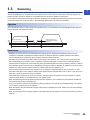
1.3
Restarting. . . . . . . . . . . . . . . . . . . . . . . . . . . . . . . . . . . . . . . . . . . . . . . . . . . . . . . . . . . . . . . . . . . . . . . . . . . . . . 35
CHAPTER 2
OPR CONTROL
37
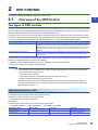
2.1
Overview of the OPR Control . . . . . . . . . . . . . . . . . . . . . . . . . . . . . . . . . . . . . . . . . . . . . . . . . . . . . . . . . . . . . . 37
2.2
Machine OPR . . . . . . . . . . . . . . . . . . . . . . . . . . . . . . . . . . . . . . . . . . . . . . . . . . . . . . . . . . . . . . . . . . . . . . . . . . . 39
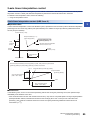
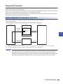
Two types of OPR controls . . . . . . . . . . . . . . . . . . . . . . . . . . . . . . . . . . . . . . . . . . . . . . . . . . . . . . . . . . . . . . . . . 37
Operation overview of the machine OPR . . . . . . . . . . . . . . . . . . . . . . . . . . . . . . . . . . . . . . . . . . . . . . . . . . . . . . 39
Machine OPR method . . . . . . . . . . . . . . . . . . . . . . . . . . . . . . . . . . . . . . . . . . . . . . . . . . . . . . . . . . . . . . . . . . . . . 40
Near-point dog method . . . . . . . . . . . . . . . . . . . . . . . . . . . . . . . . . . . . . . . . . . . . . . . . . . . . . . . . . . . . . . . . . . . . 41
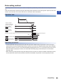
Stopper method 1 . . . . . . . . . . . . . . . . . . . . . . . . . . . . . . . . . . . . . . . . . . . . . . . . . . . . . . . . . . . . . . . . . . . . . . . . 43
Stopper method 2 . . . . . . . . . . . . . . . . . . . . . . . . . . . . . . . . . . . . . . . . . . . . . . . . . . . . . . . . . . . . . . . . . . . . . . . . 46
Stopper method 3 . . . . . . . . . . . . . . . . . . . . . . . . . . . . . . . . . . . . . . . . . . . . . . . . . . . . . . . . . . . . . . . . . . . . . . . . 49
Count method 1 . . . . . . . . . . . . . . . . . . . . . . . . . . . . . . . . . . . . . . . . . . . . . . . . . . . . . . . . . . . . . . . . . . . . . . . . . . 51
Count method 2 . . . . . . . . . . . . . . . . . . . . . . . . . . . . . . . . . . . . . . . . . . . . . . . . . . . . . . . . . . . . . . . . . . . . . . . . . . 53
Data setting method . . . . . . . . . . . . . . . . . . . . . . . . . . . . . . . . . . . . . . . . . . . . . . . . . . . . . . . . . . . . . . . . . . . . . . 55
2.3
Fast OPR . . . . . . . . . . . . . . . . . . . . . . . . . . . . . . . . . . . . . . . . . . . . . . . . . . . . . . . . . . . . . . . . . . . . . . . . . . . . . . 56
Operation overview of the fast OPR . . . . . . . . . . . . . . . . . . . . . . . . . . . . . . . . . . . . . . . . . . . . . . . . . . . . . . . . . . 56
CHAPTER 3
3.1
MAJOR POSITIONING CONTROL
58
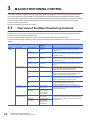
Overview of the Major Positioning Controls. . . . . . . . . . . . . . . . . . . . . . . . . . . . . . . . . . . . . . . . . . . . . . . . . . 58
Data required for major positioning control . . . . . . . . . . . . . . . . . . . . . . . . . . . . . . . . . . . . . . . . . . . . . . . . . . . . . 60
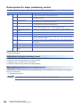
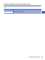
Operation pattern of major positioning control. . . . . . . . . . . . . . . . . . . . . . . . . . . . . . . . . . . . . . . . . . . . . . . . . . . 61
Specifying the positioning address . . . . . . . . . . . . . . . . . . . . . . . . . . . . . . . . . . . . . . . . . . . . . . . . . . . . . . . . . . . 70
Checking the current value . . . . . . . . . . . . . . . . . . . . . . . . . . . . . . . . . . . . . . . . . . . . . . . . . . . . . . . . . . . . . . . . . 71
Handling degree (control unit) . . . . . . . . . . . . . . . . . . . . . . . . . . . . . . . . . . . . . . . . . . . . . . . . . . . . . . . . . . . . . . . 73
Interpolation control . . . . . . . . . . . . . . . . . . . . . . . . . . . . . . . . . . . . . . . . . . . . . . . . . . . . . . . . . . . . . . . . . . . . . . . 76
3.2
Positioning Data Setting . . . . . . . . . . . . . . . . . . . . . . . . . . . . . . . . . . . . . . . . . . . . . . . . . . . . . . . . . . . . . . . . . . 81
Relation between each control and positioning data . . . . . . . . . . . . . . . . . . . . . . . . . . . . . . . . . . . . . . . . . . . . . . 81
1-axis linear control . . . . . . . . . . . . . . . . . . . . . . . . . . . . . . . . . . . . . . . . . . . . . . . . . . . . . . . . . . . . . . . . . . . . . . . 83
2-axis linear interpolation control. . . . . . . . . . . . . . . . . . . . . . . . . . . . . . . . . . . . . . . . . . . . . . . . . . . . . . . . . . . . . 85
3-axis linear interpolation control. . . . . . . . . . . . . . . . . . . . . . . . . . . . . . . . . . . . . . . . . . . . . . . . . . . . . . . . . . . . . 89
4-axis linear interpolation control. . . . . . . . . . . . . . . . . . . . . . . . . . . . . . . . . . . . . . . . . . . . . . . . . . . . . . . . . . . . . 93
Fixed-feed control . . . . . . . . . . . . . . . . . . . . . . . . . . . . . . . . . . . . . . . . . . . . . . . . . . . . . . . . . . . . . . . . . . . . . . . . 95
2-axis circular interpolation control with the sub point specified . . . . . . . . . . . . . . . . . . . . . . . . . . . . . . . . . . . . . 98
2-axis circular interpolation control with the center point specified . . . . . . . . . . . . . . . . . . . . . . . . . . . . . . . . . . 102
3-axis helical interpolation control with sub point specified . . . . . . . . . . . . . . . . . . . . . . . . . . . . . . . . . . . . . . . . 108
12
3-axis helical interpolation control with center point specified . . . . . . . . . . . . . . . . . . . . . . . . . . . . . . . . . . . . . . 114
Speed control . . . . . . . . . . . . . . . . . . . . . . . . . . . . . . . . . . . . . . . . . . . . . . . . . . . . . . . . . . . . . . . . . . . . . . . . . . 121
Speed-position switching control (INC mode) . . . . . . . . . . . . . . . . . . . . . . . . . . . . . . . . . . . . . . . . . . . . . . . . . . 124
Speed-position switching control (ABS mode). . . . . . . . . . . . . . . . . . . . . . . . . . . . . . . . . . . . . . . . . . . . . . . . . . 131
Position-speed switching control . . . . . . . . . . . . . . . . . . . . . . . . . . . . . . . . . . . . . . . . . . . . . . . . . . . . . . . . . . . . 138
Current value change . . . . . . . . . . . . . . . . . . . . . . . . . . . . . . . . . . . . . . . . . . . . . . . . . . . . . . . . . . . . . . . . . . . . 144
NOP instruction . . . . . . . . . . . . . . . . . . . . . . . . . . . . . . . . . . . . . . . . . . . . . . . . . . . . . . . . . . . . . . . . . . . . . . . . . 148
JUMP instruction . . . . . . . . . . . . . . . . . . . . . . . . . . . . . . . . . . . . . . . . . . . . . . . . . . . . . . . . . . . . . . . . . . . . . . . . 149
LEND . . . . . . . . . . . . . . . . . . . . . . . . . . . . . . . . . . . . . . . . . . . . . . . . . . . . . . . . . . . . . . . . . . . . . . . . . . . . . . . . . 152
CHAPTER 4
4.1
ADVANCED POSITIONING CONTROL
153
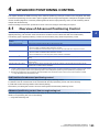
Overview of Advanced Positioning Control . . . . . . . . . . . . . . . . . . . . . . . . . . . . . . . . . . . . . . . . . . . . . . . . . 153
Data required for advanced positioning control . . . . . . . . . . . . . . . . . . . . . . . . . . . . . . . . . . . . . . . . . . . . . . . . . 154
Block start data and Condition data configurations . . . . . . . . . . . . . . . . . . . . . . . . . . . . . . . . . . . . . . . . . . . . . . 155
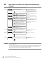
4.2
Execution Procedure for Advanced Positioning Control . . . . . . . . . . . . . . . . . . . . . . . . . . . . . . . . . . . . . . 156
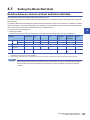
4.3
Setting the Block Start Data . . . . . . . . . . . . . . . . . . . . . . . . . . . . . . . . . . . . . . . . . . . . . . . . . . . . . . . . . . . . . . 157
CONTENTS
LOOP. . . . . . . . . . . . . . . . . . . . . . . . . . . . . . . . . . . . . . . . . . . . . . . . . . . . . . . . . . . . . . . . . . . . . . . . . . . . . . . . . 151
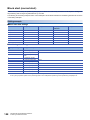
Relation between various controls and block start data . . . . . . . . . . . . . . . . . . . . . . . . . . . . . . . . . . . . . . . . . . 157
Block start (normal start) . . . . . . . . . . . . . . . . . . . . . . . . . . . . . . . . . . . . . . . . . . . . . . . . . . . . . . . . . . . . . . . . . . 158
Condition start . . . . . . . . . . . . . . . . . . . . . . . . . . . . . . . . . . . . . . . . . . . . . . . . . . . . . . . . . . . . . . . . . . . . . . . . . . 160
Wait start . . . . . . . . . . . . . . . . . . . . . . . . . . . . . . . . . . . . . . . . . . . . . . . . . . . . . . . . . . . . . . . . . . . . . . . . . . . . . . 161
Simultaneous start. . . . . . . . . . . . . . . . . . . . . . . . . . . . . . . . . . . . . . . . . . . . . . . . . . . . . . . . . . . . . . . . . . . . . . . 162
Repeated start (FOR loop) . . . . . . . . . . . . . . . . . . . . . . . . . . . . . . . . . . . . . . . . . . . . . . . . . . . . . . . . . . . . . . . . 163
Repeated start (FOR condition). . . . . . . . . . . . . . . . . . . . . . . . . . . . . . . . . . . . . . . . . . . . . . . . . . . . . . . . . . . . . 164
Restrictions when the NEXT start is used . . . . . . . . . . . . . . . . . . . . . . . . . . . . . . . . . . . . . . . . . . . . . . . . . . . . . 165
4.4
Setting the Condition Data . . . . . . . . . . . . . . . . . . . . . . . . . . . . . . . . . . . . . . . . . . . . . . . . . . . . . . . . . . . . . . . 166
Relation between various controls and condition data . . . . . . . . . . . . . . . . . . . . . . . . . . . . . . . . . . . . . . . . . . . 166
Setting examples of the condition data . . . . . . . . . . . . . . . . . . . . . . . . . . . . . . . . . . . . . . . . . . . . . . . . . . . . . . . 168
4.5
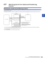
Start Program for the Advanced Positioning Control . . . . . . . . . . . . . . . . . . . . . . . . . . . . . . . . . . . . . . . . . 169
Starting the advanced positioning control . . . . . . . . . . . . . . . . . . . . . . . . . . . . . . . . . . . . . . . . . . . . . . . . . . . . . 169
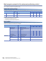
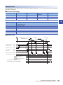
Start program example for the advanced positioning control . . . . . . . . . . . . . . . . . . . . . . . . . . . . . . . . . . . . . . 170
CHAPTER 5
5.1
MANUAL CONTROL
173
Overview of the Manual Control. . . . . . . . . . . . . . . . . . . . . . . . . . . . . . . . . . . . . . . . . . . . . . . . . . . . . . . . . . . 173
Three manual control methods . . . . . . . . . . . . . . . . . . . . . . . . . . . . . . . . . . . . . . . . . . . . . . . . . . . . . . . . . . . . . 173
5.2
JOG Operation . . . . . . . . . . . . . . . . . . . . . . . . . . . . . . . . . . . . . . . . . . . . . . . . . . . . . . . . . . . . . . . . . . . . . . . . . 175
Overview of the JOG operation . . . . . . . . . . . . . . . . . . . . . . . . . . . . . . . . . . . . . . . . . . . . . . . . . . . . . . . . . . . . . 175
Operation procedure of the JOG operation . . . . . . . . . . . . . . . . . . . . . . . . . . . . . . . . . . . . . . . . . . . . . . . . . . . . 177
Parameters required for the JOG operation . . . . . . . . . . . . . . . . . . . . . . . . . . . . . . . . . . . . . . . . . . . . . . . . . . . 178
Creating a start program for the JOG operation . . . . . . . . . . . . . . . . . . . . . . . . . . . . . . . . . . . . . . . . . . . . . . . . 179
Operation example of the JOG operation . . . . . . . . . . . . . . . . . . . . . . . . . . . . . . . . . . . . . . . . . . . . . . . . . . . . . 181
5.3
Inching Operation . . . . . . . . . . . . . . . . . . . . . . . . . . . . . . . . . . . . . . . . . . . . . . . . . . . . . . . . . . . . . . . . . . . . . . 184
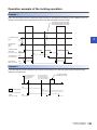
Operation overview of the inching operation . . . . . . . . . . . . . . . . . . . . . . . . . . . . . . . . . . . . . . . . . . . . . . . . . . . 184
Operation procedure of the inching operation . . . . . . . . . . . . . . . . . . . . . . . . . . . . . . . . . . . . . . . . . . . . . . . . . . 187
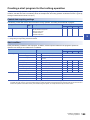
Parameters required for the inching operation . . . . . . . . . . . . . . . . . . . . . . . . . . . . . . . . . . . . . . . . . . . . . . . . . 188
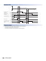
Creating a start program for the inching operation . . . . . . . . . . . . . . . . . . . . . . . . . . . . . . . . . . . . . . . . . . . . . . 189
Operation example of the inching operation . . . . . . . . . . . . . . . . . . . . . . . . . . . . . . . . . . . . . . . . . . . . . . . . . . . 191
5.4
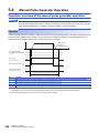
Manual Pulse Generator Operation . . . . . . . . . . . . . . . . . . . . . . . . . . . . . . . . . . . . . . . . . . . . . . . . . . . . . . . . 192
Operation overview of the manual pulse generator operation. . . . . . . . . . . . . . . . . . . . . . . . . . . . . . . . . . . . . . 192
Operation procedure of the manual pulse generator operation. . . . . . . . . . . . . . . . . . . . . . . . . . . . . . . . . . . . . 196
13
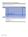
Parameters required for the manual pulse generator operation . . . . . . . . . . . . . . . . . . . . . . . . . . . . . . . . . . . . 197
Creating a program to enable or disable the manual pulse generator operation . . . . . . . . . . . . . . . . . . . . . . . 198
CHAPTER 6
INTER-MODULE SYNCHRONIZATION FUNCTION
(SIMULTANEOUS START OF MULTIPLE MODULES)
200
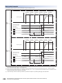
6.1
Control in Pre-analysis Mode . . . . . . . . . . . . . . . . . . . . . . . . . . . . . . . . . . . . . . . . . . . . . . . . . . . . . . . . . . . . . 201
6.2
Control in Normal Analysis Mode . . . . . . . . . . . . . . . . . . . . . . . . . . . . . . . . . . . . . . . . . . . . . . . . . . . . . . . . . 205
CHAPTER 7
7.1
CONTROL SUB FUNCTIONS
208
Overview of Sub Functions . . . . . . . . . . . . . . . . . . . . . . . . . . . . . . . . . . . . . . . . . . . . . . . . . . . . . . . . . . . . . . 208
Overview of sub functions . . . . . . . . . . . . . . . . . . . . . . . . . . . . . . . . . . . . . . . . . . . . . . . . . . . . . . . . . . . . . . . . . 208
7.2
Sub Functions Specific to Machine OPR . . . . . . . . . . . . . . . . . . . . . . . . . . . . . . . . . . . . . . . . . . . . . . . . . . . 210
OPR retry function . . . . . . . . . . . . . . . . . . . . . . . . . . . . . . . . . . . . . . . . . . . . . . . . . . . . . . . . . . . . . . . . . . . . . . . 210
OP shift function . . . . . . . . . . . . . . . . . . . . . . . . . . . . . . . . . . . . . . . . . . . . . . . . . . . . . . . . . . . . . . . . . . . . . . . . 214
7.3
Function to Compensate Control. . . . . . . . . . . . . . . . . . . . . . . . . . . . . . . . . . . . . . . . . . . . . . . . . . . . . . . . . . 217
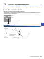
Backlash compensation function . . . . . . . . . . . . . . . . . . . . . . . . . . . . . . . . . . . . . . . . . . . . . . . . . . . . . . . . . . . . 217
Electronic gear function . . . . . . . . . . . . . . . . . . . . . . . . . . . . . . . . . . . . . . . . . . . . . . . . . . . . . . . . . . . . . . . . . . . 219
Near pass function. . . . . . . . . . . . . . . . . . . . . . . . . . . . . . . . . . . . . . . . . . . . . . . . . . . . . . . . . . . . . . . . . . . . . . . 225
Output timing selection of near pass control . . . . . . . . . . . . . . . . . . . . . . . . . . . . . . . . . . . . . . . . . . . . . . . . . . . 227
7.4
Function to Limit Control . . . . . . . . . . . . . . . . . . . . . . . . . . . . . . . . . . . . . . . . . . . . . . . . . . . . . . . . . . . . . . . . 229
Speed limit function . . . . . . . . . . . . . . . . . . . . . . . . . . . . . . . . . . . . . . . . . . . . . . . . . . . . . . . . . . . . . . . . . . . . . . 229
Torque limit function. . . . . . . . . . . . . . . . . . . . . . . . . . . . . . . . . . . . . . . . . . . . . . . . . . . . . . . . . . . . . . . . . . . . . . 231
Software stroke limit function. . . . . . . . . . . . . . . . . . . . . . . . . . . . . . . . . . . . . . . . . . . . . . . . . . . . . . . . . . . . . . . 234
Hardware stroke limit function . . . . . . . . . . . . . . . . . . . . . . . . . . . . . . . . . . . . . . . . . . . . . . . . . . . . . . . . . . . . . . 240
7.5
Functions that Change Control Details . . . . . . . . . . . . . . . . . . . . . . . . . . . . . . . . . . . . . . . . . . . . . . . . . . . . . 242
Speed change function . . . . . . . . . . . . . . . . . . . . . . . . . . . . . . . . . . . . . . . . . . . . . . . . . . . . . . . . . . . . . . . . . . . 242
Override function . . . . . . . . . . . . . . . . . . . . . . . . . . . . . . . . . . . . . . . . . . . . . . . . . . . . . . . . . . . . . . . . . . . . . . . . 247
Acceleration/deceleration time change function . . . . . . . . . . . . . . . . . . . . . . . . . . . . . . . . . . . . . . . . . . . . . . . . 250
Torque change function . . . . . . . . . . . . . . . . . . . . . . . . . . . . . . . . . . . . . . . . . . . . . . . . . . . . . . . . . . . . . . . . . . . 253
Target position change function. . . . . . . . . . . . . . . . . . . . . . . . . . . . . . . . . . . . . . . . . . . . . . . . . . . . . . . . . . . . . 255
7.6
Function Related to Start . . . . . . . . . . . . . . . . . . . . . . . . . . . . . . . . . . . . . . . . . . . . . . . . . . . . . . . . . . . . . . . . 258
Pre-reading start function . . . . . . . . . . . . . . . . . . . . . . . . . . . . . . . . . . . . . . . . . . . . . . . . . . . . . . . . . . . . . . . . . 258
Start time adjustment function . . . . . . . . . . . . . . . . . . . . . . . . . . . . . . . . . . . . . . . . . . . . . . . . . . . . . . . . . . . . . . 261
7.7
Absolute Position Restoration Function. . . . . . . . . . . . . . . . . . . . . . . . . . . . . . . . . . . . . . . . . . . . . . . . . . . . 263
Configuration and preparation of the absolute position detection system . . . . . . . . . . . . . . . . . . . . . . . . . . . . . 263
Overview of the absolute position detection system . . . . . . . . . . . . . . . . . . . . . . . . . . . . . . . . . . . . . . . . . . . . . 264
Transmission procedure for absolute position signal . . . . . . . . . . . . . . . . . . . . . . . . . . . . . . . . . . . . . . . . . . . . 264
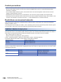
Control precautions . . . . . . . . . . . . . . . . . . . . . . . . . . . . . . . . . . . . . . . . . . . . . . . . . . . . . . . . . . . . . . . . . . . . . . 266
Restrictions on movement amounts . . . . . . . . . . . . . . . . . . . . . . . . . . . . . . . . . . . . . . . . . . . . . . . . . . . . . . . . . 266
7.8
Function Related to Stop . . . . . . . . . . . . . . . . . . . . . . . . . . . . . . . . . . . . . . . . . . . . . . . . . . . . . . . . . . . . . . . . 268
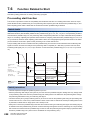
Stop command processing for deceleration stop function . . . . . . . . . . . . . . . . . . . . . . . . . . . . . . . . . . . . . . . . . 268
Continuous operation interrupt function. . . . . . . . . . . . . . . . . . . . . . . . . . . . . . . . . . . . . . . . . . . . . . . . . . . . . . . 270
Step function . . . . . . . . . . . . . . . . . . . . . . . . . . . . . . . . . . . . . . . . . . . . . . . . . . . . . . . . . . . . . . . . . . . . . . . . . . . 272
7.9
Other Functions. . . . . . . . . . . . . . . . . . . . . . . . . . . . . . . . . . . . . . . . . . . . . . . . . . . . . . . . . . . . . . . . . . . . . . . . 276
Skip function . . . . . . . . . . . . . . . . . . . . . . . . . . . . . . . . . . . . . . . . . . . . . . . . . . . . . . . . . . . . . . . . . . . . . . . . . . . 276
M code output function . . . . . . . . . . . . . . . . . . . . . . . . . . . . . . . . . . . . . . . . . . . . . . . . . . . . . . . . . . . . . . . . . . . 279
Teaching function. . . . . . . . . . . . . . . . . . . . . . . . . . . . . . . . . . . . . . . . . . . . . . . . . . . . . . . . . . . . . . . . . . . . . . . . 283
Command in-position function . . . . . . . . . . . . . . . . . . . . . . . . . . . . . . . . . . . . . . . . . . . . . . . . . . . . . . . . . . . . . . 288
Acceleration/deceleration processing function . . . . . . . . . . . . . . . . . . . . . . . . . . . . . . . . . . . . . . . . . . . . . . . . . 290
Deceleration start flag function . . . . . . . . . . . . . . . . . . . . . . . . . . . . . . . . . . . . . . . . . . . . . . . . . . . . . . . . . . . . . 292
14
During uncompleted OPR operation setting function . . . . . . . . . . . . . . . . . . . . . . . . . . . . . . . . . . . . . . . . . . . . 295
Interrupt function . . . . . . . . . . . . . . . . . . . . . . . . . . . . . . . . . . . . . . . . . . . . . . . . . . . . . . . . . . . . . . . . . . . . . . . . 296
COMMON FUNCTIONS
302
8.1
Overview of Common Functions . . . . . . . . . . . . . . . . . . . . . . . . . . . . . . . . . . . . . . . . . . . . . . . . . . . . . . . . . . 302
8.2
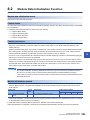
Module Data Initialization Function . . . . . . . . . . . . . . . . . . . . . . . . . . . . . . . . . . . . . . . . . . . . . . . . . . . . . . . . 303
8.3
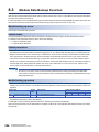
Module Data Backup Function . . . . . . . . . . . . . . . . . . . . . . . . . . . . . . . . . . . . . . . . . . . . . . . . . . . . . . . . . . . . 304
8.4
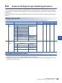
External I/O Signal Logic Switching Function . . . . . . . . . . . . . . . . . . . . . . . . . . . . . . . . . . . . . . . . . . . . . . . 305
8.5
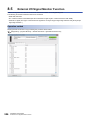
External I/O Signal Monitor Function . . . . . . . . . . . . . . . . . . . . . . . . . . . . . . . . . . . . . . . . . . . . . . . . . . . . . . 306
8.6
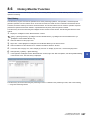
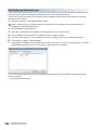
History Monitor Function . . . . . . . . . . . . . . . . . . . . . . . . . . . . . . . . . . . . . . . . . . . . . . . . . . . . . . . . . . . . . . . . 307
CHAPTER 9
9.1
9.2
PARAMETER SETTING
309
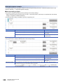
Parameter Setting Procedure . . . . . . . . . . . . . . . . . . . . . . . . . . . . . . . . . . . . . . . . . . . . . . . . . . . . . . . . . . . . . 309
Module Parameters . . . . . . . . . . . . . . . . . . . . . . . . . . . . . . . . . . . . . . . . . . . . . . . . . . . . . . . . . . . . . . . . . . . . . 310
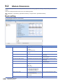
Basic setting . . . . . . . . . . . . . . . . . . . . . . . . . . . . . . . . . . . . . . . . . . . . . . . . . . . . . . . . . . . . . . . . . . . . . . . . . . . 310
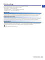
Application setting . . . . . . . . . . . . . . . . . . . . . . . . . . . . . . . . . . . . . . . . . . . . . . . . . . . . . . . . . . . . . . . . . . . . . . . 313
CONTENTS
CHAPTER 8
Interrupt setting . . . . . . . . . . . . . . . . . . . . . . . . . . . . . . . . . . . . . . . . . . . . . . . . . . . . . . . . . . . . . . . . . . . . . . . . . 314
Refresh settings. . . . . . . . . . . . . . . . . . . . . . . . . . . . . . . . . . . . . . . . . . . . . . . . . . . . . . . . . . . . . . . . . . . . . . . . . 315
9.3
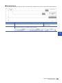
Module Extension Parameter . . . . . . . . . . . . . . . . . . . . . . . . . . . . . . . . . . . . . . . . . . . . . . . . . . . . . . . . . . . . . 319
Positioning data . . . . . . . . . . . . . . . . . . . . . . . . . . . . . . . . . . . . . . . . . . . . . . . . . . . . . . . . . . . . . . . . . . . . . . . . . 319
Block start data . . . . . . . . . . . . . . . . . . . . . . . . . . . . . . . . . . . . . . . . . . . . . . . . . . . . . . . . . . . . . . . . . . . . . . . . . 322
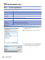
CHAPTER 10 MONITORING/TEST
324
10.1
Positioning Monitor. . . . . . . . . . . . . . . . . . . . . . . . . . . . . . . . . . . . . . . . . . . . . . . . . . . . . . . . . . . . . . . . . . . . . 324
10.2
Positioning Test. . . . . . . . . . . . . . . . . . . . . . . . . . . . . . . . . . . . . . . . . . . . . . . . . . . . . . . . . . . . . . . . . . . . . . . . 326
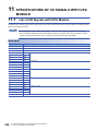
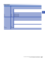
CHAPTER 11 SPECIFICATIONS OF I/O SIGNALS WITH CPU MODULE
336
11.1
List of I/O Signals with CPU Module . . . . . . . . . . . . . . . . . . . . . . . . . . . . . . . . . . . . . . . . . . . . . . . . . . . . . . . 336
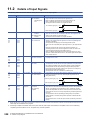
11.2
Details of Input Signals. . . . . . . . . . . . . . . . . . . . . . . . . . . . . . . . . . . . . . . . . . . . . . . . . . . . . . . . . . . . . . . . . . 338
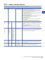
11.3
Details of Output Signals . . . . . . . . . . . . . . . . . . . . . . . . . . . . . . . . . . . . . . . . . . . . . . . . . . . . . . . . . . . . . . . . 339
CHAPTER 12 DATA USED FOR POSITIONING CONTROL
12.1
340
Types of Data . . . . . . . . . . . . . . . . . . . . . . . . . . . . . . . . . . . . . . . . . . . . . . . . . . . . . . . . . . . . . . . . . . . . . . . . . . 340
Parameters and data required for the control . . . . . . . . . . . . . . . . . . . . . . . . . . . . . . . . . . . . . . . . . . . . . . . . . . 340
Setting items for positioning parameters . . . . . . . . . . . . . . . . . . . . . . . . . . . . . . . . . . . . . . . . . . . . . . . . . . . . . . 342
Setting items for OPR parameters. . . . . . . . . . . . . . . . . . . . . . . . . . . . . . . . . . . . . . . . . . . . . . . . . . . . . . . . . . . 349
Setting items for positioning data . . . . . . . . . . . . . . . . . . . . . . . . . . . . . . . . . . . . . . . . . . . . . . . . . . . . . . . . . . . 350
Block start data setting items. . . . . . . . . . . . . . . . . . . . . . . . . . . . . . . . . . . . . . . . . . . . . . . . . . . . . . . . . . . . . . . 352
Setting items for condition data . . . . . . . . . . . . . . . . . . . . . . . . . . . . . . . . . . . . . . . . . . . . . . . . . . . . . . . . . . . . . 353
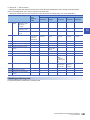
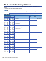
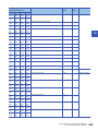
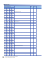
12.2
List of Buffer Memory Addresses . . . . . . . . . . . . . . . . . . . . . . . . . . . . . . . . . . . . . . . . . . . . . . . . . . . . . . . . . 354
12.3
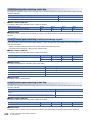
Basic Setting . . . . . . . . . . . . . . . . . . . . . . . . . . . . . . . . . . . . . . . . . . . . . . . . . . . . . . . . . . . . . . . . . . . . . . . . . . 374
Basic parameter 1 . . . . . . . . . . . . . . . . . . . . . . . . . . . . . . . . . . . . . . . . . . . . . . . . . . . . . . . . . . . . . . . . . . . . . . . 374
Basic parameter 2 . . . . . . . . . . . . . . . . . . . . . . . . . . . . . . . . . . . . . . . . . . . . . . . . . . . . . . . . . . . . . . . . . . . . . . . 383
Detailed parameter 1 . . . . . . . . . . . . . . . . . . . . . . . . . . . . . . . . . . . . . . . . . . . . . . . . . . . . . . . . . . . . . . . . . . . . . 385
Detailed parameter 2 . . . . . . . . . . . . . . . . . . . . . . . . . . . . . . . . . . . . . . . . . . . . . . . . . . . . . . . . . . . . . . . . . . . . . 394
OPR basic parameter . . . . . . . . . . . . . . . . . . . . . . . . . . . . . . . . . . . . . . . . . . . . . . . . . . . . . . . . . . . . . . . . . . . . 403
OPR detailed parameter . . . . . . . . . . . . . . . . . . . . . . . . . . . . . . . . . . . . . . . . . . . . . . . . . . . . . . . . . . . . . . . . . . 408
12.4
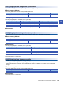
Positioning Data . . . . . . . . . . . . . . . . . . . . . . . . . . . . . . . . . . . . . . . . . . . . . . . . . . . . . . . . . . . . . . . . . . . . . . . 414
12.5
Block Start Data . . . . . . . . . . . . . . . . . . . . . . . . . . . . . . . . . . . . . . . . . . . . . . . . . . . . . . . . . . . . . . . . . . . . . . . . 428
12.6
Condition Data . . . . . . . . . . . . . . . . . . . . . . . . . . . . . . . . . . . . . . . . . . . . . . . . . . . . . . . . . . . . . . . . . . . . . . . . . 433
15
12.7
Monitor Data. . . . . . . . . . . . . . . . . . . . . . . . . . . . . . . . . . . . . . . . . . . . . . . . . . . . . . . . . . . . . . . . . . . . . . . . . . . 437
System monitor data . . . . . . . . . . . . . . . . . . . . . . . . . . . . . . . . . . . . . . . . . . . . . . . . . . . . . . . . . . . . . . . . . . . . . 437
Axis monitor data. . . . . . . . . . . . . . . . . . . . . . . . . . . . . . . . . . . . . . . . . . . . . . . . . . . . . . . . . . . . . . . . . . . . . . . . 447
12.8
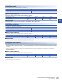
Control Data . . . . . . . . . . . . . . . . . . . . . . . . . . . . . . . . . . . . . . . . . . . . . . . . . . . . . . . . . . . . . . . . . . . . . . . . . . . 461
System control data. . . . . . . . . . . . . . . . . . . . . . . . . . . . . . . . . . . . . . . . . . . . . . . . . . . . . . . . . . . . . . . . . . . . . . 461
Axis control data . . . . . . . . . . . . . . . . . . . . . . . . . . . . . . . . . . . . . . . . . . . . . . . . . . . . . . . . . . . . . . . . . . . . . . . . 463
12.9
Interrupt Setting. . . . . . . . . . . . . . . . . . . . . . . . . . . . . . . . . . . . . . . . . . . . . . . . . . . . . . . . . . . . . . . . . . . . . . . . 477
12.10 Synchronized Refresh-dedicated Area . . . . . . . . . . . . . . . . . . . . . . . . . . . . . . . . . . . . . . . . . . . . . . . . . . . . . 479
12.11 Basic Parameter 3 . . . . . . . . . . . . . . . . . . . . . . . . . . . . . . . . . . . . . . . . . . . . . . . . . . . . . . . . . . . . . . . . . . . . . . 480
12.12 Parameter Reflection. . . . . . . . . . . . . . . . . . . . . . . . . . . . . . . . . . . . . . . . . . . . . . . . . . . . . . . . . . . . . . . . . . . . 481
CHAPTER 13 PROGRAMMING
483
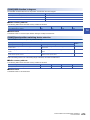
13.1
Precautions on Programming . . . . . . . . . . . . . . . . . . . . . . . . . . . . . . . . . . . . . . . . . . . . . . . . . . . . . . . . . . . . 483
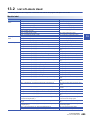
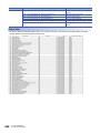
13.2
List of Labels Used . . . . . . . . . . . . . . . . . . . . . . . . . . . . . . . . . . . . . . . . . . . . . . . . . . . . . . . . . . . . . . . . . . . . . 485
13.3
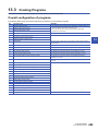
Creating Programs . . . . . . . . . . . . . . . . . . . . . . . . . . . . . . . . . . . . . . . . . . . . . . . . . . . . . . . . . . . . . . . . . . . . . 489
Overall configuration of programs . . . . . . . . . . . . . . . . . . . . . . . . . . . . . . . . . . . . . . . . . . . . . . . . . . . . . . . . . . . 489
13.4
Program Example . . . . . . . . . . . . . . . . . . . . . . . . . . . . . . . . . . . . . . . . . . . . . . . . . . . . . . . . . . . . . . . . . . . . . . 490
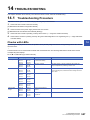
CHAPTER 14 TROUBLESHOOTING
14.1
507
Troubleshooting Procedure . . . . . . . . . . . . . . . . . . . . . . . . . . . . . . . . . . . . . . . . . . . . . . . . . . . . . . . . . . . . . . 507
Checks with LEDs . . . . . . . . . . . . . . . . . . . . . . . . . . . . . . . . . . . . . . . . . . . . . . . . . . . . . . . . . . . . . . . . . . . . . . . 507
Check of module status . . . . . . . . . . . . . . . . . . . . . . . . . . . . . . . . . . . . . . . . . . . . . . . . . . . . . . . . . . . . . . . . . . . 508
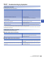
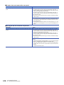
14.2
14.3
Troubleshooting by Symptom . . . . . . . . . . . . . . . . . . . . . . . . . . . . . . . . . . . . . . . . . . . . . . . . . . . . . . . . . . . . 509
Error and Warning Details . . . . . . . . . . . . . . . . . . . . . . . . . . . . . . . . . . . . . . . . . . . . . . . . . . . . . . . . . . . . . . . 511
Error type. . . . . . . . . . . . . . . . . . . . . . . . . . . . . . . . . . . . . . . . . . . . . . . . . . . . . . . . . . . . . . . . . . . . . . . . . . . . . . 511
Error code classification . . . . . . . . . . . . . . . . . . . . . . . . . . . . . . . . . . . . . . . . . . . . . . . . . . . . . . . . . . . . . . . . . . 512
Error storage . . . . . . . . . . . . . . . . . . . . . . . . . . . . . . . . . . . . . . . . . . . . . . . . . . . . . . . . . . . . . . . . . . . . . . . . . . . 512
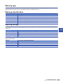
Warning type . . . . . . . . . . . . . . . . . . . . . . . . . . . . . . . . . . . . . . . . . . . . . . . . . . . . . . . . . . . . . . . . . . . . . . . . . . . 513
Warning classification . . . . . . . . . . . . . . . . . . . . . . . . . . . . . . . . . . . . . . . . . . . . . . . . . . . . . . . . . . . . . . . . . . . . 513
Warning storage . . . . . . . . . . . . . . . . . . . . . . . . . . . . . . . . . . . . . . . . . . . . . . . . . . . . . . . . . . . . . . . . . . . . . . . . 513
Clearing errors or warnings . . . . . . . . . . . . . . . . . . . . . . . . . . . . . . . . . . . . . . . . . . . . . . . . . . . . . . . . . . . . . . . . 514
14.4
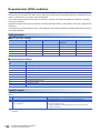
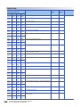
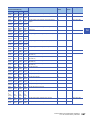
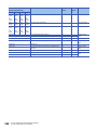
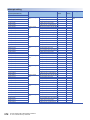
List of Warning Codes . . . . . . . . . . . . . . . . . . . . . . . . . . . . . . . . . . . . . . . . . . . . . . . . . . . . . . . . . . . . . . . . . . 515
14.5
List of Error Codes . . . . . . . . . . . . . . . . . . . . . . . . . . . . . . . . . . . . . . . . . . . . . . . . . . . . . . . . . . . . . . . . . . . . . 519
APPENDICES
540
Appendix 1 Module Label . . . . . . . . . . . . . . . . . . . . . . . . . . . . . . . . . . . . . . . . . . . . . . . . . . . . . . . . . . . . . . . . . . . . . 540
Appendix 2 Dedicated Instruction . . . . . . . . . . . . . . . . . . . . . . . . . . . . . . . . . . . . . . . . . . . . . . . . . . . . . . . . . . . . . . 542
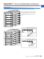
Appendix 3 How to Find Buffer Memory Addresses. . . . . . . . . . . . . . . . . . . . . . . . . . . . . . . . . . . . . . . . . . . . . . . . 543
Appendix 4 Added or Changed Functions. . . . . . . . . . . . . . . . . . . . . . . . . . . . . . . . . . . . . . . . . . . . . . . . . . . . . . . . 548
INDEX
550
REVISIONS . . . . . . . . . . . . . . . . . . . . . . . . . . . . . . . . . . . . . . . . . . . . . . . . . . . . . . . . . . . . . . . . . . . . . . . . . . . . .554
WARRANTY . . . . . . . . . . . . . . . . . . . . . . . . . . . . . . . . . . . . . . . . . . . . . . . . . . . . . . . . . . . . . . . . . . . . . . . . . . . .555
TRADEMARKS . . . . . . . . . . . . . . . . . . . . . . . . . . . . . . . . . . . . . . . . . . . . . . . . . . . . . . . . . . . . . . . . . . . . . . . . . .556
16
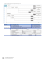
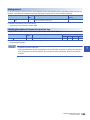
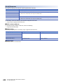
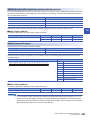
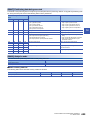
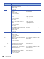
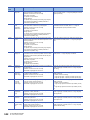
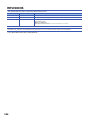
RELEVANT MANUALS
Manual name [manual number]
Description
Available form
MELSEC iQ-R Positioning Module User's Manual (Application)
[SH-081245ENG] (this manual)
Functions, parameter settings, I/O signals, buffer memory,
programming, and troubleshooting of the positioning module
Print book
MELSEC iQ-R Positioning Module User's Manual (Startup)
[SH-081243ENG]
System configuration, specifications, procedures before operation,
wiring, and operation examples of the positioning module
Print book
MELSEC iQ-R Programming Manual (Instructions, Standard
Functions/Function Blocks)
[SH-081266ENG]
Instructions for the CPU module, dedicated instructions for the
intelligent function modules, and standard functions/function
blocks
e-Manual
EPUB
PDF
e-Manual
EPUB
PDF
e-Manual
EPUB
PDF
This manual does not include information on the module function blocks.
For details, refer to the Function Block Reference for the module used.
e-Manual refers to the Mitsubishi FA electronic book manuals that can be browsed using a dedicated tool.
e-Manual has the following features:
• Required information can be cross-searched in multiple manuals.
• Other manuals can be accessed from the links in the manual.
• The hardware specifications of each part can be found from the product figures.
• Pages that users often browse can be bookmarked.
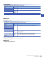
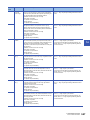
TERMS
Unless otherwise specified, this manual uses the following terms.
Term
Description
GX Works3
The product name of the software package for the MELSEC programmable controllers
Q series-compatible mode
A mode where the module operates with the start time of 1.5ms. The mode is to match the start time to the
QD75N or LD75.
RD75
The abbreviation for the MELSEC iQ-R series positioning module
RD75P
A generic term for the positioning module RD75P2 and RD75P4
RD75D
A generic term for the positioning module RD75D2 and RD75D4
Engineering tool
Another term for GX Works3
Global label
A label that is valid for all the program data when multiple program data are created in the project. The global
label has two types: a module specific label (module label), which is generated automatically by GX Works3, and
an optional label, which can be created for any specified device.
Quick start mode
A mode where the module operates with the start time of 0.3ms. Unless otherwise specified, the functions
described in this manual are for when quick start mode is set.
Drive unit (servo amplifier)
A unit that amplifies pulses that are output from the positioning module to control a motor. The unit is provided
with a servomotor or stepping motor. It is also called a servo amplifier.
Module label
A label that represents one of memory areas (I/O signals and buffer memory areas) specific to each module in a
given character string. For the module used, GX Works3 automatically generates this label, which can be used
as a global label.
17
1
STARTING AND STOPPING
This chapter describes how to start and stop positioning control operations with the RD75.
1.1
Starting
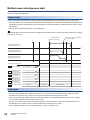
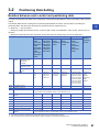
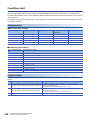
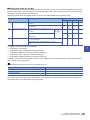
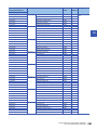
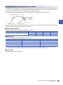
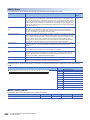
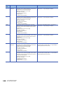
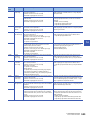
The RD75 starts the positioning control when a start trigger, specific to the control, is turned on. The following table lists the
start signals by control type. This section describes starting with Positioning start signal [Y10, Y11, Y12, Y13] and an external
command signal.
Control details
Start trigger
Major positioning control
• Turn on Positioning start signal [Y10, Y11, Y12, Y13].
• Execute the GP.PSTRT instruction.
• Turn on an external command signal (CHG).
Advanced positioning control
OPR control
Manual control
JOG operation
Inching operation
Manual pulse
generator operation
Turn on Forward run JOG start signal [Y8, YA, YC, YE] or Reverse run JOG start signal [Y9, YB, YD,
YF].
Manipulate a manual pulse generator.
For the controls other than the manual controls, any one of the following start modes can be selected.
• Normal start (Page 21 Normal start)
• Quick start (Page 23 Quick start)
• Multiple axes simultaneous start (Page 28 Multiple axes simultaneous start)
The target position for a control can be specified using positioning data, Block start data, and condition data. Available data
depends on the selected start mode.
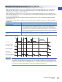
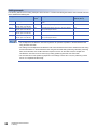
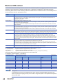
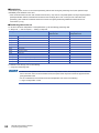
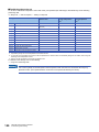
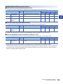
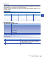
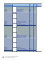
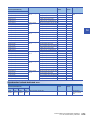
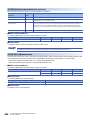
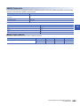
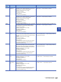
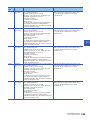
Start condition
Satisfy the following conditions to start a program. In addition, set the required conditions in the program to prevent an
operation from starting if the conditions are not satisfied.
Signal name
Signal status
Device
Axis 1
I/O signals
External signal
*1
18
Axis 2
Axis 3
Axis 4
PLC READY signal
ON
The CPU module is ready.
Y0
RD75 READY signal
ON
RD75 READY signal
X0
Module access flag*1
ON
The RD75 buffer memory can be
accessed.
X1
Axis stop signal
OFF
Axis stop signal is off.
Y4
Y5
Y6
Y7
M code ON signal
OFF
M code ON signal is off.
X4
X5
X6
X7
Error detection signal
OFF
No error has been detected.
X8
X9
XA
XB
BUSY signal
OFF
BUSY signal is off.
XC
XD
XE
XF
Start complete signal
OFF
Start complete signal is off.
X10
X11
X12
X13
Drive unit READY signal (READY)
ON
The drive unit is ready.
Stop signal (STOP)
OFF
Stop signal is off.
Upper limit signal (FLS)
ON
The current position is within the limit.
Lower limit signal (RLS)
ON
The current position is within the limit.
The interlock must be provided so that the buffer memory is accessed after Module access flag [X1] turns on. When no interlock is
provided, the buffer memory may be accessed while the module parameter and module extension parameter that are sent from the CPU
module are updated. If the buffer memory is accessed during the update, an unexpected value may be read or written.
1 STARTING AND STOPPING
1.1 Starting
Starting with Positioning start signal [Y10, Y11, Y12, Y13]
1
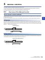
This section describes operations started with Positioning start signal [Y10, Y11, Y12, Y13].
• When Positioning start signal [Y10, Y11, Y12, Y13] is turned on, Start complete signal [X10, X11, X12, X13] and BUSY
signal [XC, XD, XE, XF] turn on, and the positioning operation starts. The on state of BUSY signal [XC, XD, XE, XF]
indicates that the corresponding axis is in operation.
• When Positioning start signal [Y10, Y11, Y12, Y13] is turned off, Start complete signal [X10, X11, X12, X13] turns off. If
Positioning start signal [Y10, Y11, Y12, Y13] remains on even after the positioning is completed, Start complete signal [X10,
X11, X12, X13] also remains on.
• If Positioning start signal is turned on again while BUSY signal [XC, XD, XE, XF] is on, Start during operation (Warning
code: 0900H) occurs.
• The operation performed after the completion of the positioning operation depends on whether or not the next positioning
control is set.
Presence or absence of the next
positioning control
Processing
When the next positioning control is performed
• If [Da.9] Dwell time is set, the RD75 waits for the set time to elapse, and the positioning will be completed.
• When the positioning has been completed, BUSY signal [XC, XD, XE, XF] turns off and Positioning
complete signal [X14, X15, X16, X17] turns on. However, when the speed control has been used or the
ON time of Positioning complete signal is 0, Positioning complete signal [X14, X15, X16, X17] does not
turn on.
• When the time set in [Pr.40] Positioning complete signal output time elapses, Positioning complete signal
[X14, X15, X16, X17] turns off.
When the next positioning control is not
performed
• If [Da.9] Dwell time is set, the RD75 waits for the set time to elapse.
• When the time set in [Da.9] Dwell time elapses, the next positioning control starts.
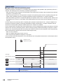
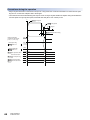
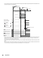
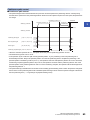
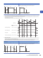
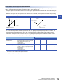
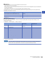
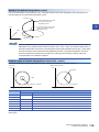
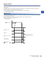
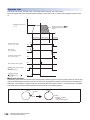
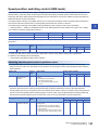
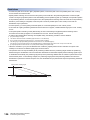
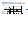
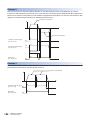
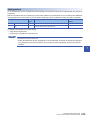
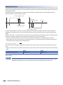
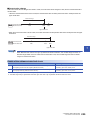
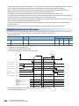
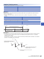
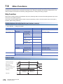
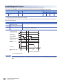
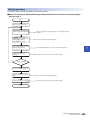
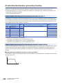
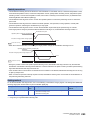
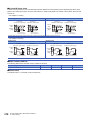
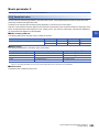
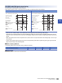
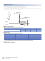
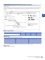
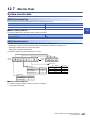
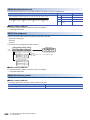
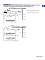
■Time chart for starting
V
Dwell time
t
Positioning
ON
Positioning start signal
[Y10, Y11, Y12, Y13]
OFF
Start complete signal
[X10, X11, X12, X13]
OFF
BUSY signal
[XC, XD, XE, XF]
OFF
ON
ON
ON
Positioning complete signal OFF
[X14, X15, X16, X17]
Even when the positioning control of a movement amount 0 is performed, BUSY signal [XC, XD, XE, XF] turns
on. However, since the ON time of the signal is short, the ON state of the signal may not be detected in the
program. (The on state of Start complete signal [X10, X11, X12, X13], Positioning complete signal [X14, X15,
X16, X17], and M code ON signal [X4, X5, X6, X7] can be detected in the program.)
1 STARTING AND STOPPING
1.1 Starting
19
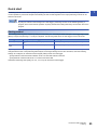
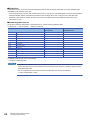
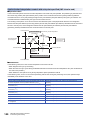
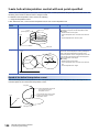
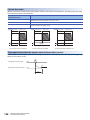
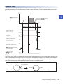
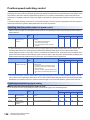
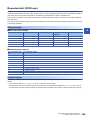
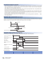
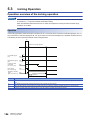
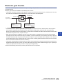
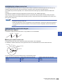
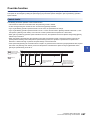
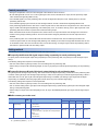
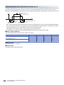
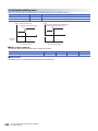
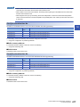
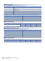
Starting by inputting an external command signal (CHG)
When the positioning control is started by inputting an external command signal (CHG), the start command can be directly
input to the RD75. This method eliminates the variation time equivalent to one scan time of the CPU module. Use the start
command when an operation is required to be started as soon as possible, or when the starting variation time is to be
suppressed.
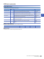
■Starting method
To start the positioning with the external command signal, set [Pr.42] External command function selection beforehand, and
validate [Cd.8] External command valid using a program. After setting those two areas, turn on an external command signal
(CHG).
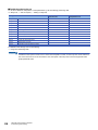
Setting item
Setting
value
Setting detail
Buffer memory address
Axis 1
Axis 2
Axis 3
Axis 4
[Pr.42]
External command function
selection
0
Set 0: Start with external command.
62
212
362
512
[Cd.8]
External command valid
1
Set 1: Validate external command.
1505
1605
1705
1805
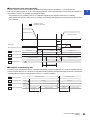
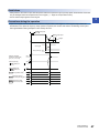
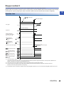
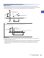
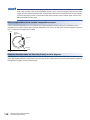
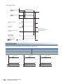
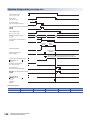
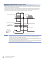
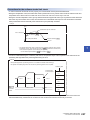
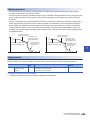
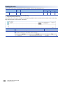
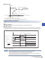
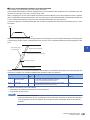
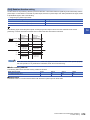
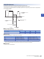
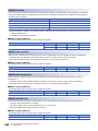
■Restrictions
When starting by inputting an external command signal (CHG), Start complete signal [X10, X11, X12, X13] does not turn on.
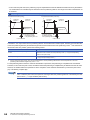
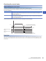
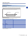
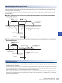
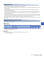
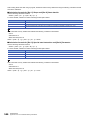
■Time chart for starting
Operation pattern
Dwell time
v
Positioning data No.
1(00)
t
Positioning start signal [Y10]
PLC READY signal
[Y0]
RD75 READY signal
[X0]
Start complete signal
[X10]
BUSY signal
[XC]
Positioning complete
signal
[X14]
Error detection signal
[X8]
External command signal
(externally)
Pr.42
External command
function selection
0
Cd.3 Positioning start No.
Cd.8 External command
valid
20
1 STARTING AND STOPPING
1.1 Starting
1
1
0
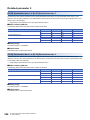
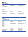
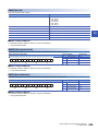
Normal start
1
Positioning controls can be started by the simplest procedure in this mode. Major positioning controls and advanced
positioning controls can be started in this mode.
The following positioning data is used.
• Positioning data (No.1 to No.600)
• Block start data (No.7000 to No.7004)
• Machine OPR (No.9001)
• Fast OPR (No.9002)
• Current value change (No.9003)
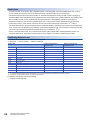
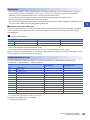
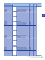
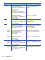
Starting method
After setting positioning data, input a start trigger to start the specified positioning data. The following table lists the start
triggers used in this mode.
Start trigger name
Starting method (Start trigger)
Positioning data to be started
Positioning start signal
Turning off and on Positioning start signal [Y10, Y11, Y12,
Y13]
Starts the positioning data specified in [Cd.3] Positioning start No.
External command
signal
Turning off and on an external command signal (CHG)
Starts the positioning data specified in [Cd.3] Positioning start No.
Dedicated instruction
Executing the GP.PSTRT instruction
Starts the positioning data specified as the control data.
1 STARTING AND STOPPING
1.1 Starting
21
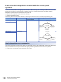
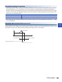
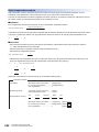
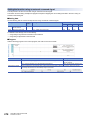
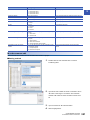
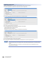
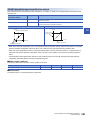
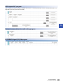
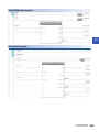
Program example
This section shows program examples of the normal start for each command trigger.
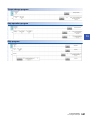
■For module FB
For the program example using the module FB, refer to the following.
Page 497 Positioning start program
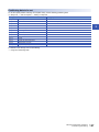
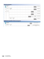
■For Positioning start signal [Y10, Y11, Y12, Y13]
Classification
Module label
Global label, local label
Label Name
Description
RD75_1.bnErrorDetection_Axis[0]
Axis 1 Error detection signal [X8]
RD75_1.bnBusy_Axis[0]
Axis 1 BUSY signal [XC]
RD75_1.bnStartComplete_Axis[0]
Axis 1 Start complete signal [X10]
RD75_1.bnPositioningStart_Axis[0]
Axis 1 Positioning start signal [Y10]
RD75_1.stnAxisControlData_Axis_D[0].uPositioningStartNo_D
Axis 1 [Cd.3] Positioning start No.
Define the global label or local label as follows. Setting Assign (Device/Label) for labels is not necessary because the unused
internal relay and data device are automatically assigned to the labels.
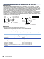
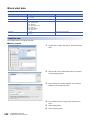
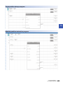
■For External command signal (CHG)
Positioning can be started by setting 0: Start with external command in [Pr.42] External command function selection and
inputting External command signal (CHG) after executing the following program.
Page 495 External command function valid setting program
22
1 STARTING AND STOPPING
1.1 Starting
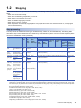
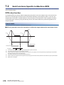
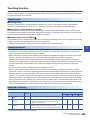
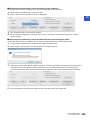
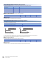
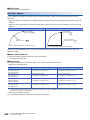
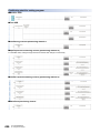
Quick start
1
Positioning controls can be started quickly by analyzing in advance the positioning data executed immediately after the
current operation to prevent the analysis time affecting the start. Positioning data for the major positioning controls can be
started in this mode.
By using an external command signal as a start trigger, positioning controls can be started bypassing a
program, which means that the operation is quickly started without being affected by the execution time of the
program.
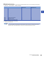
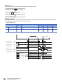
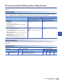
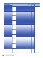
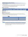
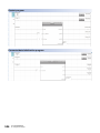
Starting method
After setting positioning data, set [Cd.43] Analysis mode setting to 1: Pre-analysis mode and input a start trigger signal while
[Md.61] Analysis complete flag is 1: Analysis completed. The following table shows the start triggers used in this mode.
Start trigger name
Starting method (Start trigger)
Positioning data to be started
Positioning start signal
Turning off and on Positioning start signal [Y10, Y11, Y12,
Y13]
Starts the positioning data specified in [Cd.3] Positioning start No.
External command
signal
Turning off and on an external command signal (CHG)
Starts the positioning data specified in [Cd.3] Positioning start No.
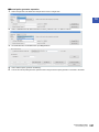
Depending on the start timing of the positioning data analysis, a start trigger used is determined. Even if the settings are
changed after the start of the positioning data analysis, the changed settings are not valid. Therefore, when the following
settings are configured, an external command signal (CHG) is used as a start trigger.
• [Pr.42] External command function selection is set to 0: Start with external command.
• [Cd.8] External command valid is set to 1: External command valid.
Otherwise, Positioning start signal [Y10, Y11, Y12, Y13] can be used as a start trigger.
1 STARTING AND STOPPING
1.1 Starting
23
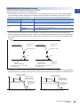
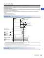
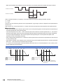
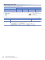
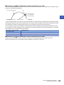
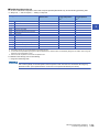
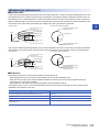
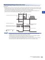
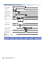
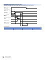
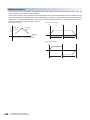
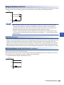
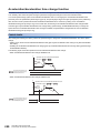
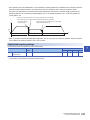
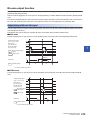
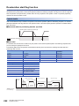
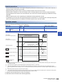
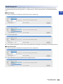
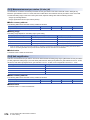
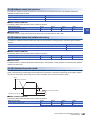
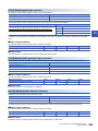
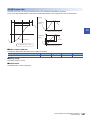
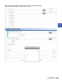
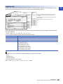
Control details
■Length of time before the positioning starts
While [Cd.43] Analysis mode setting is 1: Pre-analysis mode, the positioning data specified in [Cd.3] Positioning start No. is
analyzed. The following shows the start timing of positioning data analysis.
• When the analysis mode is changed to the pre-analysis mode (Timing when the setting of [Cd.43] Analysis mode setting is
changed to 1: Pre-analysis mode)
• When the positioning start No. is changed after the analysis of the positioning data has been completed (Timing when the
setting of [Cd.3] Positioning start No. is changed while [Md.61] Analysis complete flag is 1: Analysis completed)
• When the positioning operation is completed and [Md.26] Axis operation status turns to 0: Standby However, When M code
ON signal [X4, X5, X6, X7] is on, the analysis of the positioning data will not start until M code ON signal [X4, X5, X6, X7]
turns off.
Once the analysis of the positioning data is completed, [Md.61] Analysis complete flag turns to 1: Analysis completed. The
quick start is executed by inputting a start trigger while [Md.61] Analysis complete flag is 1: Analysis completed. After the
quick start is executed, [Md.61] Analysis complete flag turns to 0: Analysis not completed.
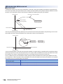
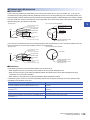
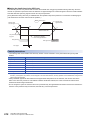
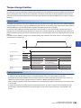
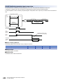
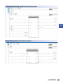
The pre-analysis mode is changed to the normal analysis mode not only by setting [Cd.43] Analysis mode setting to 0: Normal
analysis mode, but also by the following factors. When the setting of [Cd.43] Analysis mode setting is changed to 0: Normal
analysis mode, the positioning data which has already been analyzed is cleared. (In the interpolation control, the positioning
data is cleared when the reference axis enters the normal analysis mode.)
• When an error is detected
• When PLC READY signal [Y0] is turned on and off
• When the positioning operation is stopped by a stop signal
If any of the three causes described above occurs, the reference axis or interpolation axis enters the normal analysis mode in
the interpolation control.
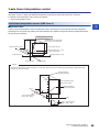
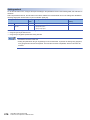
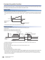
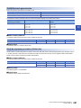
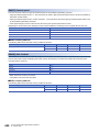
v
Operation by a user
Operation by the system
t
t2
ON
Start trigger
OFF
BUSY signal [XC, XD, XE, XF]
Md.26 Axis operation status
Standby
Analyzing
Cd.43 Analysis mode setting 0: Normal analysis mode
Md.61 Analysis complete flag
Position control
1: Pre-analysis mode
0: Analysis not completed
1: Analysis completed
t1
t1
t2
0.88 to 1.77ms
External command signal: 20s
Positioning start signal: 8s
0: Analysis not completed
Waiting for a start trigger
The shortest time between the completion of the positioning control and the starting of the next positioning control is t1 + t2.
24
1 STARTING AND STOPPING
1.1 Starting
■Executing the quick start repeatedly
The quick start can be executed repeatedly by remaining [Cd.43] Analysis mode setting to 1: Pre-analysis mode.
1
When [Cd.3] Positioning start No. is set to the positioning data No. used for the positioning control 2 during the operation of
the positioning control 1, the operation is performed as follows.
• The positioning by the positioning control 1 is completed and [Md.26] Axis operation status turns to 0: Standby.
• When [Md.26] Axis operation status turns to 0: Standby, the positioning data specified in [Cd.3] Positioning start No. starts
to be analyzed.
v
Operation by a user
Operation by the system
Positioning control 1
Positioning control 2
t
t2
Start trigger
BUSY signal [XC, XD, XE, XF]
Md.26 Axis operation status
Position control
Standby
Analyzing
Cd.43 Analysis mode setting
Position control
1: Pre-analysis mode
0: Analysis not completed
Md.61 Analysis complete flag
Cd.3 Positioning start No.
1: Analysis completed
0: Analysis not completed
Positioning data No. used for positioning control 2
t1
Waiting for a start trigger
■Reanalysis of positioning data
The setting of [Cd.3] Positioning start No. is changed while [Md.61] Analysis complete flag is 1: Analysis completed, [Md.61]
Analysis complete flag turns to 0: Analysis not completed and the positioning data will be reanalyzed. When the reanalysis is
completed, [Md.61] Analysis complete flag turns again to 1: Analysis completed.
Cd.3 Positioning start No.
Md.26 Axis operation status
Cd.43 Analysis mode setting
Md.61 Analysis complete flag
Positioning data No.A
Standby
Positioning data No.B
Analyzing
0: Normal
analysis mode
Analyzing
1: Pre-analysis mode
0: Analysis not completed
t1
1: Analysis completed
0: Analysis not
completed
1: Analysis completed
t1
1 STARTING AND STOPPING
1.1 Starting
25
Restrictions
• The range of the positioning data Nos. used for the quick start is between 1 and 600. If a number other than 1 to 600 is set
for [Cd.3] Positioning start No., Pre-analysis not possible (Warning code: 09A8H) occurs and the pre-analysis of positioning
data is not performed. However, by inputting a start trigger signal, positioning data is analyzed before the positioning is
started, just as in the normal analysis mode. In this case, the setting in [Cd.43] Analysis mode setting remains 1: Preanalysis mode.
• In the pre-analysis mode, restarting is not allowed. To allow restarting, turn on a stop signal and change the analysis mode
to the normal analysis mode. If the analysis mode is changed again to the pre-analysis mode after changed to the preanalysis mode and restarting is attempted, Restart not possible (Error code: 090BH) occurs and restarting cannot be
executed.
• In the pre-analysis mode, the step function cannot be used. Even if [Cd.35] Step valid flag is 1: Carry out step operation
while positioning data is being analyzed, Step start disabled (Warning code: 09A6H) occurs and the normal operation is
performed with the setting ignored. (The step operation does not stop.)
• In the pre-analysis mode, the pre-reading start function cannot be used. The setting of Execution prohibition flag [Y14, Y15,
Y16, Y17] is ignored.
• In the pre-analysis mode, the manual control cannot be used. Starting the manual control causes Manual control start in
pre-analysis mode (Warning code: 09A4H), and the manual control does not start.
Precautions
• If a start trigger is input while [Md.61] Analysis complete flag is 0: Analysis not completed, Pre-analysis incomplete start
(Warning code: 09A2H) occurs and the positioning will be started after the analysis of the positioning data is completed.
• When [Md.61] Analysis complete flag is set to 1: Analysis completed, errors are detected at intervals of 0.88ms. Thus, if a
start trigger is input within 0.88ms after the occurrence of an error, the operation may be started. In this case, the error is
detected immediately after the start, and the operation stops.
• The data reflected to basic parameter 2, detailed parameter 2, and positioning data is the one in the buffer memory at the
start of the analysis of positioning data. Therefore, even if a set value of basic parameter 2 and other data is changed after
the analysis of positioning data has been completed (When [Md.61] Analysis complete flag is 1: Analysis completed), the
value is not reflected to the control. To reflect the set value, conduct a reanalysis by changing the setting of [Cd.3]
Positioning start No. or using other methods.
The analysis of positioning data is performed by checking the settings of [Cd.43] Analysis mode setting and
[Cd.3] Positioning start No. at intervals of 0.88ms. Thus, set [Cd.43] Analysis mode setting and [Cd.3]
Positioning start No. beforehand so that the analysis starts 0.88ms earlier than the desired start timing and
earlier than a length of time longer than the analysis time for the positioning data. The analysis time for the
positioning data is approximately equal to the start time.
• For all the axes to which the quick start is performed, set [Cd.43] Analysis mode setting to 1: Pre-analysis mode. If 1: Preanalysis mode is set for the reference axis and 0: Normal analysis mode is set for the interpolation axes, Pre-analysis not
possible (Warning code: 09A9H) occurs and the pre-analysis of positioning data is not performed. However, by inputting a
start trigger signal, positioning data is analyzed before the positioning is started, just as in the normal analysis mode. In this
case, the setting in [Cd.43] Analysis mode setting remains 1: Pre-analysis mode.
• In the pre-analysis mode, the analysis of positioning data is performed in ascending order of axis numbers. For axes that do
not require the analysis of positioning data, such as an axis to be interpolated, setting [Cd.3] Positioning start No. to 0 is
recommended. Because the analysis of positioning data is not performed for the axes for which 0 is set, the time that
elapses until the positioning start is cut off.
• When [Pr.42] External command function selection is set to 0: Start with external command and [Cd.8] External command
valid is set to 1: External command valid in the pre-analysis mode, do not turn off and on Positioning start signal [Y10, Y11,
Y12, Y13]. Positioning start signal input at quick external start (Warning code: 09A7H) occurs and no operation is started.
• When [Pr.42] External command function selection is set to a value other than 0: Start with external command in the preanalysis mode, an external command signal is disabled for 1.77ms maximum after start starting. Input an external
command signal 1.77ms or longer after starting.
26
1 STARTING AND STOPPING
1.1 Starting
■Precautions for the processing performed at the pre-analysis of positioning data
The following table lists the processing performed at the pre-analysis of positioning data.
Major positioning control
Position control
1-axis linear control
2-axis linear interpolation control
3-axis linear interpolation control
4-axis linear interpolation control
1-axis fixed-feed control
2-axis fixed-feed control
3-axis fixed-feed control
4-axis fixed-feed control
• Clearing the axis control data
• Initializing the axis monitor data
• Turning off Positioning complete signal [X14, X15, X16, X17]
•
•
•
•
•
Clearing the axis control data
Initializing the axis monitor data
Turning off Positioning complete signal [X14, X15, X16, X17]
Clearing the current feed value to 0
Clearing the values after the decimal point held in the RD75
2-axis circular interpolation
control
• Clearing the axis control data
• Initializing the axis monitor data
• Turning off Positioning complete signal [X14, X15, X16, X17]
3-axis helical interpolation control
• Clearing the axis control data
• Initializing the axis monitor data
• Turning off Positioning complete signal [X14, X15, X16, X17]
1-axis speed control
2-axis speed control
3-axis speed control
4-axis speed control
• Clearing the axis control data
• Initializing the axis monitor data
• Turning off Positioning complete signal [X14, X15, X16, X17]
When [Pr.21] Current feed value during speed control is 2: Clear current feed value to 0, the
following processing is also performed.
• Clearing the current feed value to 0
• Clearing the values after the decimal point held in the RD75
Speed-position switching control
• Clearing the axis control data
• Initializing the axis monitor data
• Turning off Positioning complete signal [X14, X15, X16, X17]
When [Pr.21] Current feed value during speed control is 2: Clear current feed value to 0, the
following processing is also performed.
• Clearing the current feed value to 0
• Clearing the values after the decimal point held in the RD75
Position-speed switching control
Current value change
1
Processing performed at the pre-analysis of positioning data
•
•
•
•
•
Clearing the axis control data
Initializing the axis monitor data
Turning off Positioning complete signal [X14, X15, X16, X17]
Clearing the current feed value to 0
Clearing the values after the decimal point held in the RD75
Note that if [Cd.43] Analysis mode setting is set to 1: Pre-analysis mode and is held, the analysis of the next positioning data
will start immediately after the current positioning operation is completed.
For example, Positioning complete signal [X14, X15, X16, X17] turns on at the completion of positioning and immediately
turns off when the pre-analysis is started at the completion of positioning. Thus, depending on the scan time, the on state of
the signal may not be detected by the program used. If necessary, set 0 in [Cd.3] Positioning start No. after the positioning
starts to avoid the analysis of the next positioning data.
Program example
For the program example of the quick start, refer to the following.
Page 498 Quick start program
1 STARTING AND STOPPING
1.1 Starting
27
Multiple axes simultaneous start
In this starting mode, the simultaneous starting axis and the started axis start outputting pulses at the same timing. Up to four
axes can be started simultaneously.
Control details
Perform the multiple axes simultaneous start by setting the following buffer memory areas and turning on a start trigger.
• Set a start data No. of each simultaneous starting axis (positioning data No. of each axis started simultaneously) in [Cd.30]
Simultaneous starting axis start data No. (axis 1 start data No.) to [Cd.33] Simultaneous starting axis start data No. (axis 4
start data No.).
• Set 9004 to [Cd.3] Positioning start No. for the starting axis.
Ex.
The following figure shows the control when the multiple axes simultaneous start control is performed with the axis 1 (starting
axis), axis 2, and axis 3.
Controls are started
at the same timing.
End of the controls vary depending
on positioning data.
v
Positioning control (axis 1)
(positioning start No.: 1)
t
Positioning control (axis 2)
(positioning start No.: 100)
Positioning control (axis 3)
(positioning start No.: 150)
Positioning start signal [Y10]
Cd.3 Positioning start No.
0
9004
0
1
0
100
0
150
0
0
Simultaneous starting
Cd.30 axis start data No.
(axis 1 start data No.)
Simultaneous starting
Cd.31 axis start data No.
(axis 2 start data No.)
Simultaneous starting
Cd.32 axis start data No.
(axis 3 start data No.)
Simultaneous starting
Cd.33 axis start data No.
(axis 4 start data No.)
Md.26 Axis operation status
Standby
Analyzing
Position control
Restrictions
• If [Cd.30] Simultaneous starting axis start data No. (axis 1 start data No.) to [Cd.33] Simultaneous starting axis start data
No. (axis 4 start data No.) of the started axis are not set, or the set values are outside the setting range, Error before
simultaneous start (Error code: 1991H) occurs and all the simultaneous starting axes will not start.
• If any of the simultaneous starting axes is in the axis BUSY state, Error before simultaneous start (Error code: 1990H)
occurs and all the simultaneous starting axes will not start.
• If an error occurs during the analysis of the positioning data on the simultaneous starting axes, Simultaneous start not
possible (Error code: 199EH) occurs and all the simultaneous starting axes will not start.
• If the simultaneous starting axis is the started axis only, no error or warning occurs.
28
1 STARTING AND STOPPING
1.1 Starting
Procedure
1
The following figure shows the procedure for the multiple axes simultaneous start control.
Set Cd.30 to Cd.33 Simultaneous starting axis
start data No.
Write "9004" in Cd.3 Positioning start No.
Turn on Positioning start signal of the axis to be started.
Setting method
The following table lists the data settings to perform the multiple axes simultaneous start using Positioning start signal. (Set
the axis control data for the starting axis.)
Setting item
Setting
value
Setting detail
Buffer memory address
Axis 1
Axis 2
Axis 3
Axis 4
[Cd.3]
Positioning start No.
9004
Set 9004, the start No. for the multiple axes
simultaneous start control.
1500
1600
1700
1800
[Cd.30]
Simultaneous starting axis start
data No. (axis 1 start data No.)
Set the simultaneous starting axis start data No.
Set 0 for the axis other than the simultaneous starting axis.
1540
1640
1740
1840
[Cd.31]
Simultaneous starting axis start
data No. (axis 2 start data No.)
1541
1641
1741
1841
[Cd.32]
Simultaneous starting axis start
data No. (axis 3 start data No.)
1542
1642
1742
1842
[Cd.33]
Simultaneous starting axis start
data No. (axis 4 start data No.)
1543
1643
1743
1843
For details on the settings, refer to the following.
Page 463 [Cd.3] Positioning start No.
Page 472 [Cd.30] Simultaneous starting axis start data No. (Axis 1 start data No.)
Page 472 [Cd.31] Simultaneous starting axis start data No. (Axis 2 start data No.)
Page 472 [Cd.32] Simultaneous starting axis start data No. (Axis 3 start data No.)
Page 472 [Cd.33] Simultaneous starting axis start data No. (axis 4 start data No.)
1 STARTING AND STOPPING
1.1 Starting
29
Setting example
The following table shows the setting example in which the axis 1 is used as the starting axis and the axis 2 and axis 4 is used
as the simultaneous starting axis.
Setting item
Setting
value
Setting detail
Buffer memory
address (Axis 1)
[Cd.3]
Positioning start No.
9004
Set 9004, the start No. for the multiple axes simultaneous start
control.
1500
[Cd.30]
Simultaneous starting axis start
data No. (axis 1 start data No.)
100
Axis 1 starts the positioning data No.100.
1540
[Cd.31]
Simultaneous starting axis start
data No. (axis 2 start data No.)
200
Immediately after the star of the axis 1, the axis 2 starts the
axis 2 positioning data No.200.
1541
[Cd.32]
Simultaneous starting axis start
data No. (axis 3 start data No.)
0
Will not start simultaneously.
1542
[Cd.33]
Simultaneous starting axis start
data No. (axis 4 start data No.)
300
Immediately after the star of the axis 1, the axis 4 starts the
axis 4 positioning data No.300.
1543
• The multiple axes simultaneous start control performs an operation equivalent to the simultaneous start
using the block start data.
• The setting of the multiple axes simultaneous start control is easier than that of the simultaneous start using
the block start data. For the simultaneous start using the block start data, positioning start data, positioning
data, block start data, and condition data are required to be set. On the other hand, the multiple axes
simultaneous start control can be used only by setting positioning data and axis control data.
• The execution time of the positioning depends on the settings of each axis. Thus, the positioning of each
axis is not completed simultaneously.
30
1 STARTING AND STOPPING
1.1 Starting
1.2
Stopping
1
This section describes the stop control of the positioning. The following events may stop each positioning control by the
RD75.
• When each control ends normally
• When Drive unit READY signal (READY) is turned off
• When an error occurred in the CPU module
• When PLC READY signal [Y0] is turned off
• When an error occurs in the RD75
• When an operation is intentionally stopped (When a stop signal sent from the CPU module is turned on, or a stop signal
from an external device)
Stop processing
The stop controls are classified into three types: deceleration stop, sudden stop, and immediate stop. The following table
describes the stop controls (deceleration stop, sudden stop, and immediate stop) at the occurrence of each stop cause (When
the automatic deceleration control is performed).
Stop cause
Stop
axis
M code
ON
signal
after
stop
[Md.26]
Axis
operation
status
after stop
Stop processing
OPR control
Machine
OPR
control
Fast
OPR
control
Major
positioning
control
Advanced
positioning
control
Manual control
Inching
operation,
JOG
operation
Manual
pulse
generator
operation
Forced
stop
Drive unit READY
signal (READY) is
off
Each
axis
Not
changed
Error
Immediate stop
Deceleration
stop
Fatal stop
(Stop
group 1)
Hardware stroke
limit upper/lower
limit error occurred
Each
axis
Not
changed
Error
Deceleration stop or sudden stop (Select with [Pr.37] Stop group 1
sudden stop selection.)
Deceleration
stop
Emergency
stop (Stop
group 2)
PLC READY signal
[Y0] is off
All
axes
Turned
off
Error
Deceleration stop or sudden stop (Select with [Pr.38] Stop group 2
sudden stop selection.)
Deceleration
stop
Deceleration stop or sudden stop (Select with [Pr.39] Stop group 3
sudden stop selection.)
Deceleration
stop
Failure in the test
mode
Not
changed
Relatively
safe stop
(Stop
group 3)
Axis error detection
(errors other than
the ones in stop
group 1 and 2)*1
Each
axis
Not
changed
Error
Intentional
stop (Stop
group 3)
Stop signal turned
on by an external
device
Each
axis
Not
changed
Stopped
(standby)
Axis stop signal [Y4,
Y5, Y6, Y7] from the
CPU module is
turned on.
Stop signal from an
engineering tool
*1
When multiple positioning data is executed by the continuous positioning control or continuous path control and there is an invalid
setting value in a positioning data, an error occurs and automatic deceleration is performed at the previous positioning data. In this case,
the sudden stop is not performed even if sudden stop is selected for the stop group 3. If any of the following errors occurs, the operation
is immediately stopped after the execution of the positioning data that is one before the positioning data No. where the error occurred.
No command speed (Error code: 1A13H, 1A14H)
Outside linear movement amount range (Error code: 1A15H, 1A16H)
Large arc error deviation (Error code: 1A17H)
Software stroke limit (+) (Error code: 1A18H, 1A19H)
Software stroke limit (-) (Error code: 1A1AH, 1A1BH)
Sub point setting error (Error code: 1A27H, 1A28H, 1A29H, 1A2AH, 1A37H)
End point setting error (Error code: 1A2BH, 1A2CH)
Center point setting error (Error code: 1A2DH, 1A2EH, 1A2FH)
Outside radius range (Error code: 1A32H)
Illegal setting of ABS direction in unit of degree (Error code: 19A4H, 19A5H)
1 STARTING AND STOPPING
1.2 Stopping
31
Classification of the stop processing types
The stop processing during the operation is classified into three types: deceleration stop, sudden stop, and immediate stop.
■Deceleration stop
This processing is performed using [Pr.10] Deceleration time 0, and [Pr.28] Deceleration time 1 to [Pr.30] Deceleration time 3.
Select any time from Deceleration time 0 to Deceleration time 3 and set the time in [Da.4] Deceleration time No.
■Sudden stop
This processing is performed using [Pr.36] Sudden stop deceleration time.
■Immediate stop
This processing does not include deceleration processing. The RD75 immediately stops outputting pulses but the target
moves for the distance of droop pulses of the deviation counter of the drive unit.
Pr.8 Speed limit value
Pr.8 Speed limit value
Sudden
stop cause
Stop
cause
Positioning speed
Stop
Actual deceleration
time
Actual sudden stop
deceleration time
Set deceleration time
Pr.36 Sudden stop
deceleration time
(1) Deceleration stop
Positioning speed
Positioning speed
Stop
Stop
cause
(2) Sudden stop
Stop
Coasts for the droop pulse in the deviation
counter of drive unit.
(3) Immediate stop
Select either deceleration stop or sudden stop for [Pr.37] Stop group 1 sudden stop selection to [Pr.39] Stop
group 3 sudden stop selection in detailed parameter 2. (The factory default setting is Deceleration stop.)
32
1 STARTING AND STOPPING
1.2 Stopping
Order of priority for the stop processing
1
The order of priority for the RD75 stop processing is as follows.
(Deceleration stop) < (Sudden stop) < (Immediate stop)
• If the deceleration stop command is on (stop signal is on) or a deceleration stop cause occurs during the deceleration to
speed 0 (including automatic deceleration), the operation changes depending on the setting in [Cd.42] Stop command
processing for deceleration stop selection. (Page 268 Stop command processing for deceleration stop function)
Positioning control
during the deceleration
Setting value of [Cd.42]
Processing
Manual control
Regardless of the setting of [Cd.42] Stop command processing for deceleration stop selection,
a deceleration curve is re-processed from the speed at the occurrence of a stop cause.
OPR control, positioning
control
0: Deceleration curve reprocessing
A deceleration curve is re-processed from the speed at the occurrence of a stop cause
(Page 268 Deceleration curve re-processing).
1: Deceleration curve
continuation
The current deceleration curve is maintained after the occurrence of a stop cause (Page
268 Deceleration curve continuation).
• If the on state of the stop signal or stop cause specified for a sudden stop occurs is detected during deceleration, the
sudden stop processing will start at that point. However, if the sudden stop deceleration time is longer than the deceleration
time, the deceleration stop processing will be continued even if a sudden stop cause occurs during the deceleration stop
processing.
Example
The processing when a sudden stop cause occurred during deceleration stop is shown below.
Positioning speed
Positioning speed
Deceleration stop
processing
Sudden stop cause
Sudden stop cause
Stop
Stop
Sudden stop
deceleration processing
Deceleration stop
processing continues.
(a) Deceleration stop time > Sudden stop
deceleration time
Deceleration stop
processing
Processing for
sudden stop
(b) Deceleration stop time < Sudden stop
deceleration time
• In the position control (including the speed-position switching control and position-speed switching control), the positioning
may stop depending on the timing of the stop cause occurrence and the set value in [Pr.36] Sudden stop deceleration time.
V
Stop cause occurrence
(sudden stop cause)
Deceleration curve
according to sudden
stop deceleration time
Deceleration stop processing
(automatic deceleration) start
V
Stop cause occurrence
(sudden stop cause)
Deceleration curve
according to sudden
stop deceleration time
Deceleration curve
when a stop cause
does not occur
Deceleration stop processing
(automatic deceleration) start
Deceleration curve
when a stop cause
does not occur
t
(Sudden stop just before the specified positioning address)
t
(Immediate stop at the specified positioning address)
1 STARTING AND STOPPING
1.2 Stopping
33
Stop signal input during deceleration
• Even if a stop signal is input during deceleration (including automatic deceleration), the positioning will stop with the current
deceleration speed kept until it completely stops.
• When a stop signal is input during deceleration in the OPR control, the positioning will stop with the current deceleration
speed kept until it completely stops. If the positioning operates at a creep speed, the positioning will immediately stop.
• If the stop cause specified for a sudden stop occurs during deceleration, the sudden stop processing will start at that point.
The sudden stop processing during deceleration is performed only when the sudden stop time is shorter than the
deceleration stop time.
34
1 STARTING AND STOPPING
1.2 Stopping
1.3
Restarting
1
If the positioning control is stopped by a stop command (Axis stop signal [Y4, Y5, Y6, Y7] or a stop signal from an external
device), the positioning can be restarted from the stopped position to the end point of the position control by using [Cd.6]
Restart command. (However, restarting is not possible when the continuous operation is interrupted.)
This command is useful when performing the remaining positioning from the stopped position during the position control of the
incremental system such as the INC linear 1. (The remaining distance does not need to be calculated.)
Operation
After a deceleration stop by a stop command is completed, write 1 to [Cd.6] Restart command while [Md.26] Axis operation
status is Stopped. The positioning restarts.
V
Start
Positioning data No.11
proceeds with the restart
command
Stop processing
with the stop command
t
Positioning data No.10
Positioning data No.11
Positioning data No.12
Restrictions
• Restarting can be executed only when [Md.26] Axis operation status is Stopped (the deceleration stop by the stop
command is completed). If [Md.26] Axis operation status is not Stopped, Restart not possible (Warning code: 0902H)
occurs and restarting is not executed. The processing at that time will be continued.
• Restarting can be executed even while Positioning start signal is ON. However, do not turn off and on Positioning start
signal while [Md.26] Axis operation status is Stopped. If Positioning start signal is turned off and on while [Md.26] Axis
operation status is Stopped, the normal positioning (using the positioning data set in [Cd.3] Positioning start No.) is started.
• If PLC READY signal is turned off and on while [Md.26] Axis operation status is Stopped, the positioning control cannot be
restarted. If a restart request is issued, Restart not possible (Warning code: 0902H) occurs.
• Do not execute restarting while the stop command is on. If restarting is attempted while the stop command is on, Stop
signal ON at start (Error code: 1908H or 1909H) occurs and [Md.26] Axis operation status turns to Error. In this case, even
if the error is reset, the operation cannot be restarted.
• If the positioning is ended with the continuous operation interrupt request, the operation cannot be restarted. If a restart
request is issued, Restart not possible (Warning code: 0902H) occurs.
• When the positioning has been stopped with the interpolation operation, write 1: Restart into [Cd.6] Restart command for
the reference axis and restart the positioning.
• If any of the reference partner axes executes the positioning operation once, Restart not possible (Warning code: 0902H)
occurs, and the positioning cannot be restarted.
• When the machine OPR and fast OPR is stopped, OPR restart not possible (Error code: 1946H) occurs and the positioning
cannot be restarted.
• When the manual operation is stopped, Restart not possible (Warning code: 0902H) occurs and the positioning cannot be
restarted.
1 STARTING AND STOPPING
1.3 Restarting
35
Setting method
Set the following data to restart the positioning.
Setting item
Setting
value
Setting detail
Buffer memory address
Axis 1
Axis 2
Axis 3
Axis 4
[Cd.6]
1
Set 1: Restart.
1503
1603
1703
1803
Restart command
For details on the settings, refer to the following.
Page 464 [Cd.6] Restart command
Restart time chart
V
Dwell time
t
Positioning start signal [Y10]
Axis stop signal
[Y4]
PLC READY signal
[Y0]
RD75 READY signal
[X0]
Start complete signal
[X10]
BUSY signal
[XC]
Positioning complete
signal
[X14]
Error detection signal
[X8]
Axis operation
status
Restart
Cd.6
command
Md.26
8
0
0
Program example
For the program example of the restart, refer to the following.
Page 504 Restart program
36
1 STARTING AND STOPPING
1.3 Restarting
8
1
1
0
0
2
OPR CONTROL
This chapter describes the details and usage of the OPR control.
2.1
2
Overview of the OPR Control
Two types of OPR controls
The OPR control establishes a start point (= OP) for performing the positioning control, and performs positioning toward that
start point. This control is used to return the machine system located at a position other than the OP to the OP when the RD75
issues an OPR request with the power turned on or after the positioning stops.
In the RD75, the two types of controls shown below are defined as OPR control, following the flow of the OPR work. These
two types of OPR controls can be executed by setting OPR parameter, setting Positioning start No.9001 and Positioning start
No.9002 originally prepared for the RD75 in [Cd.3] Positioning start No., and turning on Positioning start signal.
OPR method
Description
Machine OPR (Positioning start No.9001)
Performs the OPR operation to establish a machine OP position. Subsequent positioning control
operations are performed with reference to the OP established after the OPR operation is completed.
When the system is powered on and a machine OP has yet to be established (the current value that the
RD75 monitors and the actual machine position do not match), the machine OPR is required to be
performed.
Fast OPR (Positioning start No.9002)
Performs the positioning toward the OP established by the machine OPR. Specifying positioning start
No.9002 performs the fast OPR. Thus, the positioning to the OP can be performed without setting
positioning data.
The OPR control can be performed by setting 9001 or 9002 for the start No. of the dedicated instruction GP.PSTRT. For
details on the dedicated instructions, refer to the following.
MELSEC iQ-R Programming Manual (Instructions, Standard Functions/Function Blocks)
To perform Fast OPR, perform Machine OPR beforehand.
In the following cases, the RD75 turns on OPR request flag ([Md.31] Status: b3), which indicates that the
machine OPR needs to be performed.
• When the power is turned on
• When Drive unit READY signal ([Md.30] External I/O signal: b2) turns off
• When PLC READY signal [Y0] is turned off and on
While OPR request flag is on, the address information stored in the RD75 is not guaranteed. When the
execution of the machine OPR is normally completed, OPR request flag turns off and OPR complete flag
([Md.31] Status: b4) turns on.
Sub functions specific to OPR
For details on Sub functions that can be combined with the OPR control, refer to the following.
MELSEC iQ-R Positioning Module User's Manual (Startup)
For details on each sub function, refer to the following.
Page 208 CONTROL SUB FUNCTIONS
[Information]
The following two sub functions are only related to the machine OPR.
: Combination possible, : Combination limited, : Combination not possible
Sub function name
Machine OPR
Fast OPR
Reference
OPR retry function
Page 210 OPR retry function
OP shift function
Page 214 OP shift function
2 OPR CONTROL
2.1 Overview of the OPR Control
37
When no OPR is required
In a system that does not need any OPR operation, OPR request flag ([Md.31] Status: b3) can be ignored to perform the
positioning.
In this case, set all the OPR parameter areas ([Pr.43] to [Pr.57]) to their initial values or values that do not cause errors.
OPR using an engineering tool
Machine OPR and Fast OPR can be executed using the positioning test of the engineering tool. For details on the positioning
test, refer to the following.
Page 326 Positioning Test
38
2 OPR CONTROL
2.1 Overview of the OPR Control
2.2
Machine OPR
Operation overview of the machine OPR
2
Use the OPR retry function when the OP position is not always in the same direction from the workpiece
operation area (when the OP is not set near the upper or lower limit of the machine). The machine OPR may
not be completed unless the OPR retry function is used.
Machine OPR operation
In the machine OPR, a machine OP is established.
This operation does not use the address information in the RD75, CPU module, and servo amplifiers at all.
After the machine OPR is completed, the mechanically specified position is handled as the OP, the start point for the
positioning control.
The method for establishing an OP by the machine OPR depends on the setting of [Pr.43] OPR method.
The following shows the operation after the machine OPR is started.
1.
2.
3.
The machine OPR is started.
The operation starts according to the speed and direction set in the OPR parameters ([Pr.43] to [Pr.57]).
The OP is established using the method set in [Pr.43] OPR method, and the operation stops. (Refer to the following.
Page 41 Near-point dog method to Page 55 Data setting method.)
4.
If "a" is set as [Pr.45] OP address, "a" will be stored as the current position in [Md.20] Current feed value and [Md.21]
Machine feed value which have been monitoring the position.
5.
The machine OPR is completed.
[Pr.45] OP address is a fixed value set by users.
M
OP
Machine OPR
Near-point dog
2 OPR CONTROL
2.2 Machine OPR
39
Machine OPR method
In the machine OPR, the method by which the machine OP is established (method for judging the position of the OP and the
completion of the machine OPR) is specified according to the configuration and application of the positioning system.
The following table shows the seven methods provided as the OPR methods. The OPR method is one of the setting items of
the OPR parameter and set in [Pr.43] OPR method.
[Pr.43] OPR
method
Operation
Near-point dog method
The deceleration starts on the rising edge of Near-point dog. (The speed is reduced to [Pr.47] Creep speed.)
After Near-point dog turns off, the workpiece stops at the first input of zero signals*1. The machine OPR is completed when the
deviation counter clear output is completed.
The position is set as an OP.
Stopper method 1
The point where a stopper is placed is set as an OP.
After the deceleration starts on the rising edge of the near-point dog, the machine presses the workpiece against the stopper at the
speed set in [Pr.47] Creep speed and stops.
After the stop and the time set in [Pr.49] OPR dwell time elapses, the machine OPR is completed when the deviation counter clear
output is completed.
Stopper method 2
The point where a stopper is placed is set as an OP.
After the deceleration starts on the rising edge of the near-point dog, the machine presses the workpiece against the stopper at the
speed set in [Pr.47] Creep speed and stops.
After the stop and Zero signal*1 is detected, the machine OPR is completed when the deviation counter clear output is completed.
Stopper method 3
The point where a stopper is placed is set as an OP.
The machine starts at the speed set in [Pr.47] Creep speed from the beginning, presses the workpiece against the stopper and stops.
After the stop and Zero signal*1 is detected, the machine OPR is completed when the deviation counter clear output is completed.
Count method 1
After moving the distance set in [Pr.50] Setting for the movement amount after near-point dog ON from the point where the near-point
dog turns on, the machine stops at the first input of zero signals*1. The position where the machine stops is set as an OP.
The deceleration starts on the rising edge of the near-point dog and the machine moves at the speed set in [Pr.47] Creep speed.
After moving the distance set in [Pr.50] Setting for the movement amount after near-point dog ON from the point where the near-point
dog turns on, the machine stops at the first input of zero signals*1. When the deviation counter clear output is completed, the machine
OPR is completed.
Count method 2
After moving the distance set in [Pr.50] Setting for the movement amount after near-point dog ON from the point where the near-point
dog turns on, the machine stops. The position where the machine stops is set as an OP.
The deceleration starts on the rising edge of the near-point dog and the machine moves at the speed set in [Pr.47] Creep speed.
After moving the distance set in [Pr.50] Setting for the movement amount after near-point dog ON from the point where the near-point
dog turns on, the machine stops and the machine OPR is completed.
Data setting method
The point where the machine OPR starts is set as an OP. After the deviation counter clear output is completed, the current feed value
and machine feed value are overwritten with the OP address, and the machine OPR is completed.
*1
The following shows the signals input as the zero signals of the RD75 in each OPR method.
Near-point dog method,
count method 1:
Signal that is output as a single pulse at every motor revolution
(including Z-phase signal output from the drive unit)
Stopper method 2 and 3:
Signal that is output at the detection of the contact with the stopper. (This signal is input externally.)
The following table shows the external I/O signals used for the machine OPR.
: Required : Use as required : Not required
[Pr.43] OPR method
Signal required for control
Torque limit
Near-point dog
Zero signal
Upper/lower limit switches
Deviation counter clear
output
Near-point dog method
Stopper method 1
Stopper method 2
Stopper method 3
Count method 1
Count method 2
Data setting method
Creep speed
A creep speed is very slow. The stopping accuracy is low when the machine suddenly stops from a fast
speed. To improve the stopping accuracy of the machine, change the speed to a slow speed. Set this speed in
[Pr.47] Creep speed.
40
2 OPR CONTROL
2.2 Machine OPR
Near-point dog method
The following shows an operation overview of the near-point dog method, one of the OPR methods.
Operation chart
V
Pr.46 OPR speed
2
Deceleration at the near-point dog ON
Pr.47 Creep speed
(1)
(2) (3)
t
(4)(5)
Md.34 Movement amount after near-point dog ON*1
Adjust so that the near-point dog OFF position
is as close as possible to the center of the zero
signal HIGH level.
If the near-point dog OFF position overlaps
with Zero signal, the machine OPR stop position
may deviate by one servomotor rotation.
ON
Near-point dog OFF
Zero signal
One servomotor rotation
ON
Machine OPR start
(Positioning start signal)
[Y10, Y11, Y12, Y13]
OFF
OPR request flag
Md.31 Status: b3
OFF
OPR complete flag
Md.31 Status: b4
OFF
ON
ON
Deviation counter clear output
Md.26 Axis operation status
Md.34
Movement amount
after near-point dog ON
Md.20 Current feed value
Md.21 Machine feed value
Pr.55 Deviation counter clear signal output time
OPR
Standby
Inconsistent
0
Value of *1
Inconsistent
A value of the movement amount is stored.
OP address
Standby
(1) The machine OPR is started.
(The machine starts accelerating according to the setting of [Pr.51] OPR acceleration time selection in the direction specified in [Pr.44] OPR direction, and
moves at the speed set in [Pr.46] OPR speed when the acceleration is completed.)
(2) When the on state of the near-point dog is detected, the machine starts decelerating.
(3) The machine decelerates to the speed set in [Pr.47] Creep speed and moves at the creep speed after that.
(During the deceleration, the near-point dog must be on. Otherwise the deceleration stop will occur.)
(4) After the near-point dog turns off and at the first input of zero signals, the RD75 stops outputting pulses and produces Deviation counter clear output to the
drive unit.
(Deviation counter clear signal output time is set in [Pr.55].)
(5) After Deviation counter clear output is completed, OPR complete flag ([Md.31] Status: b4) turns on and OPR request flag ([Md.31] Status: b3) turns off.
Restrictions
A pulse generator with a zero signal is required. When using a pulse generator without a zero signal, produce a zero signal
using an external signal.
2 OPR CONTROL
2.2 Machine OPR
41
Precautions during the operation
• Start at OP (Error code: 1940H) will occur if another machine OPR is attempted after the completion of the machine OPR
when the OPR retry function has not been set ([Pr.48] OPR retry is 0).
• When the machine OPR is started at a point where the near-point dog is on, the machine starts moving at the speed set in
[Pr.47] Creep speed.
• The near-point dog must be on during the deceleration from the OPR speed to the speed set in [Pr.47] Creep speed. The
workpiece will continue decelerating and stop if the near-point dog is turned off before it has decelerated to the creep
speed, causing Dog detection timing fault (Error code: 1941H).
• If the OPR retry function has not been set ([Pr.48] OPR retry is 0) and an OPR operation is performed in the situation
above, the machine moves until it reaches a limit switch and Hardware stroke limit (+)/Hardware stroke limit (-) (Error code:
1905H/1907H) will occur. In this case, perform the manual control to move the workpiece to a position closer to the start
position than the near-point dog and perform the OPR operation again.
V
Pr.46 OPR speed
Pr.47 Creep speed
t
ON
Near-point dog OFF
ON
Machine OPR start
(Positioning start signal)
[Y10, Y11, Y12, Y13]
OFF
OPR request flag
OFF
ON
Md.31 Status: b3
OPR complete flag
Md.31 Status: b4
OFF
Md.26 Axis operation status
Standby OPR
Md.34 Movement amount
after near-point dog
ON
Md.20 Current feed value
Md.21 Machine feed value
Inconsistent
Inconsistent
Error
0
A value of the movement amount is stored.
Address at stop
• When the machine OPR has been stopped by a stop signal, perform the machine OPR again. If Restart command is turned
on after the stop by a stop signal, OPR restart not possible (Error code: 1946H) occurs.
42
2 OPR CONTROL
2.2 Machine OPR
Stopper method 1
The following shows an operation overview of the stopper method 1, one of the OPR methods.
Operation chart
V
2
Pr.46 OPR speed
Pr.47 Creep speed
Stops with a stopper.
(1)
(2)
(3)
(4)
t
(5)(6)
Range in which the servomotor rotation is
forcibly stopped with a stopper
Torque limit valid range
Torque limit
ON
Near-point dog OFF
Dwell time
measurement
Time out of dwell time
ON
Machine OPR start
(Positioning start signal)
[Y10, Y11, Y12, Y13]
OFF
OPR request flag
Md.31 Status: b3
OFF
ON
ON
OPR complete flag
Md.31 Status: b4
OFF
Deviation counter clear output
Md.26 Axis operation status
Movement amount
Md.34 after near-point dog
ON
Md.20 Current feed value
Md.21 Machine feed value
Md.35
Torque limit stored
value
Pr.55
Standby
Inconsistent
Inconsistent
Inconsistent
OPR
Deviation counter clear signal
output time
Standby
0
A value of the movement amount is stored.
Torque limit setting value
OP address
OPR torque limit value
(1) The machine OPR is started.
(The machine starts accelerating according to the setting of [Pr.51] OPR acceleration time selection in the direction specified in [Pr.44] OPR direction, and
moves at the speed set in [Pr.46] OPR speed when the acceleration is completed.)
(2) When the on state of the near-point dog is detected, the machine starts decelerating.
(3) The machine decelerates to the speed set in [Pr.47] Creep speed and moves at the creep speed after that.
(The torque must be limited for this operation. Otherwise the servomotor may be damaged in step (4).)
(4) The machine presses the workpiece against the stopper at the creep speed and stops.
(5) When the time set in [Pr.49] OPR dwell time has elapsed after the near-point dog was turned on, the RD75 stops outputting pulses and produces Deviation
counter clear output to the drive unit.
(Deviation counter clear signal output time is set in [Pr.55].)
(6) After Deviation counter clear output is completed, OPR complete flag ([Md.31] Status: b4) turns on and OPR request flag ([Md.31] Status: b3) turns off.
Restrictions
Always limit the servomotor torque after the speed reaches the speed set in [Pr.47] Creep speed.
Otherwise the servomotor may be damaged when the workpiece hits to the stopper. (Page 231 Torque limit function)
2 OPR CONTROL
2.2 Machine OPR
43
Precautions during the operation
• Set [Pr.49] OPR dwell time to the time that is equal to or longer than the movement time taken from when the near-point
dog turns on to when the workpiece hits to the stopper.
• The machine will continue decelerating and stop if the time set in [Pr.49] OPR dwell time elapses during the deceleration
from the speed set in [Pr.46] OPR speed, and Dwell time fault (Error code: 1943H) occurs.
V
Pr.46 OPR speed
Pr.47 Creep speed
Stopper
t
Pr.49 OPR dwell time setting
ON
Machine OPR start
(Positioning start signal)
[Y10, Y11, Y12, Y13]
ON
OPR request flag
Md.31 Status: b3
OFF
OPR complete flag
Md.31 Status: b4
OFF
Md.26 Axis operation status
44
OFF
Standby
Movement amount
Md.34 after near-point dog
ON
Inconsistent
Md.20 Current feed value
Md.21 Machine feed value
Inconsistent
2 OPR CONTROL
2.2 Machine OPR
OPR
Error
0
A value of the movement amount is stored.
Address at stop
• If the time set in [Pr.49] OPR dwell time elapses before stopping at the stopper, the workpiece will stop at that position, and
the position will be set as an OP. In this case, no error will occur.
V
Pr.46 OPR speed
Pr.47 Creep speed
2
Stopper
t
Torque limit valid range
Torque limit
ON
Near-point dog OFF
Dwell time
measurement
Time out of dwell time
ON
Machine OPR start
(Positioning start signal)
[Y10, Y11, Y12, Y13]
OFF
OPR request flag
OFF
ON
Md.31 Status: b3
ON
OPR complete flag
Md.31 Status: b4
OFF
Deviation counter clear output
Md.26 Axis operation status
Md.34
Pr.55 Deviation counter clear
signal output time
Standby
Movement amount
Inconsistent
after near-point dog ON
Md.20 Current feed value
Md.21 Machine feed value
Inconsistent
Md.35 Torque limit stored valueInconsistent
Standby
OPR
0
A value of the movement amount is stored.
Torque limit setting value
OP address
OPR torque limit value
• The near-point dog must be on until the workpiece hits to the stopper. If there is a section in which the near-point dog is off
between the near point dog and the stopper, and a machine OPR operation is executed from a point in the section, the
workpiece will hit to the stopper at the OPR speed.
• If the machine OPR is started while the near-point dog is on, the workpiece starts traveling at the speed set in [Pr.47] Creep
speed.
• When the machine OPR has been stopped by a stop signal, perform the machine OPR again. If Restart command is turned
on after the stop by a stop signal, OPR restart not possible (Error code: 1946H) occurs.
2 OPR CONTROL
2.2 Machine OPR
45
Stopper method 2
The following shows an operation overview of the stopper method 2, one of the OPR methods.
Operation chart
V
Pr.47 Creep speed
Pr.46 OPR speed
Stops with a stopper.
(1)
t
(2) (3) (4) (5)(6)
Zero signal
Torque limit valid range
Torque limit
ON
Near-point dog OFF
ON
Machine OPR start
(Positioning start signal)
[Y10, Y11, Y12, Y13]
OFF
OPR request flag
OFF
ON
Md.31 Status: b3
ON
OPR complete flag
OFF
Md.31 Status: b4
Deviation counter clear output
Md.26 Axis operation status
Pr.55
Standby
Movement amount
Md.34 after near-point dog
ON
Inconsistent
Md.20 Current feed value
Md.21 Machine feed value
Inconsistent
Md.35
Torque limit stored
value
Inconsistent
OPR
Deviation counter clear signal
output time
Standby
0
A value of the movement amount is stored.
Torque limit setting value
OP address
OPR torque limit value
(1) The machine OPR is started.
(The machine starts accelerating according to the setting of [Pr.51] OPR acceleration time selection in the direction specified in [Pr.44] OPR direction, and
moves at the speed set in [Pr.46] OPR speed when the acceleration is completed.)
(2) When the on state of the near-point dog is detected, the machine starts decelerating.
(3) The machine decelerates to the speed set in [Pr.47] Creep speed and moves at the creep speed after that.
(The torque must be limited for this operation. Otherwise the servomotor may be damaged in step (4).)
(4) The machine presses the workpiece against the stopper at the creep speed and stops.
(5) After the stop and a zero signal is input, the RD75 stops outputting pulses and produces Deviation counter clear output to the drive unit.
(Deviation counter clear signal output time is set in [Pr.55].)
(6) After Deviation counter clear output is completed, OPR complete flag ([Md.31] Status: b4) turns on and OPR request flag ([Md.31] Status: b3) turns off.
46
2 OPR CONTROL
2.2 Machine OPR
Restrictions
• Always limit the servomotor torque after the speed reaches the speed set in [Pr.47] Creep speed. Otherwise the servomotor
may be damaged when the workpiece hits to the stopper. (Page 231 Torque limit function)
• Use an external input signal as a zero signal.
2
Precautions during the operation
• Input a zero signal from an external source after the workpiece hits to the stopper. If a zero signal is input before the
deceleration to the speed set in [Pr.47] Creep speed is completed, the machine will continue decelerating and stop and
Zero signal detection timing fault (Error code: 1942H) will occur.
V
Pr.46 OPR speed
Pr.47 Creep speed
Stopper
t
Zero signal
ON
Near-point dog OFF
ON
Machine OPR start
(Positioning start signal)
[Y10, Y11, Y12, Y13]
OFF
OPR request flag
Md.31 Status: b3
OFF
OPR complete flag
Md.31 Status: b4
OFF
Md.26 Axis operation status
Standby
Md.34
Movement amount
after near-point dog ON
Md.20 Current feed value
Md.21 Machine feed value
ON
OPR
Inconsistent
0
Inconsistent
A value of the movement amount is stored.
Error
Address at stop
2 OPR CONTROL
2.2 Machine OPR
47
• If a zero signal is input before the workpiece stops at the stopper, the workpiece stops at that position and the position is set
as an OP. In this case, no error will occur.
V
Pr.46 OPR speed
Pr.47 Creep speed
Stopper
t
Zero signal
Torque limit valid range
Torque limit
ON
Near-point dog
OFF
ON
Machine OPR start
(Positioning start signal)
[Y10, Y11, Y12, Y13]
OFF
OPR request flag
OFF
ON
Md.31 Status: b3
ON
OPR complete flag
OFF
Md.31 Status: b4
Deviation counter clear output
Md.26 Axis operation status
Md.34
Movement amount
after near-point dog ON
Md.20 Current feed value
Md.21 Machine feed value
Md.35
Torque limit stored
value
Pr.55
Standby
Deviation counter clear signal
output time
Standby
OPR
Inconsistent
0
Inconsistent
A value of the movement amount is stored.
Inconsistent
Torque limit setting value
OP address
OPR torque limit value
• The near-point dog must be on until the workpiece hits to the stopper. If there is a section in which the near-point dog is off
between the near point dog and the stopper, and a machine OPR operation is executed from a point in the section, the
workpiece will hit to the stopper at the OPR speed.
• If the machine OPR is started while the near-point dog is on, the workpiece starts traveling at the speed set in [Pr.47] Creep
speed.
• When the machine OPR has been stopped by a stop signal, perform the machine OPR again. If Restart command is turned
on after the stop by a stop signal, OPR restart not possible (Error code: 1946H) occurs.
48
2 OPR CONTROL
2.2 Machine OPR
Stopper method 3
The following shows an operation overview of the stopper method 3, one of the OPR methods.
Stopper method 3 is useful for a system in which a near-point dog cannot be installed. (Note that the workpiece starts traveling
at the speed set in [Pr.47] Creep speed, which means that it takes some time until the machine OPR is completed.)
2
Operation chart
V
Pr.47 Creep speed
Stops with a stopper.
(1)
t
(2)(3)(4)
Zero signal
Torque limit valid range
Torque limit
ON
Machine OPR start
(Positioning start signal)
[Y10, Y11, Y12, Y13]
OFF
OPR request flag
OFF
ON
Md.31 Status: b3
ON
OPR complete flag
OFF
Md.31 Status: b4
Deviation counter clear output
Md.26 Axis operation status
Pr.55
Standby
OPR
Movement amount
Md.34 after near-point dog
ON
Inconsistent
0
Md.20 Current feed value
Md.21 Machine feed value
Inconsistent
A value of the movement amount is stored.
Inconsistent
OPR torque limit value
Md.35
Torque limit stored
value
Deviation counter clear signal
output time
Standby
OP address
(1) The machine OPR is started.
(The machine moves at the speed set in [Pr.47] Creep speed in the direction specified in [Pr.44] OPR direction. The torque must be limited for this
operation. Otherwise the servomotor may be damaged in step (2).)
(2) The machine presses the workpiece against the stopper at the speed set in [Pr.47] Creep speed and stops.
(3) After the stop and a zero signal is input, the RD75 stops outputting pulses and produces Deviation counter clear output to the drive unit.
(Deviation counter clear signal output time is set in [Pr.55].)
(4) After Deviation counter clear output is completed, OPR complete flag ([Md.31] Status: b4) turns on and OPR request flag ([Md.31] Status: b3) turns off.
2 OPR CONTROL
2.2 Machine OPR
49
Restrictions
• Always limit the servomotor torque after the speed reaches the speed set in [Pr.47] Creep speed. Otherwise the servomotor
may be damaged when the workpiece hits to the stopper. (Page 231 Torque limit function)
• Use an external input signal as a zero signal.
• The OPR retry function cannot be used for Stopper method 3.
Precautions during the operation
• If a zero signal is input before the workpiece stops at the stopper, the workpiece stops at that position and the position is set
as an OP. In this case, no error will occur.
V
Pr.47 Creep speed
Stopper
t
Zero signal
Torque limit valid range
Torque limit
ON
Machine OPR start
(Positioning start signal)
[Y10, Y11, Y12, Y13]
OFF
OPR request flag
OFF
ON
Md.31 Status: b3
ON
OPR complete flag
OFF
Md.31 Status: b4
Deviation counter clear output
Md.26 Axis operation status
Pr.55
Standby
OPR
Movement amount
Md.34 after near-point dog
ON
Inconsistent
0
Md.20 Current feed value
Md.21 Machine feed value
Inconsistent
A value of the movement amount is stored.
Inconsistent
OPR torque limit value
Md.35
Torque limit stored
value
Deviation counter clear signal
output time
Standby
OP address
• When the machine OPR has been stopped by a stop signal, perform the machine OPR again. If Restart command is turned
on after the stop by a stop signal, OPR restart not possible (Error code: 1946H) occurs.
50
2 OPR CONTROL
2.2 Machine OPR
Count method 1
The following shows an operation overview of Count method 1, one of the OPR methods. If a machine OPR operation is
started using Count method 1 from a point where the near-point dog is on, the machine moves in the direction reverse to the
OPR direction to go back to a point where the near-point dog turns off, and a normal machine OPR operation is performed.
2
The machine OPR can be performed using Count method 1 even in the following situations.
• Where the near-point dog is on
• After the machine OPR is completed
Operation chart
V
Pr.46 OPR speed
Pr.50 Setting for the movement amount
after near-point dog ON
Pr.47 Creep speed
(1)
(2) (3)
t
(4)(5)
Md.34 Movement amount after near-point dog ON*1
Have sufficient distance from the OP position
to the near-point dog OFF.
ON
Near-point dog
Adjust the setting so that the object position after traveling
of the set movement amount after near-point dog ON is as
close as possible to the center of the zero signal HIGH level.
If the position overlaps with Zero signal, the machine OPR
stop position may deviate by one servomotor rotation.
OFF
Zero signal
First zero signal after the object traveling of
the movement amount set to Pr.50 Setting
for the movement amount after near-point
dog ON
ON
Machine OPR start
(Positioning start signal)
[Y10, Y11, Y12, Y13]
OFF
OPR request flag
Md.31 Status: b3
OFF
OPR complete flag
Md.31 Status: b4
OFF
One servomotor rotation
ON
ON
Deviation counter clear output
Md.26 Axis operation status
Pr.55 Deviation counter clear signal output time
Standby OPR
Standby
Movement amount
Md.34 after near-point dog
ON
Inconsistent
0
Value of *1
Md.20 Current feed value
Md.21 Machine feed value
Inconsistent
A value of the movement amount is stored.
OP address
(1) The machine OPR is started.
(The machine starts accelerating according to the setting of [Pr.51] OPR acceleration time selection in the direction specified in [Pr.44] OPR direction, and
moves at the speed set in [Pr.46] OPR speed when the acceleration is completed.)
(2) When the on state of the near-point dog is detected, the machine starts decelerating.
(3) The machine decelerates to the speed set in [Pr.47] Creep speed and moves at the creep speed after that.
(4) When the first zero signal is detected after the axis has traveled the movement amount set in [Pr.50] Setting for the movement amount after near-point dog
ON from the point where the near-point dog is turned on, the RD75 stops outputting pulses and produces Deviation counter clear output to the drive unit.
(Deviation counter clear signal output time is set in [Pr.55].)
(5) After Deviation counter clear output is completed, OPR complete flag ([Md.31] Status: b4) turns on and OPR request flag ([Md.31] Status: b3) turns off.
2 OPR CONTROL
2.2 Machine OPR
51
Restrictions
A pulse generator with a zero signal is required. When using a pulse generator without a zero signal, produce a zero signal
using an external signal.
Precautions during the operation
• If the distance set in [Pr.50] Setting for the movement amount after near-point dog ON is shorter than the deceleration
distance from [Pr.46] OPR speed to deceleration stop, Count method movement amount fault (Error code: 1944H) occurs
and the operation does not start.
• If the speed is changed to a speed faster than the speed set in [Pr.46] OPR speed using the speed change function
(Page 242 Speed change function) during a machine OPR operation, the distance required for deceleration stop may
not be ensured depending on the setting of [Pr.50] Setting for the movement amount after near-point dog ON. In this case,
Count method movement amount fault (Error code: 1944H) occurs and the machine OPR is stopped.
• The following shows the operation performed when the machine OPR is started while the near-point dog is on.
[Operation when the machine OPR is started from a point
Pr.50 Setting for the movement
(4)
amount after near-point
dog ON
where the near-point dog is on]
(1)
(1) A machine OPR is started.
(5)
(2) The machine moves at the OPR speed in the direction reverse to the
specified OPR direction.
(3) The deceleration processing is performed according to the setting of [Pr.39]
Stop group 3 sudden stop selection when the off state of the near-point dog
is detected.
(3)
(2)
ON
Near-point dog OFF
(4) After the machine stops, the machine OPR is performed in the specified
OPR direction.
(5) The machine OPR is completed after the deviation counter clear output is
provided on the detection of the first zero signal after the workpiece travels
for the movement amount set in [Pr.50] Setting for the movement amount
after near-point dog ON from the point where the on state of the near-point
dog is detected.
Zero signal
• The near-point dog must be turned off at a sufficient distance from the OP. There is no harm in operation even if the nearpoint dog is turned off during a machine OPR. However, ensuring a sufficient distance from the OP is recommended for the
following reasons when the near-point dog is turned off.
• If the workpiece is at a point where the near-point dog is still on when the machine OPR is completed, another machine OPR can be performed from
that point even though OPR complete flag ([Md.31] Status: b4) is on.
• If the workpiece is at a point where the near-point dog is off when the machine OPR is completed and another OPR is performed, the workpiece
travels at the OPR speed until it reaches a limit switch. This causes Hardware stroke limit (+)/Hardware stroke limit (-) (Error code: 1905H/1907H). If
a sufficient distance cannot be ensured for Near-point dog signal to be turned on, use the OPR retry function. When the OPR retry function is used,
a retry operation can be performed using limit switches.
• When the machine OPR has been stopped by a stop signal, perform the machine OPR again. If Restart command is turned
on after the stop by a stop signal, OPR restart not possible (Error code: 1946H) occurs.
52
2 OPR CONTROL
2.2 Machine OPR
Count method 2
The following shows an operation overview of Count method 2, one of the OPR methods.
If a machine OPR operation is started using Count method 2 from a point where the near-point dog is on, the machine moves
in the direction reverse to the OPR direction to go back to a point where the near-point dog turns off, and a normal machine
2
OPR operation is performed.
Count method 2 is useful for a system that cannot use Zero signal. (Note that compared with Count method 1, the variation of
the stop position occurs in the machine OPR.)
As well as Count method 1, the machine OPR operation can be performed using Count method 2 even in the following
situations.
• Where the near-point dog is on
• After the machine OPR is completed
Operation chart
V
Pr.50 Setting for the movement amount
after near-point dog ON
Pr.46 OPR speed
Pr.47 Creep speed
(1)
(2)
(3)
t
(4)
Md.34 Movement amount after
near-point dog ON*1
Have sufficient distance
from the OP position
to the near-point dog OFF.
ON
Near-point dog OFF
ON
Machine OPR start
(Positioning start signal)
[Y10, Y11, Y12, Y13]
OFF
OPR request flag
OFF
ON
Md.31 Status: b3
ON
OPR complete flag
OFF
Md.31 Status: b4
Md.26 Axis operation status
Standby
OPR
Standby
Movement amount
Md.34 after near-point dog
ON
Inconsistent
0
Value of *1
Md.20 Current feed value
Md.21 Machine feed value
Inconsistent
A value of the movement amount is stored.
OP address
(1) The machine OPR is started.
(The machine starts accelerating according to the setting of [Pr.51] OPR acceleration time selection in the direction specified in [Pr.44] OPR direction, and
moves at the speed set in [Pr.46] OPR speed when the acceleration is completed.)
(2) When the on state of the near-point dog is detected, the machine starts decelerating.
(3) The machine decelerates to the speed set in [Pr.47] Creep speed and moves at the creep speed after that.
(4) When the machine moves for the movement amount set in [Pr.50] Setting for the movement amount after near-point dog ON from the point where the nearpoint dog signal on, the RD75 stops outputting pulses and the machine OPR will be completed.
Restrictions
Since an error of approximately 1ms occurs in taking in the on state of the near-point dog, the variation of the stop position
(OP) occurs compared with other OPR methods.
2 OPR CONTROL
2.2 Machine OPR
53
Precautions during the operation
• If the distance set in [Pr.50] Setting for the movement amount after near-point dog ON is shorter than the deceleration
distance from [Pr.46] OPR speed to deceleration stop, Count method movement amount fault (Error code: 1944H) occurs
and the operation does not start.
• If the speed is changed to a speed faster than the speed set in [Pr.46] OPR speed using the speed change function
(Page 242 Speed change function) during a machine OPR operation, the distance required for deceleration stop may
not be ensured depending on the setting of [Pr.50] Setting for the movement amount after near-point dog ON. In this case,
Count method movement amount fault (Error code: 1944H) occurs and the machine OPR is stopped.
• The following shows the operation performed when the machine OPR is started while the near-point dog is on.
[Operation when the machine OPR is started from a point
Setting for the movement amount
Pr.50
(4)
after near-point dog ON
(1) (5)
where the near-point dog is on]
(1) A machine OPR is started.
(2) The machine moves at the OPR speed in the direction reverse to the
specified OPR direction.
(3) The deceleration processing is performed according to the setting of [Pr.39]
Stop group 3 sudden stop selection when the off state of the near-point dog
is detected.
(3)
(2)
ON
Near-point dog
OFF
(4) After the machine stops, the machine OPR is performed in the specified
OPR direction.
(5) When the machine moves for the movement amount set in [Pr.50] Setting for
the movement amount after near-point dog ON from the point where the on
state of the near-point dog is detected, the machine OPR will be completed.
• The near-point dog must be turned off at a sufficient distance from the OP. There is no harm in operation even if the nearpoint dog is turned off during a machine OPR. However, ensuring a sufficient distance from the OP is recommended for the
following reasons when the near-point dog is turned off.
• If the workpiece is at a point where the near-point dog is still on when the machine OPR is completed, another machine OPR can be performed from
that point even though OPR complete flag ([Md.31] Status: b4) is on.
• If the workpiece is at a point where the near-point dog is off when the machine OPR is completed and another OPR is performed, the workpiece
travels at the OPR speed until it reaches a limit switch. This causes Hardware stroke limit (+)/Hardware stroke limit (-) (Error code: 1905H/1907H). If
a sufficient distance cannot be ensured for Near-point dog signal to be turned on, use the OPR retry function. When the OPR retry function is used,
a retry operation can be performed using limit switches.
• When the machine OPR has been stopped by a stop signal, perform the machine OPR again. If Restart command is turned
on after the stop by a stop signal, OPR restart not possible (Error code: 1946H) occurs.
54
2 OPR CONTROL
2.2 Machine OPR
Data setting method
Data setting method is used to set a point at which the workpiece is positioned by a manual feed such as JOG operation as an
OP.
When the machine OPR is performed using the data setting method, Deviation counter clear signal is output to the drive unit
2
and the current feed value and machine feed value are overwritten with the OP address.
Operation chart
v
Manual feed such
as JOG operation
t
Machine OPR start
(Positioning start signal)
[Y10, Y11, Y12, Y13]
ON
OFF
ON
OPR request flag
[ Md.31 Status: b3]
OFF
OPR complete flag
[ Md.31 Status: b4]
OFF
ON
Deviation counter clear signal
Pr.55 output time
Deviation counter clear output
OPR
Md.26 Axis operation status
Md.20 Current feed value
Inconsistent
Standby
A value of the movement amount is stored.
Standby
OP address
Md.21 Machine feed value
Operation precautions
• The OPR parameter areas ([Pr.43] to [Pr.57]) other than [Pr.45] OP address and [Pr.55] Deviation counter clear signal
output time are not used for the data setting method. However, if a set value is outside the setting range and PLC READY
signal [Y0] is turned on, an error occurs and RD75 READY signal [X0] does not turn on. To avoid the occurrence of an error
when PLC READY signal [Y0] is turned on, Set values within the setting range (or initial values) for the unused OPR
parameter areas.
• When performing an OPR operation using Data setting method for a device for which the backlash compensation function
is used, perform the manual control beforehand. Otherwise the backlash compensation cannot be properly executed.
2 OPR CONTROL
2.2 Machine OPR
55
2.3
Fast OPR
Operation overview of the fast OPR
Fast OPR operation
After the OP position is established by performing a machine OPR, the positioning control to the OP position is executed
without using a near-point dog or zero signal.
The following shows the operation after the fast OPR is started.
1.
2.
The fast OPR is started.
The positioning control to the OP position established by a machine OPR operation is performed at the speed set in the
OPR parameter areas ([Pr.43] to [Pr.57]).
3.
The fast OPR is completed.
Pr.46 OPR speed
Machine OP
(OP position)
Fast OPR start
(Positioning start signal)
[Y10, Y11, Y12, Y13]
Md.26
Axis operation
status
Standby
Position control
Standby
M
Positioning to the OP
56
2 OPR CONTROL
2.3 Fast OPR
OP
Operation timing and the processing time
The following shows the details on the operation timing and processing time in the fast OPR.
Positioning start signal
[Y10, Y11, Y12, Y13]
2
BUSY signal
[XC, XD, XE, XF]
t1
Start complete signal
[X10, X11, X12, X13]
Md.26 Axis operation status
t3
Standby
Position control
Standby
t2
Pulse output to an external source
(PULSE)
Positioning operation
Normal timing time
t1
t2
t3
0.2 to 0.3ms
0.1ms or less
0 to 0.88ms
Precautions during the operation
• The fast OPR can only be executed after the OP is established by executing the machine OPR. Otherwise, OPR request
ON (Error code: 1945H) occurs. (OPR request flag ([Md.31] Status: b3) must be off.)
• If the pulse for the fraction after the decimal point is cleared to 0 by using the current value change or fixed-feed control,
executing the fast OPR causes an error equivalent to the cleared pulse.
• When a limitless-feed operation is executed by the speed control and the machine feed value overflows or underflows
once, the fast OPR cannot be executed normally.
• OPR complete flag ([Md.31] Status: b4) does not turn on.
• The axis operation status during the fast OPR is Position control.
2 OPR CONTROL
2.3 Fast OPR
57
3
MAJOR POSITIONING CONTROL
This chapter describes the details and usage of the major positioning control (the control function using Positioning data).
As the major positioning control, Position control (positioning to the specified position using address information), Speed
control (controlling a rotating body at a fixed speed), Speed-position switching control (switching the control type from Speed
control to Position control), Position-speed switching control (switching the control type from Position control to Speed
control), and others are provided.
Configure the settings required for each control.
3.1
Overview of the Major Positioning Controls
Major positioning controls are performed using Positioning data stored in the RD75.
The positioning controls, such as the position control and speed control, are executed by setting the required items in this
Positioning data and starting that positioning data.
The control method of Major positioning control is set in [Da.2] Control method of the positioning data.
The control defined as Major positioning control performs the following control depending on the setting in [Da.2] Control
method.
Major positioning control
Position
control*1
Linear control
Fixed-feed control
2-axis circular
interpolation control*1
3-axis helical
interpolation control*1
58
[Da.2] Control
method
Description
1-axis linear control
ABS linear 1
INC linear 1
Performs the positioning control from the start point address
(current stop position) to the specified position using the
specified one axis.
2-axis linear
interpolation control*1
ABS linear 2
INC linear 2
Performs the linear interpolation control from the start point
address (current stop position) to the specified position using
the specified two axes.
3-axis linear
interpolation control*1
ABS linear 3
INC linear 3
Performs the linear interpolation control from the start point
address (current stop position) to the specified position using
the specified three axes.
4-axis linear
interpolation control*1
ABS linear 4
INC linear 4
Performs the linear interpolation control from the start point
address (current stop position) to the specified position using
four axes.
1-axis fixed-feed control
Fixed-feed 1
Performs the positioning control from the start point address
(current stop position) using the specified one axis.
([Md.20] Current feed value is set to 0 at the start.)
2-axis fixed-feed
control*1
Fixed-feed 2
Performs the linear interpolation control from the start point
address (current stop position) using the specified two axes.
([Md.20] Current feed value is set to 0 at the start.)
3-axis fixed-feed
control*1
Fixed-feed 3
Performs the linear interpolation control from the start point
address (current stop position) using the specified three axes.
([Md.20] Current feed value is set to 0 at the start.)
4-axis fixed-feed
control*1
Fixed-feed 4
Performs the linear interpolation control from the start point
address (current stop position) using four axes.
([Md.20] Current feed value is set to 0 at the start.)
Sub point specification
ABS circular sub
INC circular sub
Center point
specification
ABS circular right
ABS circular left
INC circular right
INC circular left
Performs the positioning control in an arc path from the start
point address (current stop position) to the specified position
using the specified two axes.
Sub point specification
ABS helical sub
INC helical sub
Center point
specification
ABS helical right
ABS helical left
INC helical right
INC helical sub
3 MAJOR POSITIONING CONTROL
3.1 Overview of the Major Positioning Controls
Performs the circular interpolation control using two axes of the
three axes. The remaining axis is used for the positioning of the
helical, tangent line, or normal line control to follow the circular
interpolation control.
Major positioning control
[Da.2] Control
method
Description
1-axis speed control
Forward run speed 1
Reverse run speed 1
Performs the speed control of the specified one axis.
2-axis speed control*1
Forward run speed 2
Reverse run speed 2
Performs the speed control of the specified two axes.
3-axis speed control*1
Forward run speed 3
Reverse run speed 3
Performs the speed control of the specified three axes.
4-axis speed control*1
Forward run speed 4
Reverse run speed 4
Performs the speed control of four axes.
Speed-position switching control
Forward run speedposition
Reverse run speedposition
Performs the speed control, and position control (Positioning
with the specified address or movement amount) immediately
after that by turning on Speed-position switching signal.
Position-speed switching control
Forward run positionspeed
Reverse run positionspeed
Performs the position control, and speed control immediately
after that by turning on Position-speed switching signal.
NOP instruction
NOP instruction
A control method that is not executed. When the NOP
instruction is set, the operation of the next data starts and this
instruction is not executed.
Current value change
Current value change
Changes the value in [Md.20] Current feed value to the address
set in the positioning data.
The following two methods can be used.
(Machine feed value cannot be changed.)
• Current value change using the control method
• Current value change using the start No. for a current value
change (No.9003)
JUMP instruction
JUMP instruction
Unconditionally or conditionally jumps to the specified
positioning data No.
LOOP
LOOP
Performs the repetition control with the LOOP to LEND
instructions.
LEND
LEND
Returns to the beginning of the repetition control with LOOP to
LEND instructions. When the repetition of the instructions has
been completed for the specified number of times, the operation
of the next positioning data starts.
Speed control*1
Other controls
*1
3
In 2-axis linear interpolation control, 3-axis linear interpolation control, 4-axis linear interpolation control, 2-axis fixed-feed control, 3-axis
fixed-feed control, 4-axis fixed-feed control, 2-axis circular interpolation control, 3-axis helical interpolation control, 2-axis speed control,
3-axis speed control, and 4-axis speed control, use a motor set for the directions of two or more axes to control the positioning drawing
a straight line or an arc path.
This type of control is called interpolation control. (Page 76 Interpolation control)
3 MAJOR POSITIONING CONTROL
3.1 Overview of the Major Positioning Controls
59
Data required for major positioning control
The following table lists Positioning data required for performing Major positioning control.
Setting item
Positioning
data
Setting detail
[Da.1]
Operation pattern
Set an operation pattern for the continuous positioning data (example: Positioning data No.1 to 3).
(Page 61 Operation pattern of major positioning control)
[Da.2]
Control method
Set a control method defined for Major positioning control used. (Page 58 Overview of the
Major Positioning Controls)
[Da.3]
Acceleration time No.
Select and set an acceleration time at the start of the control. (Select one from four values set in
[Pr.9], [Pr.25], [Pr.26], and [Pr.27] as the acceleration time.)
[Da.4]
Deceleration time No.
Select and set a deceleration time at the stop of the control. (Select one from four values set in
[Pr.10], [Pr.28], [Pr.29], and [Pr.30] as the deceleration time.)
[Da.5]
Axis to be interpolated
Set a target axis (partner axis) for the 2-axis interpolation control, and a circular interpolation axis
for the 3-axis helical interpolation control. (Page 76 Interpolation control)
[Da.6]
Positioning address/movement
amount
Set a target value for the position control. (Page 70 Specifying the positioning address)
[Da.7]
Arc address
Set a sub point or a center point address for the circular interpolation control.
[Da.8]
Command speed
Set the speed at the execution of the control.
[Da.9]
Dwell time
The time from when the command pulse output is completed to when Positioning complete signal
is turned on. Set this time to absorb the delay of machine systems to the command, such as the
delay (deviation) of the servo system.
[Da.10]
M code
Set an M code to issue a command for a subsidiary work (such as stopping clamps or drills and
changing tools) corresponding to each M code number that can be related to the execution of the
positioning data.
[Da.27]
M code ON signal output timing
Set the M code ON signal output timing for each positioning data.
[Da.28]
ABS direction in degrees
Set the ABS direction in degrees for each positioning data.
[Da.29]
Interpolation speed specification
method
Set the interpolation speed specification method for each positioning data.
The settings of [Da.1] to [Da.10] and [Da.27] to [Da.29] differ depending on the setting of [Da.2] Control method. (Page 81
Positioning Data Setting)
Sub functions for major positioning control
For details on the sub functions that can be combined with the major positioning control, refer to the following.
MELSEC iQ-R Positioning Module User's Manual (Startup)
For details on each sub function, refer to the following.
MELSEC iQ-R Positioning Module User's Manual (Startup)
Major positioning control from an engineering tool
Major positioning controls can be executed using the positioning test of the engineering tool. For details on the positioning
test, refer to the following.
Page 326 Positioning Test
Up to 600 positioning data (Positioning data No.1 to 600) can be set for each axis.
60
3 MAJOR POSITIONING CONTROL
3.1 Overview of the Major Positioning Controls
Operation pattern of major positioning control
In Major positioning control (Advanced positioning control), [Da.1] Operation pattern can be set to specify whether to continue
executing positioning data after the started positioning data. Operation pattern can be classified into the following three
patterns.
Positioning control
Operation pattern
Positioning complete
Independent positioning control (operation pattern: 00)
Positioning continue
Continuous positioning control (operation pattern: 01)
3
Continuous path control (operation pattern: 11)
3 MAJOR POSITIONING CONTROL
3.1 Overview of the Major Positioning Controls
61
Independent positioning control (positioning complete)
Set this pattern when executing the positioning of only one specified data. If a dwell time is specified, the positioning will be
completed when the specified time elapses.
For the block positioning, this data (operation pattern: 00) is the end of the data. (The positioning stops after this data is
executed.)
V
Positioning complete (00)
Dwell time
Time
ON
Positioning start signal
[Y10, Y11, Y12, Y13]
OFF
Start complete signal
[X10, X11, X12, X13]
OFF
BUSY signal
[XC, XD, XE, XF]
OFF
ON
ON
ON
OFF
Positioning complete signal [X14, X15, X16, X17]
Continuous positioning control
• The machine always automatically decelerates each time the positioning of one positioning data is completed. Acceleration
to execute the next positioning data is performed after the command speed of the RD75 reaches 0. If a dwell time is
specified, the acceleration is performed after the specified time elapses.
• In the operation by the continuous positioning control (operation pattern: 01), the positioning of the next positioning No. is
automatically executed. Always set Operation pattern: 00 to the last positioning data to complete the positioning. If the
operation pattern is Positioning continue (01 or 11), the operation continues until Operation pattern: 00 is found. Therefore,
if Positioning complete (operation pattern: 00) is not set, the operation continues until the positioning data No. 600. If the
operation pattern of the positioning data No. 600 is not set to Positioning complete, the operation will be started again from
the positioning data No. 1.
Dwell time
Positioning continue (01)
Positioning continue (01)
Address (+) direction
Time
Dwell time is
not specified.
Address (-) direction
Positioning
complete (00)
ON
Positioning start signal
[Y10, Y11, Y12, Y13]
OFF
Start complete signal
[X10, X11, X12, X13]
OFF
BUSY signal
[XC, XD, XE, XF]
OFF
ON
ON
ON
Positioning complete signal [X14, X15, X16, X17]
62
OFF
3 MAJOR POSITIONING CONTROL
3.1 Overview of the Major Positioning Controls
Continuous path control
■ Continuous path control
• The speed changes without the deceleration stop from the command speed of the positioning data No. currently being
executed to the speed of the next positioning data No. When the current speed is equal to the next speed, the speed does
not change.
Positioning continue (11)
Positioning continue (11)
Dwell time
3
Positioning
complete (00)
Address (+) direction
Time
Address (-) direction
ON
Positioning start signal
[Y10, Y11, Y12, Y13]
OFF
Start complete signal
[X10, X11, X12, X13]
OFF
BUSY signal
[XC, XD, XE, XF]
OFF
ON
ON
ON
Positioning complete signal [X14, X15, X16, X17]
OFF
• When the command speed is set to -1, the speed used in the previous positioning operation is used.
• The dwell time is ignored even if it is set.
• In the operation by the continuous path control (operation pattern: 11), the positioning of the next positioning No. is
automatically executed. Always set Operation pattern: 00 to the last positioning data to complete the positioning. If the
operation pattern is Positioning continue (01 or 11), the operation continues until Operation pattern: 00 is found. Therefore,
if Positioning complete (operation pattern: 00) is not set, the operation continues until the positioning data No. 600. If the
operation pattern of the positioning data No. 600 is not set to Positioning complete, the operation will be started again from
the positioning data No. 1.
• The speed switching is classified into two modes: the front-loading speed switching mode in which the speed is changed at
the end of the current positioning side and the standard speed switching mode in which the speed is changed at the start of
the next positioning side. (Page 390 [Pr.19] Speed switching mode)
3 MAJOR POSITIONING CONTROL
3.1 Overview of the Major Positioning Controls
63
• In the continuous path control, the positioning may be completed before the set address/movement amount by the distance
d, and the data to be controlled may be switched to the next positioning data No. The range of the value of the distance d
is as follows.
0 d < (Moving distance in 0.88ms at the command speed)
Acceleration/deceleration (setting)
Acceleration/deceleration (actual one)
V
V1
V
Positioning
data No.1
Positioning
data No.2
V1
V2
Positioning
data No.1
Positioning
data No.2
V2
Distance ∆d
Distance ∆d
t
The object reached
the address specified
in the positioning data No.1.
t
The object reached
the address specified
in the positioning data No.1.
Less than 0.88ms
0.88ms or more
The distance d is output when the next positioning data No. is executed at the constant speed. Therefore, the execution time
of the next positioning data may be extended longer than the set execution time of the positioning control.*1 If the extension of
the execution time is a problem, perform the following actions.
Corrective action
Description
Use the near pass control output timing selection
function.
By setting the output timing to At deceleration, the execution time of the next positioning is
equivalent to the set execution time of the positioning control. (Page 227 Output timing
selection of near pass control)
Use the speed change function.
Change the speed using the speed change function instead of the continuous path control.
(Page 242 Speed change function)
*1
For the continuous path control, when the command speed V1 of the positioning data and the command speed V2 of the next
positioning data is different significantly, and V1 > V2
For the positioning data in which the automatic deceleration is performed, the positioning is completed at the set address.
Therefore, in the continuous path control, the address where the positioning is completed may be different from the set value.
However, the address will be the specified one at the completion of the automatic deceleration by Continuous path control
(01) or Positioning complete (00).
In the continuous path control, the speed is not changed when the positioning data No. is switched by the near
pass function. (Page 225 Near pass function)
64
3 MAJOR POSITIONING CONTROL
3.1 Overview of the Major Positioning Controls
■Conditions of deceleration stop during the continuous path control
The deceleration stop is not performed in the continuous path control. However, in the following three cases, the deceleration
stop is performed and the speed becomes 0 once.
• When the operation pattern of the positioning data currently being executed is Continuous path control: 11 and the
movement direction of the positioning data currently being executed differs from that of the next positioning data. (Only for
the positioning control of one axis. (Refer to Point.))
V
3
Positioning data No.1
Operation pattern: 11
The speed becomes 0.
Positioning data No.2
Operation pattern: 00
• During the operation with the step operation (Page 272 Step function)
• When an error exists in the next positioning data, the positioning may stop immediately depending on an error. (Page
31 Stopping)
• In the positioning data of the continuous path control, the command speed becomes 0 for about 0.88ms
when [Da.6] Positioning address/movement amount is set to 0. If [Da.6] Positioning address/movement
amount is set to 0 to increase the number of speed change points in the future, change the setting of [Da.2]
Control method to NOP instruction not to execute the positioning data No. (Page 148 NOP instruction)
• In the positioning data of the continuous path control, ensure the movement amount so that the execution
time of the data becomes 100ms or longer, or reduce the command speed.
■Operation for sudden direction reversal
• The movement direction is not checked during the interpolation control. Thus, the deceleration stop is not performed even if
the movement direction is changed. Therefore, the interpolation axis may suddenly reverse its direction. To avoid the
sudden direction reversal, set Continuous positioning control: 01 for the positioning data at the passing point instead of
Continuous path control: 11.
Positioning by interpolation
Partner axis operation
Reference axis operation
V
V
Positioning
data No.2
Partner axis
Positioning
data No.1
t
Reference axis
Positioning data No.1 ⋅ ⋅ ⋅ Continuous path control
t
Positioning
data No.1
Positioning
data No.2
Positioning
data No.1
Positioning
data No.2
3 MAJOR POSITIONING CONTROL
3.1 Overview of the Major Positioning Controls
65
• When the interpolation axis suddenly reverses its direction, the command pulses from the RD75 are output as follows.
Forward run command
Reverse run command
t1
t2
When a command frequency is f (pulse/s), t1 and t2 are determined using the following calculation formulas.
t1 = 1/2f [s]
t2 = 1/f [s]
A time of t1 must be ensured by the drive unit for a specified time T [s] or longer. (The time T depends on the specifications of
the drive unit.)
When the time of t1 cannot be ensured for T or longer, reduce the value in [Da.8] Command speed of the positioning data.
■Speed handling
• The command speed of the continuous path control is set for each positioning data. The RD75 performs the positioning at
the speed specified with each positioning data.
• The command speed can be set to -1 in the continuous path control. When the command speed is set to -1, the control is
performed at the speed used in the previous positioning data No. (When the positioning data is set using an engineering
tool, Current speed is displayed in the command speed of the engineering tool. Current speed is the speed of the
positioning control currently being executed.)
• If the command speed has been set to -1 before the uniform speed control is executed, the speed does not need to be set
in each positioning data.
• If the speed is changed or the override function is executed in the previous positioning data when the command speed has
been set to -1, the control can be continued at the new speed.
• If -1 is set in the command speed of the first positioning data at the start, No command speed (Error code: 1A12H) occurs
and the positioning cannot be started.
[Relation between the command speed and current speed]
Speed
P1
P2
P3
P4
P5
Speed
3000
3000
2000
2000
1000
1000
P1
P2
P3
P4
P5
Position
Da. 8 Command speed 1000 3000
Md.27 Current speed
-1
1000 3000 3000
-1
-1
3000
3000
Position
Da. 8 Command speed 1000 3000
Md.27 Current speed
-1
1000 3000 3000
-1
-1
3000
3000
The current speed is changed even
if the object does not reach command
speed in P2.
66
3 MAJOR POSITIONING CONTROL
3.1 Overview of the Major Positioning Controls
• In the continuous path control, the speed is not changed when the positioning data No. is switched by the
near pass function. (Page 225 Near pass function)
• The RD75 holds the command speed set with the positioning data and the latest speed value set with the
speed change request as [Md.27] Current speed to control with the current speed when -1 is set for the
command speed. (Depending on the relation between the movement amount and the speed, the feedrate
may not reach the command speed. However, even in that case, the current speed will be updated.)
• When the address for the speed change is identified beforehand, create and execute the positioning data
3
for the speed change with the continuous path control to perform the speed change without requesting the
speed change using a program.
3 MAJOR POSITIONING CONTROL
3.1 Overview of the Major Positioning Controls
67
■Switching speed (Refer to [Pr.19] Speed switching mode.)
The following two modes are provided to change the speed.
Speed switching mode
Description
Standard switching
Switches the speed when executing the next positioning data.
Front-loading switching
Switches the speed at the end of the positioning data currently being
executed.
Speed
Speed Positioning is started at the specified speed
Switch the speed when executing
the next positioning data.
for the next positioning data execution.
t
t
n: Positioning
data No.
n
n
n+1
For standard switching
n+1
For front-loading switching
• Standard speed switching mode
1) If the command speed of the positioning data currently being executed and that of the next positioning data differ, the machine will accelerate or decelerate
after reaching the positioning point set in the positioning data currently being executed, and the speed will change over to the speed set in the next
positioning data.
2) The parameters used in the acceleration/deceleration processing to the command speed set in the next positioning data to be executed are those of the
next positioning data to be executed.
If the command speeds are the same, the speed changed will not be performed.
V
Speed
switching
Dwell time
Dwell time
t
Positioning
Da. 1 Operation pattern
11
11
11
01
00
ON
Positioning start signal
[Y10, Y11, Y12, Y13]
OFF
Start complete signal
[X10, X11, X12, X13]
OFF
BUSY signal
[XC, XD, XE, XF]
OFF
ON
ON
ON
Positioning complete signal
[X14, X15, X16, X17]
OFF
3) Speed switching condition
If the movement amount is small to the target speed and may not reach the target speed even if the acceleration/deceleration is performed, the machine is
accelerated or decelerated to get close to the target speed.
If the movement amount will be exceeded when the automatic deceleration needs to be performed (such as when the operation pattern is 00 or 01), the
machine will immediately stop at the specified positioning address, and Insufficient movement amount (Warning code: 0998H) occurs.
68
3 MAJOR POSITIONING CONTROL
3.1 Overview of the Major Positioning Controls
[When the speed cannot be changed in P2]
[When the movement amount is small during the automatic deceleration]
When the relation of the speeds is P1 = P4, P2 = P3, P1 < P2
Since the movement amount required to perform the automatic deceleration cannot be
secured, the machine immediately stops in the status of the speed 0.
V
P1
P2
P3
V
P4
Pn
Pn+1
3
t
t
Positioning address
• Front-loading speed switching mode
1) If the command speed of the positioning data currently being executed and that of the next positioning data differ, the speed will change over to the speed
set in the next positioning data at the end of the positioning data currently being executed.
2) The parameters used in the acceleration/deceleration processing to the command speed set in the next positioning data to be executed are those of the
next positioning data to be executed.
If the command speeds are the same, the speed changed will not be performed.
V
Dwell time
Dwell time
t
Positioning
Da. 1 Operation pattern
11
11
11
00
01
ON
Positioning start signal
[Y10, Y11, Y12, Y13]
OFF
ON
Start complete signal
[X10, X11, X12, X13]
OFF
BUSY signal
[XC, XD, XE, XF]
OFF
Positioning complete signal
[X14, X15, X16, X17]
OFF
ON
ON
3) Speed switching condition
If the movement amount is small to the target speed and may not reach the target speed even if the acceleration/deceleration is performed, the machine is
accelerated or decelerated to get close to the target speed.
If the movement amount will be exceeded when the automatic deceleration needs to be performed (such as when the operation pattern is 00 or 01), the
machine will immediately stop at the specified positioning address, and Insufficient movement amount (Warning code: 0998H) occurs.
[When the speed cannot be changed to the P2
speed in P1]
[When the movement amount is small during the automatic deceleration]
When the relation of the speeds is P1 = P4, P2 = P3, P1 < P2
Since the movement amount required to perform the automatic deceleration cannot be
secured, the machine immediately stops in the status of the speed 0.
V
P1
P2
P3
V
P4
Pn
Pn+1
t
t
Positioning address
3 MAJOR POSITIONING CONTROL
3.1 Overview of the Major Positioning Controls
69
Specifying the positioning address
One of the following two methods can be used for commanding the position in the control using positioning data.
Absolute system
The positioning is performed to a specified position (absolute address) having the OP as a reference. This address is
regarded as the positioning address. (Any address can be set as the start point.)
Start point
Address 100
Address 100
End point
Address
150
Address 300
Address 150
Address 100
Address 150
OP
(reference point)
100
A point
150
300
B point
C point
Within the stroke limit range
Incremental system
The position where the machine is currently stopped is regarded as the start point, and the positioning is performed for a
specified movement amount in a specified movement direction.
Start point
End point
Movement amount -100
Movement amount +100
Movement amount +100
Movement
amount -150
Movement amount +100
Movement amount -100
OP
(reference point)
100
A point
Movement amount +50
150
B point
Within the stroke limit range
70
3 MAJOR POSITIONING CONTROL
3.1 Overview of the Major Positioning Controls
300
C point
Checking the current value
Values indicating the current values
In the RD75, the following two types of address are used as values to indicate the position.
These addresses (Current feed value and Machine feed value) are stored in the monitor data area, and used for monitoring
the current value display.
Item
Description
Current feed value
• The value stored in [Md.20] Current feed value.
• This value has an address established with Machine OPR as a reference. However, the address can be changed by
changing the current value.
• This value is updated every 0.88ms.
Machine feed value
• The value stored in [Md.21] Machine feed value.
• This value always has an address established with Machine OPR as a reference. The address cannot be changed even if
the current value is changed to a new value.
• This value is updated every 0.88ms.
3
Current feed value and Machine feed value are used for monitoring the current value display.
V
OP
The current value has been changed
to 20000 with the current value change.
t
The address after the current value
change is stored.
Md.20 Current feed value
0
1 to
10000
Md.21 Machine feed value
0
1 to
10000
20000
The address does not change even
after the current value has been changed.
Restrictions
When the stored Current feed value is used for the control, an error of 0.88ms will occur in the update timing of the current
value. When the stored Machine feed value is used for the control, an error of 0.88ms will occur in the update timing of the
current value.
3 MAJOR POSITIONING CONTROL
3.1 Overview of the Major Positioning Controls
71
Monitoring the current value
Current feed value and Machine feed value are stored in the following buffer memory areas, and can be read using a DFROM
(P) instruction or DMOV (P) instruction from the CPU module.
Buffer memory address
Axis 1
Axis 2
Axis 3
Axis 4
[Md.20] Current feed value
800, 801
900, 901
1000, 1001
1100, 1101
[Md.21] Machine feed value
802, 803
902, 903
1002, 1003
1102, 1103
The following shows an example of the program that stores the current feed value of the axis 1 in the specified device.
72
Classification
Label Name
Description
Module label
RD75_1.stnAxisMonitorData_Axis_D[0].dCurrentFeedValue_D
[Md.20] Current feed value of the axis
1
Global label, local label
Define the global label or local label as follows. Setting Assign (Device/Label) for labels is not necessary because the unused
internal relay and data device are automatically assigned to the labels.
3 MAJOR POSITIONING CONTROL
3.1 Overview of the Major Positioning Controls
Handling degree (control unit)
If degree is set as the control unit, the following items differ from the ones for when other control units are set.
Addresses of Current feed value and Machine feed value
The address of [Md.20] Current feed value is a ring address from 0 to 359.99999. However, the address of [Md.21] Machine
feed value does not become a ring address.
359.99999°
0°
0°
359.99999°
3
0°
Software stroke limit valid/invalid setting
When the control unit is degree, the upper/lower limit values of the software stroke limit are 0 to 359.99999.
■Setting to validate the software stroke limit
To validate the software stroke limit, set the lower limit value and upper limit value of the software stroke limit in a clockwise
rotation.
0°
Clockwise direction
315.00000°
Section A
90.00000°
Section B
1) To set the movement range of section A, set as follows.
• Software stroke limit lower limit value: 315.00000
• Software stroke limit upper limit value: 90.00000
2) To set the movement range of section B, set as follows.
• Software stroke limit lower limit value: 90.00000
• Software stroke limit upper limit value: 315.00000
■Setting to invalidate the software stroke limit
To invalidate the software stroke limit, set the software stroke limit lower limit value equal to the software stroke limit upper
limit value.
The control can be performed regardless of the setting of the software stroke limit.
3 MAJOR POSITIONING CONTROL
3.1 Overview of the Major Positioning Controls
73
Positioning control method when degree is set as the control unit
■When the absolute system is used
• When the software stroke limit is invalid
The positioning is performed in the direction nearest to the specified address, using the current value as a reference. (This
control is called shortcut control.)
Example
(1) Positioning is carried out in a clockwise direction when the current value is moved from 315° to 45°.
(2) Positioning is carried out in a counterclockwise direction when the current value is moved from 45° to 315°.
Moved from 315° to 45°.
315°
45°
Moved from 45° to 315°.
315°
45°
When the rotation angle is 180, the rotation direction is determined depending on the start point position.
Start point position
Rotation direction
0 Start point < 180
Clockwise
180 Start point < 0
Counterclockwise
To specify the positioning direction (when the shortcut control is not performed), invalidate the shortcut control using "[Cd.40]
ABS direction in degrees" or "[Da.28] ABS direction in degrees". The positioning in the specified direction can be performed.
This function can be executed when the software stroke limit is invalid. When the software stroke limit is valid, Illegal setting of
ABS direction in unit of degree (Error code: 19A5H) occurs and the positioning is not started.
With "[Cd.40] ABS direction in degrees" or "[Da.28] ABS direction in degrees", the setting value of the reference axis is
applied to the reference axis and interpolation axis. Even if a unit other than degree is set for the reference axis, the setting of
the reference axis is applied to the interpolation axis as follows (for the 3-axis linear interpolation control (ABS3)).
74
Axis
Unit setting
"[Cd.40] ABS direction in
degrees"
Rotation direction in degrees
Reference axis
pulse
1: ABS clockwise
Interpolation axis 1
degree
1: ABS clockwise
Interpolation axis 2
degree
1: ABS clockwise
3 MAJOR POSITIONING CONTROL
3.1 Overview of the Major Positioning Controls
• To specify the rotation direction in degrees for each positioning data, especially for the continuous positioning control and
continuous path control, use "[Da.28] ABS direction in degrees".
• To set the same rotation direction for all positioning data, use "[Cd.40] ABS direction in degrees". The same rotation
direction can be set for each positioning data in a batch.
• When "[Cd.40] ABS direction in degrees" is used, set 0 in "[Da.28] ABS direction in degrees". When a value other than 0 is set, "[Da.28] ABS
direction in degrees" is enabled.
• The setting value in "[Cd.40] ABS direction in degrees" is effective only at the start of positioning control. In the continuous positioning control or
continuous path control, the operation continues with the setting configured at the start even if the setting is changed during the operation.
Name
Function
Buffer memory address
Initial value
Axis 1
Axis 2
Axis 3
Axis 4
3
[Cd.40] ABS direction in
degrees
Specify the ABS movement direction
in increments of degrees.
0: Shortcut (the direction setting is
invalid)
1: ABS clockwise
2: ABS counterclockwise
1550
1650
1750
1850
0
[Da.28] ABS direction in
degrees
Set "[Cd.40] ABS direction in
degrees" for each positioning data.
0: Use the set value of "[Cd.40] ABS
direction in degrees"
1: ABS clockwise
2: ABS counterclockwise
3: Shortcut (Direction setting invalid)
2003*1
(b2 to b3)
8003+N*1
(b2 to b3)
14003+N*1
(b2 to b3)
20003+N*1
(b2 to b3)
0
*1
N indicates the offset address of each positioning data.
N = ((Positioning data No.) - 1) 10
• When the software stroke limit is valid
The positioning is performed in a clockwise or counterclockwise direction depending on the setting method of the software
stroke limit range.
Therefore, the positioning with the shortcut control may not be possible.
Example
When the current value is moved from 0° to 315°, positioning is carried out in a clockwise direction
if the software stroke limit lower limit value is 0° and the upper limit value is 345°.
345.00000°
0°
315.00000°
Positioning is carried out in a clockwise direction.
The range of positioning addresses is 0 to 359.99999.
To perform the positioning of one rotation or more, use the incremental system.
■When the incremental system is used
The positioning is performed for a specified movement amount in a specified direction. The movement direction is determined
by the sign of the movement amount.
• When the movement direction is positive: Clockwise
• When the movement direction is negative: Counterclockwise
The positioning of 360 or more can be performed with the incremental system.
In this case, invalidate the software stroke limit by setting values as follows.
(Set a value within the setting range of 0 to 359.99999.)
[Software stroke limit upper limit value = Software stroke limit lower limit value]
3 MAJOR POSITIONING CONTROL
3.1 Overview of the Major Positioning Controls
75
Interpolation control
Meaning of the interpolation control
For 2-axis linear interpolation control, 3-axis linear interpolation control, 4-axis linear interpolation control, 2-axis fixed-feed
control, 3-axis fixed-feed control, 4-axis fixed-feed control, 2-axis speed control, 3-axis speed control, 4-axis speed control, 2axis circular interpolation control, and 3-axis helical interpolation control, each control is performed so that linear and arc
paths are drawn using motors set in the directions of two to four axes. This type of control is called interpolation control.
In the interpolation control, the axis in which the control method is set is defined as the reference axis and the other axes are
defined as the interpolation axes. The RD75 controls the reference axis following the positioning data set in the reference
axis, and controls of the interpolation axes corresponding to the control of the reference axis so that a linear or arc path is
drawn.
The following table shows the combinations of the reference axis and interpolation axes.
Interpolation control set in [Da.2] Control
method
Reference axis
Interpolation axis
2-axis linear interpolation control, 2-axis fixed-feed
control, 2-axis circular interpolation control, and 2-axis
speed control
Any of Axis 1 to 4
Depends on the axis to be interpolated set in the
reference axis
3-axis linear interpolation control, 3-axis fixed-feed
control, and 3-axis speed control
Axis 1
Axis 2, Axis 3
Axis 2
Axis 3, Axis 4
Axis 3
Axis 4, Axis 1
Axis 4
Axis 1, Axis 2
Axis 1
Axis 2, Axis 3, Axis 4
Axis 2
Axis 3, Axis 4, Axis 1
Axis 3
Axis 4, Axis 1, Axis 2
Axis 4
Axis 1, Axis 2, Axis 3
4-axis linear interpolation control, 4-axis fixed-feed
control, and 4-axis speed control
The combinations of axes available for the 3-axis helical interpolation control are the same as the ones for the 3-axis linear
interpolation control, 3-axis fixed-feed control, and 3-axis speed control. However, the circular interpolation axis can be
specified in [Da.5] Axis to be interpolated of the reference axis. The following table shows the combinations of the reference
axis, circular interpolation axis, and linear interpolation axis for the 3-axis helical interpolation control.
Interpolation control set in [Da.2]
Control method
Reference axis
Circular interpolation axis*1
Linear interpolation axis*2
3-axis helical interpolation control
Axis 1
Axis 2
Axis 3
Axis 3
Axis 2
Axis 3
Axis 4
Axis 4
Axis 3
Axis 4
Axis 1
Axis 1
Axis 4
Axis 1
Axis 2
Axis 2
Axis 1
Axis 2
Axis 3
Axis 4
*1
*2
76
Specified in [Da.5] Axis to be interpolated of the reference axis.
An axis that is not specified in [Da.5] Axis to be interpolated of the reference axis is automatically assigned.
3 MAJOR POSITIONING CONTROL
3.1 Overview of the Major Positioning Controls
Positioning data setting
When the interpolation control is performed, the same positioning data No. are set for the reference axis and interpolation
axis. The following table shows the setting items of Positioning data of the reference axis and interpolation axis.
: Always set, : Set as required, : Setting restricted
: Setting not required (Because this item is an irrelevant item, the set value is ignored. Set the value within the setting
range, such as the initial value.)
Setting item
Same positioning data
No.
*1
*2
Setting item of reference axis
Setting item of interpolation
axis
[Da.1]
Operation pattern
[Da.2]
Control method
Line 2, 3, 4
Fixed-feed 2, 3, 4
Circular sub, circular right, circular left
Helical sub, helical right, helical left
Forward run speed 2, 3, 4
Reverse run speed 2, 3, 4
[Da.3]
Acceleration time No.
[Da.4]
Deceleration time No.
[Da.5]
Axis to be interpolated
*1*2
[Da.6]
Positioning address/movement
amount
Not required for Forward run speed 2,
3, 4 and Reverse run speed 2, 3, 4
Not required for Forward run speed 2,
3, 4 and Reverse run speed 2, 3, 4
[Da.7]
Arc address
Required only for circular sub, circular
right, circular left, helical sub, helical
right, and helical left
Required only for circular sub, circular
right, circular left, helical sub, helical
right, and helical left
[Da.8]
Command speed
Required for Forward run speed 2, 3, 4
and Reverse run speed 2, 3, 4
[Da.9]
Dwell time
[Da.10]
M code
Set the number of pitch for the linear
interpolation axis only for helical sub,
helical right, and helical left.
[Da.27]
M code ON signal output timing
[Da.28]
ABS direction in degrees
[Da.29]
Interpolation speed specification
method
3
The partner axis is set for the axis interpolation. If the self-axis is set, Illegal interpolation description command (Error code: 1A22H)
occurs. For the 3- and 4-axis interpolation, the axis setting is not required.
For the combinations of the reference axis and interpolation axes in the 3-axis helical interpolation, refer to Page 76 Interpolation
control. If any setting other than the setting described is configured, Illegal interpolation description command (Error code: 1A22H)
occurs.
For details on the settings, refer to the following.
Page 414 Positioning Data
3 MAJOR POSITIONING CONTROL
3.1 Overview of the Major Positioning Controls
77
Starting the interpolation control
To start the interpolation control, the positioning data Nos. of the reference axis (the axis for which the interpolation control
was set in [Da.2] Control method) are started. (Starting of the interpolation axis is not required.)
If both the reference axis and interpolation axis are started, the following errors or warning will occur and the positioning will
not start.
• Reference axis: Interpolation while partner axis BUSY (Error code: 1998H)
• Interpolation axis: Control method setting error (Error code: 1A24H), Start during operation (Warning code: 0900H)
Interpolation control continuous positioning
To perform the interpolation control in which Continuous positioning control and Continuous path control are specified in the
operation pattern, the positioning method for all the positioning data from the started positioning data to the positioning data in
which Positioning complete is set must be set to the interpolation control.
The number of interpolation axes and axes to be interpolated cannot be changed from the intermediate positioning data. If the
number of interpolation axes and axes to be interpolated are changed, Control method setting error (Error code: 1A25H)
occurs and the positioning will stop.
Precautions
• When a stepping motor is used, the circular interpolation control and 3-axis helical interpolation control cannot be
performed. Use a servomotor when the circular interpolation control or 3-axis helical interpolation control is performed.
• If any axis exceeds the value in [Pr.8] Speed limit value during either of the 2-axis speed control, 3-axis speed control, and
4-axis speed control, the axis exceeding the speed limit value is controlled with the speed limit value. The speeds of the
other axes being interpolated are suppressed by the command speed ratio.
• If any axis exceeds the value in [Pr.8] Speed limit value during any of the 2-axis linear interpolation control, 3-axis linear
interpolation control, 4-axis linear interpolation control, 2-axis fixed-feed control, 3-axis fixed-feed control, 4-axis fixed-feed
control, 2-axis circular interpolation control, and 3-axis helical interpolation control, the axis exceeding the speed limit value
is controlled with the speed limit value. The speeds of the other axes being interpolated are suppressed by the movement
amount ratio.
• In the 2-axis linear interpolation control, 3-axis linear interpolation control, 4-axis linear interpolation control, 2-axis fixedfeed control, 3-axis fixed-feed control, or 4-axis fixed-feed control, when 1: Reference axis speed is set in [Pr.20]
Interpolation speed specification method, and when the reference axis is the minor axis and the interpolation axis is the
major axis, the speed limit value of the interpolation axis may not function.
• In the 3-axis helical interpolation control, the composite speed of the circular interpolation axis or the speed of the linear
interpolation axis is controlled not to exceed the value in [Pr.8] Speed limit value.
• In the 2-axis interpolation, the combination of the interpolation axes cannot be changed during the operation.
If Reference axis speed is set for the interpolation control, set the major axis as the reference axis. If the minor
axis is set as the reference axis, the speed of the major axis cannot be suppressed with [Pr.8] Speed limit
value.
78
3 MAJOR POSITIONING CONTROL
3.1 Overview of the Major Positioning Controls
Interpolation speed specification method
For the interpolation control, set the composite speed or reference axis speed with "[Pr.20] Interpolation speed specification
method" or "[Da.29] Interpolation speed specification method" of the reference axis.
• Composite speed: The movement speed for the control target is specified, and the speed for each axis is calculated by the
RD75.
• Reference axis speed: The axis speed set in the reference axis is specified, and the speed for the other axis performing
interpolation is calculated by the RD75.
When the composite speed is specified
3
When the speed for the reference axis is specified
X axis
X axis
Specify composite speed.
Specify speed for
the reference axis.
Y axis
Y axis
Calculated by the RD75.
Calculated by the RD75
• To specify the interpolation speed for each positioning data, use "[Da.29] Interpolation speed specification method".
• To set the same interpolation speed for all positioning data, use "[Pr.20] Interpolation speed specification method". The
same interpolation speed specification method can be specified for each positioning data in a batch. When "[Pr.20]
Interpolation speed specification method" is used, set 0 in "[Da.29] Interpolation speed specification method". When a
value other than 0 is set, "[Da.29] Interpolation speed specification method" is enabled.
Name
Function
Buffer memory address
Axis 1
Axis 2
Axis 3
Axis 4
[Pr.20] Interpolation speed
specification method
When performing linear interpolation/circular
interpolation, set whether to specify the composite
speed or the speed for the reference axis.
0: Composite speed
1: Reference axis speed
1550
1650
1750
1850
[Da.29] Interpolation speed
specification method
Set "[Pr.20] Interpolation speed specification method"
for each positioning data.
0: Use the set value of "[Pr.20] Interpolation speed
specification method"
1: Composite speed
2: Reference axis speed
2003+N*1
(b4 to b6)
8003+N*1
(b4 to b6)
14003+N*1
(b4 to b6)
20003+N*1
(b4 to b6)
*1
N indicates the offset address of each positioning data.
N = ((Positioning data No.) - 1) 10
3 MAJOR POSITIONING CONTROL
3.1 Overview of the Major Positioning Controls
79
Limits of the interpolation control
Limits are provided on the interpolation control that can be executed and speed ([Pr.20] Interpolation speed specification
method) that can be set, depending on the settings in [Pr.1] Unit setting of the reference axis and interpolation axis. (For
example, the circular interpolation control cannot be performed if the unit of the reference axis and that of the interpolation
axis differ.)
The following table shows the limits of the interpolation control and speed specification.
: Setting possible, : Setting not possible, : No interpolation axis
Interpolation control set in
[Da.2] Control method
[Pr.20] Interpolation speed
specification method
[Pr.1] Unit setting*1
The units of the reference axis
and interpolation axis are the
same, or the combination of mm
and inch is used.*4
The units of the reference axis
and interpolation axis differ*4
1-axis linear control
1-axis fixed-feed control
Speed-position switching control
Position-speed switching control
Composite speed
Reference axis speed
Composite speed
Reference axis speed
4-axis linear interpolation control
4-axis fixed-feed control
Composite speed*2
Reference axis speed
1-axis speed control
Composite speed
Reference axis speed
Composite speed*2
Reference axis speed
Composite speed
*5
Reference axis speed*3
Composite speed
*5
*6
Reference axis speed*3
2-/3-axis linear interpolation control
2-/3-axis fixed-feed control
2-/3-/4-axis speed control
2-axis circular interpolation control
3-axis helical interpolation control
*1
*2
*3
*4
*5
*6
The units of mm and inch can be mixed.
If Composite speed is set for the 2-axis speed control, 3-axis speed control, 4-axis speed control, and 4-axis linear interpolation control
and the positioning is started, Interpolation mode error (Error code: 199AH) occurs and the positioning will not start.
If Reference axis speed is set for the 2-axis circular interpolation control and 3-axis helical interpolation control and the positioning is
started, Interpolation mode error (Error code: 199BH) occurs and the positioning will not start.
If the units are different or if mm and inch are mixed, use the unit set to the reference axis for the unit of the speed being controlled.
The unit of degree cannot be set. If the circular interpolation control or 3-axis helical interpolation control is set when the unit is degree,
Circular interpolation (Error code: 199FH) occurs and the positioning will not start. During the positioning control, the operation
decelerates to stop at the detection of the error.
Only linear interpolation axis can use a unit different from that of the reference axis.
Axis operation status during the interpolation control
During the interpolation control, Interpolation is stored in [Md.26] Axis operation status. When the interpolation control is
finished, Standby will be stored. If an error occurs during the interpolation control, both the reference axis and interpolation
axis will perform a deceleration stop, and Error is stored in [Md.26] Axis operation status.
80
3 MAJOR POSITIONING CONTROL
3.1 Overview of the Major Positioning Controls
3.2
Positioning Data Setting
Relation between each control and positioning data
The setting requirements and details on the setting items of the positioning data differ according to the setting in [Da.2] Control
method.
The following table shows the setting items of positioning data prepared for various control systems. (The settings of
positioning data in this section are assumed to be performed using an engineering tool.)
3
: Always set, : Set as required
: Setting not possible (If these items are set, Continuous path control not possible (Error code: 1A1EH, 1A1FH) occurs at
the start.)
: Setting not required (The set value is ignored. Set the value within the setting range, such as the initial value.)
Setting items for positioning data
[Da.1]
[Da.2]
Operation
pattern
Position control
Speed control
Speedposition
switching
control
1-axis linear
control
2-axis linear
interpolation
control
3-axis linear
interpolation
control
4-axis linear
interpolation
control
1-axis fixedfeed control
2-axis fixedfeed control
3-axis fixedfeed control
4-axis fixedfeed control
2-axis
circular
interpolation
control
3-axis
helical
interpolation
control
1-axis speed
control
2-axis speed
control
3-axis speed
control
4-axis speed
control
Independent
positioning control
(positioning
complete)
Continuous
positioning control
Continuous path
control
Line 1
Line 2
Line 3
Line 4
Fixed-feed 1
Fixed-feed 2
Fixed-feed 3
Fixed-feed 4
Circular sub
Circular right
Circular left
Helical sub
Helical right
Helical left
*1
*1
Forward run speed 1
Reverse run speed 1
Forward run speed 2
Reverse run speed 2
Forward run speed 3
Reverse run speed 3
Forward run speed 4
Reverse run speed 4
Forward run
speedposition
Reverse run
speedposition
Control method
*1
*1
[Da.3]
Acceleration time No.
[Da.4]
Deceleration time No.
[Da.5]
Axis to be interpolated
: 2-axis interpolation control, 3-axis helical interpolation control
: 1-axis control, 3-axis interpolation control, 4-axis interpolation control
[Da.6]
Positioning address/movement
amount
[Da.7]
Arc address
[Da.8]
Command speed
[Da.9]
Dwell time
[Da.10]
M code
*2
[Da.27]
M code ON signal output timing
[Da.28]
ABS direction in degrees
[Da.29]
Interpolation speed specification
method
: 1-axis control,
: 2-axis interpolation control, 3-axis interpolation control, 4-axis interpolation control
*1
*2
Two control methods are available: Absolute (ABS) system and Incremental (INC) system.
Set an M code for the reference axis and set the number of pitches for the linear interpolation axis.
3 MAJOR POSITIONING CONTROL
3.2 Positioning Data Setting
81
Setting Positioning data using an engineering tool is recommended. To perform the setting using programs,
many programs and devices are required. The execution becomes complicated, and the scan times will
increase.
: Always set, : Set as required
: Setting not possible (If these items are set, New current value not possible (Error code: 1A1CH) or Continuous path
control not possible (Error code: 1A1EH, 1A1FH) occurs at the start.)
: Setting not required (The set value is ignored. Set the value within the setting range, such as the initial value.)
Setting items for positioning data
[Da.1]
82
Operation
pattern
Positionspeed
switching
control
Other controls
NOP
instruction
Current value
change
JUMP
instruction
LOOP
instruction
LEND
instruction
Independent
positioning control
(Positioning
complete)
Continuous
positioning control
Continuous path
control
[Da.2]
Control method
Forward run
position-speed
Reverse run
position-speed
NOP
instruction
Current value
change
JUMP
instruction
LOOP
instruction
LEND
instruction
[Da.3]
Acceleration time No.
[Da.4]
Deceleration time No.
[Da.5]
Axis to be interpolated
[Da.6]
Positioning address/movement
amount
Address after
change
[Da.7]
Arc address
[Da.8]
Command speed
[Da.9]
Dwell time
JUMP
destination
positioning data
No.
[Da.10]
M code
Condition data
No. at JUMP
Number of
repetitions
[Da.27]
M code ON signal output timing
[Da.28]
ABS direction in degrees
[Da.29]
Interpolation speed specification
method
3 MAJOR POSITIONING CONTROL
3.2 Positioning Data Setting
1-axis linear control
In the 1-axis linear control ([Da.2] Control method = ABS linear 1, INC linear 1), one motor is used to perform the position
control in the set axis direction.
1-axis linear control (ABS linear 1)
■Operation chart
In the 1-axis linear control of the absolute system, the positioning is performed from the current stop position (start point
3
address) to the address set in [Da.6] Positioning address/movement amount (end point address).
Example
When the start point address (current stop position) is 1000 and the end point address (positioning address) is 8000,
positioning is carried out in a forward direction with a movement amount of 7000 (8000 - 1000).
0
Start point address
End point address
(current stop position)
(positioning address)
1000
8000
Positioning control (movement amount: 7000)
■Positioning data to be set
To use the 1-axis linear control (ABS linear 1), set the following positioning data.
: Always set, : Set as required, : Setting not required
Setting item
Setting requirement
[Da.1]
Operation pattern
[Da.2]
Control method
(Set ABS linear 1.)
[Da.3]
Acceleration time No.
[Da.4]
Deceleration time No.
[Da.5]
Axis to be interpolated
[Da.6]
Positioning address/movement amount
[Da.7]
Arc address
[Da.8]
Command speed
[Da.9]
Dwell time
[Da.10]
M code
[Da.27]
M code ON signal output timing
[Da.28]
ABS direction in degrees
[Da.29]
Interpolation speed specification method
For details on the settings, refer to the following.
Page 414 Positioning Data
3 MAJOR POSITIONING CONTROL
3.2 Positioning Data Setting
83
1-axis linear control (INC linear 1)
■Operation chart
In the 1-axis linear control of the incremental system, the positioning for the movement amount set in [Da.6] Positioning
address/movement amount is performed from the current stop position (start point address). The movement direction is
determined by the sign of the movement amount.
Start point address
(current stop position)
Reverse direction
Forward direction
Movement direction with
a negative movement amount
Movement direction with
a positive movement amount
Example
When the start point address is 5000 and the movement amount is -7000,
positioning is carried out to the -2000 position.
Start point address
(current stop position)
Address after positioning control
-3000
-2000
-1000
0
1000
2000
3000
4000
5000
6000
Positioning control in the reverse direction
(movement amount: -7000)
■Positioning data to be set
To use the 1-axis linear control (INC linear 1), set the following positioning data.
: Always set, : Set as required, : Setting not required
Setting item
Setting requirement
[Da.1]
Operation pattern
[Da.2]
Control method
(Set INC linear 1.)
[Da.3]
Acceleration time No.
[Da.4]
Deceleration time No.
[Da.5]
Axis to be interpolated
[Da.6]
Positioning address/movement amount
[Da.7]
Arc address
[Da.8]
Command speed
[Da.9]
Dwell time
[Da.10]
M code
[Da.27]
M code ON signal output timing
[Da.28]
ABS direction in degrees
[Da.29]
Interpolation speed specification method
For details on the settings, refer to the following.
Page 414 Positioning Data
84
3 MAJOR POSITIONING CONTROL
3.2 Positioning Data Setting
2-axis linear interpolation control
In the 2-axis linear interpolation control ([Da.2] Control method = ABS linear 2, INC linear 2), two motors are used to perform
the position control in a linear path while the interpolation is performed for the axis directions set in each axis.
For details on the interpolation control, refer to the following.
Page 76 Interpolation control
2-axis linear interpolation control (ABS linear 2)
3
■Operation chart
In the 2-axis linear interpolation control of the absolute system, specified two axes are used to perform the linear interpolation
positioning from the current stop position (start point address) to the address set in [Da.6] Positioning address/movement
amount (end point address).
Forward direction (Y axis)
Start point address (X1, Y1)
(current stop position)
End point address (X2, Y2)
Y2
(positioning address)
Y axis
movement
amount
Movement by linear interpolation
of the X axis and Y axis
Y1
Reverse
direction
Forward
direction (X axis)
X1
X2
X axis movement
amount
Reverse direction
Example
When the start point address (current stop position) is (1000, 1000) and the end point address
(positioning address) is (10000, 4000), positioning is carried out as follows.
Axis 2
Start point address (current stop position)
End point address
4000
(positioning address)
Axis 2 movement amount
(4000 - 1000 = 3000)
1000
Axis 1
0
1000
5000
10000
Axis 1 movement amount
(10000 - 1000 = 9000)
■Restrictions
In the following case, an error occurs and the positioning will not start. During the positioning control, the operation stops
immediately at the detection of the error.
• If the movement amount of each axis exceeds 1073741824 (= 230) when 0: Composite speed is set in [Pr.20] Interpolation
speed specification method, Outside linear movement amount range (Error code: 1A15H) occurs at the start of the
positioning. (The maximum movement amount that can be set in [Da.6] Positioning address/movement amount is
1073741824 (= 230).)
3 MAJOR POSITIONING CONTROL
3.2 Positioning Data Setting
85
■Positioning data to be set
To use the 2-axis linear interpolation control (ABS linear 2), set the following positioning data.
: Always set, : Set as required, : Setting not required
Setting item
Setting requirement of
reference axis
Setting requirement of
interpolation axis
[Da.1]
Operation pattern
[Da.2]
Control method
(Set ABS linear 2.)
[Da.3]
Acceleration time No.
[Da.4]
Deceleration time No.
[Da.5]
Axis to be interpolated
[Da.6]
Positioning address/movement amount
[Da.7]
Arc address
[Da.8]
Command speed
[Da.9]
Dwell time
[Da.10]
M code
[Da.27]
M code ON signal output timing
[Da.28]
ABS direction in degrees
[Da.29]
Interpolation speed specification method
For details on the settings, refer to the following.
Page 414 Positioning Data
If Reference axis speed is used for the 2-axis linear interpolation control, set the major axis as the reference
axis. If the minor axis is set as the reference axis, the speed of the major axis cannot be suppressed with
[Pr.8] Speed limit value.
86
3 MAJOR POSITIONING CONTROL
3.2 Positioning Data Setting
2-axis linear interpolation control (INC linear 2)
■Operation chart
In the 2-axis linear interpolation control of the incremental system, specified two axes are used to perform the linear
interpolation positioning for the movement amount set in [Da.6] Positioning address/movement amount from the current stop
position (start point address). The movement direction is determined by the sign of the movement amount.
Forward direction (Y axis)
3
Start point address (X1, Y1)
(current stop position)
Y2
Y axis
movement
amount
Movement by linear interpolation
of the X axis and Y axis
Y1
Reverse
direction
Forward
direction (X axis)
X1
X2
X axis movement
amount
Reverse direction
Example
When the axis 1 movement amount is 9000 and the axis 2 movement amount is -3000,
positioning is carried out as follows.
Axis 2
4000
Start point address
(current stop position)
Axis 2 movement
amount (-3000)
Stop address after the positioning control
1000
Axis 1
0
1000
5000
10000
Axis 1 movement amount (9000)
■Restrictions
In the following case, an error occurs and the positioning will not start. During the positioning control, the operation stops
immediately at the detection of the error.
• If the movement amount of each axis exceeds 1073741824 (= 230) when 0: Composite speed is set in [Pr.20] Interpolation
speed specification method, Outside linear movement amount range (Error code: 1A15H) occurs at the start of the
positioning. (The maximum movement amount that can be set in [Da.6] Positioning address/movement amount is
1073741824 (= 230).)
3 MAJOR POSITIONING CONTROL
3.2 Positioning Data Setting
87
■Positioning data to be set
To use the 2-axis linear interpolation control (INC linear 2), set the following positioning data.
: Always set, : Set as required, : Setting not required
Setting item
Setting requirement of
reference axis
Setting requirement of
interpolation axis
[Da.1]
Operation pattern
[Da.2]
Control method
(Set INC linear 2.)
[Da.3]
Acceleration time No.
[Da.4]
Deceleration time No.
[Da.5]
Axis to be interpolated
[Da.6]
Positioning address/movement amount
[Da.7]
Arc address
[Da.8]
Command speed
[Da.9]
Dwell time
[Da.10]
M code
[Da.27]
M code ON signal output timing
[Da.28]
ABS direction in degrees
[Da.29]
Interpolation speed specification method
For details on the settings, refer to the following.
Page 414 Positioning Data
If Reference axis speed is used for the 2-axis linear interpolation control, set the major axis as the reference
axis. If the minor axis is set as the reference axis, the speed of the major axis cannot be suppressed with
[Pr.8] Speed limit value.
88
3 MAJOR POSITIONING CONTROL
3.2 Positioning Data Setting
3-axis linear interpolation control
In the 3-axis linear interpolation control ([Da.2] Control method = ABS linear 3, INC linear 3), three motors are used to perform
the position control in a linear path while the interpolation is performed for the axis directions set in each axis.
For details on the interpolation control, refer to the following.
Page 76 Interpolation control
3-axis linear interpolation control (ABS linear 3)
3
■Operation chart
In the 3-axis linear interpolation control of the absolute system, three axes are used to perform the linear interpolation
positioning from the current stop position (start point address) to the address set in [Da.6] Positioning address/movement
amount (end point address).
End point address (X2, Y2, Z2)
(positioning address)
Movement by linear interpolation
of the X axis, Y axis, and Z axis
Forward direction
(Y axis)
Y axis movement amount
Forward direction (Z axis)
Za
xis
mo
vem
en
ta
Start point address (X1, Y1, Z1)
(current stop position)
mo
un
t
X axis movement amount
Forward direction (X axis)
Reverse direction
Reverse direction
Reverse direction
Example
When the start point address (current stop position) is (1000, 2000, 1000) and the end point address (positioning address) is (4000, 8000, 4000),
positioning is carried out as follows.
End point address
(positioning address)
Axis 2
8000
Axis 2 movement amount
(8000 - 2000 = 6000)
Start point address
(current stop position)
Axis 3
4000
Axis 3 movement amount
(4000 - 1000 = 3000)
2000
1000
Axis 1
0
1000
4000
Axis 1 movement amount
(4000 - 1000 = 3000)
3 MAJOR POSITIONING CONTROL
3.2 Positioning Data Setting
89
■Restrictions
In the following case, an error occurs and the positioning will not start. During the positioning control, the operation stops
immediately at the detection of the error.
• If the movement amount of each axis exceeds 1073741824 (= 230) when 0: Composite speed is set in [Pr.20] Interpolation
speed specification method, Outside linear movement amount range (Error code: 1A15H) occurs at the start of the
positioning. (The maximum movement amount that can be set in [Da.6] Positioning address/movement amount is
1073741824 (= 230).)
■Positioning data to be set
To use the 3-axis linear interpolation control (ABS linear 3), set the following positioning data.
: Always set, : Set as required, : Setting not required
Setting item
Setting requirement of
reference axis
Setting requirement of
interpolation axis
[Da.1]
Operation pattern
[Da.2]
Control method
(Set ABS linear 3.)
[Da.3]
Acceleration time No.
[Da.4]
Deceleration time No.
[Da.5]
Axis to be interpolated
[Da.6]
Positioning address/movement amount
[Da.7]
Arc address
[Da.8]
Command speed
[Da.9]
Dwell time
[Da.10]
M code
[Da.27]
M code ON signal output timing
[Da.28]
ABS direction in degrees
[Da.29]
Interpolation speed specification method
For details on the settings, refer to the following.
Page 414 Positioning Data
• If Reference axis speed is used for the 3-axis linear interpolation control, set the major axis as the reference
axis. If the minor axis is set as the reference axis, the speed of the major axis cannot be suppressed with
[Pr.8] Speed limit value.
• For the combinations of the reference axis and interpolation axes, refer to the following.
Page 76 Interpolation control
90
3 MAJOR POSITIONING CONTROL
3.2 Positioning Data Setting
3-axis linear interpolation control (INC linear 3)
■Operation chart
In the 3-axis linear interpolation control of the incremental system, three axes are used to perform the linear interpolation
positioning for the movement amount set in [Da.6] Positioning address/movement amount from the current stop position (start
point address). The movement direction is determined by the sign of the movement amount.
Forward direction
3
Movement by linear interpolation
of the X axis, Y axis, and Z axis
Y2
Forward direction
Y axis movement amount
Z2
Z axis movement amount
X2
Forward direction
Reverse direction
Start point address (X1, Y1, Z1)
X axis movement
amount
(current stop position)
Reverse direction
Reverse direction
Example
When the axis 1 movement amount is 10000, the axis 2 movement amount is 5000, and the axis 3 movement amount is 6000,
positioning is carried out as follows.
Stop address after the positioning control
Axis 2
Axis 3
5000
6000
Axis 3 movement amount
(6000)
Axis 2 movement amount (5000)
Start point address
(current stop position)
Axis 1
5000
10000
Axis 1 movement amount (10000)
3 MAJOR POSITIONING CONTROL
3.2 Positioning Data Setting
91
■Restrictions
In the following case, an error occurs and the positioning will not start. During the positioning control, the operation stops
immediately at the detection of the error.
• If the movement amount of each axis exceeds 1073741824 (= 230) when 0: Composite speed is set in [Pr.20] Interpolation
speed specification method, Outside linear movement amount range (Error code: 1A15H) occurs at the start of the
positioning. (The maximum movement amount that can be set in [Da.6] Positioning address/movement amount is
1073741824 (= 230).)
■Positioning data to be set
To use the 3-axis linear interpolation control (INC linear 3), set the following positioning data.
: Always set, : Set as required, : Setting not required
Setting item
Setting requirement of
reference axis
Setting requirement of
interpolation axis
[Da.1]
Operation pattern
[Da.2]
Control method
(Set INC linear 3.)
[Da.3]
Acceleration time No.
[Da.4]
Deceleration time No.
[Da.5]
Axis to be interpolated
[Da.6]
Positioning address/movement amount
[Da.7]
Arc address
[Da.8]
Command speed
[Da.9]
Dwell time
[Da.10]
M code
[Da.27]
M code ON signal output timing
[Da.28]
ABS direction in degrees
[Da.29]
Interpolation speed specification method
For details on the settings, refer to the following.
Page 414 Positioning Data
• If Reference axis speed is used for the 3-axis linear interpolation control, set the major axis as the reference
axis. If the minor axis is set as the reference axis, the speed of the major axis cannot be suppressed with
[Pr.8] Speed limit value.
• For the combinations of the reference axis and interpolation axes, refer to the following.
Page 76 Interpolation control
92
3 MAJOR POSITIONING CONTROL
3.2 Positioning Data Setting
4-axis linear interpolation control
In the 4-axis linear interpolation control ([Da.2] Control method = ABS linear 4, INC linear 4), four motors are used to perform
the position control in a linear path while the interpolation is performed for the axis directions set in each axis.
For details on the interpolation control, refer to the following.
Page 76 Interpolation control
4-axis linear interpolation control (ABS linear 4)
3
In the 4-axis linear interpolation control of the absolute system, four axes are used to perform the linear interpolation
positioning from the current stop position (start point address) to the address set in [Da.6] Positioning address/movement
amount (end point address).
■Positioning data to be set
To use the 4-axis linear interpolation control (ABS linear 4), set the following positioning data.
: Always set, : Set as required, : Setting not required
Setting item
Setting requirement of
reference axis
Setting requirement of
interpolation axis
[Da.1]
Operation pattern
[Da.2]
Control method
(Set ABS linear 4.)
[Da.3]
Acceleration time No.
[Da.4]
Deceleration time No.
[Da.5]
Axis to be interpolated
[Da.6]
Positioning address/movement amount
[Da.7]
Arc address
[Da.8]
Command speed
[Da.9]
Dwell time
[Da.10]
M code
[Da.27]
M code ON signal output timing
[Da.28]
ABS direction in degrees
[Da.29]
Interpolation speed specification method
For details on the settings, refer to the following.
Page 414 Positioning Data
• For the 4-axis linear interpolation control, set Reference axis speed and set the major axis as the reference
axis. If the minor axis is set as the reference axis, the speed of the major axis cannot be suppressed with
[Pr.8] Speed limit value.
• For the combinations of the reference axis and interpolation axes, refer to the following.
Page 76 Interpolation control
3 MAJOR POSITIONING CONTROL
3.2 Positioning Data Setting
93
4-axis linear interpolation control (INC linear 4)
In the 4-axis linear interpolation control of the incremental system, four axes are used to perform the linear interpolation
positioning of the movement amount set in [Da.6] Positioning address/movement amount from the current stop position (start
point address). The movement direction is determined by the sign of the movement amount.
■Positioning data to be set
To use the 4-axis linear interpolation control (INC linear 4), set the following positioning data.
: Always set, : Set as required, : Setting not required
Setting item
Setting requirement of
reference axis
Setting requirement of
interpolation axis
[Da.1]
Operation pattern
[Da.2]
Control method
(Set INC linear 4.)
[Da.3]
Acceleration time No.
[Da.4]
Deceleration time No.
[Da.5]
Axis to be interpolated
[Da.6]
Positioning address/movement amount
[Da.7]
Arc address
[Da.8]
Command speed
[Da.9]
Dwell time
[Da.10]
M code
[Da.27]
M code ON signal output timing
[Da.28]
ABS direction in degrees
[Da.29]
Interpolation speed specification method
For details on the settings, refer to the following.
Page 414 Positioning Data
• For the 4-axis linear interpolation control, set Reference axis speed and set the major axis as the reference
axis. If the minor axis is set as the reference axis, the speed of the major axis cannot be suppressed with
[Pr.8] Speed limit value.
• For the combinations of the reference axis and interpolation axes, refer to the following.
Page 76 Interpolation control
94
3 MAJOR POSITIONING CONTROL
3.2 Positioning Data Setting
Fixed-feed control
In the fixed-feed control ([Da.2] Control method = Fixed-feed 1, 2, 3, or 4), motors for the number of specified axes are used
to perform the fixed-feed control in the set axis direction.
In the fixed-feed control, any reminder of the movement amount specified in the positioning data is rounded down to output
the same amount of pulses if it is less than that required for control accuracy.
Operation chart
3
In the fixed-feed control, the address ([Md.20] Current feed value) of the current stop position (start point address) is set to 0,
and the positioning for the movement amount set in [Da.6] Positioning address/movement amount is performed. The
movement direction is determined by the sign of the movement amount.
• Example of the 1-axis fixed-feed control
Md.20 Current feed value is set
to 0 at the positioning start.
0
Positioning start
0
0
0
0
Specified
movement amount
Stop position
Forward direction
Reverse direction
Movement direction with
a negative movement amount
Movement direction with
a positive movement amount
• Example of the 2-axis fixed-feed control
Y axis
Md.20 Current feed value of each axis is
set to 0 at the positioning start.
(0, 0)
(0, 0)
Specified movement
amount
(0, 0)
X axis
Specified movement
amount
3 MAJOR POSITIONING CONTROL
3.2 Positioning Data Setting
95
Restrictions
• If Continuous path control is set in [Da.1] Operation pattern, Continuous path control not possible (Error code: 1A1FH)
occurs and the control will not start. (In the fixed-feed control, Continuous path control cannot be set.)
• Fixed-feed cannot be set in [Da.2] Control method in the positioning data when Continuous path control is set in [Da.1]
Operation pattern of the immediately previous positioning data. For example, if the operation pattern of the positioning data
No.1 is Continuous path control, the fixed-feed control cannot be set to the positioning data No.2. If this setting is
configured, Continuous path control not possible (Error code: 1A1FH) occurs and the deceleration stop is performed.
• In the 2-axis control or 3-axis control, if the movement amount of each axis exceeds 1073741824 (= 230) when 0:
Composite speed is set in [Pr.20] Interpolation speed specification method, Outside linear movement amount range (Error
code: 1A15H) occurs at the start of the positioning and the positioning will not start. (The maximum movement amount that
can be set in [Da.6] Positioning address/movement amount is 1073741824 (= 230).)
• For the 4-axis fixed-feed control, set 1: Reference axis speed in [Pr.20] Interpolation speed specification method. If 0:
Composite speed is set, Interpolation mode error (Error code: 199AH) occurs and the positioning will not start.
Positioning data to be set
To use the fixed-feed control, set the following positioning data.
: Always set, : Set as required, : Setting not required
Setting item
[Da.1]
Operation pattern
Setting requirement of
interpolation axis
[Da.2]
Control method
[Da.3]
Acceleration time No.
[Da.4]
Deceleration time No.
[Da.5]
Axis to be interpolated
*1
[Da.6]
Positioning address/movement amount
[Da.7]
Arc address
[Da.8]
Command speed
[Da.9]
Dwell time
[Da.10]
M code
[Da.27]
M code ON signal output timing
[Da.28]
ABS direction in degrees
[Da.29]
Interpolation speed specification method
*2
*1
*2
To use the 2-axis fixed-feed control (interpolation), the axis to be used as the interpolation axis needs to be set.
To use the 1-axis fixed-feed control, the setting is not required.
For details on the settings, refer to the following.
Page 414 Positioning Data
96
Setting requirement of
reference axis
3 MAJOR POSITIONING CONTROL
3.2 Positioning Data Setting
• When the movement amount is converted to the actual number of output pulses, a fraction after the decimal
point appears according to the movement amount per pulse. This fraction is usually retained in the RD75
and will be reflected at the next positioning. For the fixed-feed control, since the movement amount is
maintained constant (= the number of output pulses is maintained constant), the control is performed after
the fractional pulses are cleared to 0 at the start.
Accumulation/cutoff of fractional pulses
When movement amount per pulse is 1.0μm and movement of 2.5μm is executed twice;
3
Conversion to output pulses: 2.5[μm] ÷ 1.0 = 2.5 pulses
Movement
amount
2.5μm
2.5μm
The 0.5 pulse held by the RD75 is
carried over to the next positioning.
Pulse output
INC1
Fixed-feed 1
2 pulses
2 pulses
3 pulses (= 2.5 + 0.5)
2 pulses
The 0.5 pulse held by the RD75 is cleared to 0 at start
and not carried over to the next positioning.
• If Reference axis speed is used for the 2-axis fixed-feed control, 3-axis fixed-feed control, or 4-axis fixedfeed control, set the major axis as the reference axis. If the minor axis is set as the reference axis, the
speed of the major axis cannot be suppressed with [Pr.8] Speed limit value.
• For the combinations of the reference axis and interpolation axes, refer to the following.
Page 76 Interpolation control
3 MAJOR POSITIONING CONTROL
3.2 Positioning Data Setting
97
2-axis circular interpolation control with the sub point specified
In the 2-axis circular interpolation control ([Da.2] Control method = ABS circular sub, INC circular sub), two motors are used to
perform the position control in an arc path passing through specified sub points, while the interpolation is performed for the
axis directions set in each axis.
For details on the interpolation control, refer to the following.
Page 76 Interpolation control
2-axis circular interpolation control with sub point specified (ABS circular sub)
■Operation chart
In the absolute system and 2-axis circular interpolation control with sub point specified, the positioning is performed from the
current stop position (start point address) to the address (end point address) set in [Da.6] Positioning address/movement
amount in an arc path passing through the sub point address (sub point address) set in [Da.7] Arc address.
The resulting control path is an arc whose center is the intersection point of the perpendicular bisectors of a straight line
between the start point address (current stop position) and sub point address (arc address) and a straight line between the
sub point address (arc address) and end point address (positioning address).
Forward direction
Movement by circular interpolation
Sub point address
End point address
(arc address)
(positioning address)
Start point address
Reverse direction
Arc center point
(current stop position)
Forward direction
OP
Reverse direction
■Restrictions
In the following cases, the 2-axis circular interpolation control cannot be set.
• When Degree is set in [Pr.1] Unit setting
• When the units set in [Pr.1] Unit setting are different between the reference axis and interpolation axis (The combination of
mm and inch is possible.)
• When Reference axis speed is set in [Pr.20] Interpolation speed specification method
In the following case, an error occurs and the positioning will not start. During the positioning control, the operation stops
immediately at the detection of the error.
98
Error cause
Error code
When the radius exceeds 536870912 (= 229) (The maximum radius for which
the circular interpolation control is possible is 536870912 (= 229).)
Outside radius range (Error code: 1A32H) occurs at the start of the
positioning.
When the center point address is out of the range of -2147483648 (-231) to
2147483647 (231-1)
Sub point setting error (Error code: 1A37H) occurs at the start of the
positioning.
Start point address = End point address
End point setting error (Error code: 1A2BH)
Start point address = Sub point address
Sub point setting error (Error code: 1A27H)
End point address = Sub point address
Sub point setting error (Error code: 1A28H)
When the start point address, sub point address, and end point address are
on a straight line
Sub point setting error (Error code: 1A29H)
3 MAJOR POSITIONING CONTROL
3.2 Positioning Data Setting
■Positioning data to be set
To use the 2-axis circular interpolation control with sub point specified (ABS circular sub), set the following positioning data.
: Always set, : Set as required, : Setting not required
Setting item
Setting requirement of
reference axis
Setting requirement of
interpolation axis
[Da.1]
Operation pattern
[Da.2]
Control method
(Set ABS circular sub.)
[Da.3]
Acceleration time No.
[Da.4]
Deceleration time No.
[Da.5]
Axis to be interpolated
[Da.6]
Positioning address/movement amount
[Da.7]
Arc address
[Da.8]
Command speed
[Da.9]
Dwell time
[Da.10]
M code
[Da.27]
M code ON signal output timing
[Da.28]
ABS direction in degrees
[Da.29]
Interpolation speed specification method
3
For details on the settings, refer to the following.
Page 414 Positioning Data
Set a value in [Da.8] Command speed so that the speed of each axis does not exceed the value in [Pr.8]
Speed limit value. (The speed limit does not function for the speed calculated by the RD75.)
3 MAJOR POSITIONING CONTROL
3.2 Positioning Data Setting
99
2-axis circular interpolation control with sub point specified (INC circular sub)
■Operation chart
In the incremental system and 2-axis circular interpolation control with sub point specified, the positioning is performed from
the current stop position (start point address) to the position of the movement amount set in [Da.6] Positioning address/
movement amount in an arc path passing through the sub point address (sub point address) set in [Da.7] Arc address. The
movement direction is determined by the sign of the movement amount.
The resulting control path is an arc whose center is the intersection point of the perpendicular bisectors of a straight line
between the start point address (current stop position) and the sub point address (arc address) calculated from the movement
amount to the sub point, and a straight line between the sub point address (arc address) and the end point address
(positioning address) calculated from the movement amount to the end point.
Forward direction
Sub point address
Movement by circular interpolation
(arc address)
Start point
address
Movement amount
to the sub point
Movement amount
to the end point
Arc center
Reverse direction
Forward direction
Movement
amount to the
sub point
Movement amount to the end point
Reverse direction
■Restrictions
In the following cases, the 2-axis circular interpolation control cannot be set.
• When Degree is set in [Pr.1] Unit setting
• When the units set in [Pr.1] Unit setting are different between the reference axis and interpolation axis (The combination of
mm and inch is possible.)
• When Reference axis speed is set in [Pr.20] Interpolation speed specification method
In the following case, an error occurs and the positioning will not start. During the positioning control, the operation stops
immediately at the detection of the error.
Error cause
Error code
When the radius exceeds 536870912 (= 229) (The maximum radius for which
the circular interpolation control is possible is 536870912 (= 229).)
Outside radius range (Error code: 1A32H) occurs at the start of the
positioning.
When the sub point address is out of the range of -2147483648 (-231) to
2147483647 (231-1)
Sub point setting error (Error code: 1A2AH) occurs at the start of the
positioning.
When the end point address is out of the range of -2147483648 (-231) to
2147483647 (231-1)
End point setting error (Error code: 1A2CH) occurs at the start of the
positioning.
When the center point address is out of the range of -2147483648 (-231) to
2147483647 (231-1)
Sub point setting error (Error code: 1A37H) occurs at the start of the
positioning.
Start point address = End point address
End point setting error (Error code: 1A2BH)
Start point address = Sub point address
Sub point setting error (Error code: 1A27H)
End point address = Sub point address
Sub point setting error (Error code: 1A28H)
When the start point address, sub point address, and end point address are
on a straight line
Sub point setting error (Error code: 1A29H)
100
3 MAJOR POSITIONING CONTROL
3.2 Positioning Data Setting
■Positioning data to be set
To use the 2-axis circular interpolation control with sub point specified (INC circular sub), set the following positioning data.
: Always set, : Set as required, : Setting not required
Setting item
Setting requirement of
reference axis
Setting requirement of
interpolation axis
[Da.1]
Operation pattern
[Da.2]
Control method
(Set INC circular sub.)
[Da.3]
Acceleration time No.
[Da.4]
Deceleration time No.
[Da.5]
Axis to be interpolated
[Da.6]
Positioning address/movement amount
[Da.7]
Arc address
[Da.8]
Command speed
[Da.9]
Dwell time
[Da.10]
M code
[Da.27]
M code ON signal output timing
[Da.28]
ABS direction in degrees
[Da.29]
Interpolation speed specification method
3
For details on the settings, refer to the following.
Page 414 Positioning Data
Set a value in [Da.8] Command speed so that the speed of each axis does not exceed the value in [Pr.8]
Speed limit value. (The speed limit does not function for the speed calculated by the RD75.)
3 MAJOR POSITIONING CONTROL
3.2 Positioning Data Setting
101
2-axis circular interpolation control with the center point
specified
In 2-axis circular interpolation control ([Da.2] Control method = ABS circular right, INC circular right, ABS circular left, and INC
circular left), two motors are used to perform the position control in an arc path centered at the arc address while the
interpolation is performed for the axis directions set in each axis.
For details on the interpolation control, refer to the following.
Page 76 Interpolation control
The following table shows the rotation directions, central angle of the arc that can be controlled, and positioning path.
Control method
Rotation direction
Central angle of the arc that
can be controlled
ABS circular right
Clockwise
0 < 360
Positioning path
Positioning path
INC circular right
Start point
(current stop
position)
0° < θ ≤ 360°
End point
(positioning
address)
Center point
ABS circular left
Counterclockwise
Center point
INC circular left
0° < θ ≤ 360°
End point
(positioning
address)
Start point
(current stop
position)
Positioning path
Circular interpolation error compensation
In the circular interpolation control with the center point specification, the arc path calculated with the start point address and
center point address and the end point address set in [Da.6] Positioning address/movement amount may deviate.
(Page 401 [Pr.41] Allowable circular interpolation error width)
102
3 MAJOR POSITIONING CONTROL
3.2 Positioning Data Setting
■Calculated error [Pr.41] Allowable circular interpolation error width
The circular interpolation control to the set end point address is performed, while the error compensation is performed. (This
operation is called Spiral interpolation.)
Error
Path with spiral interpolation
End point address
with calculation
End point address
Start point address
3
Center point address
In the circular interpolation control with the center point specified, an angular velocity is calculated with an assumption that the
positioning target moves at the command speed on the arc using the radius calculated from the start point address and center
point address. The radius is compensated in proportion to the angular velocity moved from the start point.
Thus, if a difference (error) is found between a radius (start point radius) calculated from the start point address and center
point address and a radius (end point radius) calculated from the end point address and center point address, the composite
speed differs from the command speed and as follows.
Error between start point radius
and end point radius
Composite speed
Start point radius > End point radius
Compared with the speed without an error, the speed becomes slower as the end point address is reached.
Start point radius < End point radius
Compared with the speed without an error, the speed becomes faster as the end point address is reached.
■Calculated error [Pr.41] Allowable circular interpolation error width
Large arc error deviation (Error code: 1A17H) occurs at the start of the positioning and the control will not start.
During the positioning control, the operation stops immediately at the detection of the error.
3 MAJOR POSITIONING CONTROL
3.2 Positioning Data Setting
103
ABS circular right, ABS circular left
■Operation chart
In the absolute system and 2-axis circular interpolation control with center point specified, the positioning is performed from
the current stop position (start point address) to the address (end point address) set in [Da.6] Positioning address/movement
amount in an arc path whose center is the center point address (arc address) set in [Da.7] Arc address.
Forward direction
Movement by circular interpolation
Start point address
(current stop position)
End point address
(positioning address)
Radius
Reverse direction
Forward direction
Arc address
Reverse direction
If the end point address (positioning address) is set to be the same as the start point address, the positioning of a true circle
whose radius is from the start point address to the center point of the arc can be performed.
Forward direction
Arc center point (arc address)
Start point address
=
(current stop position)
Reverse direction
End point address
(positioning address)
Forward direction
Reverse direction
In the circular interpolation control with the center point specified, an angular velocity is calculated with an assumption that the
positioning target moves at the command speed on the arc using the radius calculated from the start point address and center
point address. The radius is compensated in proportion to the angular velocity moved from the start point.
Thus, if a difference (error) is found between a radius (start point radius) calculated from the start point address and center
point address and a radius (end point radius) calculated from the end point address and center point address, the composite
speed differs from the command speed and as follows.
Error between start point radius
and end point radius
Composite speed
Start point radius > End point radius
Compared with the speed without an error, the speed becomes slower as the end point address is reached.
Start point radius < End point radius
Compared with the speed without an error, the speed becomes faster as the end point address is reached.
104
3 MAJOR POSITIONING CONTROL
3.2 Positioning Data Setting
■Restrictions
In the following cases, the 2-axis circular interpolation control cannot be set.
• When Degree is set in [Pr.1] Unit setting
• When the units set in [Pr.1] Unit setting are different between the reference axis and interpolation axis (The combination of
mm and inch is possible.)
• When Reference axis speed is set in [Pr.20] Interpolation speed specification method
In the following case, an error occurs and the positioning will not start. During the positioning control, the operation stops
immediately at the detection of the error.
Error cause
3
Error code
229)
When the radius exceeds 536870912 (=
(The maximum radius for which
the circular interpolation control is possible is 536870912 (= 229).)
Outside radius range (Error code: 1A32H) occurs at the start of the
positioning.
Start point address = Center point address
Center point setting error (Error code: 1A2DH)
End point address = Center point address
When the center point address is out of the range of -2147483648
2147483647 (231-1)
Center point setting error (Error code: 1A2EH)
(-231)
to
Center point setting error (Error code: 1A2FH)
■Positioning data to be set
To use the 2-axis circular interpolation control with center point specified (ABS circular right, ABS circular left), set the
following positioning data.
: Always set, : Set as required, : Setting not required
Setting item
Setting requirement of
reference axis
Setting requirement of
interpolation axis
[Da.1]
Operation pattern
[Da.2]
Control method
(Set ABS circular right or ABS
circular left.)
[Da.3]
Acceleration time No.
[Da.4]
Deceleration time No.
[Da.5]
Axis to be interpolated
[Da.6]
Positioning address/movement amount
[Da.7]
Arc address
[Da.8]
Command speed
[Da.9]
Dwell time
[Da.10]
M code
[Da.27]
M code ON signal output timing
[Da.28]
ABS direction in degrees
[Da.29]
Interpolation speed specification method
For details on the settings, refer to the following.
Page 414 Positioning Data
Set a value in [Da.8] Command speed so that the speed of each axis does not exceed the value in [Pr.8]
Speed limit value. (The speed limit does not function for the speed calculated by the RD75.)
3 MAJOR POSITIONING CONTROL
3.2 Positioning Data Setting
105
INC circular right, INC circular left
■Operation chart
In the incremental system and 2-axis circular interpolation control with center point specified, the positioning is performed
from the current stop position (start point address) to the position of the movement amount set in [Da.6] Positioning address/
movement amount in an arc path whose center is the center point address (arc address) set in [Da.7] Arc address.
Forward direction
Movement by circular interpolation
Start point address
(current stop position)
Movement amount
to the end point
Radius
Reverse
direction
Forward
direction
Arc center point
(arc address)
Reverse direction
Movement amount to the end point
If 0 is set for the movement amount, the positioning of a true circle whose radius is from the start point address to the center
point address of the arc can be performed.
Forward direction
Arc center point
(arc address)
Movement amount = 0
Reverse direction
Forward direction
Reverse direction
In the circular interpolation control with the center point specified, an angular velocity is calculated with an assumption that the
positioning target moves at the command speed on the arc using the radius calculated from the start point address and center
point address. The radius is compensated in proportion to the angular velocity moved from the start point.
Thus, if a difference (error) is found between a radius (start point radius) calculated from the start point address and center
point address and a radius (end point radius) calculated from the end point address and center point address, the composite
speed differs from the command speed and as follows.
Error between start point radius
and end point radius
Composite speed
Start point radius > End point radius
Compared with the speed without an error, the speed becomes slower as the end point address is reached.
Start point radius < End point radius
Compared with the speed without an error, the speed becomes faster as the end point address is reached.
106
3 MAJOR POSITIONING CONTROL
3.2 Positioning Data Setting
■Restrictions
In the following cases, the 2-axis circular interpolation control cannot be set.
• When Degree is set in [Pr.1] Unit setting
• When the units set in [Pr.1] Unit setting are different between the reference axis and interpolation axis (The combination of
mm and inch is possible.)
• When Reference axis speed is set in [Pr.20] Interpolation speed specification method
In the following case, an error occurs and the positioning will not start. During the positioning control, the operation stops
immediately at the detection of the error.
Error cause
3
Error code
229)
When the radius exceeds 536870912 (=
(The maximum radius for which
the circular interpolation control is possible is 536870912 (= 229).)
Outside radius range (Error code: 1A32H) occurs at the start of the
positioning.
When the end point address is out of the range of -2147483648 (-231) to
2147483647 (231-1)
End point setting error (Error code: 1A2CH) occurs at the start of the
positioning.
Start point address = Center point address
Center point setting error (Error code: 1A2DH)
End point address = Center point address
When the center point address is out of the range of -2147483648
2147483647 (231-1)
Center point setting error (Error code: 1A2EH)
(-231)
to
Center point setting error (Error code: 1A2FH)
■Positioning data to be set
To use the 2-axis circular interpolation control with center point specified (INC circular right, INC circular left), set the following
positioning data.
: Always set, : Set as required, : Setting not required
Setting item
Setting requirement of
reference axis
Setting requirement of
interpolation axis
[Da.1]
Operation pattern
[Da.2]
Control method
(Set ABS circular right or ABS
circular left.)
[Da.3]
Acceleration time No.
[Da.4]
Deceleration time No.
[Da.5]
Axis to be interpolated
[Da.6]
Positioning address/movement amount
[Da.7]
Arc address
[Da.8]
Command speed
[Da.9]
Dwell time
[Da.10]
M code
[Da.27]
M code ON signal output timing
[Da.28]
ABS direction in degrees
[Da.29]
Interpolation speed specification method
For details on the settings, refer to the following.
Page 414 Positioning Data
Set a value in [Da.8] Command speed so that the speed of each axis does not exceed the value in [Pr.8]
Speed limit value. (The speed limit does not function for the speed calculated by the RD75.)
3 MAJOR POSITIONING CONTROL
3.2 Positioning Data Setting
107
3-axis helical interpolation control with sub point specified
In the 3-axis helical interpolation control, the circular interpolation control is performed using two axes of the three axes. The
remaining axis is used for Helical control or Tangent control.
For details on the interpolation control, refer to the following.
Page 76 Interpolation control
X axis: Reference axis, Y axis: Circular interpolation axis, Z axis: Linear interpolation axis
Control
details
Control overview
Positioning path
Helical control
End point
Z axis
(mm/inch/pulse)
Z axis
Y axis
Draws a helical path by following the linear interpolation
axis (linear control) to the circular interpolation control.
■Unit setting
• Reference axis: mm/inch, pulse
• Circular interpolation axis: The same as the reference
axis
• Linear interpolation axis: mm/inch, pulse
X axis
Start point
Tangent control
Y axis
Z axis
(degree)
End point
Keeps the direction of the workpiece against the center
point of the circular interpolation control by following the
value of the linear interpolation axis (degree) to the
circular interpolation control. The figure shown on the left
is an example in which the direction of the workpiece is
kept to the direction of the tangent.
■Unit setting
• Reference axis: mm/inch, pulse
• Circular interpolation axis: The same as the reference
axis
• Linear interpolation axis: degree
Start point
X axis
Speed of the helical interpolation control
The circular interpolation control (Reference axisComposite speed of the circular interpolation axis) is the target of the
command speed of the 3-axis helical interpolation control.
End point
A linear interpolation axis tracks
the movement of circular
interpolation control.
The command speed of this control
is same as the speed of circular
interpolation control.
Z axis
Y axis
X axis
108
Start point
3 MAJOR POSITIONING CONTROL
3.2 Positioning Data Setting
When 0: Composite speed is set in [Pr.20] Interpolation speed specification method, the command speed of
ABS3/INC3 is the composite speed of the three axes (x axisy axisz axis). The command speed of the 3axis helical interpolation control is the composite speed of the circular interpolation axis (x axisy axis). When
the continuous path control is performed using ABS3/INC3 and the 3-axis helical interpolation control, the
movement speed of the workpiece may change at the positioning data switching; therefore, adjust the
command speed not to shake the workpiece.
3
Rotation angle of circular interpolation axis (x axisy axis)
The rotation angle of the circular interpolation axis in the 3-axis helical interpolation control is as follows.
Y axis
End point
θ
Start point
X axis
Number of pitch
Control of the circular interpolation axis
0
1
360 +
2
720 +
to
to
n
360 n +
to
to
999
360 999 +
When the unit is set to Degree, the positioning range of the absolute system is 0 to 359.99999. If the rotation
angle is 360 or larger in the circular interpolation control (x axisy axis), the tangent control and normal line
control cannot be performed because 360 or larger angle cannot be set for the linear control (z axis: degree).
To perform the tangent control or normal line control with the rotation of 360 or larger angle, use the 3-axis
helical interpolation control (INC).
Rotation direction when the line axis (Z axis) is set in degrees
When Degree is set to [Pr.1] Unit setting for the line axis, the rotation direction is determined depending on the axis control
data in [Cd.40] ABS direction in degrees of the reference axis. To set a rotation direction for each positioning data, set [Da.28]
ABS direction in degrees of each positioning data.
3 MAJOR POSITIONING CONTROL
3.2 Positioning Data Setting
109
3-axis helical interpolation control with sub point specified (ABS helical sub)
■Operation chart
In this control, the positioning is performed from the current stop position (X0, Y0, Z0) to the position indicated with the arc end
point address (X1 and Y1) and the line axis end point address (Z1) set in [Da.6] Positioning address/movement amount. As
the positioning to the commanded position, the linear interpolation with the other line axes is performed and the positioning
target is rotated helically for the number of pitches set in [Da.10] M code of the line axis while the circular interpolation through
the sub point address (sub point address) set in [Da.7] Arc address is performed.
The resulting path is an arc whose center is the intersection point of the perpendicular bisectors of a straight line between the
start point address (current stop position) and sub point address (arc address) and a straight line between the sub point
address (arc address) and end point address (positioning address).
Operation chart
Top view of the circular interpolation
Circular interpolation control
end point (X1, Y1)
Linear control end point (Z1)
Linear
movement
amount
Z axis
Y axis
X axis
Arc sub point
Circular interpolation
control end point (X1, Y1)
Arc sub
point
Center point
Number of pitch
Circular interpolation control
start point (X0, Y0)
Linear control start point (Z0)
Circular interpolation
control start point (X0, Y0)
■Restrictions
In the following cases, the 3-axis helical interpolation control cannot be set.
• When Degree is set in [Pr.1] Unit setting of the reference axis and circular interpolation axis
• When the units set in [Pr.1] Unit setting are different between the reference axis and circular interpolation axis (The
combination of mm and inch is possible.)
• When Reference axis speed is set in [Pr.20] Interpolation speed specification method
In the following case, an error occurs and the positioning will not start. During the positioning control, the operation stops
immediately at the detection of the error.
Error cause
Error code
When the radius exceeds 536870912 (= 229) (The maximum radius for which
the circular interpolation control is possible is 536870912 (= 229).)
Outside radius range (Error code: 1A32H) occurs at the start of the
positioning.
When the center point address is out of the range of -2147483648 (-231) to
2147483647 (231-1)
Sub point setting error (Error code: 1A37H) occurs at the start of the
positioning.
Start point address = End point address
End point setting error (Error code: 1A2BH)
Start point address = Sub point address
Sub point setting error (Error code: 1A27H)
End point address = Sub point address
Sub point setting error (Error code: 1A28H)
When the start point address, sub point address, and end point address are
on a straight line
Sub point setting error (Error code: 1A29H)
110
3 MAJOR POSITIONING CONTROL
3.2 Positioning Data Setting
■Positioning data to be set
To use the 3-axis helical interpolation control with sub point specified (ABS helical sub), set the following positioning data.
: Always set, : Set as required, : Setting not required
Setting item
Setting requirement of
reference axis
[Da.1]
Operation pattern
[Da.2]
Control method
(Set ABS helical sub.)
[Da.3]
Acceleration time No.
[Da.4]
Deceleration time No.
[Da.5]
Axis to be interpolated
[Da.6]
Positioning address/movement amount
[Da.7]
Arc address
[Da.8]
Command speed
[Da.9]
Dwell time
[Da.10]
M code
*3
[Da.27]
M code ON signal output timing
[Da.28]
ABS direction in degrees
[Da.29]
Interpolation speed specification method
*1
*2
*3
Setting requirement of
circular interpolation
axis*1
Setting requirement of
linear interpolation
axis*2
3
Specified in [Da.5] Axis to be interpolated of the reference axis.
An axis that is not specified in [Da.5] Axis to be interpolated of the reference axis is automatically assigned. For details, refer to Page 76
Meaning of the interpolation control.
Set the number of pitches for the linear interpolation axis.
For details on the settings, refer to the following.
Page 414 Positioning Data
Set a value in [Da.8] Command speed so that the speed of each axis does not exceed the value in [Pr.8]
Speed limit value. (The speed limit does not function for the speed calculated by the RD75.)
3 MAJOR POSITIONING CONTROL
3.2 Positioning Data Setting
111
3-axis helical interpolation control with sub point specified (INC helical sub)
■Operation chart
In this control, the positioning is performed from the current stop position (X0, Y0, Z0) to the position (X1, Y1, Z1) for the
movement amount set in [Da.6] Positioning address/movement amount. As the positioning to the commanded position, the
linear interpolation with the other line axes is performed and the positioning target is rotated helically for the number of pitches
set in [Da.10] M code of the line axis while the circular interpolation through the sub point address (sub point address) set in
[Da.7] Arc address is performed. The movement direction is determined by the sign of the movement amount.
The resulting path is an arc whose center is the intersection point of the perpendicular bisectors of a straight line between the
start point address (current stop position) and the sub point address (arc address) calculated from the movement amount to
the sub point, and a straight line between the sub point address (arc address) and the end point address (positioning address)
calculated from the movement amount to the end point.
Operation chart
Top view of the circular interpolation
Circular interpolation control
end point (X1, Y1)
Linear control end point (Z1)
Linear
movement
amount
Circular interpolation control
end point (X1, Y1)
Arc sub point
Z axis
Y axis
X axis
Arc sub point
Center point
Number of pitch
Circular interpolation control
start point (X0, Y0)
Linear control start point (Z0)
Movement
amount
to the sub point
Movement
amount
to the
end point
Movement amount
to the sub point
Circular interpolation control
start point (X0, Y0)
■Restrictions
In the following cases, the 3-axis helical interpolation control cannot be set.
• When Degree is set in [Pr.1] Unit setting of the reference axis and circular interpolation axis
• When the units set in [Pr.1] Unit setting are different between the reference axis and circular interpolation axis (The
combination of mm and inch is possible.)
• When Reference axis speed is set in [Pr.20] Interpolation speed specification method
In the following case, an error occurs and the positioning will not start. During the positioning control, the operation stops
immediately at the detection of the error.
Error cause
Error code
When the radius exceeds 536870912 (= 229) (The maximum radius for which
the circular interpolation control is possible is 536870912 (= 229).)
Outside radius range (Error code: 1A32H) occurs at the start of the
positioning.
When the sub point address is out of the range of -2147483648 (-231) to
2147483647 (231-1)
Sub point setting error (Error code: 1A2AH) occurs at the start of the
positioning.
When the end point address is out of the range of -2147483648 (-231) to
2147483647 (231-1)
End point setting error (Error code: 1A2CH) occurs at the start of the
positioning.
When the center point address is out of the range of -2147483648 (-231) to
2147483647 (231-1)
Sub point setting error (Error code: 1A37H) occurs at the start of the
positioning.
Start point address = End point address
End point setting error (Error code: 1A2BH)
Start point address = Sub point address
Sub point setting error (Error code: 1A27H)
End point address = Sub point address
Sub point setting error (Error code: 1A28H)
When the start point address, sub point address, and end point address are
on a straight line
Sub point setting error (Error code: 1A29H)
112
3 MAJOR POSITIONING CONTROL
3.2 Positioning Data Setting
■Positioning data to be set
To use the 3-axis helical interpolation control with sub point specified (INC helical sub), set the following positioning data.
: Always set, : Set as required, : Setting not required
Setting item
Setting requirement of
reference axis
[Da.1]
Operation pattern
[Da.2]
Control method
(Set INC helical sub.)
[Da.3]
Acceleration time No.
[Da.4]
Deceleration time No.
[Da.5]
Axis to be interpolated
[Da.6]
Positioning address/movement amount
[Da.7]
Arc address
[Da.8]
Command speed
[Da.9]
Dwell time
[Da.10]
M code
*3
[Da.27]
M code ON signal output timing
[Da.28]
ABS direction in degrees
[Da.29]
Interpolation speed specification method
*1
*2
*3
Setting requirement of
circular interpolation
axis*1
Setting requirement of
linear interpolation
axis*2
3
Specified in [Da.5] Axis to be interpolated of the reference axis.
An axis that is not specified in [Da.5] Axis to be interpolated of the reference axis is automatically assigned. For details, refer to Page 76
Meaning of the interpolation control.
Set the number of pitches for the linear interpolation axis.
For details on the settings, refer to the following.
Page 414 Positioning Data
Set a value in [Da.8] Command speed so that the speed of each axis does not exceed the value in [Pr.8]
Speed limit value. (The speed limit does not function for the speed calculated by the RD75.)
3 MAJOR POSITIONING CONTROL
3.2 Positioning Data Setting
113
3-axis helical interpolation control with center point specified
In the 3-axis helical interpolation control, the circular interpolation control is performed using two axes of the three axes. The
remaining axis is used for Helical control or Tangent control.
For details on the interpolation control, refer to the following.
Page 76 Interpolation control
X axis: Reference axis, Y axis: Circular interpolation axis, Z axis: Linear interpolation axis
Control
details
Control overview
Positioning path
Helical control
End point
Z axis
(mm/inch/pulse)
Z axis
Y axis
Draws a helical path by following the linear interpolation
axis (linear control) to the circular interpolation control.
■Unit setting
• Reference axis: mm/inch, pulse
• Circular interpolation axis: The same as the reference
axis
• Linear interpolation axis: mm/inch, pulse
X axis
Start point
Tangent control
Y axis
Z axis
(degree)
End point
Start point
X axis
114
3 MAJOR POSITIONING CONTROL
3.2 Positioning Data Setting
Keeps the direction of the workpiece against the center
point of the circular interpolation control by following the
value of the linear interpolation axis (degree) to the circular
interpolation control. The figure shown on the left is an
example in which the direction of the workpiece is kept to
the direction of the tangent.
■Unit setting
• Reference axis: mm/inch, pulse
• Circular interpolation axis: The same as the reference
axis
• Linear interpolation axis: degree
Speed of the helical interpolation control
The circular interpolation control (Reference axisComposite speed of the circular interpolation axis) is the target of the
command speed of the 3-axis helical interpolation control.
End point
A linear interpolation axis tracks
the movement of circular
interpolation control.
3
The command speed of this control
is same as the speed of circular
interpolation control.
Z axis
Y axis
X axis
Start point
When 0: Composite speed is set in [Pr.20] Interpolation speed specification method, the command speed of
ABS3/INC3 is the composite speed of the three axes (x axisy axisz axis). The command speed of the 3axis helical interpolation control is the composite speed of the circular interpolation axis (x axisy axis). When
the continuous path control is performed using ABS3/INC3 and the 3-axis helical interpolation control, the
movement speed of the workpiece may change at the positioning data switching; therefore, adjust the
command speed not to shake the workpiece.
Rotation angle of circular interpolation axis (x axisy axis)
The rotation angle of the circular interpolation axis in the 3-axis helical interpolation control is as follows.
True circle
Other than the true circle
Y axis
Y axis
End point
θ = 360°
Start point = End point
X axis
Number of pitch
Start point
X axis
Control of the circular interpolation axis
True circle
0
θ
360
Other than the true circle
360 +
1
2
720
720 +
to
to
to
n
360 n
360 n +
to
to
to
999
360 999
360 999 +
The setting of the true circle is available only when Start point = End point is set for the 3-axis helical interpolation (ABS/INC,
center point).
3 MAJOR POSITIONING CONTROL
3.2 Positioning Data Setting
115
When the unit is set to Degree, the positioning range of the absolute system is 0 to 359.99999. If the rotation
angle is 360 or larger in the circular interpolation control (x axisy axis), the tangent control and normal line
control cannot be performed because 360 or larger angle cannot be set for the linear control (z axis: degree).
To perform the tangent control or normal line control with the rotation of 360 or larger angle, use the 3-axis
helical interpolation control (INC).
Error compensation of the circular interpolation control
In the 3-axis helical interpolation control, as well as the circular interpolation control (2 axes), [Pr.41] Allowable circular
interpolation error width is enabled. When a circular interpolation error occurs, the path of the circular interpolation control (X
axisY axis) becomes spiral as shown below.
Y axis
Circular
interpolation
error
End point
θ
Start point
X axis
Rotation direction when the line axis (Z axis) is set in degrees
When Degree is set to [Pr.1] Unit setting for the line axis, the rotation direction is determined depending on the axis control
data in [Cd.40] ABS direction in degrees of the reference axis. To set a rotation direction for each positioning data, set [Da.28]
ABS direction in degrees of each positioning data.
116
3 MAJOR POSITIONING CONTROL
3.2 Positioning Data Setting
ABS helical right, ABS helical left
■Operation chart
In this control, the positioning is performed from the current stop position (X0, Y0, Z0) to the position indicated with the arc end
point address (X1 and Y1) and the line axis end point address (Z1) set in [Da.6] Positioning address/movement amount. As
the positioning to the commanded position, the linear interpolation with the other line axes is performed and the positioning
target is rotated helically for the number of pitches set in [Da.10] M code of the line axis while the circular interpolation of the
circle whose center is the center point address (arc address) set in [Da.7] Arc address is performed.
Operation chart
3
Top view of the circular interpolation
Circular interpolation control
end point (X1, Y1)
Linear control end point (Z1)
Circular interpolation control
end point (X1, Y1)
Arc center point
Z axis
Number of pitch
Y axis
Center point
Linear movement
amount
Radius
X axis
Circular interpolation control
start point (X0, Y0)
Linear control start point (Z0)
Circular interpolation control
start point (X0, Y0)
If the end point address (positioning address) of the circular interpolation axis is set to be the same as the start point address,
the positioning of a true circle whose radius is from the start point address to the center point of the arc can be performed.
Operation chart
Top view of the circular interpolation
Circular interpolation control
end point (X1, Y1)
Linear control end point (Z1)
Center point
Arc center point
Z axis
Number of pitch
Y axis
Radius
Linear movement
amount
X axis
Circular interpolation control
start point (X0, Y0)
Circular interpolation control
end point (X1, Y1)
Circular interpolation control
start point (X0, Y0)
Linear control start point (Z0)
■Restrictions
In the following cases, the 3-axis helical interpolation control cannot be set.
• When Degree is set in [Pr.1] Unit setting of the reference axis and circular interpolation axis
• When the units set in [Pr.1] Unit setting are different between the reference axis and circular interpolation axis (The
combination of mm and inch is possible.)
• When Reference axis speed is set in [Pr.20] Interpolation speed specification method
In the following case, an error occurs and the positioning will not start. During the positioning control, the operation stops
immediately at the detection of the error.
Error cause
Error code
When the radius exceeds 536870912 (= 229) (The maximum radius for which
the circular interpolation control is possible is 536870912 (= 229).)
Outside radius range (Error code: 1A32H) occurs at the start of the
positioning.
Start point address = Center point address
Center point setting error (Error code: 1A2DH)
End point address = Center point address
When the center point address is out of the range of -2147483648
2147483647 (231-1)
Center point setting error (Error code: 1A2EH)
(-231)
to
Center point setting error (Error code: 1A2FH)
3 MAJOR POSITIONING CONTROL
3.2 Positioning Data Setting
117
■Positioning data to be set
To use the 3-axis helical interpolation control with center point specified (ABS helical right, ABS helical left), set the following
positioning data.
: Always set, : Set as required, : Setting not required
Setting item
Setting requirement of
reference axis
[Da.1]
Operation pattern
[Da.2]
Control method
(Set ABS helical right or ABS
helical left.)
[Da.3]
Acceleration time No.
[Da.4]
Deceleration time No.
[Da.5]
Axis to be interpolated
[Da.6]
Positioning address/movement amount
[Da.7]
Arc address
[Da.8]
Command speed
[Da.9]
Dwell time
[Da.10]
M code
*3
[Da.27]
M code ON signal output timing
[Da.28]
ABS direction in degrees
[Da.29]
Interpolation speed specification method
*1
*2
*3
Setting requirement of
circular interpolation
axis*1
Setting requirement of
linear interpolation
axis*2
Specified in [Da.5] Axis to be interpolated of the reference axis.
An axis that is not specified in [Da.5] Axis to be interpolated of the reference axis is automatically assigned. For details, refer to Page 76
Meaning of the interpolation control.
Set the number of pitches for the linear interpolation axis.
For details on the settings, refer to the following.
Page 414 Positioning Data
Set a value in [Da.8] Command speed so that the speed of each axis does not exceed the value in [Pr.8]
Speed limit value. (The speed limit does not function for the speed calculated by the RD75.)
118
3 MAJOR POSITIONING CONTROL
3.2 Positioning Data Setting
INC helical right, INC helical left
■Operation chart
In this control, the positioning is performed from the current stop position (X0, Y0, Z0) to the position (X1, Y1, Z1) for the
movement amount set in [Da.6] Positioning address/movement amount. As the positioning to the commanded position, the
linear interpolation with the other line axes is performed and the positioning target is rotated helically for the number of pitches
set in [Da.10] M code of the line axis while the circular interpolation of the circle whose center is the center point address (arc
address) set in [Da.7] Arc address is performed.
Operation chart
3
Top view of the circular interpolation
Circular interpolation control
end point (X1, Y1)
Linear control end point (Z1)
Circular interpolation control
end point (X1, Y1)
Arc center point
Z axis
Number of pitch
Y axis
X axis
Center point
Linear movement
amount
Movement
amount to
the center
Movement amount
to the end point
Radius
Circular interpolation control
start point (X0, Y0)
Linear control start point (Z0)
Circular interpolation control
start point (X0, Y0)
If 0 is set for the movement amount of the circular interpolation axis, the positioning of a true circle whose radius is from the
start point address to the center point address of the arc can be performed.
Operation chart
Top view of the circular interpolation
Circular interpolation control
end point (X1, Y1)
Linear control end point (Z1)
Z axis
Center point
Arc center point
Number of pitch
Y axis
Radius
Linear movement
amount
X axis
Circular interpolation control
start point (X0, Y0)
Circular interpolation control
end point (X1, Y1)
Circular interpolation control
start point (X0, Y0)
Linear control start point (Z0)
■Restrictions
In the following cases, the 3-axis helical interpolation control cannot be set.
• When Degree is set in [Pr.1] Unit setting of the reference axis and circular interpolation axis
• When the units set in [Pr.1] Unit setting are different between the reference axis and circular interpolation axis (The
combination of mm and inch is possible.)
• When Reference axis speed is set in [Pr.20] Interpolation speed specification method
In the following case, an error occurs and the positioning will not start. During the positioning control, the operation stops
immediately at the detection of the error.
Error cause
Error code
When the radius exceeds 536870912 (= 229) (The maximum radius for which
the circular interpolation control is possible is 536870912 (= 229).)
Outside radius range (Error code: 1A32H) occurs at the start of the
positioning.
When the end point address is out of the range of -2147483648 (-231) to
2147483647 (231-1)
End point setting error (Error code: 1A2CH) occurs at the start of the
positioning.
Start point address = Center point address
Center point setting error (Error code: 1A2DH)
End point address = Center point address
When the center point address is out of the range of -2147483648
2147483647 (231-1)
Center point setting error (Error code: 1A2EH)
(-231)
to
Center point setting error (Error code: 1A2FH)
3 MAJOR POSITIONING CONTROL
3.2 Positioning Data Setting
119
■Positioning data to be set
To use the 3-axis helical interpolation control with center point specified (INC helical right, INC helical left), set the following
positioning data.
: Always set, : Set as required, : Setting not required
Setting item
Setting requirement of
reference axis
[Da.1]
Operation pattern
[Da.2]
Control method
(Set INC helical right or INC
helical left.)
[Da.3]
Acceleration time No.
[Da.4]
Deceleration time No.
[Da.5]
Axis to be interpolated
[Da.6]
Positioning address/movement amount
[Da.7]
Arc address
[Da.8]
Command speed
[Da.9]
Dwell time
[Da.10]
M code
*3
[Da.27]
M code ON signal output timing
[Da.28]
ABS direction in degrees
[Da.29]
Interpolation speed specification method
*1
*2
*3
Setting requirement of
circular interpolation
axis*1
Setting requirement of
linear interpolation
axis*2
Specified in [Da.5] Axis to be interpolated of the reference axis.
An axis that is not specified in [Da.5] Axis to be interpolated of the reference axis is automatically assigned. For details, refer to Page 76
Meaning of the interpolation control.
Set the number of pitches for the linear interpolation axis.
For details on the settings, refer to the following.
Page 414 Positioning Data
Set a value in [Da.8] Command speed so that the speed of each axis does not exceed the value in [Pr.8]
Speed limit value. (The speed limit does not function for the speed calculated by the RD75.)
120
3 MAJOR POSITIONING CONTROL
3.2 Positioning Data Setting
Speed control
In the speed control ([Da.2] Control method = Forward run speed 1 to 4, Reverse run speed 1 to 4), pulses are output
continuously at the speed set in [Da.8] Command speed until a stop command is input in the axis 1 to 4 directions set to the
positioning data.
The speed control has eight control types including Forward run speed 1 to 4 performed in the forward run direction and
Reverse run speed 1 to 4 performed in the reverse run direction.
For the combinations of the reference axis and interpolation axes, refer to the following.
3
Page 76 Interpolation control
Operation chart
The following shows the operation timing for the 1-axis speed control with the axis 1 and the 2-axis speed control in which the
axis 1 is used as the reference axis.
During the speed control, In speed control flag ([Md.31] Status: b0) is on (reference axis only).
Positioning complete signal does not turn on.
• 1-axis speed control
V
Da. 8
Command speed
t
ON
Positioning start signal
[Y10]
OFF
ON
BUSY signal
[XC]
OFF
Does not turn on even when the
control is stopped by stop command.
Positioning complete signal
[X14]
OFF
ON
Axis stop signal
(stop command) [Y4]
OFF
ON
In speed control flag
Md.31 Status: b0
OFF
3 MAJOR POSITIONING CONTROL
3.2 Positioning Data Setting
121
• 2-axis speed control
V
Interpolation axis (axis 2)
Da. 8 Command speed
t
V
Reference axis (axis 1)
Da. 8 Command speed
t
ON
Positioning start signal
[Y10]
OFF
BUSY signal
[XC, XD]
OFF
ON
Positioning complete signal
[X14, X15]
Does not turn on even
when the control is stopped
by stop command.
OFF
ON
Axis stop signal
(stop command)
(either Y4 or Y5)
OFF
ON
In speed control flag
Md.31 Status: b0
OFF
Current feed value
[Md.20] Current feed value during the speed control depends on the setting of [Pr.21] Current feed value during speed control
as follows. (However, the parameters use the set value of the reference axis.)
Setting of [Pr.21] Current feed value during speed control
[Md.20] Current feed value
0: Current feed value is not updated
The current feed value during speed control start is maintained.
1: Current feed value is updated
The current feed value is updated.
2: Current feed value is cleared to zero
The current feed value is fixed to 0.
Speed
In speed control
Speed
In speed control
t
Current feed value during speed control start is maintained.
(a) Current feed value is not updated
122
3 MAJOR POSITIONING CONTROL
3.2 Positioning Data Setting
In speed control
Speed
t
Current feed value is updated.
(b) Current feed value is updated
t
0
(c) Current feed value is cleared to zero
Restrictions
• Set Positioning complete to [Da.1] Operation pattern. If Continuous positioning control or Continuous path control is set,
Continuous path control not possible (Error code: 1A1EH, 1A1FH) occurs and the control will not start. (Continuous
positioning control and Continuous path control cannot be set for the speed control.)
• If Current speed (-1) is set to [Da.8] Command speed, No command speed (Error code: 1A13H) occurs.
• When the unit is degree, the software stroke limit is not checked.
• Set Reference axis speed to [Pr.20] Interpolation speed specification method. If Composite speed is set, Interpolation mode
3
error (Error code: 199AH) occurs and the positioning will not start.
■Restriction on speed limit value
If any axis of the control axes (1 to 4 axes) exceeds the value in [Pr.8] Speed limit value, the axis exceeding the speed limit
value is controlled with the speed limit value. In this case, the speeds of the other axes are limited by the ratio of [Da.8]
Command speed.
Ex.
When the axis 1 and 2 are used
Setting item
Axis 1
Axis 2
[Pr.8]
Speed limit value
4000.00mm/min
5000.00mm/min
[Da.8]
Command speed
8000.00mm/min
6000.00mm/min
When the values above are set, the operating speed during the speed control is as follows.
• Axis 1: 4000.00mm/min (the speed is limited by [Pr.8].)
• Axis 2: 3000.00mm/min (the speed is limited by the ratio of the command speeds of the axis 1 and 2.)
When the reference axis speed is less than 1 as the result of the speed limit, the operation is performed at the speed 1. When
the bias speed is set, the lowest speed is the bias speed.
Positioning data to be set
To use the speed control (Forward run speed 1 to 4, Reverse run speed 1 to 4), set the following positioning data.
: Always set, : Set as required, : Setting not required
Setting item
[Da.1]
Operation pattern
Setting requirement of
reference axis
Setting requirement of
interpolation axis
[Da.2]
Control method
[Da.3]
Acceleration time No.
[Da.4]
Deceleration time No.
[Da.5]
Axis to be interpolated
*1
[Da.6]
Positioning address/movement amount
[Da.7]
Arc address
[Da.8]
Command speed
[Da.9]
Dwell time
[Da.10]
M code
[Da.27]
M code ON signal output timing
[Da.28]
ABS direction in degrees
[Da.29]
Interpolation speed specification method
*2
*1
*2
To use the 2-axis speed control (interpolation), the axis to be used as the interpolation axis needs to be set.
To use the 1-axis speed control, the setting is not required.
For details on the settings, refer to the following.
Page 414 Positioning Data
3 MAJOR POSITIONING CONTROL
3.2 Positioning Data Setting
123
Speed-position switching control (INC mode)
In the speed-position switching control (INC mode) ([Da.2] Control method = Forward run speed-position, Reverse run speedposition), pulses are output continuously at the speed set in [Da.8] Command speed in the axis direction set to the positioning
data. When Speed-position switching signal is input, the position control for the movement amount set in [Da.6] Positioning
address/movement amount is performed.
The speed-position switching control (INC mode) has two control types including Forward run speed-position performed in the
forward run direction and Reverse run speed-position performed in the reverse run direction.
The speed-position switching control (INC mode) can be set to [Pr.150] Speed-position function selection in the detailed
parameter 1.
Setting item
[Pr.150]
Speed-position
function selection
Setting
value
Setting detail
0
Speed-position switching control (INC mode)
Buffer memory address
Axis 1
Axis 2
Axis 3
Axis 4
34
184
334
484
If a value other than 0 and 2 is set, the control is performed in the INC mode with the setting value regarded as 0.
For details on the settings, refer to the following.
Page 393 [Pr.150] Speed-position function selection
Switching from the speed control to position control
• Select a method to switch from the speed control to position control setting the value of [Cd.45] Speed-position switching
device selection.
Setting item
[Cd.45]
Speed-position
switching device
selection
Setting
value
Setting detail
0, 1, 2
Select the device used for the speed to position
switching.
• 0: Use External command signal
• 1: Use Near-point dog signal
• 2: Use [Cd.46] Speed-position switching
command
Buffer memory address
Axis 1
Axis 2
Axis 3
Axis 4
1566
1666
1766
1866
• To switch the speed control to the position control, [Cd.24] Speed-position switching enable flag must be turned on and
positioning data must be set. (When [Cd.24] Speed-position switching enable flag is turned on after Speed-position
switching signal is turned on, the speed control is not switched to the position control. The speed control is switched to the
position control when Speed-position switching signal is turned on again. If [Cd.24] Speed-position switching enable flag
and External command signal are turned on at the start of the control, only the position control is performed.)
Setting item
[Cd.24]
124
Speed-position
switching enable flag
Setting
value
Setting detail
1
Set whether to enable or disable Speed-position
switching signal.
• 0: Speed control is not switched to position
control even when Speed-position switching
signal is turned on.
• 1: Speed control is switched to position control
when Speed-position switching signal is turned
on.
3 MAJOR POSITIONING CONTROL
3.2 Positioning Data Setting
Buffer memory address
Axis 1
Axis 2
Axis 3
Axis 4
1528
1628
1728
1828
Speed-position switching signal setting
■When External command signal (CHG) is used
To use External command signal (CHG) as Speed-position switching signal, set the following items.
Setting item
Setting
value
Setting detail
Buffer memory address
Axis 1
Axis 2
Axis 3
Axis 4
[Pr.42]
External command
function selection
2
Set 2: Speed-position/position-speed switching
request.
62
212
362
512
[Cd.8]
External command
valid
1
Set 1: Validate external command.
1505
1605
1705
1805
[Cd.45]
Speed-position
switching device
selection
0
Set 0: Use External command signal.
1566
1666
1766
1866
3
■When Near-point dog signal (DOG) is used
To use Near-point dog signal (DOG) as Speed-position switching signal, set the following items.
Setting item
[Cd.45]
Speed-position
switching device
selection
Setting
value
Setting detail
1
Set 1: Use Near-point dog signal.
Buffer memory address
Axis 1
Axis 2
Axis 3
Axis 4
1566
1666
1766
1866
[Pr.42] External command function selection and [Cd.8] External command valid are not required to be set.
■When [Cd.46] Speed-position switching command is used
To use [Cd.46] Speed-position switching command as Speed-position switching signal, set the following items.
Setting item
[Cd.45]
Speed-position
switching device
selection
Setting
value
Setting detail
2
Set 2: Use [Cd.46] Speed-position switching
command.
Buffer memory address
Axis 1
Axis 2
Axis 3
Axis 4
1566
1666
1766
1866
• [Pr.42] External command function selection and [Cd.8] External command valid are not required to be set.
• Compared with the switching control using Speed-position switching signal, the operation delays for 0.88ms at maximum in
the switching control using [Cd.46] Speed-position switching command. If the responsiveness for the switching signal is
required, use Speed-position switching signal.
3 MAJOR POSITIONING CONTROL
3.2 Positioning Data Setting
125
Operation chart
The following shows the operation timing of the speed-position switching control (INC mode).
During the speed control with the speed-position switching control (INC mode), In speed control flag ([Md.31] Status: b0) is
on.
V
Da. 8 Command speed
Movement amount set in Da. 6
Positioning address/movement
amount
t
Speed control
Positioning start signal
[Y10, Y11, Y12, Y13]
BUSY signal
[XC, XD, XE, XF]
Position control
Dwell time
ON
OFF
ON
OFF
ON
Positioning complete signal
[X14, X15, X16, X17]
OFF
ON
Speed-position switching signal
Cd. 24 Speed-position switching
enable flag
OFF
ON
OFF
ON
In speed control flag
Md. 31 Status: b0
OFF
■Operation example
The following figure shows the operation when Speed-position switching signal is input at the position where the current feed
value is 90.00000 (degree) during the execution of Forward run speed-position in [Da.2] Control method with the settings as
follows: [Pr.1] Unit setting is 2: degree and [Pr.21] Current feed value during speed control is 1: Current feed value is updated.
(The setting value of [Da.6] Positioning address/movement amount is 270.00000 (degree).)
0.00000°
Speed-position switching
signal ON
90.00000°
0.00000°
90.00000°
90.00000 + 270.00000
= 360.00000
= Stop at 0.00000 [degree]
126
3 MAJOR POSITIONING CONTROL
3.2 Positioning Data Setting
Operation timing and the processing time
Positioning start signal
[Y10, Y11, Y12, Y13]
BUSY signal
[XC, XD, XE, XF]
t1
3
M code ON signal [X4, X5, X6, X7]
(WITH mode)
t2
Cd.7 M code ON signal OFF request
Start complete signal
[X10, X11, X12, X13]
t3
Standby
Md.26 Axis operation status
Position control
Speed control
Standby
t4
Pulse output to an external source
(PULSE)
Speed
control
Position
control
Positioning operation
* Speed control is carried out until Speed-position switching
signal is turned on.
External speed-position
switching command
t6
Position control movement amount is counted from the point
where the speed-position switching signal is externally input.
Speed-position switching latch flag
Md.31 Status: b1
t5
Positioning complete signal
[X14, X15, X16, X17]
t7
M code ON signal [X4, X5, X6, X7]
(AFTER mode)
t2
Cd.7 M code ON signal OFF request
OPR complete flag
Md.31 Status: b4
Normal timing time
t1
t2
t3
t4
t5
t6
t7
0.2 to 0.3ms
0 to 0.88ms
0 to 0.88ms
0.1ms or less
0 to 0.88ms
1.0 ms
Depends on the parameter
The timing time of t5 described is the time when 0 is set for the dwell time.
3 MAJOR POSITIONING CONTROL
3.2 Positioning Data Setting
127
Current feed value
[Md.20] Current feed value during the speed-position switching control (INC mode) depends on the setting of [Pr.21] Current
feed value during speed control as follows.
Setting of [Pr.21] Current feed value
during speed control
[Md.20] Current feed value
0: Current feed value is not updated
During the speed control, the current feed value at the start of the control is kept. The current feed value is
updated when the control is switched to the position control.
1: Current feed value is updated
The current feed value is updated during both speed control and position control.
2: Current feed value is cleared to zero
The current feed value is cleared to 0 at the start of the control. The current feed value is updated when the
control is switched to the position control.
Speed
Speed control
Speed
Position control
Speed control
t
Maintained
Position control
t
Updated
Updated
(a) Current feed value is not updated
Speed Speed control
Position control
(b) Current feed value is updated
t
0
Updated from 0
(c) Current feed value is cleared to zero
Time required to switch the speed control to the position control
The time taken from when Speed-position switching signal is turned on to when Speed-position switching latch flag ([Md.31]
Status: b1) is turned on is 1ms.
ON
Speed-position switching signal
OFF
Speed-position switching latch flag
OFF
ON
1ms
128
3 MAJOR POSITIONING CONTROL
3.2 Positioning Data Setting
Movement amount change of the position control
In Speed-position switching control (INC mode), the movement amount of the position control can be changed during the
speed control.
• During the speed control, New movement amount is stored in [Cd.23] Speed-position switching control movement amount
change register using a program. When Speed-position switching signal is turned on, the movement amount of the position
control is stored in [Cd.23] Speed-position switching control movement amount change register.
• At the input timing of Speed-position switching signal, the movement amount of the speed-position switching control
3
(position control) is stored in [Md.29] Speed-position switching control positioning amount.
Speed
control
Position
control
Position control start
Speed-position switching control (INC mode) start
t
Movement amount
change possible
ON
Speed-position switching signal
OFF
The setting after Speed-position switching
signal is turned on is ignored.
Cd.23
Speed-position switching control
movement amount change register
P2
0
P3
P2 becomes the position control movement amount.
Speed-position switching latch flag
Md.31 Status: b1
ON
OFF
• A change request of the movement amount is recognized by writing data into [Cd.23] Speed-position
switching control movement amount change register using a program.
• The timing when the new movement amount becomes valid is from when the speed-position switching
control (INC mode) is performed to when Speed-position switching signal is input.
• By using Speed-position switching latch flag ([Md.31] Status: b1) of the axis monitor area, the movement
amount change can be enabled and disabled using the interlock function in the position control.
3 MAJOR POSITIONING CONTROL
3.2 Positioning Data Setting
129
Restrictions
• If Continuous path control is set in [Da.1] Operation pattern, Continuous path control not possible (Error code: 1A1FH)
occurs and the control will not start.
• Speed-position switching control cannot be set in [Da.2] Control method in the positioning data when Continuous path
control is set in [Da.1] Operation pattern of the immediately previous positioning data. (For example, if the operation pattern
of the positioning data No.1 is Continuous path control, the speed-position switching control cannot be set to the positioning
data No.2.) If this setting is configured, Continuous path control not possible (Error code: 1A20H) occurs and the
deceleration stop is performed.
• If Current speed (-1) is set to [Da.8] Command speed, No command speed (Error code: 1A14H) occurs.
• The software stroke limit range check during the speed control is executed only when the following 1) and 2) are satisfied.
1)
[Pr.21] Current feed value during speed control is 1: Current feed value is updated.
In any case other than the above, if the movement amount exceeds the software stroke limit range during the speed control, Software stroke limit (+) (Error
code: 1A18H) or Software stroke limit (-) (Error code: 1A1AH) occurs and the control decelerates and stops when the control is switched to the position
control.
2)
When a value other than 2: degree is set in [Pr.1] Unit setting
When the unit is degree, the software stroke limit range is not checked.
• Is the value set in [Da.6] Positioning address/movement amount is negative, Outside address range (Error code: 1A30H)
occurs.
• If the movement amount of the position control set in [Da.6] Positioning address/movement amount is smaller than the
deceleration distance from [Da.8] Command speed, the deceleration processing is performed when Speed-position
switching signal is input.
• Turn on Speed-position switching signal in the speed stabilization region (in the constant speed state). If the signal is turned
on during the acceleration, the variation of the droop pulse amount becomes large and Speed-position switching signal ON
(Warning code: 0993H) occurs. When a servomotor is used, the actual movement amount after the control is switched to
the position control is calculated by adding Set movement amount and Droop pulse amount. If the signal is turned on during
the acceleration or deceleration, the variation of the droop pulse amount becomes large and the operation stop position
varies. Even if the values in [Md.29] Speed-position switching control positioning amount are the same between the two
controls, the stop positions change because the droop pulse amount changes when the values in [Da.8] Command speed
of both controls differ.
• When a negative value is set in [Cd.23] Speed-position switching control movement amount change register, Insufficient
movement amount (Warning code: 0998H) occurs and the movement amount is the value set in [Da.6] Positioning address/
movement amount.
Positioning data to be set
To use the speed-position switching control (INC mode), set the following positioning data.
: Always set, : Set as required, : Setting not required
Setting item
Setting requirement
[Da.1]
Operation pattern
[Da.2]
Control method
(Set Forward run speed-position or Reverse run speed-position.)
[Da.3]
Acceleration time No.
[Da.4]
Deceleration time No.
[Da.5]
Axis to be interpolated
[Da.6]
Positioning address/movement amount
[Da.7]
Arc address
[Da.8]
Command speed
[Da.9]
Dwell time
[Da.10]
M code
[Da.27]
M code ON signal output timing
[Da.28]
ABS direction in degrees
[Da.29]
Interpolation speed specification method
For details on the settings, refer to the following.
Page 414 Positioning Data
130
3 MAJOR POSITIONING CONTROL
3.2 Positioning Data Setting
Speed-position switching control (ABS mode)
In the speed-position switching control (ABS mode) ([Da.2] Control method = Forward run speed-position, Reverse run
speed-position), pulses are output continuously at the speed set in [Da.8] Command speed in the axis direction set to the
positioning data. When Speed-position switching signal is input, the position control to the address set in [Da.6] Positioning
address/movement amount is performed.
The speed-position switching control (ABS mode) has two control types including Forward run speed-position performed in
the forward run direction and Reverse run speed-position performed in the reverse run direction.
3
The speed-position switching control (ABS mode) is enabled only when 2: degree is set to [Pr.1] Unit setting.
: Setting possible, : Setting not possible (if the item is set, Speed-position function selection error (Error code: 1AAEH)
occurs when PLC READY signal [Y0] is turned on.)
Speed-position function selection
mm
inch
degree
pulse
INC mode
ABS mode
The speed-position switching control (ABS mode) can be set to [Pr.150] Speed-position function selection in the detailed
parameter 1.
Setting item
[Pr.150]
Speed-position
function selection
Setting
value
Setting detail
2
Speed-position switching control (ABS mode)
Buffer memory address
Axis 1
Axis 2
Axis 3
Axis 4
34
184
334
484
If a value other than 0 and 2 is set, the control is performed in the INC mode with the setting value regarded as 0.
For details on the settings, refer to the following.
Page 393 [Pr.150] Speed-position function selection
Switching from the speed control to position control
• To switch the speed control to the position control, set Speed-position switching signal as External command signal.
• Select a method to switch from the speed control to position control setting the value of [Cd.45] Speed-position switching
device selection.
Setting item
[Cd.45]
Speed-position
switching device
selection
Setting
value
Setting detail
0, 1, 2
Select the device used for the speed to position
switching.
• 0: Use External command signal
• 1: Use Near-point dog signal
• 2: Use [Cd.46] Speed-position switching
command
Buffer memory address
Axis 1
Axis 2
Axis 3
Axis 4
1566
1666
1766
1866
• To switch the speed control to the position control, [Cd.24] Speed-position switching enable flag must be turned on and
positioning data must be set. (When [Cd.24] Speed-position switching enable flag is turned on after Speed-position
switching signal is turned on, the speed control is not switched to the position control. The speed control is switched to the
position control when Speed-position switching signal is turned on again. If [Cd.24] Speed-position switching enable flag
and External command signal are turned on at the start of the control, only the position control is performed.)
Setting item
[Cd.24]
Speed-position
switching enable flag
Setting
value
Setting detail
0, 1
Set whether to enable or disable Speed-position
switching signal.
• 0: Speed control is not switched to position
control even when Speed-position switching
signal is turned on.
• 1: Speed control is switched to position control
when Speed-position switching signal is turned
on.
Buffer memory address
Axis 1
Axis 2
Axis 3
Axis 4
1528
1628
1728
1828
3 MAJOR POSITIONING CONTROL
3.2 Positioning Data Setting
131
Speed-position switching signal setting
■When External command signal (CHG) is used
To use External command signal (CHG) as Speed-position switching signal, set the following items.
Setting item
Setting
value
Setting detail
Buffer memory address
Axis 1
Axis 2
Axis 3
Axis 4
[Pr.42]
External command
function selection
2
Set 2: Speed-position/position-speed switching
request.
62
212
362
512
[Cd.8]
External command
valid
1
Set 1: Validate external command.
1505
1605
1705
1805
[Cd.45]
Speed-position
switching device
selection
0
Set 0: Use External command signal.
1566
1666
1766
1866
■When Near-point dog signal (DOG) is used
To use Near-point dog signal (DOG) as Speed-position switching signal, set the following items.
Setting item
[Cd.45]
Speed-position
switching device
selection
Setting
value
Setting detail
1
Set 1: Use Near-point dog signal.
Buffer memory address
Axis 1
Axis 2
Axis 3
Axis 4
1566
1666
1766
1866
[Pr.42] External command function selection and [Cd.8] External command valid are not required to be set.
■When [Cd.46] Speed-position switching command is used
To use [Cd.46] Speed-position switching command as Speed-position switching signal, set the following items.
Setting item
[Cd.45]
Speed-position
switching device
selection
Setting
value
Setting detail
2
Set 2: Use [Cd.46] Speed-position switching
command.
Buffer memory address
Axis 1
Axis 2
Axis 3
Axis 4
1566
1666
1766
1866
• [Pr.42] External command function selection and [Cd.8] External command valid are not required to be set.
• Compared with the switching control using Speed-position switching signal, the operation delays for 0.88ms at maximum in
the switching control using [Cd.46] Speed-position switching command. If the responsiveness for the switching signal is
required, use Speed-position switching signal.
132
3 MAJOR POSITIONING CONTROL
3.2 Positioning Data Setting
Operation chart
The following shows the operation timing of the speed-position switching control (ABS mode).
During the speed control with the speed-position switching control (ABS mode), In speed control flag ([Md.31] Status: b0) is
on.
V
3
Da. 8 Command speed
Address set in Da. 6 Positioning
address/movement amount
t
Speed control
Dwell time
Position control
ON
Positioning start signal
[Y10, Y11, Y12, Y13]
OFF
ON
BUSY signal
[XC, XD, XE, XF]
OFF
Positioning complete signal
[X14, X15, X16, X17]
OFF
ON
ON
OFF
Speed-position switching signal
Cd. 24 Speed-position switching
enable flag
ON
OFF
ON
In speed control flag
OFF
Md. 31 Status: b0
■Operation example
The following figure shows the operation when Speed-position switching signal is input at the position where the current feed
value is 90.00000 (degree) during the execution of Forward run speed-position in [Da.2] Control method with the settings as
follows: [Pr.1] Unit setting is 2: degree and [Pr.21] Current feed value during speed control is 1: Current feed value is updated.
(The setting value of [Da.6] Positioning address/movement amount is 270.00000 (degree).)
0.00000°
Speed-position
switching signal ON
90.00000°
0.00000°
270.00000°
90.00000°
Stop at 270.00000 [degree]
3 MAJOR POSITIONING CONTROL
3.2 Positioning Data Setting
133
Operation timing and the processing time
Positioning start signal
[Y10, Y11, Y12, Y13]
BUSY signal
[XC, XD, XE, XF]
t1
M code ON signal
[X4, X5, X6, X7] (WITH mode)
t2
Cd.7 M code ON signal
OFF request
Start complete signal
[X10, X11, X12, X13]
Md.26 Axis operation status
t3
Standby
Speed control
Position control
Standby
t4
Pulse output to an external source
(PULSE)
Speed
control
Position
control
Positioning operation
* Speed control is carried out until Speed-position switching signal
is turned on.
External speed-position
switching command
t6
t5
Positioning complete signal
[X14, X15, X16, X17]
t7
M code ON signal
[X4, X5, X6, X7] (AFTER mode)
t2
Cd.7 M code ON signal
OFF request
OPR complete flag
Md.31 Status: b4
Normal timing time
t1
t2
t3
t4
t5*1
t6
t7
0.2 to 0.3ms
0 to 0.88ms
0 to 0.88ms
0.1ms or less
0 to 0.88ms
1.0 ms
Depends on the parameter
*1
134
The timing time of t5 described is the time when 0 is set for the dwell time.
3 MAJOR POSITIONING CONTROL
3.2 Positioning Data Setting
Current feed value
[Md.20] Current feed value during the speed-position switching control (ABS mode) depends on the setting of [Pr.21] Current
feed value during speed control as follows.
Setting of [Pr.21] Current feed value
during speed control
[Md.20] Current feed value
1: Current feed value is updated
The current feed value is updated during both speed control and position control.
Only 1: Current feed value is updated can be set to [Pr.21] Current feed value during speed control in the speed-position
3
switching control (ABS mode).
If a value other than 1 is set in [Pr.21] Current feed value during speed control, Speed-position function selection error (Error
code: 1AAEH) occurs.
Speed Speed control Position control
t
Updated
Current feed value is updated
Time required to switch the speed control to the position control
The time taken from when Speed-position switching signal is turned on to when Speed-position switching latch flag ([Md.31]
Status: b1) is turned on is 1ms.
ON
Speed-position switching signal
OFF
ON
Speed-position switching latch flag
OFF
1ms
3 MAJOR POSITIONING CONTROL
3.2 Positioning Data Setting
135
Restrictions
• If Continuous path control is set in [Da.1] Operation pattern, Continuous path control not possible (Error code: 1A1FH)
occurs and the control will not start.
• Speed-position switching control cannot be set in [Da.2] Control method in the positioning data when Continuous path
control is set in [Da.1] Operation pattern of the immediately previous positioning data. (For example, if the operation pattern
of the positioning data No.1 is Continuous path control, the speed-position switching control cannot be set to the positioning
data No.2.) If this setting is configured, Continuous path control not possible (Error code: 1A20H) occurs and the
deceleration stop is performed.
• If Current speed (-1) is set to [Da.8] Command speed, No command speed (Error code: 1A14H) occurs.
• Is the value set in [Da.6] Positioning address/movement amount is negative, Outside address range (Error code: 1A30H)
occurs.
• In the speed-position switching control (ABS mode), the axis control data [Cd.23] Speed-position switching control
movement amount change register is not enabled even if it is set. The set value is ignored.
• To perform the speed-position switching control (ABS mode), the following conditions must be satisfied.
1)
[Pr.1] Unit setting is 2: degree.
2)
The software stroke limit function is disabled (Upper limit value = Lower limit value)
3)
[Pr.21] Current feed value during speed control is 1: Current feed value is updated.
4)
The setting range of [Da.6] Positioning address/movement amount is 0 to 359.99999 (degree).
If the amount is out of the range between 0 and 359.99999 (degree), Outside address range (Error code: 1A31H) occurs at the start.
5)
[Pr.150] Speed-position function selection is 2: speed-position switching control (ABS mode).
• When the conditions 1) to 3) are not satisfied in the condition 5), Speed-position function selection error (Error code:
1AAEH) occurs when PLC READY signal [Y0] is turned off and on.
• The operation does not stop immediately at the positioning address when the positioning target reaches the positioning
address during the deceleration even if the automatic deceleration is started after Speed-position switching signal is input.
To decelerate automatically, the positioning target stops at the positioning address after the rotation is performed for N (N:
natural number) times. In the following example, the positioning target passes the positioning address twice when the
deceleration is performed in the dot-line path. Thus, the deceleration stop is performed to stop at the positioning address at
the third time.
Speed-position switching signal
360° is added.
360° is added.
Positioning address
Positioning address
Positioning address
136
3 MAJOR POSITIONING CONTROL
3.2 Positioning Data Setting
Positioning data to be set
To use the speed-position switching control (ABS mode), set the following positioning data.
: Always set, : Set as required, : Setting not required
Setting item
Setting requirement
[Da.1]
Operation pattern
[Da.2]
Control method
(Set Forward run speed-position or Reverse run speed-position.)
[Da.3]
Acceleration time No.
[Da.4]
Deceleration time No.
[Da.5]
Axis to be interpolated
[Da.6]
Positioning address/movement amount
[Da.7]
Arc address
[Da.8]
Command speed
[Da.9]
Dwell time
[Da.10]
M code
[Da.27]
M code ON signal output timing
[Da.28]
ABS direction in degrees
[Da.29]
Interpolation speed specification method
3
For details on the settings, refer to the following.
Page 414 Positioning Data
3 MAJOR POSITIONING CONTROL
3.2 Positioning Data Setting
137
Position-speed switching control
In Position-speed switching signal ([Da.2] Control method = Forward run speed-position, Reverse run speed-position), the
positioning control for the amount set in [Da.6] Positioning address/movement amount is performed in the axis direction set to
the positioning data before Position-speed switching signal is input. If Position-speed switching signal is input before the
positioning is completed, pulses are continuously output at the speed set in [Da.8] Command speed until a stop command is
input.
The position-speed switching control has two control types including Forward run position-speed performed in the forward run
direction and Reverse run position-speed performed in the reverse run direction.
Switching from the position control to speed control
• Select a method to switch from the speed control to position control setting the value of [Cd.45] Speed-position switching
device selection.
Setting item
[Cd.45]
Speed-position
switching device
selection
Setting
value
Setting detail
0, 1, 2
Select the device used for the speed to position
switching.
• 0: Use External command signal
• 1: Use Near-point dog signal
• 2: Use [Cd.46] Speed-position switching
command
Buffer memory address
Axis 1
Axis 2
Axis 3
Axis 4
1566
1666
1766
1866
• To switch the position control to the speed control, [Cd.26] Position-speed switching enable flag must be turned on and
positioning data must be set. (When [Cd.26] Position-speed switching enable flag is turned on after Position-speed
switching signal is turned on, the position control is not switched to the speed control. The position control is switched to the
speed control when Position-speed switching signal is turned on again. If [Cd.26] Position-speed switching enable flag and
Position-speed switching signal are turned on at the start, only the speed control is performed.)
Setting item
[Cd.26]
Position-speed
switching enable flag
Setting
value
Setting detail
0, 1
Set whether to enable or disable Position-speed
switching signal.
• 0: Position control is not switched to speed
control even when Position-speed switching
signal is turned on.
• 1: Position control is switched to Speed control
when Position-speed switching signal is turned
on.
Buffer memory address
Axis 1
Axis 2
Axis 3
Axis 4
1532
1632
1732
1832
• The control decelerates and stops when Position-speed switching signal is not input until the positioning target moves for
the movement amount specified in the position control. When Position-speed switching signal is input during the automatic
deceleration in the position control, the speed is accelerated again to the command speed the speed control continues.
Position-speed switching signal setting
■When External command signal (CHG) is used
To use External command signal (CHG) as Position-speed switching signal, set the following items.
Setting item
Setting
value
Setting detail
Buffer memory address
Axis 1
Axis 2
Axis 3
Axis 4
[Pr.42]
External command
function selection
2
Set 2: Speed-position/position-speed switching
request.
62
212
362
512
[Cd.8]
External command
valid
1
Set 1: Validate external command.
1505
1605
1705
1805
[Cd.45]
Speed-position
switching device
selection
0
Set 0: Use External command signal.
1566
1666
1766
1866
138
3 MAJOR POSITIONING CONTROL
3.2 Positioning Data Setting
■When Near-point dog signal (DOG) is used
To use Near-point dog signal (DOG) as Position-speed switching signal, set the following items.
Setting item
[Cd.45]
Speed-position
switching device
selection
Setting
value
Setting detail
Buffer memory address
1
Set 1: Use Near-point dog signal.
Axis 1
Axis 2
Axis 3
Axis 4
1566
1666
1766
1866
[Pr.42] External command function selection and [Cd.8] External command valid are not required to be set.
3
■When [Cd.46] Speed-position switching command is used
To use [Cd.46] Speed-position switching command as Position-speed switching signal, set the following items.
Setting item
[Cd.45]
Speed-position
switching device
selection
Setting
value
Setting detail
Buffer memory address
2
Set 2: Use [Cd.46] Speed-position switching
command.
Axis 1
Axis 2
Axis 3
Axis 4
1566
1666
1766
1866
[Pr.42] External command function selection and [Cd.8] External command valid are not required to be set.
Operation chart
The following shows the operation timing of the position-speed switching control.
During the speed control with the position-speed switching control, In speed control flag ([Md.31] Status: b0) is on.
V
Da. 8 Command speed
t
Position
control
Speed
control
ON
Positioning start signal
[Y10, Y11, Y12, Y13]
OFF
BUSY signal
[XC, XD, XE, XF]
OFF
ON
Positioning complete signal
[X14, X15, X16, X17]
OFF
Position-speed switching signal
OFF
Cd.26 Position-speed switching
enable flag
OFF
Stop command
OFF
Does not turn on even when the
control is stopped by stop command.
ON
ON
ON
ON
In speed control flag
Md.31 Status: b0
OFF
3 MAJOR POSITIONING CONTROL
3.2 Positioning Data Setting
139
Operation timing and the processing time
Positioning start signal
[Y10, Y11, Y12, Y13]
BUSY signal
[XC, XD, XE, XF]
t1
M code ON signal
[X4, X5, X6, X7] (WITH mode)
t2
Cd. 7 M code ON signal OFF request
Start complete signal
[X10, X11, X12, X13]
t3
Md.26 Axis operation status
Standby
Position control
Speed control
Stopped
t4
Pulse output to an external source
(PULSE)
Position
control
Speed
control
Positioning operation
* Position control is carried out until Position-speed switching signal
is turned on.
External position-speed
switching signal
Speed control command speed is enabled from the point
where the position-speed switching signal is externally input.
t6
Position-speed switching latch flag
Md.31 Status: b5
Positioning complete signal
[X14, X15, X16, X17]
M code ON signal
[X4, X5, X6, X7] (AFTER mode)
t2
Cd. 7 M code ON signal OFF request
OPR complete flag
Md.31 Status: b4
Stop signal
[STOP]
Normal timing time
t1
t2
t3
t4
t5
t6
0.2 to 0.3ms
0 to 0.88ms
0 to 0.88ms
0.1ms or less
1.0 ms
140
3 MAJOR POSITIONING CONTROL
3.2 Positioning Data Setting
Current feed value
[Md.20] Current feed value during the position-speed switching control depends on the setting of [Pr.21] Current feed value
during speed control as follows.
Setting of [Pr.21] Current feed value
during speed control
[Md.20] Current feed value
0: Current feed value is not updated
The current feed value is updated during the position control. After the control is switched to the speed
control, the current feed value at that point is held.
1: Current feed value is updated
The current feed value is updated during both position control and speed control.
2: Current feed value is cleared to zero
The current feed value is updated during the position control. When the control is switched to the speed
control, the current feed value is cleared to 0.
Speed
Position control
Speed Position control
Speed control
Speed control
t
Updated
Speed control
t
Updated
Maintained
(a) Current feed value is not updated
Speed Position control
(b) Current feed value is updated
t
Updated
0
(c) Current feed value is cleared to zero
Time taken for switching from the position control to speed control
The time taken from when Position-speed switching signal is turned on to when Position-speed switching latch flag ([Md.31]
Status: b5) is turned on is 1ms.
ON
Position-speed switching signal
OFF
Position-speed switching latch flag
OFF
ON
1ms
3 MAJOR POSITIONING CONTROL
3.2 Positioning Data Setting
141
3
Changing the command speed of the speed control
In Position-speed switching control, the command speed of the speed control can be changed during the position control.
• When the command speed change is requested during the control other than the position control of the position-speed
switching control, the change request is ignored.
• During the position control, New command speed is stored in [Cd.25] Position-speed switching control speed change
register using a program. When Position-speed switching signal is turned on, the setting of [Cd.25] Position-speed
switching control speed change register becomes the command speed of the speed control.
Position
control
Speed
control
Position-speed switching control start
Position control start
t
Speed change
possible
ON
Position-speed switching signal OFF
The setting after Position-speed switching signal
is turned on is ignored.
Position-speed
Cd.25 switching control
speed change register
V2
0
V3
V2 becomes the speed control command speed.
ON
Position-speed
switching latch flag
OFF
Md.31 Status: b5
Stop signal
ON
OFF
• A change request of the command speed is recognized by writing data into [Cd.25] Position-speed
switching control speed change register using a program.
• The timing when the new command speed becomes valid is from when the position-speed switching control
is performed to when Position-speed switching signal is input.
• By using Position-speed switching latch flag ([Md.31] Status: b5) of the axis monitor area, the speed change
can be enabled and disabled using the interlock function in the speed control.
142
3 MAJOR POSITIONING CONTROL
3.2 Positioning Data Setting
Restrictions
• If Continuous positioning control or Continuous path control is set in [Da.1] Operation pattern, Continuous path control not
possible (Error code: 1A1EH, 1A1FH) occurs and the control will not start.
• Position-speed switching control cannot be set to [Da.2] Control method of the positioning data when Continuous path
control is set to [Da.1] Operation pattern of the previous positioning data. For example, if the operation pattern of the
positioning data No.1 is Continuous path control, Position-speed switching control cannot be set to the positioning data
No.2. If this setting is configured, Continuous path control not possible (Error code: 1A20H) occurs and the deceleration
3
stop is performed.
• The software stroke limit range during the speed control is checked only when 1: Current feed value is updated is set to
[Pr.21] Current feed value during speed control. When the unit is degree, the software stroke limit check range is not
checked.
• If the start point address of the position control exceeds the software stroke limit range, Software stroke limit (+) (Error
code: 1A18H) or Software stroke limit (-) (Error code: 1A1AH) occurs and the operation will not start.
• If the end point address of the position control exceeds the software stroke limit range, Software stroke limit (+) (Error code:
1A18H) or Software stroke limit (-) (Error code: 1A1AH) occurs and the operation will not start.
• The control decelerates and stops when Position-speed switching signal is not input until the positioning target moves for
the movement amount specified. When Position-speed switching signal is input during the automatic deceleration in the
position control, the speed is accelerated again to the command speed the speed control continues. When Position-speed
switching signal is input during the deceleration stop by Stop signal, the control is switched to the speed control and stops.
Restart the speed control using a restart command.
• If the changed command speed is equal to or greater than the value set in [Pr.8] Speed limit value, Speed limit value over
(Warning code: 0991H) occurs and the control continues at the speed set in [Pr.8] Speed limit value.
• Is the value set in [Da.6] Positioning address/movement amount is negative, Outside address range (Error code: 1A30H)
occurs.
Positioning data to be set
To use the position-speed switching control, set the following positioning data.
: Always set, : Set as required, : Setting not required
Setting item
Setting requirement
[Da.1]
Operation pattern
[Da.2]
Control method
(Set Forward run position-speed or Reverse run position-speed.)
[Da.3]
Acceleration time No.
[Da.4]
Deceleration time No.
[Da.5]
Axis to be interpolated
[Da.6]
Positioning address/movement amount
[Da.7]
Arc address
[Da.8]
Command speed
[Da.9]
Dwell time
[Da.10]
M code
[Da.27]
M code ON signal output timing
[Da.28]
ABS direction in degrees
[Da.29]
Interpolation speed specification method
For details on the settings, refer to the following.
Page 414 Positioning Data
3 MAJOR POSITIONING CONTROL
3.2 Positioning Data Setting
143
Current value change
In the current value change, the value in [Md.20] Current feed value of the stopping axis is changed to an address. (The value
in [Md.21] Machine feed value is not changed even if the current value is changed.)
One of the following two methods can be used for changing the current value.
• When the current value is changed using positioning data
• When the current value is changed using the start No. for a current value change (No.9003)
The positioning data can be used during the continuous positioning of multiple blocks.
When the current value is changed using positioning data
In Current value change ([Da.2] Control method = Current value change), the value in [Md.20] Current feed value is changed
to the address set in [Da.6] Positioning address/movement amount.
■Operation chart
The following shows the operation timing of the current value change. When Positioning start signal is turned on, the value in
[Md.20] Current feed value is changed to the value set in [Da.6] Positioning address/movement amount.
Positioning start signal
OFF
[Y10, Y11, Y12, Y13]
Md.20 Current feed value
50000
ON
0
The current feed value changes to the positioning
address specified in the positioning data
of the current value change.
The above figure shows an example
of when the positioning address is 0.
■Restrictions
• If Continuous path control is set in [Da.1] Operation pattern, New current value not possible (Error code: 1A1CH) occurs
and the control will not start. (In the current value change, Continuous path control cannot be set.)
• Current value change cannot be set in [Da.2] Control method in the positioning data when Continuous path control is set in
[Da.1] Operation pattern of the previous positioning data. (For example, if the operation pattern of the positioning data No.1
is Continuous path control, Current value change cannot be set to the positioning data No.2.) If this setting is configured,
New current value not possible (Error code: 1A1DH) occurs and the deceleration stop is performed.
• When degree is set in [Pr.1] Unit setting and the value set in [Da.6] Positioning address/movement amount is out of the
setting range (0 to 359.99999 [degree]), Outside new current value range (Error code: 1997H) occurs and the operation will
not start.
• If the value set in [Da.6] Positioning address/movement amount is out of the setting range of the software stroke limit
([Pr.12], [Pr.13]), Software stroke limit (+) (Error code: 1A18H) or Software stroke limit (-) (Error code: 1A1AH) occurs and
the operation will not start.
144
3 MAJOR POSITIONING CONTROL
3.2 Positioning Data Setting
■Positioning data to be set
To use the current value change, set the following positioning data.
: Always set, : Set as required, : Setting not required
Setting item
Setting requirement
[Da.1]
Operation pattern
[Da.2]
Control method
(Set Current value change.)
[Da.3]
Acceleration time No.
[Da.4]
Deceleration time No.
[Da.5]
Axis to be interpolated
[Da.6]
Positioning address/movement amount
(Set the address to be changed.)
[Da.7]
Arc address
[Da.8]
Command speed
[Da.9]
Dwell time
[Da.10]
M code
[Da.27]
M code ON signal output timing
[Da.28]
ABS direction in degrees
[Da.29]
Interpolation speed specification method
3
For details on the settings, refer to the following.
Page 414 Positioning Data
When the start No. for a current value change (No.9003) is used
In Current value change ([Cd.3] Positioning start No. = 9003), [Md.20] Current feed value is changed to the address set in
[Cd.9] New current value.
■Operation chart
The current value is changed by turning on Positioning start signal after the new current value is set in [Cd.9] New current
value and 9003 is set in [Cd.3] Positioning start No.
Positioning start signal
[Y10, Y11, Y12, Y13]
Md.20 Current feed value
ON
OFF
50000
0
The current feed value changes to the positioning
address specified in the buffer memory
of the current value change.
The above figure shows an example
of when the positioning address is 0.
■Restrictions
• When the unit setting is degree and the specified value is out of the setting range, Outside new current value range (Error
code: 1997H) occurs.
• If the specified value is out of the software stroke limit range, Software stroke limit (+) (Error code: 1994H) or Software
stroke limit (-) (Error code: 1996H) occurs.
• The current value cannot be changed while the stop command and M code ON signal are on.
• The M code output function is invalid.
3 MAJOR POSITIONING CONTROL
3.2 Positioning Data Setting
145
■Procedure
The following shows the procedure for executing the current value change.
Write the current value to Cd.9 New current value.
Write "9003" in Cd.3 Positioning start No.
Turn on Positioning start signal.
■Setting method
The following shows the data setting and a program example for executing the current value change using Positioning start
signal. ([Md.20] Current feed value is changed to 5000.0m.)
• Set the following data.
Setting item
Setting
value
Setting detail
Buffer memory address
Axis 1
Axis 2
Axis 3
Axis 4
[Cd.3]
Positioning start No.
9003
Sets 9003, the start No. for a current value
change.
1500
1600
1700
1800
[Cd.9]
New current value
50000
(Set [Md.20] Current feed value after the change.)
1506
1507
1606
1607
1706
1707
1806
1807
• The following shows the start time chart.
V
Start of data No.9003
t
Positioning start signal
[Y10]
PLC READY signal
[Y0]
RD75 READY signal
[X0]
Start complete signal
[X10]
BUSY signal
[XC]
Positioning complete signal [X14]
Error detection signal
[X8]
Md.20 Current feed value
Cd.3 Positioning start No.
Cd.9 New current value
146
3 MAJOR POSITIONING CONTROL
3.2 Positioning Data Setting
Address during positioning
execution
50000
Data No. during positioning
execution
9003
50000
• Add the following program to the control program, and write it to the CPU module.
3
Classification
Label Name
Description
Module label
RD75_1.bnErrorDetection_Axis[0]
Axis 1 Error detection signal [X8]
RD75_1.bnBusy_Axis_D[0]
Axis 1 BUSY signal [XC]
Global label, local label
RD75_1.bnStartComplete_Axis[0]
Axis 1 Start complete signal [X10]
RD75_1.bnPositioningStart_Axis[0]
Axis 1 Positioning start signal [Y10]
RD75_1.stnAxisControlData_Axis_D[0].uPositioningStartNo_D
Axis 1 [Cd.3] Positioning start No.
RD75_1.stnAxisControlData_Axis_D[0].dNewCurrentValue_D
Axis 1 [Cd.9] New current value
Define the global label or local label as follows. Setting Assign (Device/Label) for labels is not necessary because the unused
internal relay and data device are automatically assigned to the labels.
3 MAJOR POSITIONING CONTROL
3.2 Positioning Data Setting
147
NOP instruction
The NOP instruction is a control method that is not executed.
Operation
The positioning data No. to which the NOP instruction is set is not processed and the operation is shifted to the one of the next
positioning data No.
Positioning data to be set
To use the NOP instruction, set the following positioning data.
: Always set, : Set as required, : Setting not required
Setting item
Setting requirement
[Da.1]
Operation pattern
[Da.2]
Control method
(Set the NOP instruction.)
[Da.3]
Acceleration time No.
[Da.4]
Deceleration time No.
[Da.5]
Axis to be interpolated
[Da.6]
Positioning address/movement amount
[Da.7]
Arc address
[Da.8]
Command speed
[Da.9]
Dwell time
[Da.10]
M code
[Da.27]
M code ON signal output timing
[Da.28]
ABS direction in degrees
[Da.29]
Interpolation speed specification method
For details on the settings, refer to the following.
Page 414 Positioning Data
Restrictions
When the NOP instruction is set as the control method of the positioning data No.600, Control method setting error (Error
code: 1A26H) occurs.
Application example of the NOP instruction
If the speed switching or the operation suspension (automatic deceleration) may be executed during the
positioning operation between two points in the future, the data can be reserved using the NOP instruction
and can be changed only by replacing the identifier.
148
3 MAJOR POSITIONING CONTROL
3.2 Positioning Data Setting
JUMP instruction
The JUMP instruction is used to jump to the positioning data No. set in the positioning data during Continuous positioning
control or Continuous path control.
The following two JUMP instructions can be used.
JUMP instruction
Description
Unconditional JUMP
When no execution condition is set for the JUMP instruction (when 0 is set as the condition data No.)
Conditional JUMP
When execution conditions are set for the JUMP instruction (The conditions are set in the condition data
used with Advanced positioning control.)
3
By using the JUMP instruction, performing the same positioning control repeatedly and selecting positioning data No. or
execution conditions are enabled when Continuous positioning control or Continuous path control is performed.
Operation
■When the unconditional JUMP is used
The JUMP instruction is unconditionally executed and the operation jumps to the positioning data No. set in [Da.9] Dwell time.
■When the conditional JUMP is used
The block start condition data is used as the execution condition of the JUMP instruction.
• When block positioning data (No.7000 to 7004) is started, the condition data of each block is used.
• When the positioning data No.1 to 600 are started, the condition data of the start block 0 is used.
• If the execution condition set in [Da.10] M code of the JUMP instruction is satisfied, the JUMP instruction is executed to
jump to the positioning data No. set in [Da.9] Dwell time.
• If the execution condition set in [Da.10] M code of the JUMP instruction is not satisfied, the JUMP instruction is ignored and
the next positioning data No. is executed.
Restrictions
• When using a conditional JUMP instruction, establish the execution conditions of the JUMP instruction by when the
positioning data whose number is four number before the positioning data No. of the JUMP instruction is executed. If the
execution conditions of the JUMP instruction are not established by the time, the processing for when execution conditions
are not established is performed. (During the execution of the continuous path control or continuous positioning control, the
RD75 calculates the positioning data of the positioning data No. four items after the current positioning data.)
• The positioning control such as the one keeps looping until the conditions are satisfied cannot be executed only using the
conditional JUMP instruction. For the target of the JUMP instruction, specify the positioning data whose control method is
other than the JUMP instruction and NOP instruction.
3 MAJOR POSITIONING CONTROL
3.2 Positioning Data Setting
149
Positioning data to be set
To use the JUMP instruction, set the following positioning data.
: Always set, : Set as required, : Setting not required
Setting item
Setting requirement
[Da.1]
Operation pattern
[Da.2]
Control method
(Set the JUMP instruction.)
[Da.3]
Acceleration time No.
[Da.4]
Deceleration time No.
[Da.5]
Axis to be interpolated
[Da.6]
Positioning address/movement amount
[Da.7]
Arc address
[Da.8]
Command speed
[Da.9]
Dwell time
(Set the positioning data No.1 to 600 of the target of the JUMP instruction.)
[Da.10]
M code
(Set the execution condition of the JUMP instruction with a condition data No. as
follows: 0: Unconditional JUMP, 1 to 10: Condition data No. (The condition data of
Simultaneous start cannot be set.))
[Da.27]
M code ON signal output timing
[Da.28]
ABS direction in degrees
[Da.29]
Interpolation speed specification method
For details on the settings, refer to the following.
Page 414 Positioning Data
150
3 MAJOR POSITIONING CONTROL
3.2 Positioning Data Setting
LOOP
The loop control with repetition of the LOOP to LEND instructions is performed.
Operation
The loop of LOOP to LEND is repeated for the set number of the repetition.
Positioning data to be set
3
To use the LOOP instruction, set the following positioning data.
: Always set, : Set as required, : Setting not required
Setting item
Setting requirement
[Da.1]
Operation pattern
[Da.2]
Control method
(Set LOOP.)
[Da.3]
Acceleration time No.
[Da.4]
Deceleration time No.
[Da.5]
Axis to be interpolated
[Da.6]
Positioning address/movement amount
[Da.7]
Arc address
[Da.8]
Command speed
[Da.9]
Dwell time
[Da.10]
M code
(Sets the number of repetition.)
[Da.27]
M code ON signal output timing
[Da.28]
ABS direction in degrees
[Da.29]
Interpolation speed specification method
For details on the settings, refer to the following.
Page 414 Positioning Data
Restrictions
• If 0 is set for the number of repetition, Control method LOOP setting error (Error code: 1A33H) occurs.
• Although the error does not occur even if LEND is not set after LOOP, the repetition is not processed.
• The nesting between LOOP and LEND cannot be set. If the nesting is set, only the inner LOOP to LEND are processed
repeatedly.
The setting becomes easier than the special start FOR (times) by setting required items in the control method.
(Page 163 Repeated start (FOR loop))
• Special start: Positioning start data, special start data, condition data, and positioning data
• Control method: Positioning data
For the special start FOR to NEXT, positioning data is required for each point of FOR and NEXT. However, the
loop is available with only one data in the control method.
The nesting is available by combining the control method LOOP to LEND and the special start FOR to NEXT.
However, LOOP to LEND cannot be set across the blocks. Set the processing of LOOP to LEND to be
finished in one block.
For details on Block, refer to the following.
Page 153 ADVANCED POSITIONING CONTROL
3 MAJOR POSITIONING CONTROL
3.2 Positioning Data Setting
151
LEND
The operation is returned to the head of the repeating loop (LOOP to LEND).
Operation
The loop is completed when the number of repetition specified in LOOP is 0 and the processing of the next positioning data
No. is executed. (Even if the operation pattern is set to Positioning complete, the setting is ignored.)
To stop the operation after the execution for the specified number of repetition, set a dummy positioning data (for example, the
positioning in the incremental system whose movement amount is 0).
The following table shows the operation for when Positioning complete (00) is set to LOOP and LEND.
Positioning data
No.
Operation pattern
Control
method
1
Continuous control
ABS2
2
Positioning complete
LOOP
3
Continuous path control
ABS2
4
Continuous control
ABS2
5
Positioning complete
LEND
6
Positioning complete
ABS2
Condition
Operation
Loop count: 2
Positioning data is executed in the order of No.1 2 3
4 5 2 3 4 5 6.
(The operation patterns of the positioning data No.2 and 5
are ignored.)
Positioning data to be set
To use the LEND instruction, set the following positioning data.
: Always set, : Set as required, : Setting not required
Setting item
Setting requirement
[Da.1]
Operation pattern
[Da.2]
Control method
(Set LEND.)
[Da.3]
Acceleration time No.
[Da.4]
Deceleration time No.
[Da.5]
Axis to be interpolated
[Da.6]
Positioning address/movement amount
[Da.7]
Arc address
[Da.8]
Command speed
[Da.9]
Dwell time
[Da.10]
M code
[Da.27]
M code ON signal output timing
[Da.28]
ABS direction in degrees
[Da.29]
Interpolation speed specification method
For details on the settings, refer to the following.
Page 414 Positioning Data
Restrictions
• The LEND before the execution of LOOP is ignored.
• If the operation pattern Positioning complete is set between LOOP and LEND, the positioning control is completed after the
execution of that positioning data and the loop control is not performed.
152
3 MAJOR POSITIONING CONTROL
3.2 Positioning Data Setting
4
ADVANCED POSITIONING CONTROL
This chapter describes the details and usage of the advanced positioning control (the control function using Block start data).
The advanced positioning control is used to perform applied controls using Positioning data. Examples of the applied controls
use the condition judgment to control the positioning data set with the major positioning control, or start Positioning data for
multiple axes simultaneously.
Check the settings and execution procedures for each control, and configure each setting as required.
4.1
Overview of Advanced Positioning Control
For Advanced positioning control, the execution order and execution conditions of Positioning data are set to execute further
applied positioning. (The execution order and execution conditions are set in Block start data and Condition data.)
The following types of applied positioning controls can be executed by using Advanced positioning control.
Advanced positioning
control
Description
Block*1 start (normal start)
With one start, executes positioning data in a block in the set order.
Condition start
Judges the condition set in Condition data for the specified positioning data, and executes Block start data.
• When the condition is established, Block start data is executed.
• When not established, that block start data is ignored, and the block start data of the next point is executed.
Wait start
Judges the condition set in Condition data for the specified positioning data, and executes Block start data.
• When the condition is established, Block start data is executed.
• When not established, the control stops (waits) until the condition is established.
Simultaneous start*2
Simultaneously executes the positioning data for the axes specified with Condition data (outputs pulses at the same
timing).
Repeated start (FOR loop)
Repeats the program from the block start data set with FOR loop to the block start data set in NEXT for the specified
number of times.
Repeated start (FOR condition)
Repeats the program from the block start data set with FOR condition to the block start data set in NEXT until the
conditions set in Condition data are established.
*1
*2
1 block is defined as all the data continuing from the positioning data in which Continuous positioning control or Continuous path control
is set in [Da.1] Operation pattern to the positioning data in which Independent positioning control (Positioning complete) is set.
Besides the simultaneous start using Block start data, Multiple axes simultaneous start control of the control system is included.
Page 28 Multiple axes simultaneous start
Sub functions for advanced positioning control
Advance positioning control uses Positioning data set with Major positioning control.
For details on the sub functions that can be combined with the major positioning control, refer to the following.
MELSEC iQ-R Positioning Module User's Manual (Startup)
Note that the pre-reading start function cannot be used together with Advanced positioning control.
Advanced positioning control from an engineering tool
Advanced positioning control (start of Block start data) can be executed using the positioning test of the engineering tool. For
details on the positioning test, refer to the following.
Page 326 Positioning Test
4 ADVANCED POSITIONING CONTROL
4.1 Overview of Advanced Positioning Control
153
4
Data required for advanced positioning control
Advanced positioning control is performed by setting the required items in Block start data and Condition data, and starting
the block start data. Whether or not the operations can be executed is judged at the execution of the control according to the
condition data specified in the block start data.
Block start data can be set for each number from 7000 to 7004 (called block No.), and up to 50 points can be set for each axis.
(This data is controlled with numbers called Points to distinguish it from the positioning data. For example, the 1st point block
start data item is called 1st point block start data or Point No. 1 block start data.)
Condition data can be set for each number from 7000 to 7004 (called block No.), and up to 10 data items can be set for each
block No.
Block start data and Condition data are set as one for each block No.
The following table shows the overview of Block start data and Condition data stored in the RD75.
Setting item
Block start data
Condition data
154
Setting detail
[Da.11]
Shape
[Da.12]
Start data No.
Set Positioning data No. to be executed.
[Da.13]
Special start
instruction
Set the method by which the positioning data set in [Da.12] will be started.
[Da.14]
Parameter
Set the conditions by which the start will be executed according to the commands set in [Da.13].
(Specify Condition data No. or No. of repetitions.)
[Da.15]
Condition target
Select Device, Stored contents in buffer memory, and Positioning data No. elements for which the
conditions are set.
[Da.16]
Condition operator
Set the judgment method performed for the target set in [Da.15].
[Da.17]
Address
Set the buffer memory address in which the condition judgment is performed (only when the element
set in [Da.15] is Stored contents in buffer memory).
[Da.18]
Parameter 1
Set the required conditions according to the elements set in [Da.15] and [Da.16].
[Da.19]
Parameter 2
Set the required conditions according to the elements set in [Da.15] and [Da.16].
4 ADVANCED POSITIONING CONTROL
4.1 Overview of Advanced Positioning Control
Set whether to end the control after only the block start data of the shape itself is executed, or to
continue executing the block start data set in the next point.
Block start data and Condition data configurations
Block start data and Condition data corresponding to Block No.7000 to 7004 can be stored in the buffer memory. (The
following table shows an example for Axis 1.)
50th point
Buffer memory
address
Setting item
2nd point
1st point
Setting item
Buffer memory
address
Axis 1 block start data
Setting item
b15
b8 b7
Buffer memory
address
26049
4
26001
b0
26000
Da. 12 Start data No.
26099
Da. 11 Shape
b15
b8 b7
26051
b0
26050
Da. 13 Special start
instruction
Da. 14 Parameter
No.10
Buffer memory
address
Setting item
No.2
Condition identifier
No.1
Setting item
Buffer memory
address
Setting item
Condition identifier
Axis 1 condition data
b15
b12 b11
b8 b7
Buffer memory
address
26110
b0
26100
Da. 16
Condition
operator
Da. 15 Condition target
Empty
Da. 17 Address
Da. 18 Parameter 1
Da. 19 Parameter 2
Empty
26101
26102
26103
26104
26105
26106
26107
26108
26109
26111
26112
26113
26114
26115
26116
26117
26118
26119
26190
26191
26192
26193
26194
26195
26196
26197
26198
26199
Low-order buffer memory
High-order buffer memory
(Same for axis 2, axis 3, and axis 4)
Block No.
7000
7004
Set in the RD75 with an engineering tool or a program.
4 ADVANCED POSITIONING CONTROL
4.1 Overview of Advanced Positioning Control
155
4.2
Execution Procedure for Advanced Positioning
Control
The advanced positioning control is performed using the following procedure.
Preparation
STEP 1
STEP 2
Set for the major positioning control.
Set the block start data corresponding to each control.
( Da.11 to Da.14 ) × Required data amount
STEP 3
Set condition data.
( Da.15 to Da.19 ) × Required data amount
STEP 4
First prepare to execute the major
positioning control because the advanced
positioning control is the control to execute
each control (major positioning control) set
in the positioning data on the specified
conditions.
Up to 50 of block start data (1 to 50 points)
can be set.
Set the condition data to specify them
in the block start data. Up to 10 of condition
data can be set.
Create a program to set "7000*" in Cd.3 Positioning
start No. (control data setting)
By specifying "7000", the RD75 recognizes
that the control is the advanced positioning
control using block start data.
Set the point No. of block start data to be started
(1 to 50) in Cd.4 Positioning starting point No.
Create a program to execute the advanced
positioning control.
Create a program to turn on Positioning start signal
using a positioning start command.
STEP 5
Write the programs created on STEP 4
to the CPU module.
Control start
STEP 6
Turn on the positioning start command of the axis
to be started.
Same procedure as the start of major
positioning control
Control
monitoring
STEP 7
Monitor the advanced positioning control.
Monitor using an engineering tool.
Control stop
STEP 8
The operation is stopped when the control is completed.
Same procedure as the stop of major
positioning control
Control end
• Five sets of Block start data (50 points) and Condition data (10 items) corresponding to No. 7000 to 7004
are set with a program.
• Five sets of data from 7000 to 7004 can also be set using an engineering tool. If an engineering tool is used
to set Block start data and Condition data corresponding to 7000 to 7004 and to write the data into the
RD75, 7000 to 7004 can be set in [Cd.3] Positioning start No. in STEP 4.
156
4 ADVANCED POSITIONING CONTROL
4.2 Execution Procedure for Advanced Positioning Control
4.3
Setting the Block Start Data
Relation between various controls and block start data
Block start data must be set to perform Advanced positioning control.
The setting requirements and details of each block start data item to be set differ according to the setting of [Da.13] Special
start instruction.
The following table shows the setting items of Block start data prepared for various control systems. For details on Condition
data with which the control execution is judged, refer to Setting the Condition Data on page 316. (The settings of Block start
data in this section are assumed to be performed using an engineering tool.)
: Set either of the two setting items.
4
: Setting not possible
: Setting not required (The set value is ignored. Set the value within the setting range, such as the initial value.)
Setting items for block
start data
Block start
(normal start)
Condition
start
Wait start
Simultaneous
start
Repeated
start (FOR
loop)
Repeated
start (FOR
condition)
NEXT
start*1
[Da.11]
Shape
*2
*2
[Da.12]
Start data No.
1 to 600
[Da.13]
Special start
instruction
0
1
2
3
4
5
6
[Da.14]
Parameter
Condition data No.
No. of repetitions
Condition data
No.
0: End
1: Continue
*1
*2
NEXT start instruction is used in combination with Repeated start (FOR loop) and Repeated start (FOR condition). The control using
only NEXT start instruction will not be performed.
If End is set for the repeated start, the operation that is the same as the one of the block start (normal start) will be performed.
Setting Block start data using an engineering tool is recommended. To perform the setting using programs,
many programs and devices are required. The execution becomes complicated, and the scan times will
increase.
4 ADVANCED POSITIONING CONTROL
4.3 Setting the Block Start Data
157
Block start (normal start)
In Block start (normal start), the positioning data groups of a block are continuously executed in a set sequence starting from
the positioning data set in [Da.12] Start data No. by one start.
The following shows setting examples and a control example in which Block start data and Positioning data are set as shown
in the setting examples.
Setting example
■Block start data settings
Axis 1 block start data
[Da.11] Shape
[Da.12] Start data No.
[Da.13] Special start
instruction
[Da.14] Parameter
1st point
1: Continue
1
0: Block start
2nd point
1: Continue
2
0: Block start
3rd point
1: Continue
5
0: Block start
4th point
1: Continue
10
0: Block start
5th point
0: End
15
0: Block start
■Positioning data settings
Axis 1 positioning data
No.
[Da.1] Operation pattern
1
00: Positioning complete
2
11: Continuous path control
3
01: Continuous positioning
control
4
00: Positioning complete
5
11: Continuous path control
6
00: Positioning complete
1 block*1
1 block
10
00: Positioning complete
15
00: Positioning complete
*1
158
1 block is defined as all the data continuing from the positioning data in which Continuous positioning control or Continuous path control
is set in [Da.1] Operation pattern to the positioning data in which Independent positioning control (Positioning complete) is set.
4 ADVANCED POSITIONING CONTROL
4.3 Setting the Block Start Data
Control example
The following describes the control to be executed when the operation using the 1st point block start data of the axis 1 is
started.
• The positioning data is executed in the following order and the operation will be stopped: Axis 1 positioning data No.1 2
3 4 5 6 10 15.
Positioning
Positioning
according to the 1st according to the 2nd
point settings
point settings
Operation pattern
Positioning data No.
Address (+)
1(00) 2(11)
*1
Positioning
Positioning
Positioning
according to the 3rd according to the 4th according to the 5th
point settings
point settings
point settings
*1
3(01)
4(00)
10(00)
Positioning start signal
[Y10, Y11, Y12, Y13]
Start complete signal
[X10, X11, X12, X13]
BUSY signal
[XC, XD, XE, XF]
Positioning complete signal
[X14, X15, X16, X17]
4
t
*1
5(11)
Address (-)
*1
6(00)
*1
*1
15(00)
ON
OFF
ON
OFF
ON
OFF
ON
OFF
*1 Dwell time of corresponding positioning data
4 ADVANCED POSITIONING CONTROL
4.3 Setting the Block Start Data
159
Condition start
In Condition start, the condition judgment of the condition data specified in [Da.14] Parameter is performed for the positioning
data set in [Da.12] Start data No. If the conditions have been established, the block start data set as 1: Condition start is
executed. If the conditions have not been established, that block start data is ignored, and the block start data of the next point
will be executed.
The following shows setting examples and a control example in which Block start data and Positioning data are set as shown
in the setting examples.
Setting example
■Block start data settings
Axis 1 block start data
[Da.11] Shape
[Da.12] Start data No.
[Da.13] Special start
instruction
[Da.14] Parameter
1st point
1: Continue
1
1: Condition start
1
2nd point
1: Continue
10
1: Condition start
2
3rd point
0: End
50
0: Block start
Condition data No. has been set in [Da.14] Parameter.
■Positioning data settings
Axis 1 positioning data
No.
[Da.1] Operation pattern
1
01: Continuous positioning control
2
01: Continuous positioning control
3
00: Positioning complete
10
11: Continuous path control
11
11: Continuous path control
12
00: Positioning complete
50
00: Positioning complete
Control example
The following describes the control to be executed when the operation using the 1st point block start data of the axis 1 is
started.
Condition judgment target
Control details
(1)
The condition judgment set in Condition data No.1 is performed
before the execution of the positioning data No.1 of the axis 1.
• Conditions established: Positioning data No.1, 2, and 3 are executed and
processing proceeds on to (2).
• Conditions not established: Processing proceeds on to (2).
(2)
The condition judgment set in Condition data No.2 is performed
before the execution of the positioning data No.10 of the axis 1.
• Conditions established: Positioning data No.10, 11, and 12 are executed and
processing proceeds on to (3).
• Conditions not established: Processing proceeds on to (3).
(3)
-
160
4 ADVANCED POSITIONING CONTROL
4.3 Setting the Block Start Data
The positioning data No.50 of Axis 1 is executed and processing stops.
Wait start
In Wait start, the condition judgment of the condition data specified in [Da.14] Parameter is performed for the positioning data
set in [Da.12] Start data No. If the conditions have been established, the block start data is executed. If the conditions have not
been established, the control stops (waits) until the conditions are established.
The following shows setting examples and a control example in which Block start data and Positioning data are set as shown
in the setting examples.
Setting example
■Block start data settings
Axis 1 block start data
[Da.11] Shape
[Da.12] Start data No.
[Da.13] Special start
instruction
[Da.14] Parameter
1st point
1: Continue
1
2: Wait start
3
2nd point
1: Continue
10
0: Block start
3rd point
0: End
50
0: Block start
4
Condition data No. has been set in [Da.14] Parameter.
■Positioning data settings
Axis 1 positioning data
No.
[Da.1] Operation pattern
1
01: Continuous positioning control
2
01: Continuous positioning control
3
00: Positioning complete
10
11: Continuous path control
11
11: Continuous path control
12
00: Positioning complete
50
00: Positioning complete
Control example
The following describes the control to be executed when the operation using the 1st point block start data of the axis 1 is
started.
Condition judgment target
(1)
The condition judgment set in Condition data No.3 is performed
to Positioning data No.1 of Axis 1.
(2)
-
Control details
• Conditions established: Positioning data No.1, 2, and 3 are executed and
processing proceeds on to (2).
• Conditions not established: The control stops (waits) until the conditions are
established and processing proceeds on to (1).
The positioning data No.10, 11, 12, and 50 of Axis 1 are executed and processing
stops.
4 ADVANCED POSITIONING CONTROL
4.3 Setting the Block Start Data
161
Simultaneous start
In Simultaneous start, the positioning data set in [Da.12] Start data No. and positioning data of other axes set in the condition
data are simultaneously executed. (Pulses are output at the same timing.)
(Specify Condition data with [Da.14] Parameter.)
The following shows setting examples and a control example in which Block start data and Positioning data are set as shown
in the setting examples.
Setting example
■Block start data settings
Axis 1 block start data
[Da.11] Shape
[Da.12] Start data No.
[Da.13] Special start
instruction
[Da.14] Parameter
1st point
0: End
1
3: Simultaneous start
4
The positioning data of the axis 2 for performing the simultaneous start is assumed to be set for the condition data specified
with [Da.14] Parameter.
■Positioning data settings
Axis 1 positioning data
No.
[Da.1] Operation pattern
1
01: Continuous positioning control
2
01: Continuous positioning control
3
00: Positioning complete
Control example
The following describes the control to be executed when the operation using the 1st point block start data of the axis 1 is
started.
Condition judgment target
(1)
The axis operation status of the axis 2 which is regarded as the
simultaneous starting axis.
(2)
Control details
• Axis 2 is in the standby state. : Processing proceeds on to (2).
• Axis 2 is performing the positioning. : An error occurs and no simultaneous start
will be performed.
The positioning data No.1 of Axis 1 and the positioning data of the axis 2 set to
Condition data No.4 are simultaneously started.
Precautions
The positioning data No. executed by the simultaneous starting axis is set for the condition data ([Da.18] Parameter 1 and
[Da.19] Parameter 2). However, the setting value of the starting axis (The axis which performs the positioning start) should be
0. If a value other than 0 is set, the positioning data No. set in [Da.18] Parameter 1 or [Da.19] Parameter 2 is given priority to
be executed rather than [Da.12] Start data No.
For details, refer to the following.
Page 433 Condition Data
162
4 ADVANCED POSITIONING CONTROL
4.3 Setting the Block Start Data
Repeated start (FOR loop)
In Repeated start (FOR loop), the data between the block start data in which 4: FOR loop is set in [Da.13] Special start
instruction and the block start dat0 in which 6: NEXT start is set in [Da.13] Special start instruction is repeatedly executed for
the number of times set in [Da.14] Parameter. An endless loop will result if the number of repetitions is 0.
(The number of repetitions is set in [Da.14] Parameter of the block start data in which 4: FOR loop is set in [Da.13] Special
start instruction.)
The following shows setting examples and a control example in which Block start data and Positioning data are set as shown
in the setting examples.
Setting example
4
■Block start data settings
Axis 1 block start data
[Da.11] Shape
[Da.12] Start data No.
[Da.13] Special start
instruction
[Da.14] Parameter
1st point
1: Continue
1
4: FOR loop
2
2nd point
1: Continue
10
0: Block start
3rd point
0: End
50
6: NEXT start
No. of repetitions has been set in [Da.14] Parameter.
■Positioning data settings
Axis 1 positioning data
No.
[Da.1] Operation pattern
1
01: Continuous positioning control
2
01: Continuous positioning control
3
00: Positioning complete
10
11: Continuous path control
11
00: Positioning complete
50
01: Continuous positioning control
51
00: Positioning complete
Control example
The following describes the control to be executed when the operation using the 1st point block start data of the axis 1 is
started.
• The positioning data No.1, 2, 3, 10, 11, 50, and 51 of the axis 1 are executed.
• Processing returns to the 1st point block start data of the axis 1 and the positioning data No.1, 2, 3, 10, 11, 50, and 51 is
executed again, then the control is stopped. (Processing will be repeated for the number of times (2 times) set in [Da.14].)
4 ADVANCED POSITIONING CONTROL
4.3 Setting the Block Start Data
163
Repeated start (FOR condition)
In Repeated start (FOR condition), the data between the block start data in which 5: FOR condition is set in [Da.13] Special
start instruction and the block start data in which 6: NEXT start is set in [Da.13] Special start instruction is repeatedly executed
until the conditions set in the condition data are established.
The condition judgment will be performed when switching to the point of 6: NEXT start (Before the positioning at the NEXT
start point) is performed.
(Specify the condition data in [Da.14] Parameter of the block start data in which 5: FOR condition is set in [Da.13] Special start
instruction.)
The following shows setting examples and a control example in which Block start data and Positioning data are set as shown
in the setting examples.
Setting example
■Block start data settings
Axis 1 block start data
[Da.11] Shape
[Da.12] Start data No.
[Da.13] Special start
instruction
[Da.14] Parameter
1st point
1: Continue
1
5: FOR condition
5
2nd point
1: Continue
10
0: Block start
3rd point
0: End
50
6: NEXT start
No. of repetitions has been set in [Da.14] Parameter.
■Positioning data settings
Axis 1 positioning data
No.
[Da.1] Operation pattern
1
01: Continuous positioning control
2
01: Continuous positioning control
3
00: Positioning complete
10
11: Continuous path control
11
00: Positioning complete
50
01: Continuous positioning control
51
00: Positioning complete
Control example
The following describes the control to be executed when the operation using the 1st point block start data of the axis 1 is
started.
Condition judgment target
Control details
(1)
-
The positioning data No.1, 2, 3, 10, and 11 of the axis 1 are executed.
(2)
The condition judgment set in the condition data No.5 of the
axis 1 is performed.*1
*1
164
• Conditions not established: Positioning data No. 50 and 51 are executed and
processing proceeds on to (2).
• Conditions established: Positioning data No.50 and 51 are executed and the
positioning control ends.
The condition judgment will be performed when switching to the point of 6: NEXT start (Before the positioning at the NEXT start point) is
performed.
4 ADVANCED POSITIONING CONTROL
4.3 Setting the Block Start Data
Restrictions when the NEXT start is used
NEXT start instruction shows the end of the repetition when the repeated start (FOR loop) and repeated start (FOR condition)
are executed. (Page 163 Repeated start (FOR loop), Page 164 Repeated start (FOR condition))
This section describes the restrictions when 6: NEXT start is set in Block start data.
• The processing when 6: NEXT start is executed before the execution of 4: FOR loop or 5: FOR condition is the same as
that for 0: Block start.
• The repeated processing will not be performed if 6: NEXT start is not set after 4: FOR loop or 5: FOR condition. (Note that
no error occurs in this case.)
• Nesting is not possible between 4: FOR loop and 6: NEXT start, or between 5: FOR condition and 6: NEXT start. If nesting
is attempted, FOR to NEXT nest construction (Warning code: 09F1H) occurs. The destination of jump by NEXT at the 7th
point is changed to the 4th point and NEXT at the 9th point is processed as Normal start.
When a nest construction is not configured
When a nest construction is configured
Block start data
Da.13 Special start instruction
Block start data
Da.13 Special start instruction
1st point
Normal start
1st point
Normal start
2nd point
FOR
2nd point
FOR
3rd point
Normal start
3rd point
Normal start
4th point
NEXT
4th point
FOR
5th point
Normal start
5th point
Normal start
6th point
Normal start
6th point
Normal start
7th point
FOR
7th point
NEXT
8th point
Normal start
8th point
Normal start
9th point
NEXT
9th point
NEXT
A warning occurs when FOR at the 4th point is executed.
The destination of jump by NEXT at the 7th point is changed to the 4th point
and NEXT at the 9th point is processed as Normal start.
4 ADVANCED POSITIONING CONTROL
4.3 Setting the Block Start Data
165
4
4.4
Setting the Condition Data
Relation between various controls and condition data
Set Condition data in the following cases.
• When conditions are set during the execution of the JUMP instruction (Major positioning control)
• When conditions are set during the execution of Advanced positioning control
Condition data includes the five setting items from [Da.15] to [Da.19]. However, the setting requirements and details of each
setting item differ depending on the control system and setting conditions used.
The following table lists the condition data [Da.15] Condition target corresponding to each type of the controls.
(The settings of Condition data in this section are assumed to be performed using an engineering tool.)
: Set either of the two setting items.
: Setting not possible
Setting items for [Da.15]
Condition target
Advanced positioning control
Major positioning
control
Condition start
Wait start
Simultaneous
start
Repeated start
(FOR condition)
JUMP instruction
01: Device X*1
02: Device Y*1
03: Buffer memory (1 word)
04: Buffer memory (2 words)
05: Positioning data No.
*1
Includes the buffer memory addresses and devices X/Y which belong to the RD75.
Setting Condition data with an engineering tool is recommended. To perform the setting using programs,
many programs and devices are required. The execution becomes complicated, and the scan times will
increase.
166
4 ADVANCED POSITIONING CONTROL
4.4 Setting the Condition Data
The setting requirements and details of the setting items of the condition data [Da.16] to [Da.19] differ depending on the
setting in [Da.15] Condition target.
The following table lists the setting items of [Da.16] to [Da.19] corresponding to [Da.15] Condition target.
: Setting not required (The set value is ignored. Set the value within the setting range, such as the initial value.)
**: Value stored in the buffer memory address specified in [Da.17]
[Da.15] Condition
target
[Da.16] Condition
operator
[Da.17] Address
01H: Device X
07H: DEV = ON
08H: DEV = OFF
01H: ** = P1
02H: ** P1
03H: ** P1
04H: ** P1
05H: P1 ** P2
06H: ** P1, P2 **
Buffer memory
address
10H: Axis 1 specification
20H: Axis 2 specification
30H: Axis 1 and 2
specification
40H: Axis 3 specification
50H: Axis 1 and 3
specification
60H: Axis 2 and 3
specification
70H: Axis 1, 2, and 3
specification
80H: Axis 4 specification
90H: Axis 1 and 4
specification
A0H: Axis 2, 4 specification
B0H: Axis 1, 2, and 4
specification
C0H: Axis 3 and 4
specification
D0H: Axis 1, 3, and 4
specification
E0H: Axis 2, 3, and 4
specification
02H: Device Y
03H: Buffer memory (1
word)*2
04H: Buffer memory (2
words)*2
05H: Positioning data No.
*2
*3
[Da.18] Parameter 1
[Da.19] Parameter 2
0 to 1FH (Bit No.)
0 to 1FH (Bit No.)
P1 (Numerical value)
P2 (Numerical value) (Set this value
only when [Da.16] is [05H] or
[06H].)
4
Lower 16 bits
Axis 1
positioning data
No.*3
Lower 16 bits
Axis 3
positioning data
No.*3
Upper 16 bits
Axis 2
positioning data
No.*3
Upper 16 bits
Axis 4
positioning data
No.*3
and are judged with signed values. (Page 434 [Da.16] Condition operator)
Set 0 for the starting axis (Axis which has executed the positioning start). If a value other than 0 is set, the positioning data set in [Da.18]
Parameter 1 or [Da.19] Parameter 2 is executed rather than [Da.12] Start data No.
Judgment whether the condition operator is = or at the wait start
Judgment on data is performed for each control cycle of the RD75. Thus, in the judgment on the data such as the current feed
value which varies continuously, the condition operator = may not be detected. In cases like this, use a range operator.
Programmable controller CPU memo area can be specified as the buffer memory address to be specified in
[Da.17].
4 ADVANCED POSITIONING CONTROL
4.4 Setting the Condition Data
167
Setting examples of the condition data
The following shows setting examples of Condition data.
Example 1
This example uses the on/off state of a device as a condition.
• [Condition] Device XC (= Axis 1 BUSY signal) is off.
[Da.15] Condition target
[Da.16] Condition
operator
[Da.17] Address
[Da.18] Parameter 1
[Da.19] Parameter 2
01H: Device X
08H: DEV = OFF
0CH
Example 2
This example uses a numerical value stored in the buffer memory as a condition.
• [Condition] The value stored in the buffer memory addresses 800, 801 (= [Md.20] Current feed value) is 1000 or larger.
[Da.15] Condition target
[Da.16] Condition
operator
[Da.17] Address
[Da.18] Parameter 1
[Da.19] Parameter 2
04H: Buffer memory (2
words)
04H: ** P1
800
1000
Example 3
This example specifies an axis and the positioning data No. of the axis as the target for the simultaneous start.
• [Condition] The positioning data No.3 of the axis 2 is the target for the simultaneous start.
[Da.15] Condition target
[Da.16] Condition
operator
[Da.17] Address
[Da.18] Parameter 1
[Da.19] Parameter 2
05H: Positioning data No.
20H: Axis 2 specification
0003H in the upper 16 bits*1
*1
*1
168
Set 0000H for the starting axis (Axis which has executed the positioning start).
4 ADVANCED POSITIONING CONTROL
4.4 Setting the Condition Data
4.5
Start Program for the Advanced Positioning
Control
Starting the advanced positioning control
To execute the advanced positioning control, a program must be created to start the control in the same method as for the
major positioning control.
The following shows the procedure for starting the 1st point block start data (Regarded as block No.7000) set in the axis 1.
RD75
Buffer memory
Drive unit
4
(4)
Control according
to the specified
positioning data
(1)
7000
(2)
CPU module
1
1500
1501
(3)
ON
I/O signals
Y10
*: To start positioning with the next scan
after the previous positioning is
completed, input X10 signal as
an interlock so that the next positioning
is started once the X10 signal turns off
after the Y10 signal off.
(1)
Set 7000 in [Cd.3] Positioning start No. (By setting this value, the control is established as Advanced positioning control using the block start data.)
(2)
Set the point number of Block start data started. (In this case, set 1.)
(3)
Turn on Start signal.
(4)
The positioning data set to 1st point block start data is started.
4 ADVANCED POSITIONING CONTROL
4.5 Start Program for the Advanced Positioning Control
169
Start program example for the advanced positioning control
The following shows a start program example for the advanced positioning control in which the 1st point block start data of the
axis 1 is started. (The block No. is regarded as 7000.)
Control data requiring settings
The following control data must be set to execute the advanced positioning control. The setting is performed using a program.
Setting item
Setting
value
Setting detail
Buffer memory address
Axis 1
Axis 2
Axis 3
Axis 4
[Cd.3]
Positioning start No.
7000
Set 7000, which indicates the control using Block
start data.
1500
1600
1700
1800
[Cd.4]
Positioning starting point No.
1
Set the point number of the block start data started.
1501
1601
1701
1801
For details on the settings, refer to the following.
Page 463 [Cd.3] Positioning start No.
Page 463 [Cd.4] Positioning starting point No.
Start condition
Satisfy the following conditions to start a program. In addition, set the required conditions in the program to prevent an
operation from starting if the conditions are not satisfied.
Signal name
Signal status
Device
ON
Y0
Axis 1
Interface signal
External signal
170
PLC READY signal
The CPU module is ready.
Axis 2
Axis 3
Axis 4
RD75 READY signal
ON
RD75 READY signal
X0
Module access flag
ON
The RD75 buffer memory can be
accessed.
X1
Axis stop signal
OFF
Axis stop signal is off.
Y4
Y5
Y6
Y7
Start complete signal
OFF
Start complete signal is off.
X10
X11
X12
X13
XF
BUSY signal
OFF
BUSY signal is off.
XC
XD
XE
Error detection signal
OFF
No error has been detected.
X8
X9
XA
XB
M code ON signal
OFF
M code ON signal is off.
X4
X5
X6
X7
Drive unit READY signal
ON
The drive unit is ready.
Stop signal
OFF
Stop signal is off.
Upper limit (FLS)
ON
The current position is within the
limit.
Lower limit (RLS)
ON
The current position is within the
limit.
4 ADVANCED POSITIONING CONTROL
4.5 Start Program for the Advanced Positioning Control
Start time chart
The following figure shows a time chart in a case when the positioning data No.1, 2, 10, 11, and 12 of Axis 1 are continuously
executed as an example.
■Block start data settings
Axis 1 block start data
[Da.11] Shape
[Da.12] Start data No.
[Da.13] Special start
instruction
[Da.14] Parameter
1st point
1: Continue
1
0: Block start
2nd point
0: End
10
0: Block start
■Positioning data settings
Axis 1 positioning data
No.
[Da.1] Operation pattern
1
11: Continuous path control
2
00: Positioning complete
4
10
11: Continuous path control
11
11: Continuous path control
12
00: Positioning complete
■Start time chart
V
Dwell time
Operation pattern
Positioning data No.
Dwell time
10(11)
1(11)
11(11)
2(00)
12(00)
t
Positioning start signal
[Y10]
PLC READY signal
[Y0]
RD75 READY signal
[X0]
Start complete signal
[X10]
BUSY signal
[XC]
Positioning complete signal [X14]
Error detection signal
[X8]
Cd.3 Positioning start No.
Cd.4 Positioning starting point No.
1st point [buffer memory address 26000]
2nd point [buffer memory address 26001]
7000
1
-32767(8001H)
10(000AH)
4 ADVANCED POSITIONING CONTROL
4.5 Start Program for the Advanced Positioning Control
171
Program example
Classification
Label Name
Description
Module label
RD75_1.bnBusy_Axis[0]
Axis 1 BUSY signal [XC]
RD75_1.bnStartComplete_Axis[0]
Axis 1 Start complete signal [X10]
Global label, local label
172
RD75_1.bnPositioningStart_Axis[0]
Axis 1 Positioning start signal [Y10]
RD75_1.stnAxisControlData_Axis_D[0].uPositioningStartNo_D
Axis 1 [Cd.3] Positioning start No.
RD75_1.stnAxisControlData_Axis_D[0].uPositioningStartingPointNo_D
Axis 1 [Cd.4] Positioning starting point
No.
Define the global label or local label as follows. Setting Assign (Device/Label) for labels is not necessary because the unused
internal relay and data device are automatically assigned to the labels.
4 ADVANCED POSITIONING CONTROL
4.5 Start Program for the Advanced Positioning Control
5
MANUAL CONTROL
This chapter describes the details and usage of the manual control.
In the manual control, pulse output commands are issued during the JOG operation and inching operation executed by
turning on JOG start signal, or from the manual pulse generator connected to the RD75.
The chapter describes the manual control using a program from the CPU module.
5.1
Overview of the Manual Control
Three manual control methods
When the manual control is used, the positioning operation is performed in response to a signal input from an external source.
Positioning data is not used.
5
Manual control is classified into three controls: JOG operation, inching operation, and manual pulse generator operation.
JOG operation
In the JOG operation, the machine is moved only for a movement amount (pulses are continuously output while JOG start
signal is on). This control method is used to move the workpiece in the direction in which a limit signal is turned on when the
operation is stopped by turning off the limit signal to check the positioning system connection and obtain the positioning data
address (Page 283 Teaching function).
The object keeps moving
while JOG start signal is on.
M
ON
JOG start signal
OFF
Inching operation
In the inching operation, pulses for a minute movement amount are output manually at 1.77ms. By setting Inching movement
amount of the axis control data in the JOG operation, the workpiece moves only for the set movement amount. (However, the
JOG operation is performed when Inching movement amount is set to 0.)
The object moves the distance of pulse amount
output for 1.77ms after JOG start signal is on.
M
ON
JOG start signal
OFF
5 MANUAL CONTROL
5.1 Overview of the Manual Control
173
Manual pulse generator operation
In the manual pulse generator operation, the positioning is performed depending on the number of pulses input from the
manual pulse generator. (Pulses for the number of input pulses are output.) This method is used to perform the fine
adjustment manually for the precise positioning and to obtain a positioning address.
The object moves according
to the command pulses.
Output pulses
M
RD75
Pulse input
Manual pulse generator
■Sub functions for the manual control
For details on the sub functions that can be combined with the manual control, refer to the following.
MELSEC iQ-R Positioning Module User's Manual (Startup)
For details on each sub function, refer to the following.
Page 208 CONTROL SUB FUNCTIONS
■Manual control from an engineering tool
The execution of the JOG operation and Inching operation, and setting whether to enable or disable Manual pulse generator
operation can be performed in the test mode of the engineering tool.
■Monitoring the manual control
The manual control can be monitored using the positioning monitor of the engineering tool. For details on the positioning
monitor, refer to the following.
Page 324 Positioning Monitor
174
5 MANUAL CONTROL
5.1 Overview of the Manual Control
5.2
JOG Operation
Overview of the JOG operation
Use the hardware stroke limit function when performing the JOG operation at a position close to the upper or
lower limit. (Page 240 Hardware stroke limit function)
When the hardware stroke limit function is not used, the workpiece moves beyond the movement range,
resulting in an accident.
Operation
In the JOG operation, Forward run JOG start signal [Y8, YA, YC, YE] or Reverse run JOG start signal [Y9, YB, YD, YF] is
turned on. While one of these signals is on, pulses are output from RD75 to the drive unit to move the workpiece toward the
specified direction. The following shows an operation example of JOG operation.
Cd.17 JOG speed
Acceleration according
to the acceleration time
selected in Pr.32
Deceleration according
to the deceleration time
selected in Pr.33
Forward run
JOG operation
(1)
(2)
(3)
(4)
Reverse run
JOG operation
PLC READY signal
[Y0]
ON
OFF
ON
RD75 READY signal
[X0]
OFF
ON
Forward run JOG start signal
OFF
[Y8, YA, YC, YE]
ON
Reverse run JOG start signal
OFF
[Y9, YB, YD, YF]
ON
BUSY signal
[XC, XD, XE, XF]
OFF
No.
Operation
(1)
When a start signal is turned on, the acceleration starts at the acceleration time specified in [Pr.32] JOG operation acceleration time selection in
the direction specified by the start signal. BUSY signal turns on at this time.
(2)
When the accelerating workpiece reaches the speed set in [Cd.17] JOG speed, the workpiece continues moving at that speed. (The workpiece
moves at the constant speed during (2) to (3).)
(3)
When the start signal is turned off, the deceleration starts at the deceleration time specified in [Pr.33] JOG operation deceleration time selection
from the speed set in [Cd.17] JOG speed.
(4)
When the speed reaches 0, the operation stops. BUSY signal turns off at this time.
5 MANUAL CONTROL
5.2 JOG Operation
175
5
Precautions during the operation
• For the safety operation, set a small value in [Cd.17] JOG speed to check the operation, and increase the value gradually.
• If the set JOG speed is out of the setting range or 0 when the JOG operation is started, Outside JOG speed range (Error
code: 1980H) occurs and the operation will not start.
• If the value set in [Pr.31] JOG speed limit value is larger than the value in [Pr.8] Speed limit value, JOG speed limit value
error (Error code: 1AB8H) occurs and the operation will not start.
• If the value set in [Cd.17] JOG speed exceeds the speed set in [Pr.31] JOG speed limit value, the workpiece will move at
the value set in [Pr.31] JOG speed limit value, and JOG speed limit value (Warning code: 0991H) will occur in the RD75.
• The JOG operation continues even when a warning has occurred.
• Set 0 for [Cd.16] Inching movement amount. If a value other than 0 is set, the inching operation is performed. (Page
184 Inching Operation)
Operation when a stroke limit error occurs
When the operation stops due to a hardware stroke limit error or software stroke limit error during the operation, the JOG
operation can be performed in the opposite direction (direction toward the normal range) after the error is reset. (If JOG start
signal is turned on in the direction toward outside the limit range, the error occurs again.)
V
JOG operation
JOG operation possible
JOG operation not possible
ON
Upper/Lower limit signal
OFF
Operation timing and the processing time
The following shows the details on the operation timing and processing time in the JOG operation.
ON
Forward run JOG start signal OFF
[Y8, YA, YC, YE]
t2
Reverse run JOG start signal OFF
[Y9, YB, YD, YF]
BUSY signal
[XC, XD, XE, XF]
ON
OFF
t1
t4
Md.26 Axis operation status
Standby
JOG operation
Standby
t3
Pulse output to an external source
(PULSE)
Positioning operation
Positioning complete signal
[X14, X15, X16, X17]
OFF
Normal timing time
t1
t2
t3
t4
1.0 to 3.0ms
0 to 0.88ms
0.1ms or less
0 to 0.88ms
176
5 MANUAL CONTROL
5.2 JOG Operation
Operation procedure of the JOG operation
The JOG operation is performed in the following procedure.
Preparation
STEP 1
One of the following two methods can be used.
Set parameters.
(
Pr.1
to
Pr.39
)
Method 1
: Directly set (write) the parameters to the RD75
using an engineering tool.
Method 2
: Set (write) the parameters from the CPU module
to the RD75 using the program (TO instruction).
Create a program to set the following.
STEP 2
⋅ Set 0 in Cd.16 Inching movement amount.
⋅ Set Cd.17 JOG speed. (control data setting)
5
Create a program to turn on JOG start signal using
a JOG operation start command.
STEP 3
JOG
operation
start
STEP 4
Write the programs created on STEP 1 and STEP 2
to the CPU module.
Turn on JOG start signal.
Turn on JOG start signal of the axis to be started.
Axis 1 Axis 2 Axis 3 Axis 4
Forward run JOG start signal
Reverse run JOG start signal
JOG
operation
monitoring
STEP 5
JOG
operation
end
STEP 6
Y8
Y9
YA
YB
YC
YD
YE
YF
Monitor using an engineering tool.
Monitor the JOG operation state.
Turn off JOG start signal that is on.
The JOG operation ends when JOG start signal
is turned off with the program of STEP 2.
Control end
• Mechanical elements such as limit switches are considered as already installed.
• Setting parameters is the common operation for all controls using the RD75.
5 MANUAL CONTROL
5.2 JOG Operation
177
Parameters required for the JOG operation
To perform the JOG operation, parameters must be set. The following table shows the required parameters for performing the
JOG operation. When only the JOG operation is performed, parameters not described below are not required. (Set the value
within the setting range, such as the initial value.)
: Always set
: Set as required (set a value within the setting range such as the initial value when the item is not used.)
Setting item
Parameter
Setting
requirement
[Pr.1]
Unit setting
[Pr.2]
No. of pulses per rotation (Ap) (Unit: pulse)
[Pr.3]
Movement amount per rotation (Al) (Unit: pulse)
[Pr.4]
Unit magnification (Am)
[Pr.5]
Pulse output mode
[Pr.6]
Rotation direction setting
[Pr.7]
Bias speed at start (Unit: pulse/s)
[Pr.8]
Speed limit value (Unit: pulse/s)
[Pr.9]
Acceleration time 0 (Unit: ms)
[Pr.10]
Deceleration time 0 (Unit: ms)
[Pr.11]
Backlash compensation amount (Unit: pulse)
[Pr.12]
Software stroke limit upper limit value (Unit: pulse)
[Pr.13]
Software stroke limit lower limit value (Unit: pulse)
[Pr.14]
Software stroke limit selection
[Pr.15]
Software stroke limit valid/invalid setting
[Pr.17]
Torque limit setting value (Unit: %)
[Pr.23]
Output signal logic selection
[Pr.25]
Acceleration time 1 (Unit: ms)
[Pr.26]
Acceleration time 2 (Unit: ms)
[Pr.27]
Acceleration time 3 (Unit: ms)
[Pr.28]
Deceleration time 1 (Unit: ms)
[Pr.29]
Deceleration time 2 (Unit: ms)
[Pr.30]
Deceleration time 3 (Unit: ms)
[Pr.31]
JOG speed limit value (Unit: pulse/s)
[Pr.32]
JOG operation acceleration time selection
[Pr.33]
JOG operation deceleration time selection
[Pr.34]
Acceleration/deceleration processing selection
[Pr.35]
S-curve ratio (Unit: %)
[Pr.36]
Sudden stop deceleration time (Unit: ms)
[Pr.37]
Stop group 1 sudden stop selection
[Pr.38]
Stop group 2 sudden stop selection
[Pr.39]
Stop group 3 sudden stop selection
For details on the settings, refer to the following.
Page 340 DATA USED FOR POSITIONING CONTROL
• Setting parameters is the common operation for all controls using the RD75. When performing another
control (Major positioning control, Advanced positioning control, or OPR control), configure the setting items
required for the control.
• Parameters are set for each axis.
178
5 MANUAL CONTROL
5.2 JOG Operation
Creating a start program for the JOG operation
To perform the JOG operation, create a program. When creating a program, consider Control data requiring settings, Start
condition, and Start time chart. The following shows an example when the JOG operation is started for the axis 1. ([Cd.17]
JOG speed is set to 100.00mm/min.)
Control data requiring settings
The following control data must be set to execute the JOG operation. The setting is executed with a program.
Setting item
Setting
value
Setting detail
Buffer memory address
Axis 1
Axis 2
Axis 3
Axis 4
[Cd.16]
Inching movement amount
0
Set 0.
1517
1617
1717
1817
[Cd.17]
JOG speed
10000
Set a value that is equal to or larger than the value in [Pr.7]
Bias speed at start and also equal to or smaller than the one
in [Pr.31] JOG speed limit value.
1518
1519
1618
1619
1718
1719
1818
1819
5
For details on the settings, refer to the following.
Page 467 [Cd.16] Inching movement amount
Page 467 [Cd.17] JOG speed
Start condition
Satisfy the following conditions to start a program. In addition, set the required conditions in the program to prevent an
operation from starting if the conditions are not satisfied.
Signal name
Signal status
Device
PLC READY signal
ON
The CPU module is ready.
Y0
RD75 READY signal
ON
RD75 READY signal
X0
flag*1
ON
The RD75 buffer memory can be
accessed.
X1
Axis stop signal
OFF
Axis stop signal is off.
Y4
Y5
Y6
Y7
Start complete signal
OFF
Start complete signal is off.
X10
X11
X12
X13
BUSY signal
OFF
The RD75 is not in operation.
XC
XD
XE
XF
Error detection signal
OFF
No error has been detected.
X8
X9
XA
XB
M code ON signal
OFF
M code ON signal is off.
X4
X5
X6
X7
Drive unit READY signal
ON
The drive unit is ready.
Stop signal
OFF
Stop signal is off.
Upper limit (FLS)
ON
The current position is within the limit.
Lower limit (RLS)
ON
The current position is within the limit.
Axis 1
Interface signal
Module access
External signal
*1
Axis 2
Axis 3
Axis 4
The interlock must be provided so that the buffer memory is accessed after Module access flag [X1] turns on. When no interlock is
provided, the buffer memory may be accessed while the module parameter and module extension parameter that are sent from the CPU
module are updated. If the buffer memory is accessed during the update, an unexpected value may be read or written.
5 MANUAL CONTROL
5.2 JOG Operation
179
Start time chart
Forward run
JOG operation
t
Reverse run
JOG operation
ON
Forward run JOG
start signal
[Y8]
OFF
Reverse run JOG
start signal
[Y9]
OFF
PLC READY signal
[Y0]
ON
ON
OFF
ON
OFF
RD75 READY signal
[X0]
BUSY signal
[XC] OFF
ON
Error detection signal [X8]
OFF
Program example
For the program example of the JOG operation, refer to the following.
Page 498 JOG operation setting program
Page 499 JOG operation/inching operation execution program
180
5 MANUAL CONTROL
5.2 JOG Operation
Operation example of the JOG operation
Example 1
When Stop signal is turned on during the JOG operation, the deceleration stop is executed and the JOG operation will stops.
When JOG start signal is turned on while Stop signal is turned on, Stop signal ON at start (Error code: 1908H) occurs. The
operation can be started when Stop signal is turned off and JOG start signal is off and on again.
Turning on of the JOG start signal
while Stop signal is on is ignored.
PLC READY signal
[Y0]
OFF
5
ON
RD75 READY signal
[X0]
ON
Forward run JOG
start signal
[Y8, YA, YC, YE]
OFF
Axis stop signal
[Y4, Y5, Y6, Y7]
OFF
BUSY signal
[XC, XD, XE, XF]
OFF
ON
ON
5 MANUAL CONTROL
5.2 JOG Operation
181
Example 2
When both Forward run JOG start signal and Reverse run JOG start signal are turned on simultaneously for one axis,
Forward run JOG start signal is given priority. In this case, Reverse run JOG start signal is validated when BUSY signal of the
RD75 turns off. However, if the forward run JOG operation is stopped due to Stop signal or an axis error, the reverse run JOG
operation is not performed even if Reverse run JOG start signal is turned on.
Forward run JOG operation
t
Reverse run JOG operation
ON
Forward run JOG start signal
[Y8, YA, YC, YE]
OFF
ON
OFF
Reverse run JOG start signal
[Y9, YB, YD, YF]
Reverse run JOG start
signal is ignored.
ON
BUSY signal
[XC, XD, XE, XF]
OFF
Example 3
When JOG start signal is turned on again during the deceleration due to turning off of JOG start signal, the JOG operation is
performed from the point when JOG start signal is turned on.
Forward run JOG operation
t
ON
Forward run JOG start signal
OFF
[Y8, YA, YC, YE]
ON
BUSY signal
[XC, XD, XE, XF]
182
OFF
5 MANUAL CONTROL
5.2 JOG Operation
Example 4
If JOG start signal is turned on during the test mode of the engineering tool, JOG start signal is ignored and the JOG operation
is not performed.
The JOG operation is not
possible because the test
function is being used.
The JOG operation is not
possible because this is not
the rising edge of the JOG
start signal.
Forward run JOG
operation execution
t
Md.1 In test mode flag
ON
OFF
Forward run JOG start
signal
OFF
[Y8, YA, YC, YE]
ON
5
5 MANUAL CONTROL
5.2 JOG Operation
183
5.3
Inching Operation
Operation overview of the inching operation
Use the hardware stroke limit function when performing the inching operation at a position close to the upper
or lower limit. (Page 240 Hardware stroke limit function)
When the hardware stroke limit function is not used, the workpiece moves beyond the movement range,
resulting in an accident.
Operation
In the inching operation, pulses are output to the drive unit for 1.77ms from when Forward run JOG start signal [Y8, YA, YC,
YE] or Reverse run JOG start signal [Y9, YB, YD, YF] is turned on to move the workpiece for a specified movement amount.
The following shows an operation example of the inching operation.
(2)
Forward run inching operation
(1)
(3)
(4)
ON
PLC READY signal
[Y0]
OFF
RD75 READY signal
[X0]
OFF
ON
Forward run JOG
start signal
[Y8, YA, YC, YE]
ON
OFF
ON
BUSY signal
[XC, XD, XE, XF]
Positioning complete
signal
[X14, X15, X16, X17]
OFF
ON
OFF
Positioning complete signal
Pr.40 output time
No.
Operation
(1)
When a start signal is turned on, the inching operation is performed in the direction specified with the start signal. BUSY signal turns on at this
time.
(2)
The workpiece moves for the movement amount set in [Cd.16] Inching movement amount.
(3)
When the speed reaches 0, the operation stops. BUSY signal turns off at this time. Positioning complete signal turns on at the same time.
(4)
Positioning complete signal turns off after the time set in [Pr.40] Positioning complete signal output time elapses.
184
5 MANUAL CONTROL
5.3 Inching Operation
Precautions during the operation
• The inching operation does not perform acceleration/deceleration processing. (Pulses for the specified inching movement
amount are output at 1.77ms. The direction of the inching operation is reversed. When the backlash compensation is
performed, pulses for the backlash are output at 1.77ms and pulses for the specified inching movement amount are output
at the next 1.77ms.) [Cd.17] JOG speed is ignored even if it is set. However, Inching movement amount error (Error code:
1981H) occurs in the following cases.
Unit
Error condition
pulse
([Cd.16] Inching movement amount) 562.5 > ([Pr.31] JOG speed limit value)
Other than pulse
([Cd.16] Inching movement amount) 337.5 > ([Pr.31] JOG speed limit value)
• Set a value other than 0 for [Cd.16] Inching movement amount. When 0 is set, the JOG operation is performed. (Page
175 JOG Operation)
Operation when a stroke limit error occurs
5
When the operation is stopped due to a hardware stroke limit error or software stroke limit error during the operation, the
inching operation can be operated in the opposite direction (direction toward the normal range) after the error is reset. (If JOG
start signal is turned on in the direction toward outside the limit range, the error occurs again.)
V
Inching operation
Inching operation not possible
Inching operation possible
ON
Upper/Lower limit signal
OFF
5 MANUAL CONTROL
5.3 Inching Operation
185
Operation timing and the processing time
The following shows the details on the operation timing and processing time in the inching operation.
ON
Forward run JOG start
signal
OFF
[Y8, YA, YC, YE]
Reverse run JOG start
signal
OFF
[Y9, YB, YD, YF]
BUSY signal
[XC, XD, XE, XF]
Md.26
ON
OFF
t3
t1
Axis operation
status
Standby
JOG operation
Standby
t2
Pulse output to an external
source
(PULSE)
Positioning operation
Positioning complete
signal
[X14, X15, X16, X17]
ON
OFF
t4
Normal timing time
t1
t2
t3
t4
1.0 to 3.0ms
0.1ms or less
0 to 0.88ms
Depends on the parameter
186
5 MANUAL CONTROL
5.3 Inching Operation
Operation procedure of the inching operation
The inching operation is performed in the following procedure.
Preparation
STEP 1
One of the following two methods can be used.
Set parameters.
(
Pr.1
to
Pr.31
)
Method 1
: Directly set (write) the parameters to the RD75
using an engineering tool.
Method 2
: Set (write) the parameters from the CPU module
to the RD75 using the program (TO instruction).
STEP 2
Create a program to set Cd.16 Inching movement
amount. (control data setting)
5
Create a program to turn on JOG start signal using
an inching operation start command.
STEP 3
Inching operation
start
STEP 4
Write the programs created on STEP 1 and STEP 2
to the CPU module.
Turn on JOG start signal.
Turn on JOG start signal of the axis to be started.
Axis 1 Axis 2 Axis 3 Axis 4
Forward run JOG start signal
Reverse run JOG start signal
Inching operation
monitoring
STEP 5
Inching operation
end
STEP 6
Y8
Y9
YA
YB
YC
YD
YE
YF
Monitor using an engineering tool.
Monitor the inching operation state.
Turn off JOG start signal that is on.
The inching operation ends when the object has
moved the inching movement amount
with the program of STEP 2.
Control end
• Mechanical elements such as limit switches are considered as already installed.
• Setting parameters is the common operation for all controls using the RD75.
5 MANUAL CONTROL
5.3 Inching Operation
187
Parameters required for the inching operation
To perform the inching operation, parameters must be set. The following table shows the required parameters for performing
the inching operation. When only the inching operation is performed, parameters not described below are not required. (Set
the value within the setting range, such as the initial value.)
: Always set
: Set as required (set a value within the setting range such as the initial value when the item is not used.)
Setting item
Parameter
Setting
requirement
[Pr.1]
Unit setting
[Pr.2]
No. of pulses per rotation (Ap) (Unit: pulse)
[Pr.3]
Movement amount per rotation (Al) (Unit: pulse)
[Pr.4]
Unit magnification (Am)
[Pr.5]
Pulse output mode
[Pr.6]
Rotation direction setting
[Pr.8]
Speed limit value (Unit: pulse/s)
[Pr.11]
Backlash compensation amount (Unit: pulse)
[Pr.12]
Software stroke limit upper limit value (Unit: pulse)
[Pr.13]
Software stroke limit lower limit value (Unit: pulse)
[Pr.14]
Software stroke limit selection
[Pr.15]
Software stroke limit valid/invalid setting
[Pr.17]
Torque limit setting value (Unit: %)
[Pr.23]
Output signal logic selection
[Pr.31]
JOG speed limit value (Unit: pulse/s)
• Setting parameters is the common operation for all controls using the RD75. When performing another
control (Major positioning control, Advanced positioning control, or OPR control), configure the setting items
required for the control.
• Parameters are set for each axis.
• For details on the settings, refer to the following.
Page 374 Basic Setting
188
5 MANUAL CONTROL
5.3 Inching Operation
Creating a start program for the inching operation
To perform the inching operation, create a program. When creating a program, consider Control data requiring settings, Start
condition, and Start time chart. The following shows an example when the inching operation is started for the axis 1. ([Cd.16]
Inching movement amount is set to 10.0m.)
Control data requiring settings
The following control data must be set to execute the inching operation. The setting is executed with a program.
Setting item
Setting
value
Setting detail
Buffer memory address
Axis 1
Axis 2
Axis 3
Axis 4
[Cd.16]
100
Set a setting value so that the command pulse is not larger
than the maximum output pulse.
Maximum output pulse
RD75D: 5Mpulse/s
RD75P: 200kpulse/s
1517
1617
1717
1817
Inching movement amount
5
For details on the settings, refer to the following.
Page 467 [Cd.16] Inching movement amount
Start condition
Satisfy the following conditions to start a program. In addition, set the required conditions in the program to prevent an
operation from starting if the conditions are not satisfied.
Signal name
Signal status
Device
PLC READY signal
ON
Y0
RD75 READY signal
ON
RD75 READY signal
X0
Module access flag*1
ON
The RD75 buffer memory can be
accessed.
X1
Axis stop signal
OFF
Axis stop signal is off.
Y4
Y5
Y6
Y7
Start complete signal
OFF
Start complete signal is off.
X10
X11
X12
X13
BUSY signal
OFF
The RD75 is not in operation.
XC
XD
XE
XF
Positioning complete signal
OFF
Positioning complete signal is off.
X14
X15
X16
X17
Error detection signal
OFF
No error has been detected.
X8
X9
XA
XB
X5
X6
X7
Axis 1
Interface signal
External signal
*1
The CPU module is ready.
M code ON signal
OFF
M code ON signal is off.
X4
Drive unit READY signal
ON
The drive unit is ready.
Stop signal
OFF
Stop signal is off.
Upper limit (FLS)
ON
The current position is within the limit.
Lower limit (RLS)
ON
The current position is within the limit.
Axis 2
Axis 3
Axis 4
The interlock must be provided so that the buffer memory is accessed after Module access flag [X1] turns on. When no interlock is
provided, the buffer memory may be accessed while the module parameter and module extension parameter that are sent from the CPU
module are updated. If the buffer memory is accessed during the update, an unexpected value may be read or written.
5 MANUAL CONTROL
5.3 Inching Operation
189
Start time chart
Forward run inching operation
t
Reverse run inching operation
ON
Forward run JOG
start signal
[Y8] OFF
Reverse run JOG
start signal
[Y9] OFF
PLC READY signal
[Y0]
RD75 READY signal
[X0]
ON
ON
OFF
ON
OFF
ON
BUSY signal
[XC] OFF
Error detection signal
[X8]
Positioning complete
signal
[X14] OFF
OFF
ON
Program example
For the program example of the inching operation, refer to the following.
Page 498 Inching operation setting program
Page 499 JOG operation/inching operation execution program
190
5 MANUAL CONTROL
5.3 Inching Operation
Operation example of the inching operation
Example 1
When JOG start signal is turned on while Stop signal is turned on, Stop signal ON at start (Error code: 1908H) occurs. The
operation can be started when Stop signal is turned off and JOG start signal is off and on again.
Turning on of the JOG start signal
while Axis stop signal is on causes
the error (Stop signal ON at start).
PLC READY signal
[Y0]
OFF
RD75 READY
signal
[X0]
Forward run JOG
start signal
[Y8, YA, YC, YE]
ON
5
ON
OFF
ON
OFF
ON
Axis stop signal
[Y4, Y5, Y6, Y7]
OFF
ON
BUSY signal
[XC, XD, XE, XF]
OFF
Example 2
If JOG start signal is turned on during the test mode of the engineering tool, JOG start signal is ignored and the inching
operation is not performed.
The inching operation is
not possible because
the test function is
being used.
The inching operation is
not possible because
this is not the rising edge
of the JOG start signal.
Forward run inching
operation execution
t
ON
Md.1 In test mode flag
Forward run JOG start
signal
[Y8, YA, YC, YE]
OFF
ON
OFF
5 MANUAL CONTROL
5.3 Inching Operation
191
5.4
Manual Pulse Generator Operation
Operation overview of the manual pulse generator operation
When the manual pulse generator operation is not performed, create a program in which [Cd.21] Manual
pulse generator enable flag is always 0: Disable. Touching the manual pulse generator when [Cd.21] Manual
pulse generator enable flag is 1: Enable may cause an accident or incorrect positioning.
Operation
In the manual pulse generator operation, pulses are input from the manual pulse generator to the RD75, and output from the
RD75 to the servo amplifier for the number of the input pulses and to move the workpiece in the specified direction. The
following shows an operation example of the manual pulse generator operation.
Manual pulse
generator
operation stops.*1
(1)(2)
Cd.21
Manual pulse
generator enable flag
0
(3)
(4)
t
0
1
ON
BUSY signal
[XC, XD, XE, XF]
OFF
Manual pulse generator input
Start complete signal*2
[X10, X11, X12, X13]
OFF
Manual pulse generator operation enabled
No.
Operation
(1)
When [Cd.21] Manual pulse generator enable flag is set to 1, BUSY signal turns on and the manual pulse generator operation is enabled.
(2)
The workpiece is moved for the number of pulses input from the manual pulse generator.
(3)
The workpiece movement stops when no pulse is input from the manual pulse generator.
(4)
*1
*2
192
When [Cd.21] Manual pulse generator enable flag is set to 0, BUSY signal turns off and the manual pulse generator operation is disabled.
If the input from the manual pulse generator stops, the machine decelerates and stops within 90ms. If [Cd.21] Manual pulse generator
enable flag is set to 0 during the manual pulse generator operation, the machine decelerates and stops within 90ms.
Start complete signal does not turn on in the manual pulse generator operation.
5 MANUAL CONTROL
5.4 Manual Pulse Generator Operation
Restrictions
A manual pulse generator is required to perform the manual pulse generator operation.
Precautions during the operation
The following details must be understood before performing the manual pulse generator operation.
• The speed during the manual pulse generator operation is not limited with [Pr.8] Speed limit value.
• If [Cd.21] Manual pulse generator enable flag is turned on while the RD75 is busy (BUSY signal is on), Start during
operation (Warning code: 0900H) occurs.
• If a stop factor occurs during the manual pulse generator operation, the operation stops and BUSY signal turns off. At this
time, [Cd.21] Manual pulse generator enable flag remains on, but the manual pulse generator operation cannot be
performed. To perform the manual pulse generator operation again, take measures to eliminate the stop factor and turn off
and on [Cd.21] Manual pulse generator enable flag. (Note that this excludes when a hardware/software stroke limit error
occurs.)
5
• Pulses are not output if an error occurs when the manual pulse generator operation is started.
• One RD75 module can be connected to one manual pulse generator.
• The RD75 module can simultaneously output pulses to the axis 1 to axis 4 drive units using one manual
pulse generator. (1- to 4-axis simultaneous operation is possible.)
Operation when a stroke limit error occurs
When a hardware stroke limit error or a software stroke limit error is detected during the operation*1, the deceleration stop is
performed. However, the status of [Md.26] Axis operation status remains in Manual pulse generator operation*1 in this case.
After the operation has stopped, the manual pulse generator input pulses in the direction toward outside the limit range are
not accepted, but the operation in the direction toward the range can be executed.
*1
Only when the current feed value or the machine feed value overflows or underflows during the deceleration, the status of [Md.26] Axis
operation status is changed to Error and the manual pulse generator operation terminates. To perform the manual pulse generator
operation again, turn off [Cd.21] Manual pulse generator enable flag once and turn on.
V
Manual pulse generator
operation
Manual pulse generator
operation possible
Manual pulse generator
operation not possible
ON
Upper/Lower limit signal
OFF
5 MANUAL CONTROL
5.4 Manual Pulse Generator Operation
193
Operation timing and the processing time
The following shows the details on the operation timing and processing time in the manual pulse generator operation.
Cd.21
Manual pulse generator
enable flag
0
1
0
t3
t4
Manual pulse generator input pulse
t1
BUSY signal
[XC, XD, XE, XF]
Start complete signal
[X10, X11, X12, X13]
Md.26 Axis operation status
Start complete signal does not turn on in the manual pulse generator operation.
Standby
Standby
Manual pulse generator operation
t2
Pulse output to an external source
(PULSE)
Positioning operation
Normal timing time
t1
t2
t3
t4
0 to 0.88ms
0.1 to 1.3ms
58.6 to 87.6ms
0 to 0.88ms
Position control by the manual pulse generator operation
In the manual pulse generator operation, the position is moved for Manual pulse generator 1 pulse movement amount per
pulse. The current feed value in the positioning control by the manual pulse generator operation can be calculated using the
following calculation formula.
Current feed value = Number of input pulses [Cd.20] Manual pulse generator 1 pulse input magnification Manual pulse
generator 1 pulse movement amount
[Pr.1] Unit setting
mm
inch
degree
pulse
Manual pulse generator 1 pulse
movement amount
0.1 m
0.00001inch
0.00001 degree
1 pulse
For example, when [Pr.1] Unit setting is mm and [Cd.20] Manual pulse generator 1 pulse input magnification is 2, 100 pulses
are input from the manual pulse generator and the current feed value is as follows.
100 2 0.1 = 20 (m)
= 200 (Current feed value)
The number of pulses output actually to the drive unit is (Manual pulse generator 1 pulse movement amount/Movement
amount per pulse).
The movement amount per pulse is given by the following calculation formula.
Movement amount per pulse (A) =
Al × Am
Ap
Item
Symbol
[Pr.2] No. of pulses per rotation
Ap
[Pr.3] Movement amount per rotation
Al
[Pr.4] Unit magnification
Am
Movement amount per pulse
A
For example, when [Pr.1] Unit setting is mm and the movement amount per pulse is 1m, 0.1/1 = 1/10, that is, the number of
pulses output to the drive unit from the manual pulse generator per pulse is 1/10 pulse. Thus, the RD75 outputs 1 pulse to the
drive unit after receiving 10 pulses from the manual pulse generator.
194
5 MANUAL CONTROL
5.4 Manual Pulse Generator Operation
Speed control by the manual pulse generator operation
The speed during the positioning control by the manual pulse generator operation depends on the number of input pulses per
unit time, and can be calculated using the following calculation formula.
Output command frequency = Input frequency [Cd.20] Manual pulse generator 1 pulse input magnification
5
5 MANUAL CONTROL
5.4 Manual Pulse Generator Operation
195
Operation procedure of the manual pulse generator operation
The manual pulse generator operation is performed in the following procedure.
Preparation
STEP 1
Set parameters.
(
Pr.1
to
Pr.24 )
One of the following two methods can be used.
Method 1
: Directly set (write) the parameters to the RD75
using an engineering tool.
Method 2
: Set (write) the parameters from the CPU module
to the RD75 using the program (TO instruction).
STEP 2
Create a program to set Cd.20 Manual pulse
generator 1 pulse input magnification. (control data
setting)
Create a program to set whether to enable or disable
the manual pulse generator operation. (setting of
Cd.21 Manual pulse generator enable flag)
STEP 3
Manual pulse
generator
operation Start
STEP 4
Manual pulse
generator
operation
monitoring
STEP 5
Manual pulse
generator
operation end
STEP 6
Write the programs created on STEP 1 and STEP 2
to the CPU module.
Issue a command to enable the manual pulse
generator operation, and input the signals
from the manual pulse generator.
Write "1" in Cd.21 Manual pulse generator enable flag,
and operate the manual pulse generator.
Monitor using an engineering tool.
Monitor the manual pulse generator operation.
End the input from the manual pulse generator,
and issue a command to disable the manual pulse
generator operation.
Stop operating the manual pulse generator, and write
"0" in Cd.21 Manual pulse generator enable flag.
Control end
• Mechanical elements such as limit switches are considered as already installed.
• Setting parameters is the common operation for all controls using the RD75.
196
5 MANUAL CONTROL
5.4 Manual Pulse Generator Operation
Parameters required for the manual pulse generator operation
To perform the manual pulse generator operation, parameters must be set. The following table shows the required parameters
for performing the manual pulse generator operation. When only the manual pulse generator operation is performed,
parameters not described below are not required. (Set the value within the setting range, such as the initial value.)
: Always set
: Set as required (set a value within the setting range such as the initial value when the item is not used.)
Setting item
Parameter
Setting
requirement
[Pr.1]
Unit setting
[Pr.2]
No. of pulses per rotation (Ap) (Unit: pulse)
[Pr.3]
Movement amount per rotation (Al) (Unit: pulse)
[Pr.4]
Unit magnification (Am)
[Pr.5]
Pulse output mode
[Pr.6]
Rotation direction setting
[Pr.11]
Backlash compensation amount (Unit: pulse)
[Pr.12]
Software stroke limit upper limit value (Unit: pulse)
[Pr.13]
Software stroke limit lower limit value (Unit: pulse)
[Pr.14]
Software stroke limit selection
[Pr.15]
Software stroke limit valid/invalid setting
[Pr.17]
Torque limit setting value (Unit: %)
[Pr.22]
Input signal logic selection
[Pr.23]
Output signal logic selection
[Pr.24]
Manual pulse generator input selection
5
• Setting parameters is the common operation for all controls using the RD75. When performing another
control (Major positioning control, Advanced positioning control, or OPR control), configure the setting items
required for the control.
• Parameters are set for each axis. However, the manual pulse generator input logic (b8) of [Pr.22] and
[Pr.24] are set only for the axis 1. (The setting for the axes 2 to 4 is ignored.)
• For details on the settings, refer to the following.
Page 374 Basic Setting
5 MANUAL CONTROL
5.4 Manual Pulse Generator Operation
197
Creating a program to enable or disable the manual pulse
generator operation
To perform the manual pulse generator operation, create a program. When creating a program, consider Control data
requiring settings, Start condition, and Start time chart. The following shows an example when the manual pulse generator
operation is started for the axis 1.
Control data requiring settings
The following control data must be set to execute the manual pulse generator operation. The setting is executed with a
program.
Setting item
Setting
value
Setting detail
Buffer memory address
Axis 1
Axis 2
Axis 3
Axis 4
[Cd.20]
Manual pulse generator 1
pulse input magnification
1
Set the manual pulse generator 1 pulse input magnification (1
to 10000 times).
1522
1523
1622
1623
1722
1723
1822
1823
[Cd.21]
Manual pulse generator
enable flag
1 (0)
Set 1: Enable manual pulse generator operation.
(When the manual pulse generator operation is not
performed, set 0: Disable manual pulse generator operation.)
1524
1624
1724
1824
For details on the settings, refer to the following.
Page 468 [Cd.20] Manual pulse generator 1 pulse input magnification
Page 469 [Cd.21] Manual pulse generator enable flag
Start condition
Satisfy the following conditions to start a program. In addition, set the required conditions in the program to prevent an
operation from starting if the conditions are not satisfied.
Signal name
Signal status
Device
Axis 1
Interface signal
External signal
*1
198
Axis 2
Axis 3
Axis 4
PLC READY signal
ON
The CPU module is ready.
RD75 READY signal
ON
RD75 READY signal
Y0
X0
Module access flag*1
ON
The RD75 buffer memory can be
accessed.
X1
Axis stop signal
OFF
Axis stop signal is off.
Y4
Y5
Y6
Y7
X13
Start complete signal
OFF
Start complete signal is off.
X10
X11
X12
BUSY signal
OFF
The RD75 is not in operation.
XC
XD
XE
XF
Error detection signal
OFF
No error has been detected.
X8
X9
XA
XB
X5
X6
X7
M code ON signal
OFF
M code ON signal is off.
X4
Drive unit READY signal
ON
The drive unit is ready.
Stop signal
OFF
Stop signal is off.
Upper limit (FLS)
ON
The current position is within the limit.
Lower limit (RLS)
ON
The current position is within the limit.
The interlock must be provided so that the buffer memory is accessed after Module access flag [X1] turns on. When no interlock is
provided, the buffer memory may be accessed while the module parameter and module extension parameter that are sent from the CPU
module are updated. If the buffer memory is accessed during the update, an unexpected value may be read or written.
5 MANUAL CONTROL
5.4 Manual Pulse Generator Operation
Start time chart
Forward run
t
Reverse run
Pulse input A phase
Pulse input B phase
5
ON
PLC READY signal
[Y0]
OFF
ON
RD75 READY signal
[X0]
Start complete signal
[X10] OFF
BUSY signal
[XC]
OFF
Error detection signal
[X8]
OFF
OFF
ON
Manual pulse generator
Cd.21 enable flag
Cd.20
0
Manual pulse generator 1 pulse
input magnification
1
0
1
Program example
For the program example of the manual pulse generator operation, refer to the following.
Page 499 Manual pulse generator operation program
5 MANUAL CONTROL
5.4 Manual Pulse Generator Operation
199
6
INTER-MODULE SYNCHRONIZATION
FUNCTION (SIMULTANEOUS START OF
MULTIPLE MODULES)
This function starts pulse output at the same timing of inter-module synchronization cycle after the acceptance of a positioning
start trigger. With this function, positioning controls excluding the manual control start pulse output at the same timing of intermodule synchronization cycle. After the positioning start, each RD75 operates independently. As well as the normal
positioning control, the positioning can be started at a different timing for each axis.
Before use
• The inter-module synchronization function performs different controls depending on the setting of [Cd.43] Analysis mode
setting. For control details in each setting, refer to the following.
Page 201 Control in Pre-analysis Mode
Page 205 Control in Normal Analysis Mode
• To use the inter-module synchronization function, "Synchronization Setting within the Modules" must be set in "System
Parameter" of the engineering tool in advance. For details on the settings, refer to the following.
MELSEC iQ-R Inter-Module Synchronization Function Reference Manual
• The inter-module synchronization function can be used only when "Operation Mode" of the basic parameter 3 is set to
"Quick Start Mode". Setting "Operation Mode" to "Q Compatible Mode" and turning off to on PLC READY signal [Y0] cause
Q compatible mode setting error (Error code: 18C0H). In this case, RD75 READY signal [X0] does not turn on.
• A dedicated area that is refreshed at the execution of an inter-module synchronous interrupt program (synchronized
refresh-dedicated area) is provided. To check [Md.61] Analysis complete flag, check the following. The area is refreshed at
the same timing of [Md.61] Analysis complete flag of the axis monitor data. The other buffer memory areas used are
refreshed at the same timing of the quick start.
Monitor item
Monitor
value
Stored contents
Buffer memory address
Axis 1
Axis 2
Axis 3
Axis 4
[Md.61]
0, 1
This area stores the start preparation complete state in the
pre-analysis mode.
54000
54001
54002
54003
200
Analysis complete flag
6 INTER-MODULE SYNCHRONIZATION FUNCTION (SIMULTANEOUS START OF MULTIPLE MODULES)
6.1
Control in Pre-analysis Mode
This section describes the control of the inter-module synchronization function in the pre-analysis mode. In the pre-analysis
mode, positioning data can be analyzed in advance. Thus, pulse output can be started at the same timing of an inter-module
synchronization cycle immediately after a positioning start trigger is input without any regard to the analysis time of the
positioning data. This facilitates synchronization of the pulse output start timing among multiple modules. However, the
applicable positioning data Nos. are 1 to 600.
Starting method
After setting positioning data, enable the pre-analysis mode and input a start trigger signal to the simultaneous start-target
RD75s while their [Md.61] Analysis complete flag is 1: Analysis completed. Only Positioning start signal [Y10, Y11, Y12, Y13]
can be used as the start trigger. If a signal other than Positioning start signal [Y10, Y11, Y12, Y13] is used as the start trigger,
pulse output may not start simultaneously.
Control details
The control details are the same as those of the quick start. Read the quick start described in the following as the start with the
6
inter-module synchronization.
Page 23 Quick start
6 INTER-MODULE SYNCHRONIZATION FUNCTION (SIMULTANEOUS START OF MULTIPLE MODULES)
6.1 Control in Pre-analysis Mode
201
Start control example
The following figure shows a control example in the pre-analysis mode.
v
Inter-module
synchronization
cycle
Inter-module
synchronization
cycle
Inter-module
synchronization
cycle
Inter-module
synchronization
cycle
Inter-module
synchronization
cycle
Inter-module
synchronization
cycle
Positioning control
t
(4)
RD75
The first
module
(3)
Positioning start signal
[Y10, Y11, Y12, Y13]
ON
OFF
BUSY signal
[XC, XD, XE, XF]
Standby
Md.26 Axis operation status
Position control
Analyzing
(1)
Cd.43 Analysis mode setting
0: Normal analysis mode
1: Pre-analysis mode
(2)
Md.61 Analysis complete flag
0: Analysis not completed
1: Analysis completed
t1
v
Inter-module
synchronization
cycle
Waiting for a start trigger
Inter-module
synchronization
cycle
Inter-module
synchronization
cycle
0: Analysis not completed
t2
Inter-module
synchronization
cycle
Inter-module
synchronization
cycle
Inter-module
synchronization
cycle
Positioning control
t
RD75
The second
module
(4)
(3)
Positioning start signal
[Y10, Y11, Y12, Y13]
ON
OFF
BUSY signal
[XC, XD, XE, XF]
Md.26 Axis operation status
Standby
Analyzing
Position control
(1)
Cd.43 Analysis mode setting
0: Normal analysis mode
1: Pre-analysis mode
(2)
Md.61 Analysis complete flag
0: Analysis not completed
1: Analysis completed
t1
Waiting for a start trigger
0: Analysis not completed
t2
(1) Enable the pre-analysis mode.
(Set [Cd.43] Analysis mode setting to 1: Pre-analysis mode.)
(2) In the synchronous interrupt program, check that [Md.61] Analysis complete flag of the first and second RD75s has turned to 1: Analysis completed.
(3) In the synchronous interrupt program, turn on Positioning start signal [Y10, Y11, Y12, Y13] of the first and second RD75s 0.1ms or more before the intermodule synchronization cycle at which pulse output starts.
(4) At the same timing of the inter-module synchronization cycle after the acceptance of a positioning start trigger, pulse output starts.
202
6 INTER-MODULE SYNCHRONIZATION FUNCTION (SIMULTANEOUS START OF MULTIPLE MODULES)
6.1 Control in Pre-analysis Mode
The following table lists the time of t1 and t2 described in the control example.
t1
t2
0.88 to 1.77ms
0.1ms or more and within the inter-module synchronization cycle
t1 indicates the analysis time of the positioning data. t2 indicates the positioning start setup time to start pulse output at the
same timing of the inter-module synchronization cycle. The positioning start setup time requires 0.1ms. Adjust the
synchronous interrupt program so that the following condition is satisfied.
• Synchronous interrupt program < (Inter-module synchronization cycle - 0.1ms)
For the synchronous interrupt program, refer to the following.
MELSEC iQ-R Inter-Module Synchronization Function Reference Manual
Example of automatic deceleration and stop control
The following figure shows an example of automatic deceleration and stop control in the pre-analysis mode.
v
Inter-module
synchronization
cycle
Inter-module
synchronization
cycle
Inter-module
synchronization
cycle
Inter-module
synchronization
cycle
Inter-module
synchronization
cycle
Inter-module
synchronization
cycle
6
Positioning control
RD75
The first
module
t
Positioning start signal
[Y10, Y11, Y12, Y13]
BUSY signal
[XC, XD, XE, XF]
Position control
Md.26 Axis operation status
Standby
(1)
v
Inter-module
synchronization
cycle
Inter-module
synchronization
cycle
Inter-module
synchronization
cycle
Inter-module
synchronization
cycle
Inter-module
synchronization
cycle
Inter-module
synchronization
cycle
Positioning control
RD75
The second
module
t
Positioning start signal
[Y10, Y11, Y12, Y13]
BUSY signal
[XC, XD, XE, XF]
Md.26 Axis operation status
Position control
Standby
(1) Even when the same values are set in [Da.6] Positioning address/movement amount and [Da.8] Command speed among the modules and pulse output
has started at the same inter-module synchronization cycle, the timing for automatic deceleration or stop of the positioning control may differ because each
RD75 operates independently.
6 INTER-MODULE SYNCHRONIZATION FUNCTION (SIMULTANEOUS START OF MULTIPLE MODULES)
6.1 Control in Pre-analysis Mode
203
Restrictions
When including the RD75 in the synchronization target module, set the value 0.88ms or more in "Synchronous Fixed Scan
Interval Setting within the Modules" of "System Parameter". The other restrictions are the same as those of the quick start. For
the restrictions, refer to the description of the quick start. ( Page 26 Restrictions)
Precautions
• When the positioning start setup time (t2) is shorter than 0.1ms and the positioning cannot be started at the same timing of
the inter-module synchronization cycle, Inter-module synchronization processing fault (Error code: 2600H) occurs in the
RD75 that has failed to start the positioning and it does not start the operation. In addition, when the CPU is set to stop at a
moderate error in "CPU Module Operation Setting at Error Detection" of "System Parameter, the control CPU of the RD75
in which a moderate error has occurred stops due to the error and the operation of the RD75 that has started pulse output
decelerates to stop.
• This function synchronizes the start timing of pulse output with the inter-module synchronization cycle. After the start, each
RD75 maintains the positioning control independently.
• After the start, each RD75 maintains the positioning control independently. Thus, even if an error occurs in one RD75 and
the operation decelerates to stop, the RD75s in which an error does not occur continue positioning. If all the axes need to
be stopped at an error, stop the axes with a program.
• After the start, because each RD75 maintains the positioning control independently, Stop signals input with a program are
not detected at the same timing and the stop position may differ.
• The other restrictions are the same as those of the quick start. For the restrictions, refer to the description of the quick start.
(Page 26 Precautions)
204
6 INTER-MODULE SYNCHRONIZATION FUNCTION (SIMULTANEOUS START OF MULTIPLE MODULES)
6.1 Control in Pre-analysis Mode
6.2
Control in Normal Analysis Mode
This section describes the control of the inter-module synchronization function in the normal analysis mode. In the normal
analysis mode, all the positioning data can be used. However, the analysis time of positioning data must be considered. By
setting the inter-module synchronization cycle to the positioning start time of the control method or more, the start timings of
pulse output among multiple modules can be synchronized. However, if inputting a start trigger is delayed, analyzing the
positioning data may not be finished before the intended inter-module synchronization cycle and pulse output may start at the
next inter-module synchronization cycle.
Starting method
After setting positioning data, input a start trigger to start the specified positioning data. The following table lists the start
triggers used in the normal analysis mode.
Start trigger name
Starting method (Start trigger)
Positioning data to be started
Positioning start signal
Turning off and on Positioning start signal [Y10, Y11, Y12,
Y13]
Starts the positioning data specified in [Cd.3] Positioning start No.
External command
signal
Turning off and on an external command signal (CHG)
Starts the positioning data specified in [Cd.3] Positioning start No.
Dedicated instruction
Executing the GP.PSTRT instruction
Starts the positioning data specified as the control data.
6 INTER-MODULE SYNCHRONIZATION FUNCTION (SIMULTANEOUS START OF MULTIPLE MODULES)
6.2 Control in Normal Analysis Mode
6
205
Start control example
The following figure shows a control example in the normal analysis mode.
v
Inter-module
synchronization cycle
Inter-module
synchronization cycle
Inter-module
synchronization cycle
Positioning control
RD75
The first
module
t
(1)
Positioning start trigger
BUSY signal
[XC, XD, XE, XF]
(2)
Standby
Md.26 Axis operation status
(3)
Analyzing
Position control
Analysis
completed
v
Inter-module
synchronization cycle
Inter-module
synchronization cycle
Inter-module
synchronization cycle
Positioning control
RD75
The second
module
t
(1)
Positioning start trigger
BUSY signal
[XC, XD, XE, XF]
(2)
Standby
Md.26 Axis operation status
(3)
Analyzing
Position control
Analysis
completed
v
Inter-module
synchronization cycle
Inter-module
synchronization cycle
Inter-module
synchronization cycle
Positioning control
RD75
The third
module
t
(1)
Positioning start trigger
BUSY signal
[XC, XD, XE, XF]
Md.26 Axis operation status
(3)
(2)
Standby
Analyzing
Position control
Analysis
completed
(1) Turn on the positioning start trigger.
(2) The RD75 accepts the start trigger and analyzes the positioning data.
(3) The RD75 starts positioning at the inter-module synchronization cycle immediately after the analysis of the positioning data is completed. (The first and
second RD75s that have completed the analysis of the positioning data in the same inter-module synchronization cycle can start pulse output at the same
inter-module synchronization cycle immediately after the completion. The third RD75 starts pulse output at the next inter-module synchronization cycle
because the positioning data analysis crosses the inter-module synchronization cycle.)
Programs are the same as those of the normal start. For the programs, refer to the following. However, create a program as
the inter-module synchronous interrupt program.
Page 22 Program example
206
6 INTER-MODULE SYNCHRONIZATION FUNCTION (SIMULTANEOUS START OF MULTIPLE MODULES)
6.2 Control in Normal Analysis Mode
Example of automatic deceleration and stop control
The automatic deceleration and stop control in the normal analysis mode is the same as those in the pre-analysis mode. For
a control example, refer to the following.
Page 203 Example of automatic deceleration and stop control
Restrictions
When including the RD75 in the synchronization target module, set the value 0.88ms or more in "Synchronous Fixed Scan
Interval Setting within the Modules" of "System Parameter".
Precautions
• This function synchronizes the start timing of pulse output with the inter-module synchronization cycle. After the start, each
RD75 maintains the positioning control independently.
• After the start, each RD75 maintains the positioning control independently. Thus, even if an error occurs in one RD75 and
the operation decelerates to stop, the RD75s in which an error does not occur continue positioning. If all the axes need to
be stopped at an error, stop the axes with a program.
• After the start, because each RD75 maintains the positioning control independently, Stop signals input with a program are
6
not detected at the same timing and the stop position may differ.
6 INTER-MODULE SYNCHRONIZATION FUNCTION (SIMULTANEOUS START OF MULTIPLE MODULES)
6.2 Control in Normal Analysis Mode
207
7
CONTROL SUB FUNCTIONS
This chapter describes the details and usage of Sub function added and used in combination with the main functions.
A variety of sub functions, including sub functions specific to machine OPR and generally related functions such as control
compensation, are available. More appropriate and finer control can be performed by using these sub functions.
Each sub function is used together with a main function by setting parameters or creating programs. Check the settings and
execution procedures for each sub function, and configure each setting as required.
7.1
Overview of Sub Functions
Sub functions compensate or limit the control, or add functions to the control at the execution of a main function. These sub
functions are executed by setting parameters, commanding from an engineering tool, or using a program for sub functions.
Overview of sub functions
The following table shows sub functions.
Sub function
Sub functions
specific to machine
OPR
Function to
compensate control
Function to limit
control
Functions that
change control
details
Function related to
positioning start
Description
OPR retry function
Retries the machine OPR with the upper/lower limit switches during the machine OPR. This allows the
machine OPR to be performed even if the axis is not returned to a position before the near-point dog with
operations such as the JOG operation.
OP shift function
After the machine OPR, this function compensates the position by the specified distance from the machine
OP position and sets that position as the OP address.
Backlash compensation
function
Compensates the backlash amount of the machine system. Feed pulses equivalent to the set backlash
amount are output each time the movement direction changes.
Electronic gear function
By setting the movement amount per pulse, this function can freely change the machine movement amount
per commanded pulse. A flexible positioning system that matches the machine system can be structured
with this function.
Near pass function*1
Suppresses the machine vibration when positioning data is switched during the continuous path control in
the interpolation control.
Output timing selection
of near pass control
This function allows the user to select the timing to output the difference (d) between the actual and the
set positioning end addresses in the continuous path control, in which the difference (d) is output during
the execution of the next positioning data.
Speed limit function
If the command speed exceeds [Pr.8] Speed limit value during the control, this function limits the command
speed to within the setting range of [Pr.8] Speed limit value.
Torque limit function*2
If the torque generated by the servo motor exceeds [Pr.17] Torque limit setting value during the control, this
function limits the generated torque to within the setting range of [Pr.17] Torque limit setting value.
Software stroke limit
function
If a command outside of the upper/lower limit stroke limit setting range, set in the parameters, is issued, this
function will not execute the positioning for that command.
Hardware stroke limit
function
Performs the deceleration stop with the limit switch connected to the RD75's connector for external
devices.
Speed change function
Changes the speed during positioning. Set the new speed in [Cd.14] New speed value, the speed change
buffer memory area, and change the speed with [Cd.15] Speed change request.
Override function
Changes the speed during positioning within a percentage of 0 to 300%. Execute this function using
[Cd.13] Positioning operation speed override.
Acceleration/
deceleration time
change function
Changes the acceleration/deceleration time at the speed change (function added to the speed change
function and override function).
Torque change function
Changes Torque limit value during the control.
Target position change
function
Changes the target position during positioning. The position and speed can be changed simultaneously.
Pre-reading start
function
If the positioning start is requested while Execution prohibition flag is on, no pulse is output, and when
Execution prohibition flag is turned off and detected, outputting pulses is started within 0.88ms.
Start time adjustment
function
After the start trigger was input with the quick start function, this function starts outputting pulses after the
preset time has passed.
Absolute position restoration function*3
208
7 CONTROL SUB FUNCTIONS
7.1 Overview of Sub Functions
Restores the absolute position of a specified axis. The OPR after the system is powered on is not required
once the OPR is executed at the startup of the system.
Sub function
Function related to
positioning stop
Other functions
*1
*2
*3
Description
Stop command
processing for
deceleration stop
function
Selects a deceleration curve when a stop cause occurs during the deceleration stop processing to speed 0.
Continuous operation
interrupt function
Interrupts the continuous operation. When this request is accepted, the operation will stop at the completion
of the positioning data being executed.
Step function
Temporarily stops the operation to check the positioning operation during debugging and other operation.
The operation can be stopped for each Automatic deceleration or Positioning data.
Skip function
Pauses (decelerates to stop) the positioning being executed when Skip signal is input, and performs the
next positioning.
M code output function
Issues a command for a subsidiary work (such as stopping clamps or drills and changing tools)
corresponding to each M code number (0 to 65535) that can be set to each positioning data.
Teaching function
Stores the address positioned with the manual control in [Da.6] Positioning address/movement amount of
the specified positioning data No.
Command in-position
function
Calculates the remaining distance for the RD75 to reach the positioning stop position for each automatic
deceleration, and sets Command in-position flag to 1 when the value is less than the set value. When
performing another subsidiary work before the control ends, use this function as a trigger for the subsidiary
work.
Acceleration/
deceleration processing
function
Adjusts acceleration/deceleration (acceleration/deceleration time and curve) of the control.
Deceleration start flag
function
To inform the stop timing, this function turns on Deceleration start flag when the speed status is changed
from the constant speed or acceleration to deceleration during the position control whose operation pattern
is Positioning complete.
During uncompleted
OPR operation setting
function
Sets whether or not to execute the positioning control when OPR request flag is on.
Interrupt function
Generates an interrupt request to the CPU module when an interrupt factor is detected, and starts an
interrupt program.
The near pass function is featured as standard and is valid only when the continuous path control for position control operations is set.
The function cannot be set to be invalid with parameters.
To perform Torque limit, a D/A converter module and a drive unit capable of the torque limit command with an analog voltage must be
needed.
An I/O module with arbitrary number of points and a drive unit capable of configuring an absolute position detection system (which is a
Mitsubishi General-Purpose AC Servo and has an absolute position detection function (absolute position data transfer protocol)
equivalent to that of MR-J3-A) are needed.
7 CONTROL SUB FUNCTIONS
7.1 Overview of Sub Functions
209
7
7.2
Sub Functions Specific to Machine OPR
The sub functions specific to machine OPR include OPR retry function and OP shift function. Each function is executed based
on the parameter setting.
OPR retry function
If a workpiece passes over the OP without stopping during the position control, the workpiece may not move back in the
direction of the OP although the machine OPR is commanded, depending on the workpiece position. In this case, the
workpiece has to be moved to a position before the near-point dog by the JOG operation or other operations to start the
machine OPR again. However, by using the OPR retry function, the machine OPR can be performed regardless of the
workpiece position.
Control details
The following shows the operation of the OPR retry function.
■OPR retry operation when the workpiece is within the range between the upper/lower limits
(2)
(1)
(5)
(3)
(6)
(4)
ON
Limit signal OFF state
Near-point dog
Zero signal
(1)
The movement starts in the direction set in [Pr.44] OPR direction by Machine OPR start.
(2)
The operation decelerates when Limit signal OFF is detected.
(3)
After the operation has stopped due to the detection of Limit signal OFF, the operation moves at the speed set in [Pr.46] OPR speed in the direction
opposite to the direction set in [Pr.44] OPR direction.
(4)
The operation decelerates when Near-point dog signal is turned off.
(5)
After the operation has stopped due to turning off of Near-point dog signal, the machine OPR is performed in the direction set in [Pr.44] OPR direction.
(6)
Machine OPR is completed.
210
7 CONTROL SUB FUNCTIONS
7.2 Sub Functions Specific to Machine OPR
■OPR retry operation when the workpiece is outside the range between the upper/lower limits
• When the direction from the workpiece to the OP is the same as the direction set in [Pr.44] OPR direction, the normal
machine OPR is performed. The following is an example of when [Pr.44] OPR direction is set to 0: Forward direction.
Machine OPR start
OP
Pr. 44 OPR direction
Upper limit
Lower limit
Near-point dog
Zero signal
Movement range
• When the direction from the workpiece to the OP is the opposite direction from the direction set in [Pr.44] OPR direction, the
operation performs the deceleration stop when Near-point dog signal is turned off, and performs the machine OPR in the
direction set in [Pr.44] OPR direction. The following is an example of when [Pr.44] OPR direction is set to 0: Forward
direction.
7
Machine OPR start
OP
Pr. 44
OPR direction
Upper limit
Lower limit
Near-point dog
Zero signal
Movement range
When [Pr.44] OPR direction is set to 0: Forward direction, check that the limit switch placed in the OPR
direction works as the upper limit.
When [Pr.44] OPR direction is set to 1: Reverse direction, check that the limit switch placed in the OPR
direction works as the lower limit.
Incorrect wiring of these limit switches may cause improper OPR retry operation.
If any malfunction is identified, check and correct the wiring and the setting in [Pr.6] Rotation direction setting.
7 CONTROL SUB FUNCTIONS
7.2 Sub Functions Specific to Machine OPR
211
■Setting the dwell time during OPR retry
The OPR retry function can perform such a function as the dwell time using [Pr.57] Dwell time during OPR retry when the
reverse run operation is performed due to the detection of Upper limit signal or Lower limit signal or when the machine OPR is
executed after Near-point dog signal is turned off to stop the operation.
[Pr.57] Dwell time during OPR retry is validated when the operation stops at the positions of A and B in the following figure.
(The dwell time is the same value at both the positions.)
Pr. 44 OPR direction
Machine OPR
executed again
B
OP
Stop with limit
signal detection
A
Machine OPR start
Stop with near-point
dog OFF
Reverse run operation
after limit signal detection
Near-point dog
Limit signal OFF
Zero signal
Control precautions
• The following table shows whether the OPR retry function can be executed or not by the method set in [Pr.43] OPR
method.
[Pr.43] OPR method
Execution status of the OPR retry function
Near-point dog method
: Execution possible
Stopper method 1
: Execution possible*1
Stopper method 2
: Execution possible*1
Stopper method 3
: Execution not possible
Count method 1
: Execution possible
Count method 2
: Execution possible
Data setting method
: Execution not possible
*1
Starting can be executed from the position of the limit switch installed in the opposition direction from the direction set in [Pr.44] OPR
direction. (Limit signal is off.) However, since a stopper is set in the OPR direction, the retry operation in the OPR direction using the limit
switch cannot be executed.
• Always establish upper/lower limit switches at the upper/lower limit positions of the machine, and connect them to the
RD75. If the OPR retry function is used without hardware stroke limit switches, the motor will continue rotation until a
hardware stroke limit signal is detected.
• Do not configure a system in which the drive unit is powered off by the upper/lower limit switches connected to the RD75. If
the drive unit is powered off by the switches, the OPR retry cannot be performed.
212
7 CONTROL SUB FUNCTIONS
7.2 Sub Functions Specific to Machine OPR
Setting method
To use the OPR retry function, configure the required settings in the parameters shown in the following table, and write them
to the RD75.
When the parameters are set, the OPR retry function will be added to the machine OPR control. The settings are validated at
the rising edge (when turned off and on) of PLC READY signal [Y0]. (Set [Pr.57] Dwell time during OPR retry as required.)
Setting item
Setting
value
Setting detail
Initial value at the
factory
[Pr.48]
OPR retry
1
Set 1: Perform OPR retry by limit switch.
0
[Pr.57]
Dwell time during OPR
retry
Set the deceleration stop time during OPR retry.
(Arbitrary value between 0 and 65535 (ms))
0
For details on the settings, refer to the following.
Page 407 [Pr.48] OPR retry
Page 413 [Pr.57] Dwell time during OPR retry
• Parameters are set for each axis.
• Setting the parameters using an engineering tool is recommended. To perform the setting using programs,
many programs and devices are required. The execution becomes complicated, and the scan times will
increase.
7
7 CONTROL SUB FUNCTIONS
7.2 Sub Functions Specific to Machine OPR
213
OP shift function
When the machine OPR is performed, the OP is normally established using a near-point dog, stopper, and Zero signal.
However, by using the OP shift function, the machine can be moved for a specified movement amount from the position where
Zero signal was detected. The point moved from that position can be interpreted as a mechanically established OP.
The OP shift function can be used regardless of the setting in [Pr.43] OPR method.
The section explains the OP shift function.
Control details
The following figure shows the operation of the OP shift function.
Pr.44 OPR direction
Pr.46 OPR speed
Select the speed in Pr.56 Speed
specification during OP shift.
(2)
(1)
Pr.47 Creep speed
(4)
Pr.53 OP shift amount
(3)
Near-point dog
Zero signal
(1)
The OPR is performed in the direction set in [Pr.44] OPR direction by Machine OPR start.
(2)
The OPR operation stops when Zero signal is detected and outputs Deviation counter clear output to the drive unit.
(3)
After Deviation counter clear output is output, the OP shift operation is performed.
(4)
The position moved for the amount set in [Pr.53] OP shift amount is set as the OP, and the machine OPR is completed.
Setting range of the OP shift amount
Set the OP shift amount within the range from the detected zero signal to the upper/lower limit switches.
Setting range of
the negative OP
shift amount
Address
decrement
Setting range of the positive OP shift amount
Address
increment
Near-point dog
Upper limit
Lower limit
Pr. 44 OPR direction
Zero signal
214
7 CONTROL SUB FUNCTIONS
7.2 Sub Functions Specific to Machine OPR
Movement speed during the OP shift
When the OP shift function is used, set the movement speed during the OP shift in [Pr.56] Speed specification during OP shift.
Select the movement speed during the OP shift from [Pr.46] OPR speed or [Pr.47] Creep speed. Set the speed in [Pr.56]
Speed specification during OP shift.
The following figures show the movement speed during the OP shift when the machine OPR is performed using the nearpoint dog method.
■OP shift operation at the speed set in [Pr.46] OPR speed (when [Pr.56] Speed specification
during OP shift is 0)
Pr. 44 OPR direction
Pr. 46 OPR speed
When Pr.53 OP shift
amount is positive
OP
Machine OPR start
When Pr.53 OP shift amount is negative
7
Near-point dog
Zero signal
■OP shift operation at the speed set in [Pr.47] Creep speed (when [Pr.56] Speed specification
during OP shift is 1)
Pr. 44 OPR direction
Pr. 47 Creep speed
When Pr.53 OP shift
amount is positive
OP
OP
Machine OPR start
When Pr.53 OP shift amount is negative
Near-point dog
Zero signal
Control precautions
• OPR complete flag ([Md.31] Status: b4), [Md.20] Current feed value, [Md.21] Machine feed value, and [Md.26] Axis
operation status are set after the OP shift operation is completed. OPR request flag ([Md.31] Status: b3) is reset after the
OP shift operation is completed.
• The value set in [Pr.53] OP shift amount is not added in [Md.34] Movement amount after near-point dog ON. The movement
amount immediately before the OP shift operation, considering the amount when the near-point dog is on as 0, is stored.
For the stopper method (1, 2, 3), the movement amount is not changed from 0.
• When using the OP shift function with the stopper method (1, 2, 3) selected for the OPR method, configure the OP shift
operation in the opposite direction of the OPR direction. Shifting in the OPR direction is not possible due to a mechanical
stopper in the OPR direction.
7 CONTROL SUB FUNCTIONS
7.2 Sub Functions Specific to Machine OPR
215
Setting method
To use the OP shift function, configure the required settings in the parameters shown in the following table, and write them to
the RD75.
When the parameters are set, the OP shift function will be added to the machine OPR control. The settings are validated at
the rising edge (when turned off and on) of PLC READY signal [Y0].
Setting item
Setting
value
Setting detail
Initial value at the
factory
[Pr.53]
OP shift amount
Set the shift amount during the OP shift.
0
[Pr.56]
Speed specification during
OP shift
Select the speed during the OP shift.
0: [Pr.46] OPR speed
1: [Pr.47] Creep speed
0
For details on the settings, refer to the following.
Page 411 [Pr.53] OP shift amount
Page 412 [Pr.56] Speed specification during OP shift
• Parameters are set for each axis.
• Setting the parameters using an engineering tool is recommended. To perform the setting using programs,
many programs and devices are required. The execution becomes complicated, and the scan times will
increase.
216
7 CONTROL SUB FUNCTIONS
7.2 Sub Functions Specific to Machine OPR
7.3
Function to Compensate Control
The functions to compensate the control include Backlash compensation function, Electronic gear function, Near pass
function, and Output timing selection of near pass control. Each function is executed by setting parameters or creating and
writing a program.
Backlash compensation function
This function compensates the backlash amount in the machine system.
When the backlash compensation amount is set, pulses for an extra amount equivalent to the set backlash amount are output
every time the movement direction changes.
Worm gear
Workpiece
Pr.11 Backlash compensation amount
7
Control details
The following figure shows the operation of the backlash compensation function.
Forward run pulse
1.77ms
t
Backlash pulses are output for
1.77ms when the movement
direction is reversed.
Reverse run pulse
Reverse timing
7 CONTROL SUB FUNCTIONS
7.3 Function to Compensate Control
217
Control precautions
• The feed pulses of the backlash compensation amount are not added to [Md.20] Current feed value or [Md.21] Machine
feed value.
• Always perform the machine OPR before starting the control when using the backlash compensation function (when [Pr.11]
Backlash compensation amount is set). If the machine OPR is not performed, the backlash amount in the machine system
cannot be correctly compensated.
• The number of pulses output in one backlash compensation (value determined by dividing the value in [Pr.11] Backlash
compensation amount by Movement amount per pulse) must be 255 or smaller. If 256 or larger value is set, Backlash
compensation amount error (Error code: 1AA0H) occurs. (Depending on the connected servo motor, tracking may not be
possible if a large number of pulses are output at once.)
Backlash compensation amount
0≤
Movement amount per pulse
≤ 255
(Omit values after the decimal point.)
• The backlash compensation including the movement amount and [Pr.11] Backlash compensation amount is output when
the moving direction changes.
• The backlash compensation function cannot be used for an axis where a stepping motor is connected. Set 0 (initial value)
in [Pr.11] Backlash compensation amount.
Setting method
To use Backlash compensation function, set Backlash compensation amount in the parameters shown in the following table
and write them to the RD75.
The settings are validated at the rising edge (when turned off and on) of PLC READY signal [Y0].
Setting item
Setting
value
Setting detail
Initial value at the
factory
[Pr.11]
Set the backlash compensation amount.
0
Backlash compensation
amount
For details on the settings, refer to the following.
Page 385 [Pr.11] Backlash compensation amount
• Parameters are set for each axis.
• Setting the parameters using an engineering tool is recommended. To perform the setting using programs,
many programs and devices are required. The execution becomes complicated, and the scan times will
increase.
218
7 CONTROL SUB FUNCTIONS
7.3 Function to Compensate Control
Electronic gear function
This function adjusts the pulses calculated and output according to the parameters set in the RD75 with the actual machine
movement amount.
Electronic gear function is classified into the following four functions.
• The function converts the command value (speed, movement amount from the start point to the end point) set in mm units
into pulse units and determines the pulse frequency and number of the command pulses.
Command value
CPU module,
engineering tool
Setting value (each unit)*1
Speed: V
Movement amount: L
*1
RD75
Command pulse
Electronic
gear
Speed: Frequency
Movement amount: Number
of pulses
Unit specified with [Pr.1] Unit setting (mm, inch, degree, or pulse)
• If values less than one pulse are generated by converting the movement amount from the start point to the end point in
units of pulses, values less than one pulse are not output and the machine stops at the front side of the positioning
direction. The values less than one pulse that are not output are accumulated in the RD75. When the total cumulative value
7
has reached one pulse or more, one pulse is output.
• When the machine OPR is completed, when the current value change is completed, when the speed control is started
(excluding when the current feed value change is enabled), or when the fixed-feed control is started, the function clears the
cumulative values less than one pulse which could not be output to 0. (If the cumulative value is cleared, an error will occur
for the cleared amount in the machine feed value. Control can be constantly performed with the same machine movement
amount even when the fixed-feed control is continued.)
• The function compensates the machine system error of the command movement amount and actual movement amount by
adjusting Movement amount per pulse. (The value of Movement amount per pulse is defined using [Pr.2] No. of pulses per
rotation, [Pr.3] Movement amount per rotation, and [Pr.4] Unit magnification.)
The RD75 automatically performs the processing other than the error compensation.
7 CONTROL SUB FUNCTIONS
7.3 Function to Compensate Control
219
Movement amount per pulse
[Pr.2] No. of pulses per rotation (Ap), [Pr.3] Movement amount per rotation (Al), and [Pr.4] Unit magnification (Am) are the
items for determining how many rotations (equivalent to how many pulses) a motor should operate to move a machine for the
movement amount set in the program.
The drive unit controls the positioning to a motor with the number of pulses.
The following shows the control details of the RD75.
Command
pulse
RD75
*1
CPU module,
engineering tool
Ap
Al × Am
Command
value
Drive unit
Electronic
gear
*2
Lead
Machine
Motor
Ball screw
Reduction gear
Rotates the motor
depending on the number
of pulses.
*1
*2
For the RD75P, the upper limit of the command pulse frequency is 200kpulse/s, and for the RD75D, the upper limit is 5Mpulse/s.
For a drive unit without the electronic gear function, or when the electronic gear function is not used, this value is 1.
• Consider a system with a motor connected to a ball screw as shown in the figure above. The electronic gear of the drive
unit is 1.
• The movement amount of the machine is in units of mm or inches. Set the command value in units of mm or inches to the
RD75 for the CPU module program.
• The motor is controlled by the drive unit in units of pulses. Therefore, since the command value in units of mm or inches is
converted in units of pulses, set Ap, Al, and Am so that the following relational expression is satisfied. In this case, the
machine movement amount for the command 1 pulse output from the RD75 is calculated by the following calculation
formula.
Movement amount per pulse (A) =
Al × Am
Ap
Item
Symbol
Number of pulses per rotation of motor
Ap
Movement amount per rotation of motor
Al Am
Movement amount per pulse
A
The command frequency from the RD75 is limited. If the command frequency exceeds the upper limit,
increase Movement amount per pulse (A) greater (N times) to decrease the command frequency.
In this case, the electronic gear on the drive unit must be increased by N times as well.
The command pulse from the RD75 is changes to 1/N times. Therefore, multiply it by N on the drive unit side
to keep the number of rotations of the motor.
Since Movement amount per pulse (A) is increased, the position accuracy (command resolution) for the
command 1 pulse from the RD75 decreases.
Consider to decrease the command speed when the position accuracy is required.
220
7 CONTROL SUB FUNCTIONS
7.3 Function to Compensate Control
■Setting range of Ap, Al, and Am
The 16-bit mode and 32-bit mode are provided for each Ap, Al, and Am, and they can be switched by setting a value in [Pr.62]
Electronic gear selection. When the resolution of the servo amplifier is high, values of Ap and Al can be set without reducing
the values by using an electronic gear with 32 bits.
Determined setting ranges are available for Ap, Al, and Am. The following table shows the setting ranges.
Setting item
Setting range
Buffer memory address
Axis 1
Axis 2
Axis 3
Axis 4
[Pr.2]
When [Pr.62] Electronic gear selection is set to 0: 16 bits
1 to 65535
1
151
301
451
When [Pr.62] Electronic gear selection is set to 1: 32 bits
1 to 200000000
102
103
252
253
402
403
552
553
2
152
302
452
104
105
254
255
404
405
554
555
3
153
303
453
[Pr.3]
No. of pulses per rotation (Ap)
Movement amount per rotation
(Al)
When [Pr.62] Electronic gear selection is set to 0: 16
bits
1 to 65535
When [Pr.62] Electronic gear selection is set to 1: 32
bits
1 to 200000000
[Pr.4]
Unit magnification (Am)
10-1m
10-5inch
10-5degree
pulse
When [Pr.62] Electronic gear selection is set to 0: 16 bits
1, 10, 100, 1000 time(s)
When [Pr.62] Electronic gear selection is set to 1: 32 bits
1 time
For details on the settings, refer to the following.
7
Page 374 [Pr.1] Unit setting
Page 375 [Pr.2] No. of pulses per rotation (16 bits) (Ap)
Page 376 [Pr.3] Movement amount per rotation (16 bits) (Al)
Page 381 [Pr.2] No. of pulses per rotation (32 bits) (Ap)
Page 382 [Pr.3] Movement amount per rotation (32 bits) (Al)
In addition, use the value set in [Pr.3] Movement amount per rotation as the movement amount per rotation (Al) to calculate
the movement amount per pulse (A).
Ex.
Movement amount per pulse (A) when [Pr.1] Unit setting is 0: mm
Setting item
Setting value
[Pr.2] No. of pulses per rotation
20000
[Pr.3] Movement amount per rotation
40000
[Pr.4] Unit magnification
1
A = 40000 10-1 1 20000 = 0.2m
If the value is beyond the setting range, setting values of each parameter can be decreased by reducing the numerator and
denominator with the movement amount per pulse (A) kept.
7 CONTROL SUB FUNCTIONS
7.3 Function to Compensate Control
221
Error compensation method
When the position control is performed using the movement amount per pulse set in the RD75 parameters, an error
sometimes occurs between the command movement amount (L) and actual movement amount (L').
That error is compensated in the RD75 by adjusting the values in [Pr.2] No. of pulses per rotation, [Pr.3] Movement amount
per rotation, and [Pr.4] Unit magnification (when [Pr.1] Unit setting is 0: mm).
■Definition
Error compensation amount used to perform the error compensation is defined as follows.
Actual movement amount (L')
Error compensation amount
=
Command movement amount (L)
In the RD75, Movement amount per pulse is calculated with the following calculation formula. Movement amount per pulse is
A, [Pr.2] No. of pulses per rotation is Ap, [Pr.3] Movement amount per rotation is Al, and [Pr.4] Unit magnification is Am.
Al
A
=
×
Am
Ap
■Procedure
• Set Command movement amount (L) and perform the positioning. Set Movement amount per pulse (A) in advance.
(Page 220 Movement amount per pulse)
• After the positioning is completed, measure Actual movement amount (L').
• Calculate Error compensation amount.
L’
Error compensation amount
=
L
• Calculate the post-compensation [Pr.2] No. of pulses per rotation (Ap'), [Pr.3] Movement amount per rotation (Al'), and
[Pr.4] Unit magnification (Am') from Post-compensation movement amount per pulse (A').
A’
=
A
×
Error compensation amount
L’
Al
=
×
Am
×
L
Ap
Al’
=
×
Am’
Ap’
(Adjust the values with Am' so that Al' and Ap' do not exceed the setting range.)
Calculation example
[Condition]
[Positioning result]
[Compensation amount]
Movement amount per rotation: ..... 5000(μm/rev)
No. of pulses per rotation: .............. 12000(pulse/rev)
Unit magnification: .......................... 1
Command movement amount ........ 100mm
Actual movement amount............... 101mm
AL'
AP'
=
5×10³
12000
×
101×103
100×103
=
5050
12000
=
101
240
Movement amount per rotation: ..... 101(μm/rev)
[Set in Pr.3 ]
No. of pulses per rotation: .............. 240(pulse/rev) [Set in Pr.2 ]
Unit magnification: .......................... 1
[Set in Pr.4 ]
222
7 CONTROL SUB FUNCTIONS
7.3 Function to Compensate Control
• Set the post-compensation [Pr.2] No. of pulses per rotation (Ap'), [Pr.3] Movement amount per rotation (Al'), and [Pr.4] Unit
magnification (Am') in the parameters, and write them to the RD75. The settings are validated at the rising edge (when
turned off and on) of PLC READY signal [Y0].
Setting item
Setting
value
Setting detail
Value before
compensation
[Pr.2]
No. of pulses per rotation
Ap'
Set the post-compensation value.
Ap
[Pr.3]
Movement amount per
rotation
Al'
Set the post-compensation value.
Al
[Pr.4]
Unit magnification
Am'
Set the post-compensation value.
Am
For details on the settings, refer to the following.
Page 374 [Pr.1] Unit setting
Page 375 [Pr.2] No. of pulses per rotation (16 bits) (Ap)
Page 376 [Pr.3] Movement amount per rotation (16 bits) (Al)
Page 381 [Pr.2] No. of pulses per rotation (32 bits) (Ap)
Page 382 [Pr.3] Movement amount per rotation (32 bits) (Al)
7
7 CONTROL SUB FUNCTIONS
7.3 Function to Compensate Control
223
Control precautions
If values less than one pulse are generated by converting the movement amount from the start point to the end point into units
of pulses with the electronic gear function, values less than one pulse are not output and the machine stops at the front side of
the positioning direction.
The values less than one pulse that are not output are accumulated in the RD75. When the total cumulative value has
reached one pulse or more, one pulse is output.
Movement amount per pulse
V
V
End point
(positioning address)
Start point
Start point
End point
(positioning address)
Movement amount per pulse
To prevent values less than one pulse from being generated, set the positioning address so that the value calculated by
multiplying the movement amount to the end point by the inverse number of Movement amount per pulse (A) becomes an
integer.
Setting a value close to 1 for Movement amount per pulse (A) is recommended for the following reasons. Movement amount
per pulse of 1 means the minimum value in each [Pr.1] Unit setting (0.1 (m) for the unit [mm]).
• Note that if the setting value of the movement amount per pulse is decreased, the command frequency increases.
• If the setting value of the movement amount per pulse is less than 1, the machine system may oscillate. Always use the
movement amount per pulse within the following range.
1
Movement amount per pulse (A)
≥
500
If the machine system oscillates, use the electronic gear function of the drive unit and increase the movement amount per
pulse.
• Set the movement amount per pulse so that the pulse output frequency for the drive unit becomes a value in the following
table.
Pulse output frequency for drive unit
RD75P
RD75D
200kpulse/s or less
5Mpulse/s or less
If the setting value of the pulse output frequency for the drive unit exceeds a value in the table above, the RD75 may not
operate properly.
In the RD75, the generic term for the functions in this section is defined as Electronic gear function. For the
definition of Electronic gear on the servomotor side, refer to the manual for the servomotor used.
224
7 CONTROL SUB FUNCTIONS
7.3 Function to Compensate Control
Near pass function
When the continuous pass control is performed using the interpolation control, the near pass function is performed.
This function suppresses the machine vibration occurring at the time of switching the positioning data when the continuous
path control is performed using the interpolation control.
[Near pass function]
The extra movement amount occurring at the end of each positioning data being continuously executed is carried over to the
next positioning data. Since the alignment is not performed, the output speed drops are eliminated and the machine vibration
which occurs during the speed change can be suppressed.
Since the alignment is not performed, the operation is controlled in a path that passes near the position set in [Da.6]
Positioning address/movement amount.
Control details
The following figure shows the path of the continuous path control using the 2-axis linear interpolation control.
Da. 6 Positioning address
Path of positioning data No.3
Path of positioning data No.4
7
The speed does not drop.
V
t
Positioning data No.3
Positioning data No.4
7 CONTROL SUB FUNCTIONS
7.3 Function to Compensate Control
225
Control precautions
• If the movement amount specified by the positioning data is small during the execution of the continuous path control, the
output speed may not reach the command speed.
• The movement direction is not checked during the interpolation control. Thus, the deceleration stop is not performed even if
the movement direction is changed. (Refer to the following figure.) Therefore, the interpolation axis may suddenly reverse
its direction. To avoid the sudden direction reversal, set Continuous positioning control: 01 for the positioning data at the
passing point instead of Continuous path control: 11.
[Positioning by interpolation]
[Reference axis operation]
Partner axis
V
Positioning
data No.1
Positioning
data No.2
t
Reference
axis
Positioning data No.1⋅⋅⋅Continuous path control
Positioning data No.1
Positioning data No.2
[Partner axis operation]
V
t
Positioning data No.1
226
7 CONTROL SUB FUNCTIONS
7.3 Function to Compensate Control
Positioning data No.2
Output timing selection of near pass control
This function allows the user to select the timing to output the difference (d) between the actual and the set positioning end
addresses in the continuous path control, in which the difference (d) is output during the execution of the next positioning
data.
Control details
At constant speed and At deceleration are available as the setting of the near pass output timing.
• At constant speed: The distance d is output when the next positioning data is executed at the constant speed.
• At deceleration: The distance d is output at the deceleration of V1 to V2.
In At constant speed, when V1, the command speed of the positioning data No. 1, is greater than V2, the command speed of
the positioning data No. 2, in the operation chart, the distance d is output when the next positioning data is executed at the
constant speed and the execution time is extended.
In At deceleration, the execution time is not extended and is equivalent to the set execution time of the positioning control.
The following shows the operation chart of Output timing selection of near pass control.
• Acceleration/deceleration (setting)
Speed
Positioning data
No.1
Positioning data
No.2
V1
Distance ∆d
7
V2
Less than 0.88ms
Time
T1
• Acceleration/deceleration with the near pass function (actual one)
Speed
Positioning data
No.1
Positioning data
No.2
V1
Positioning execution time
when "At constant speed" is
selected
Distance ∆d
T21≥T1
V2
0.88ms or more
Speed
Positioning data
No.1
T21
Time
Positioning data
No.2
V1
Positioning execution time
when "At deceleration" is
selected
T22=T1
Distance ∆d
V2'
V2': The speed of when the
workpiece moves the
distance ∆d in 0.88ms.
V2
0.88ms
T22
Time
7 CONTROL SUB FUNCTIONS
7.3 Function to Compensate Control
227
Control precautions
When the relation of command speed V1 and V2 is one of the following, the same command output as the one for At constant
speed is executed even if the near pass output timing is set to At deceleration.
• When V1 V2
Speed
V2
Positioning data
No.1
Speed
Positioning data
No.2
Positioning data
No.1
Positioning data
No.2
V2
V1
V1
Less than 0.88ms
Time
Time
0.88ms
• When (the value that the distance d is converted into the speed) V2 < V1
Speed
Positioning data
No.1
Speed
Positioning data
No.2
V1
V1
V2
V2
Less than 0.88ms
Time
Positioning data
No.1
Positioning data
No.2
Time
0.88ms
The height of the shaded area in the right figure shows the value that the distance d is converted into the speed.
Setting method
To use Output timing selection of near pass control, set the setting value to the following control data with the program. The
settings are validated at the rising edge (when turned off and on) of PLC READY signal [Y0].
Setting item
Setting
value
Setting detail
Initial value at the
factory
[Cd.43]
Select the timing to output the difference (d) between the actual and
the set positioning end addresses in continuous path control, in which
the difference (d) is output during the execution of the next
positioning data.
0: At constant speed
1: At deceleration
0
Output timing selection of
near pass control
For details on the settings, refer to the following.
Page 462 [Cd.43] Output timing selection of near pass control
228
7 CONTROL SUB FUNCTIONS
7.3 Function to Compensate Control
7.4
Function to Limit Control
Functions to limit the control include Speed limit function, Torque limit function, Software stroke limit function, and Hardware
stroke limit function. Each function is executed by setting parameters or creating and writing a program.
Speed limit function
Speed limit function limits the command speed to a value within the setting range of Speed limit value when the command
speed during the control exceeds Speed limit value.
When the command speed exceeds the value set in [Pr.8] Speed limit value, [Md.39] In speed limit flag turns on and Speed
limit value over (Warning code: 0991H) occurs.
Relation between the speed limit function and various controls
The following table shows the relation between Speed limit function and various controls.
: Always set
: Setting not required (The set value is ignored. Set the value within the setting range, such as the initial value.)
Control type
OPR control
Machine OPR control
Manual control
Position control
Speed limit value
[Pr.8] Speed limit value
Fast OPR control
Major positioning control
Speed limit function
1-axis linear control
2-/3-/4-axis linear
interpolation control
1-axis fixed-feed control
2-/3-/4-axis fixed-feed
control
2-axis circular
interpolation control
3-axis helical
interpolation control
1-/2-/3-/4-axis speed control
Speed-position switching control, Position-speed
switching control
Other controls
Current value change
JUMP instruction, NOP
instruction, LOOP to
LEND
7
Setting value is invalid
JOG operation, Inching operation
[Pr.31] JOG speed limit value
Manual pulse generator operation
Setting value is invalid
Control precautions
• If any axis exceeds the value in [Pr.8] Speed limit value during either of the 2-axis speed control, 3-axis speed control, and
4-axis speed control, the axis exceeding the speed limit value is controlled with the speed limit value. The speeds of the
other axes being interpolated are suppressed by the command speed ratio.
• If any axis exceeds the value in [Pr.8] Speed limit value during any of the 2-axis linear interpolation control, 3-axis linear
interpolation control, 4-axis linear interpolation control, 2-axis fixed-feed control, 3-axis fixed-feed control, 4-axis fixed-feed
control, 2-axis circular interpolation control, and 3-axis helical interpolation control, the axis exceeding the speed limit value
is controlled with the speed limit value. The speeds of the other axes being interpolated are suppressed by the movement
amount ratio.
• In the 2-axis linear interpolation control, 3-axis linear interpolation control, 4-axis linear interpolation control, 2-axis fixedfeed control, 3-axis fixed-feed control, or 4-axis fixed-feed control, when 1: Reference axis speed is set in [Pr.20]
Interpolation speed specification method, and when the reference axis is the minor axis and the interpolation axis is the
major axis, the speed limit value of the interpolation axis may not function.
• In the 3-axis helical interpolation control, the composite speed of the circular interpolation axis or the speed of the linear
interpolation axis is controlled not to exceed the value in [Pr.8] Speed limit value.
7 CONTROL SUB FUNCTIONS
7.4 Function to Limit Control
229
Setting method
To use the speed limit function, configure the required settings in the parameters shown in the following table, and write them
to the RD75. The set data is validated when the data is written into the RD75.
Setting item
Setting
value
Setting detail
Initial value at the
factory
[Pr.8]
Speed limit value
Set the speed limit value (maximum speed during the control).
200000
[Pr.31]
JOG speed limit value
Set the speed limit value during the JOG operation (maximum speed
during the control). (Note that the value in [Pr.31] JOG speed limit
value shall be equal to or less than the one in [Pr.8] Speed limit value.)
20000
For details on the settings, refer to the following.
Page 383 [Pr.8] Speed limit value
Page 395 [Pr.31] JOG speed limit value
• Parameters are set for each axis.
• Setting the parameters using an engineering tool is recommended. To perform the setting using programs,
many programs and devices are required. The execution becomes complicated, and the scan times will
increase.
230
7 CONTROL SUB FUNCTIONS
7.4 Function to Limit Control
Torque limit function
If the torque generated in the servo motor exceeds Torque limit value, this function limits the generated torque to a value
within the setting range of Torque limit value.
This function protects the reducer and limits the power of the pressing operation against the stopper. This function controls the
operation so that an excessive load or excessive force is not applied to the machine.
The RD75 does not perform the torque limit of the servo motor directly using this function. The torque limit command to the
servo amplifier is performed by the D/A converter module.
System configuration for performing the torque limit
Perform the torque limit in the following configuration. (The following modules are required.)
• D/A converter module
• Drive unit capable of performing the torque limit control with the analog voltage input
CPU module
RD75
Drive unit
Buffer memory
(1) Read with
the FROM
instruction
Md.35
Torque limit
stored value
Positioning control
7
D/A converter module
(2) Write with the
TO instruction
(3) Torque limit
(1)
Read the value in [Md.35] Torque limit stored value.
(2)
Write the read value into the D/A converter module. (The value must be converted according to the specifications of the D/A converter module.)
(3)
The drive unit performs the torque limit according to the voltage input value from the D/A converter module.
The RD75 monitors the creep speed reach during the OPR control and updates the value in [Md.35] Torque
limit stored value to the one in [Pr.54] OPR torque limit value. Monitoring this value prevents the need to
monitor the creep speed reach using the program. If all controls of the torque limit value are performed using
the program ((1) Read with the FROM instruction in the figure), this function does not have to be used.
7 CONTROL SUB FUNCTIONS
7.4 Function to Limit Control
231
Relation between the torque limit function and various controls
The following table shows the relation between Torque limit function and various controls.
: Set as required
: Setting not required (The set value is ignored. Set the value within the setting range, such as the initial value.)
Torque limit
function
Torque limit value*1
[Pr.17] Torque limit setting value
After the reach of [Pr.47] Creep speed, this
value becomes the value in [Pr.54] OPR torque
limit value.
1-axis linear control
[Pr.17] Torque limit setting value
2-/3-/4-axis linear
interpolation control
1-axis fixed-feed control
2-/3-/4-axis fixed-feed
control
2-axis circular
interpolation control
3-axis helical
interpolation control
Control type
OPR control
Machine OPR control
Fast OPR control
Major positioning control
Manual control
*1
Position control
1-/2-/3-/4-axis speed control
Speed-position switching control, Position-speed
switching control
Other controls
Current value change
JUMP instruction, NOP
instruction
LOOP to LEND
Setting value is invalid.
JOG operation, Inching operation
[Pr.17] Torque limit setting value
Manual pulse generator operation
[Pr.17] Torque limit setting value
The torque limit value when [Cd.22] New torque value is set to 0.
Control details
The following shows the operation of the torque limit function.
Various operations
PLC READY signal [Y0]
100%
Pr.17 Torque limit setting value
Cd.22 New torque value
0%
50%
0%
The torque is limited by the torque limit
setting value of the parameter (100%).
Md.35 Torque limit stored value
232
7 CONTROL SUB FUNCTIONS
7.4 Function to Limit Control
100%
The torque is limited by the torque limit
setting value of the parameter (50%).
50%
Control precautions
• To limit the torque with the value set in [Pr.17] Torque limit setting value, check that [Cd.22] New torque value is set to 0. If
a value other than 0 is set for [Cd.22] New torque value, the value is validated and used to the torque limit. (Refer to
Page 253 Torque change function.)
• When the value set in [Pr.54] OPR torque limit value exceeds the value set in [Pr.17] Torque limit setting value, OPR torque
limit value error (Error code: 1B0EH) occurs.
• When the operation is stopped by the torque limit, a droop pulse remains in the deviation counter. If Deviation counter clear
is performed by issuing an external signal at this time, the position will be deviated when the operation is continued. If the
load torque is eliminated, the operation for the amount of droop pulses is performed.
Setting method
• To use the torque limit function, configure the required settings in the parameters shown in the following table, and write
them to the RD75. The settings are validated at the rising edge (when turned off and on) of PLC READY signal [Y0].
Setting item
Setting
value
Setting detail
Initial value at the
factory
[Pr.17]
Torque limit setting value
Set the torque limit value in percentage.
300
[Pr.54]
OPR torque limit value
Set the torque limit value after the reach of [Pr.47] Creep speed in
percentage.
300
For details on the settings, refer to the following.
7
Page 388 [Pr.17] Torque limit setting value
Page 412 [Pr.54] OPR torque limit value
The following table shows the buffer memory address of [Md.35] Torque limit stored value.
Monitor item
[Md.35]
Torque limit stored value
Monitor
value
Stored contents
Torque limit value which is valid at that time is stored.
([Pr.17] Torque limit setting value, [Pr.54] OPR torque limit
value, or [Cd.22] New torque value)
Buffer memory address
Axis 1
Axis 2
Axis 3
Axis 4
826
926
1026
1126
For details on the stored contents, refer to the following.
Page 455 [Md.35] Torque limit stored value
• Parameters are set for each axis.
• Setting the parameters using an engineering tool is recommended. To perform the setting using programs,
many programs and devices are required. The execution becomes complicated, and the scan times will
increase.
7 CONTROL SUB FUNCTIONS
7.4 Function to Limit Control
233
Software stroke limit function
In this function, the address established by the machine OPR is used to set the upper/lower limits of the movable range of the
workpiece. If a movement command is issued to an address outside the set range, the command is not performed. In the
RD75, Current feed value and Machine feed value are used as the addresses indicating the current value. Select one of the
addresses used for the limit check and set a value in [Pr.14] Software stroke limit selection.
For details on Current feed value and Machine feed value, refer to the following.
Page 71 Checking the current value
The upper and lower limits of the movable range of the workpiece are set in [Pr.12] Software stroke limit upper limit value or
[Pr.13] Software stroke limit lower limit value.
Differences in the movable range
The following figure shows the movable range of the workpiece when the software stroke limit function is used.
RLS
Workpiece movement range
FLS
Software stroke limit (upper limit)
Software stroke limit (lower limit)
The following figures show the differences in the operation when [Md.20] Current feed value and [Md.21] Machine feed value
are used for the movable range limit check.
■Condition
Assume that the current stop position is 2000 and the upper stroke limit is set to 5000.
Movement range
Md. 20 Current feed value
2000
5000
Md. 21 Machine feed value
2000
5000
Stop position
234
7 CONTROL SUB FUNCTIONS
7.4 Function to Limit Control
Upper stroke limit
■Current value change
When the current value is changed from 2000 to 1000, the current feed value changes to 1000, but the machine feed value
remains 2000.
• When the machine feed value is set as a limit, the machine feed value of 5000 (current feed value: 4000) becomes the
upper stroke limit.
Movement range
Md. 20 Current feed value
1000
4000
5000
Md. 21 Machine feed value
2000
5000
6000
Upper stroke limit
• When the current feed value is set as a limit, the current feed value of 5000 (machine feed value: 6000) becomes the upper
stroke limit.
Movement range
Md. 20 Current feed value
1000
4000
5000
Md. 21 Machine feed value
2000
5000
6000
7
Upper stroke limit
When Machine feed value is set in [Pr.14] Software stroke limit selection, the movable range becomes an
absolute range based on the OP. When Current feed value is set, the movable range becomes a relative
range from Current feed value.
Details of the software stroke limit check
Check detail
Processing when an error occurs
*1
*2
(1)
An error occurs if the current value is outside the software stroke limit range .
(Check [Md.20] Current feed value or [Md.21] Machine feed value.)
Software stroke limit (+) (Error code: 1993H) or Software
stroke limit (-) (Error code: 1995H) occurs.
(2)
An error occurs if the command address is outside the software stroke limit range.
(Check [Da.6] Positioning address/movement amount.)
Software stroke limit (+) (Error code: 1A18H) or Software
stroke limit (-) (Error code: 1A1AH) occurs.
*1
*2
Select either [Md.20] Current feed value or [Md.21] Machine feed value in [Pr.14] Software stroke limit selection.
Movable range from [Pr.12] Software stroke limit upper limit value to [Pr.13] Software stroke limit lower limit value
7 CONTROL SUB FUNCTIONS
7.4 Function to Limit Control
235
Relation between the software stroke limit function and various controls
: Check valid
: Check is not performed when the current feed value is not updated at the setting of Current feed value in [Pr.14] Software
stroke limit selection during the speed control. (Page 392 [Pr.21] Current feed value during speed control)
-: Check is not performed (check invalid).
: Valid only when 1: Valid is set in [Pr.15] Software stroke limit valid/invalid setting.
Control type
OPR control
Major positioning
control
Manual control
*1
*2
*3
236
Limit check
Processing at check
Machine OPR control
-
Check is not performed.
Fast OPR control
-
Position control
1-axis linear control
2-/3-/4-axis linear
interpolation control
1-axis fixed-feed
control
2-/3-/4-axis fixed-feed
control
2-axis circular
interpolation control
3-axis helical
interpolation control
(1) and (2) in the following section are checked.
Page 235 Details of the software stroke limit check
For speed control: The machine decelerates and stops when
the software stroke limit range is exceeded.
For position control: The operation is not performed if the
target address is outside the software stroke limit range.
1-/2-/3-/4-axis speed control
*1*2
Speed-position switching control, Positionspeed switching control
*1*2
Other controls
Current value change
The current value change is not performed if the new current
value is outside the software stroke limit range.
JUMP instruction,
NOP instruction,
LOOP to LEND
-
Check is not performed.
JOG operation, Inching operation
*3
Manual pulse generator operation
*3
(1) and (2) in the following section are checked.
Page 235 Details of the software stroke limit check
The machine decelerates and stops when the software
stroke limit range is exceeded. The operation can be started
only toward the direction of the movable range if the target
address is outside the software stroke limit range.
The value in [Md.20] Current feed value differs depending on the setting of [Pr.21] Current feed value during speed control.
When the unit is degree, the limit check is not performed during the speed control.
When the unit is degree, the limit check is not performed.
7 CONTROL SUB FUNCTIONS
7.4 Function to Limit Control
Precautions for the software stroke limit check
• To execute Software stroke limit function properly, the machine OPR must be performed beforehand.
• During the interpolation control, the stroke limit check is performed for every current value of both the reference axis and
interpolation axes. All the axes do not start if an error occurs even if an error occurs only in one axis.
• During the circular interpolation control, [Pr.12] Software stroke limit upper limit value or [Pr.13] Software stroke limit lower
limit value may be exceeded. In this case, the machine does not decelerate and stop even if the stroke limit is exceeded.
Always install limit switches externally if the stroke limit may be potentially exceeded.
Example
Axis 1
Deceleration stop not carried out
Axis 1 stroke limit
Arc address ( Da.7 )
Start point address
End point address ( Da.6 )
Axis 2
7
* The software stroke limit check is carried out for the following addresses during circular
interpolation control. (Note that the limit check for Da.7 Arc address is carried out only
for the circular interpolation control with sub point specified.)
Current value/end point address ( Da.6 )/Arc address ( Da.7 )
• If an error is detected during the continuous path control, the operation stops at the completion of the execution of the
positioning data right before the positioning data having the error.
Example
⋅ If the positioning address of positioning data No.13 is outside the software stroke limit range,
the operation immediately stops when the execution of positioning data No.12 is completed.
Positioning data
Immediate stop
at error detection
No.10
P11
No.11
P11
No.10
No.11
No.12
No.13
No.12
P11
No.13
P11
Md. 26
Axis
operation
status
Position control
Error
No.14
P01
• When the simultaneous start is performed, the stroke limit check is performed for every current value of the axes to be
started simultaneously. All the axes do not start if an error occurs even if an error occurs only in one axis.
7 CONTROL SUB FUNCTIONS
7.4 Function to Limit Control
237
Setting method
To use the software stroke limit function, set the required values in the parameters shown in the following table, and write
them to the RD75.
The settings are validated at the rising edge (when turned off and on) of PLC READY signal [Y0].
Setting item
Setting
value
Setting detail
Initial value at the
factory
[Pr.12]
Software stroke limit upper
limit value
Set the upper limit value of the movement range.
2147483647
[Pr.13]
Software stroke limit lower
limit value
Set the lower limit value of the movement range.
-2147483648
[Pr.14]
Software stroke limit
selection
Set whether to use [Md.20] Current feed value or [Md.21] Machine
feed value as Current value.
0: Current feed value
[Pr.15]
Software stroke limit valid/
invalid setting
0: Valid
Set whether to validate the software stroke limit during the manual
control (JOG operation, inching operation, and manual pulse
generator operation).
0: Valid
For details on the settings, refer to the following.
Page 387 [Pr.15] Software stroke limit valid/invalid setting
238
7 CONTROL SUB FUNCTIONS
7.4 Function to Limit Control
Invalidating the software stroke limit
To invalidate the software stroke limit, set a single value in both [Pr.12] Software stroke limit upper limit value and [Pr.13]
Software stroke limit lower limit value and write them to the RD75. (Set a value within the setting range.)
(To invalidate only the manual operation, set 0: Software stroke limit invalid in [Pr.15] Software stroke limit valid/invalid
setting.)
The settings are validated at the rising edge (when turned off and on) of PLC READY signal [Y0].
When the unit is degree, the software stroke limit check is not performed during the speed control (including the speedposition switching control and position-speed switching control) or during the manual control regardless of the values set in
[Pr.12], [Pr.13], and [Pr.15].
• Parameters are set for each axis.
• Setting the parameters using an engineering tool is recommended. To perform the setting using programs,
many programs and devices are required. The execution becomes complicated, and the scan times will
increase.
Setting when the control unit is degree
■Current value address
The address of [Md.20] Current feed value is a ring address from 0 to 359.99999.
359.99999°
0°
0°
7
359.99999°
0°
■Setting the software stroke limit
The upper/lower limit values of the software stroke limit are between 0 and 359.99999.
To validate the software stroke limit, set the upper limit value in the clockwise direction from the lower limit value.
Lower limit
Set it in a clockwise
direction.
315°
Section A
Upper limit
90°
Section B
To set the section A or B as the movement range, set the following values.
Section set as the movement range
Software stroke limit lower limit value
Software stroke limit upper limit value
Section A
315.00000
90.00000
Section B
90.00000
315.00000
7 CONTROL SUB FUNCTIONS
7.4 Function to Limit Control
239
Hardware stroke limit function
WARNING
When the hardware stroke limit is required to be wired, ensure to wire it in the negative logic using a normally closed
contact. If it is set in the positive logic using a normally open contact, the operation cannot be stopped and a collision occurs
when a failure such as a disconnection occurs, resulting in the damage of the machine.
In Hardware stroke limit function, limit switches are set at the upper/lower limits of the physical movement range, and the
control is stopped (by deceleration stop) by the input of a signal from the limit switch.
This function prevents the machine from being damaged by stopping the operation before the workpiece reaches the upper or
lower limit of the physical movement range.
Hardware stroke limit switches are normally installed inside the stroke limit or stroke end on the drive unit side, and the control
is stopped before the stroke limit or stoke end on the drive unit side is reached.
Control details
The following figure shows the operation of the hardware stroke limit function.
Upper limit
Lower limit
RD75 control range
Machine stopper
Movement
direction
Start
Deceleration stop is carried
out with the detection
of lower limit switch.
Stroke limit
of the drive unit
Lower limit switch
Start
Machine stopper
Movement
direction
Deceleration stop is carried
out with the detection
of upper limit switch.
Upper limit switch
RD75
Stroke limit
of the drive unit
Drive unit
240
7 CONTROL SUB FUNCTIONS
7.4 Function to Limit Control
Wiring the hardware stroke limit
When the hardware stroke limit function is used, wire the terminal of the FLS (Upper limit signal) and RLS (Lower limit signal)
of the RD75 as shown in the following figure. (when the initial value is set in [Pr.22] Input signal logic selection)
RD75
FLS
RLS
COM
24VDC
• When wiring the terminals, set the limit switch installed in the direction in which the current feed value
increases as the upper limit, and the switch installed in the direction in which the current feed value
decreases as the lower limit. If the upper and lower limit switches are wired in incorrect directions, the
hardware stroke limit function does not operate properly, and the motor does not stop.
• Adjust the value in [Pr.6] Rotation direction setting so that the increasing or decreasing direction of the
current feed value matches with the movement direction of the workpiece. (Page 379 [Pr.6] Rotation
direction setting)
7
Control precautions
• If the machine is stopped outside the RD75 control range (outside the upper/lower limit switches), or is stopped due to the
detection of the hardware stroke limit, the OPR control (excluding when the OPR retry function is valid), Major positioning
control, and Advanced positioning control cannot be started. To perform these types of the control again, return the
workpiece into the RD75 control range using the JOG operation, Inching operation, or Manual pulse generator operation.
• When [Pr.22] Input signal logic selection is set to the initial value, the RD75 cannot perform the positioning control if FLS
(Upper limit signal) is separated from COM or RLS (Lower limit signal) is separated from COM (including when not wired).
When the hardware stroke limit function is not used
When the hardware stroke limit function is not used, wire the terminals of the FLS (Upper limit signal) and RLS (Lower limit
signal) of the RD75 as shown in the following figure.
When Positive logic is set as the logic for FLS and RLS in [Pr.22] Input signal logic selection, the positioning control can be
performed even if FLS and RLS are not wired. For details, refer to the following.
Page 305 External I/O Signal Logic Switching Function
RD75
FLS
RLS
COM
24VDC
7 CONTROL SUB FUNCTIONS
7.4 Function to Limit Control
241
7.5
Functions that Change Control Details
Functions that change the control details include Speed change function, Override function, Acceleration/deceleration time
change function, and Torque change function. Each function is executed by setting parameters or creating and writing a
program.
Both Speed change function and Override function change the speed. The following shows the differences between these
functions. Select one function corresponding to the application.
Speed change function
• The speed is changed at any timing, only in the control being executed.
• The new speed is directly set.
Override function
• The speed is changed for all controls to be executed. (Note that the manual pulse generator operation is excluded.)
• The new speed is set in percentage (%) of the command speed.
Speed change function
Speed change function changes the speed of the operation being controlled to a newly specified speed at a specified timing.
The new speed is directly set in the buffer memory, and the speed is changed using a speed change command ([Cd.15]
Speed change request) or an external command signal.
During the machine OPR, the speed change to the creep speed cannot be performed after the deceleration (or acceleration)
start due to the detection of the near-point dog ON.
Control details
The following figure shows the operation during the speed change.
V
Speed change to V2
Speed change to V3
V1
Operation during
positioning with V1
V2
V3
t
Md. 40
242
In speed change
processing flag
7 CONTROL SUB FUNCTIONS
7.5 Functions that Change Control Details
Control precautions
• When the speed is changed during the continuous path control, the next positioning data is controlled with [Cd.14] New
speed value if no speed is specified (current speed) in the next positioning data. When a speed is specified in the next
positioning data, the next positioning data is controlled at the speed of [Da.8] Command speed.
Next control
Positioning control
P1
P2
New speed
value
Specified speed
in P2
Cd.14
[a] When the speed of next control is not
specified (current speed)
[b] When the speed of next control is
specified
Specified speed
in P1
Speed change
command
• When the speed is changed during the continuous path control, the speed change is ignored and Insufficient remaining
distance (Warning code: 0995H) occurs if a distance enough to perform the speed change cannot be ensured.
v
New speed value
Distance required
for speed change
(grey area)
Positioning operation
7
t
Remaining distance
(shaded area)
Cd.15 Speed change request
Md.24 Axis warning No.
0
Insufficient remaining distance (0995H)
Positioning data No.1
Positioning data No.2
• When the speed is changed by setting [Cd.14] New speed value to 0, the operation is performed as follows.
• When [Cd.15] Speed change request is turned on, Speed change 0 flag ([Md.31] Status: b10) is turned on. (During the interpolation control, Speed change
0 flag on the reference axis side is turned on.)
• The axis stops, but [Md.26] Axis operation status does not change and BUSY signal remains on.
• When a value other than 0 is set in [Cd.14] New speed value and the speed is changed while Speed change 0 flag ([Md.31] Status: b10) is on, Speed
change 0 flag ([Md.31] Status: b10) is turned off and the operation continues.
• (If a stop signal is input while Speed change 0 flag ([Md.31] Status: b10) is on, BUSY signal turns off and [Md.26] Axis operation status changes to
Stopped.) In this case, the operation cannot be continued even if a value other than 0 is set in [Cd.14] New speed value and the speed is changed.
ON
Positioning start signal
[Y10, Y11, Y12, Y13]
OFF
BUSY signal
[XC, XD, XE, XF]
OFF
Cd.14 New speed value
ON
0
1000
ON
Cd.15
Speed change
request
OFF
Positioning operation
ON
Speed change 0 flag
Md.31 Status: b10
OFF
7 CONTROL SUB FUNCTIONS
7.5 Functions that Change Control Details
243
• If the speed is changed during the deceleration by a stop command or during the automatic deceleration in the positioning
control, Deceleration/stop speed change (Warning code: 0990H) occurs and the speed cannot be changed.
• When the value set in [Cd.14] New speed value exceeds the one in [Pr.8] Speed limit value, Speed limit value over
(Warning code: 0991H) occurs and the speed is controlled with [Pr.8] Speed limit value.
• To change the speed during the interpolation control, configure the required setting in the reference axis.
• To change the speed successively, set 10ms or longer as the interval between each speed change. (If the interval between
the speed changes is short, [Cd.15] Speed change request may not be accepted properly.)
• When a speed change is requested simultaneously to multiple axes, the speed change is performed one by one. Therefore,
the start timing of the speed change is different for each axis.
• During the machine OPR, the speed cannot be changed by setting 0 to [Cd.14] New speed value. The speed change
request is ignored.
• Deceleration start flag is not turned on when the deceleration is performed using the speed change function.
Setting the function from the CPU module
The following shows the data setting and a program example for changing the control speed of the axis 1 by the command
sent from the CPU module. (In this example, the control speed is changed to 20.00mm/min.)
• Set the following data.
Setting item
Setting
value
Setting detail
Buffer memory address
Axis 1
Axis 2
Axis 3
Axis 4
[Cd.14]
New speed value
2000
Set the new speed.
1514
1515
1614
1615
1714
1715
1814
1815
[Cd.15]
Speed change request
1
Set 1: Change the speed.
1516
1616
1716
1816
For details on the settings, refer to the following.
Page 466 [Cd.14] New speed value
Page 467 [Cd.15] Speed change request
• The following shows the time chart of the speed change.
V
Dwell time
t
Positioning start signal
[Y10]
PLC READY signal
[Y0]
RD75 READY signal
[X0]
Start complete signal
[X10]
BUSY signal
[XC]
Positioning complete
signal
[X14]
Error detection signal
[X8]
In speed change processing
Md.40 flag
0
1
Cd.14 New speed value
Cd.15 Speed change request
0
2000
0
1
0
• Add the following program to the control program, and write it to the CPU module.
Page 500 Speed change program
244
7 CONTROL SUB FUNCTIONS
7.5 Functions that Change Control Details
Setting the function using an external command signal
The speed can also be changed using an external command signal.
The following shows the data setting and a program example for changing the control speed of the axis 1 using an external
command signal. (In this example, the control speed is changed to 10000.00mm/min.)
• Set the following data to perform the speed change using an external command signal.
Setting item
[Pr.42]
External command
function selection
Setting
value
Setting detail
Buffer memory address
1
Set 1: External speed change request.
Axis 1
Axis 2
Axis 3
Axis 4
62
212
362
512
[Cd.8]
External command valid
1
Set 1: Validate external command.
1505
1605
1705
1805
[Cd.14]
New speed value
1000000
Set the new speed.
1514
1515
1614
1615
1714
1715
1814
1815
For details on the settings, refer to the following.
Page 402 [Pr.42] External command function selection
Page 464 [Cd.8] External command valid
Page 466 [Cd.14] New speed value
• The following shows the time chart of the speed change.
V
Dwell time
7
t
Positioning start signal
[Y10]
PLC READY signal
[Y0]
RD75 READY signal
[X0]
Start complete signal
[X10]
BUSY signal
[XC]
Positioning complete
signal
[X14]
Error detection signal
[X8]
External command signal
External command
Pr.42 function selection
1
In speed change
Md.40 processing flag
0
Cd.8 External command valid
Cd.14 New speed value
0
1
1
0
0
1000000
7 CONTROL SUB FUNCTIONS
7.5 Functions that Change Control Details
245
• Add the following program to the control program, and write it to the CPU module.
Classification
Label Name
Description
Module label
RD75_1.stnParameter_Axis_D[0].uExternalCommandFunctionSelection_D
Axis 1 [Pr.42] External command
function selection
RD75_1.stnAxisControlData_Axis_D[0].uExternalCommandValid_D
Axis 1 [Cd.8] External command valid
RD75_1.stnAxisControlData_Axis_D[0].udNewSpeedValue_D
Axis 1 [Cd.14] New speed value
Global label, local label
246
Define the global label or local label as follows. Setting Assign (Device/Label) for labels is not necessary because the unused
internal relay and data device are automatically assigned to the labels.
7 CONTROL SUB FUNCTIONS
7.5 Functions that Change Control Details
Override function
Override function changes the command speed by a specified percentage (0 to 300%) for all controls to be executed.
The speed can be changed by setting the percentage (%) by which the speed is changed in [Cd.13] Positioning operation
speed override.
Control details
The following shows the operation of the override function.
• This function is valid from the moment when the positioning control is started.
• A value changed using the override function is monitored by [Md.22] Feedrate.
• If [Cd.13] Positioning operation speed override is set to 100%, the speed does not change.
• If [Cd.13] Positioning operation speed override is set to 1 to 100% and the value in [Md.22] Feedrate is less than 1, Less
than speed 1 (Warning code: 0904H) occurs and the control is performed at the speed unit 1 at that time.
• When [Cd.13] Positioning operation speed override is set to 0%, the speed becomes 0 and Speed change 0 flag ([Md.31]
Status: b10) is turned on.
• When the speed is changed using the override function during the position control or during the position control of the
speed-position switching control and position-speed switching control, the operation is performed at a speed for the
distance if a distance enough to perform the speed change cannot be ensured.
• If the speed changed using the override function is equal to or greater than the value set in [Pr.8] Speed limit value, Speed
limit value over (Warning code: 0991H) occurs and the speed is controlled at the speed set in [Pr.8] Speed limit value.
7
[Md.39] In speed limit flag is turned on.
Da.8 Command speed
50
Cd.13 Positioning operation
speed override
100
1
50
150
Md.22 Feedrate
50
1
25
75
100
200
50
75
V
The speed is not affected by
the override value during
deceleration.
Because the remaining
distance is not enough, the
operation is carried out at a
possible increased speed.
t
7 CONTROL SUB FUNCTIONS
7.5 Functions that Change Control Details
247
Control precautions
• When the speed is changed using Override function during the continuous path control, the speed change is ignored and
Insufficient remaining distance (Warning code: 0995H) occurs if a distance enough to perform the speed change cannot be
ensured.
v
New speed value
Positioning operation
Distance required
for speed change
(grey area)
t
Remaining distance
(shaded area)
Cd.15 Speed change request
Md.24 Axis warning No.
0
Positioning data No.1
Insufficient remaining distance (0995H)
Positioning data No.2
• During the deceleration by a stop command or during the automatic deceleration in the position control, Deceleration/stop
speed change (Warning code: 0990H) occurs and the speed cannot be changed using the override function. (The value set
in [Cd.13] Positioning operation speed override is validated after the deceleration stop.)
• To change the speed using the override function during the interpolation control, configure the required setting in the
reference axis.
• To change the speed successively using the override function, set 10ms or longer as the interval between each speed
change. (If the interval between the speed changes is short, the override value may not be reflected to the speed.)
• When the machine OPR is performed, the speed change using the override function cannot be performed after the start of
the deceleration to the creep speed following the detection of the near-point dog ON. In this case, the speed change
request is ignored.
• Deceleration start flag is not turned on when the deceleration is performed using the override function.
248
7 CONTROL SUB FUNCTIONS
7.5 Functions that Change Control Details
Setting method
The following shows the data setting and a program example for setting the override value of the axis 1 to 200%.
• Set the following data.
Setting item
[Cd.13]
Positioning operation
speed override
Setting
value
Setting detail
Buffer memory address
200
Set the new speed in percentage (%).
Axis 1
Axis 2
Axis 3
Axis 4
1513
1613
1713
1813
For details on the settings, refer to the following.
Page 466 [Cd.13] Positioning operation speed override
• The following shows the time chart of the speed change using the override function.
V
Dwell time
t
Positioning start signal
[Y10]
PLC READY signal
[Y0]
RD75 READY signal
[X0]
Start complete signal
[X10]
BUSY signal
[XC]
Positioning complete
signal
[X14]
Error detection signal
[X8]
7
Positioning operation
Cd.13 speed override
200
• Add the following program to the control program, and write it to the CPU module.
Page 500 Override program
7 CONTROL SUB FUNCTIONS
7.5 Functions that Change Control Details
249
Acceleration/deceleration time change function
Acceleration/deceleration time change function is used to change the acceleration/deceleration time during the speed change
to an arbitrary value when the speed change is performed using Speed change function and Override function.
In a normal speed change (when the acceleration/deceleration time is not changed), the acceleration/deceleration time
previously set in the parameters (values in [Pr.9], [Pr.10], and [Pr.25] to [Pr.30]) is set in [Da.3] and [Da.4] of the positioning
data, and the control is performed with that acceleration/deceleration time. However, by setting a new acceleration/
deceleration time ([Cd.10] and [Cd.11]) to the control data, and issuing an acceleration/deceleration time change enable
command ([Cd.12] Acceleration/deceleration time change during speed change, enable/disable selection) to change the
speed when the acceleration/deceleration time change is enabled, the speed will be changed with the new acceleration/
deceleration time ([Cd.10] and [Cd.11]).
Control details
After setting the following two items, perform the speed change to change the acceleration/deceleration time at the speed
change.
• Setting a new value of the acceleration/deceleration time ([Cd.10] New acceleration time value, [Cd.11] New deceleration
time value)
• Enabling the acceleration/deceleration time change ([Cd.12] Acceleration/deceleration time change during speed change,
enable/disable selection)
The following figure shows the operation at the acceleration/deceleration time change.
• When Acceleration/deceleration time change disabled is set
V
Operates with the acceleration/deceleration
time set in Da.3 and Da.4 .
Cd.15
Speed
change
request
t
Acceleration/deceleration time
Cd.12 change during speed change,
Disable
enable/disable selection
• When Acceleration/deceleration time change enabled is set
V
Operates with the acceleration/deceleration time set
in the buffer memory ( Cd.10 and Cd.11 ).
Speed
Cd.15 change
request
t
Acceleration/deceleration time
Cd.12 change during speed change,
enable/disable selection
250
Disable
7 CONTROL SUB FUNCTIONS
7.5 Functions that Change Control Details
Enable
Control precautions
• When 0 is set in [Cd.10] New acceleration time value and [Cd.11] New deceleration time value, the acceleration/
deceleration time is not changed even if the speed change is performed. In this case, the operation is controlled at the
acceleration/deceleration time previously set in the parameters.
• New acceleration/deceleration time is valid during the execution of the positioning data for which the speed change was
performed. In the continuous positioning control and continuous path control, even though the speed change is performed
and the acceleration/deceleration time has been changed to the new acceleration/deceleration time ([Cd.10] and [Cd.11]),
the control will be performed at the previously set acceleration/deceleration time when switching to the next positioning
data is performed.
• Even if the acceleration/deceleration time change is set to be disabled after New acceleration/deceleration time is
validated, the positioning data for which New acceleration/deceleration time was validated continues to be controlled with
that value. (The next positioning data is controlled at the acceleration/deceleration time set in the parameters in advance.)
Example
Speed
change
V
Speed
change
7
Positioning start
New acceleration/deceleration time
( Cd.10 , Cd.11 )
t
Acceleration/deceleration time
Cd.12 change during speed change,
Disable
enable/disable selection
Enable
Disable
• If New acceleration/deceleration time is set to 0 and the speed change is performed after New acceleration/deceleration
time is validated, the operation is controlled at the previous New acceleration/deceleration time.
Example
New acceleration/deceleration time
( Cd.10 , Cd.11 )
V
Speed
change
Speed
change
Speed
change
Controlled with the acceleration/deceleration
time in the parameter.
t
Acceleration/deceleration time
Cd.12 change during speed change,
enable/disable selection
Disable
Enable
Cd.10 New acceleration time value/
0
1000
0
Cd.11 New deceleration time value
7 CONTROL SUB FUNCTIONS
7.5 Functions that Change Control Details
251
If the speed change is performed when the acceleration/deceleration time change is enabled, New
acceleration/deceleration time becomes the acceleration/deceleration time for the positioning data being
executed. New acceleration/deceleration time remains valid until switching to the next positioning data is
performed. (The automatic deceleration processing at the completion of the positioning is also controlled at
the new deceleration time.)
Setting method
To use the acceleration/deceleration time change function, write the following data into the RD75 using a program.
The following shows the data setting and a program example for changing the acceleration/deceleration time of the axis 1 by
the command sent from the CPU module. (In this example, the acceleration time is changed to 2000ms and the deceleration
time is changed to 0 (the deceleration time is not changed).)
The set data becomes valid when the data is written into the RD75 and the speed change is performed.
• Set the following data.
Setting item
Setting
value
Setting detail
Buffer memory address
Axis 1
Axis 2
Axis 3
Axis 4
[Cd.10]
New acceleration time value
2000
Set the new acceleration time.
1508
1509
1608
1609
1708
1709
1808
1809
[Cd.11]
New deceleration time value
0
Set the new deceleration time.
1510
1511
1610
1611
1710
1711
1810
1811
[Cd.12]
Acceleration/deceleration time change
during speed change, enable/disable
selection
1
Set 1: Acceleration/deceleration time change
enabled.
1512
1612
1712
1812
For details on the settings, refer to the following.
Page 465 [Cd.10] New acceleration time value
Page 465 [Cd.11] New deceleration time value
Page 466 [Cd.12] Acceleration/deceleration time change during speed change, enable/disable
• Add the following program to the control program, and write it to the CPU module.
Page 500 Acceleration/deceleration time change program
252
7 CONTROL SUB FUNCTIONS
7.5 Functions that Change Control Details
Torque change function
Torque change function changes the torque limit value during the control. The torque limit value during the control is normally
the value in [Pr.17] Torque limit setting value that was previously set in the parameters. However, by setting a new torque limit
value in [Cd.22] New torque value, the axis control data, and writing it to the RD75, the torque generated in the servomotor
during the control can be limited with the new torque value. ([Cd.22] New torque value is validated when the value is written to
the RD75.)
Control details
The setting of [Cd.22] New torque value is reflected to [Md.35] Torque limit stored value when the first PLC READY signal [Y0]
is turned on after the power-on. After PLC READY signal [Y0] is turned on, the setting of [Cd.22] New torque value is always
reflected to [Md.35] Torque limit stored value every time [Cd.22] New torque value is changed.
To return the value in [Md.35] Torque limit stored value to the value in [Pr.17] Torque limit setting value after the torque is
changed, set 0 in [Cd.22] New torque value and turn off and on PLC READY signal [Y0]. (If [Cd.22] New torque value was 0
when PLC READY signal [Y0] is turned on, the value in [Pr.17] Torque limit setting value is set to [Md.35] Torque limit stored
value.)
The setting range is between 0 and [Pr.17] Torque limit setting value. When the new torque value is 0, a torque change is
considered not to be performed.
V
7
Various operations
t
ON
PLC READY signal [Y0]
OFF
Pr.17 Torque limit setting value 100%
Cd.22 New torque value
50%
0%
The torque is limited by
the torque limit setting value
of the parameter (50%).
Md.35 Torque limit stored value
100%
50%
25%
0%
The torque is limited by
the new torque value
of the axis control data (25%).
The torque change is ignored.
25%
25%
Control precautions
• If a value other than 0 is set in [Cd.22] New torque value, the torque generated in the servomotor is limited with that value.
To limit the torque with the value set in [Pr.17] Torque limit setting value, set 0 in [Cd.22] New torque value.
• [Cd.22] New torque value is validated when the value is written to the RD75. (Note that [Cd.22] New torque value is not
validated from when the power supply is turned on to when PLC READY signal [Y0] is turned on.)
• If the set value is outside the setting range, Outside new torque value range (Warning code: 0907H) occurs and the torque
is not changed.
• To change the torque successively using the torque change function, set 10ms or longer as the interval between each
torque change. (If the interval between the torque changes is short, the new torque value may not be reflected to the
torque.)
7 CONTROL SUB FUNCTIONS
7.5 Functions that Change Control Details
253
Setting method
To use the torque change function, write the following data into the RD75 using a program.
The set data is validated when the data is written into the RD75.
Setting item
[Cd.22]
New torque value
Setting
value
Setting detail
Set the new torque limit value.
For details on the settings, refer to the following.
Page 469 [Cd.22] New torque value
254
7 CONTROL SUB FUNCTIONS
7.5 Functions that Change Control Details
Buffer memory address
Axis 1
Axis 2
Axis 3
Axis 4
1525
1625
1725
1825
Target position change function
Target position change function changes a target position to a newly specified target position at a specified timing during the
position control (1-axis linear control). The command speed can also be changed simultaneously with the target position
change.
The new target position and command speed are set directly in the buffer memory, and the target position change is
performed by turning on [Cd.29] Target position change request flag.
Control details
The following describes the control details of the target position change function.
• When the address after change is farther from the start point than the positioning address
Target position change request
Positioning address Address after change
• When the speed is changed simultaneously with the address change
7
Speed after
change
Speed before
change
Target position change request
Positioning address Address after change
• When the direction of the operation is changed
Address
after change
Positioning address
Target position change
request
7 CONTROL SUB FUNCTIONS
7.5 Functions that Change Control Details
255
Control precautions
• If the positioning movement direction from the stop position to a new target position is reversed, the operation stops once
and the positioning to the new target position is performed.
• If a command speed exceeding the speed limit value is set to change the command speed, Speed limit value over (Warning
code: 0991H) occurs, and the new command speed becomes the speed limit value. Also, if a distance to the target value
cannot be ensured due to the command speed change, Insufficient remaining distance (Warning code: 0995H) occurs.
• When [Cd.29] Target position change request flag is turned on in the following cases, the target position change request is
ignored and a warning occurs.
Occurrence condition
Warning
During the interpolation control
Target position change not possible (Warning code: 099BH)
While the positioning data whose operation pattern is the continuous path control is
executed
Target position change not possible (Warning code: 099CH)
The target position change value (new address) is outside the software stroke limit
range.
Target position change not possible (Warning code: 099FH, 09A0H)
The target position change value (new address) is outside the range when [Pr.1] Unit
setting is set to degree.
Target position change not possible (Warning code: 09A1H)
When the deceleration stop is performed due to a stop cause
Target position change not possible (Warning code: 099DH)
When Speed change 0 flag ([Md.31] Status: b10) is on
Target position change not possible (Warning code: 099EH)
• When the command speed is changed, the current speed is also changed. When the current speed is used as the next
positioning speed in the continuous positioning, the next positioning operation is performed with the new speed value.
When the speed is set with the next positioning data, that speed becomes the current speed and the operation is performed
at the current speed.
• When a target position change request is given during the automatic deceleration in the position control and the movement
direction is reversed, the positioning control to a new position is performed after the positioning has stopped once. If the
movement direction is not reversed, the speed accelerates to the command speed again and the positioning to the new
position is performed.
• Even though the speed changes to the constant speed or the output is reversed by performing the target position change
while [Md.48] Deceleration start flag is on, Deceleration start flag remains on. (Page 292 Deceleration start flag
function)
• When the speed does not need to be changed, set 0 in [Cd.28] Target position change value (new speed).
• When the target position change is performed to the ABS linear 1 in degrees, the positioning to the new target position may
be performed after the deceleration stop was performed once even though the movement direction is not is reversed.
To change the target position successively, set 10ms or longer as the interval between each target position
change. Set 10ms or longer interval for the speed change or override after the target position change or for
the target position change after the speed change or override.
256
7 CONTROL SUB FUNCTIONS
7.5 Functions that Change Control Details
Setting the function from the CPU module
The following shows the data setting and a program example for changing the target position of the axis 1 by the command
sent from the CPU module. (In this example, the target position is changed to 300.0m and the command speed is changed
to 10000.00mm/min.)
• Set the following data.
Setting item
Setting
value
Setting detail
Buffer memory address
Axis 1
Axis 2
Axis 3
Axis 4
[Cd.27]
Target position change
value (new address)
3000
Set the new address.
1534
1535
1634
1635
1734
1735
1834
1835
[Cd.28]
Target position change
value (new speed)
1000000
Set the new speed.
1536
1537
1636
1637
1736
1737
1836
1837
[Cd.29]
Target position change
request flag
1
Set 1: Change target position.
1538
1638
1738
1838
For details on the settings, refer to the following.
Page 471 [Cd.27] Target position change value (new address)
Page 471 [Cd.28] Target position change value (new speed)
Page 471 [Cd.29] Target position change request flag
• The following shows the time chart of the target position change.
V
Dwell time
7
t
Positioning start signal
[Y10]
PLC READY signal
[Y0]
RD75 READY signal
[X0]
Start complete signal
[X10]
BUSY signal
[XC]
Positioning complete
signal
[X14]
Error detection signal
[X8]
Target position change value
3000
Cd.27 (new address)
Target position change value
Cd.28 (new speed)
Target position change request
Cd.29 flag
1000000
0
1
0
• Add the following program to the control program, and write it to the CPU module.
Page 503 Target position change program
7 CONTROL SUB FUNCTIONS
7.5 Functions that Change Control Details
257
7.6
Function Related to Start
As the functions related to start, Pre-reading start function and Start time adjustment function are provided. Each function is
executed by setting parameters or creating and writing a program.
Pre-reading start function
This function is provided to ensure the compatibility with the QD75N and LD75. Pre-reading start function does not output
pulses while Execution prohibition flag is on if a positioning start request is given with the Execution prohibition flag on, and
starts outputting pulses within 0.88ms after the off state of Execution prohibition flag is detected.
Control details
The pre-reading start function is performed by turning on Positioning start signal [Y10, Y11, Y12, Y13] or executing the
dedicated instruction (GP. PSTRT) while Execution prohibition flag [Y14, Y15, Y16, Y17] is on. If the positioning is started
while Execution prohibition flag is on, the positioning data is analyzed but pulses are not output. While Execution prohibition
flag is on, the setting of [Md.26] Axis operation status remains 5: Analyzing. When Execution prohibition flag [Y14, Y15, Y16,
Y17] is turned off, the RD75 starts outputting pulses within 0.88ms, and changes [Md.26] Axis operation status to the status
(such as Position control and In speed control) according to the control method used.
The pre-reading start function is invalid if Execution prohibition flag is turned off in the time between when Positioning start
signal is turned on and when the analysis of the positioning data is completed (Ta < Start time). (Ta is the time from when
Positioning start signal [Y10, Y11, Y12, Y13] is turned on to when Execution prohibition flag [Y14, Y15, Y16, Y17] is turned
off.)
V
t
Start time
Positioning start
signal
[Y10, Y11, Y12, Y13]
ON
ON
OFF
Positioning start timing
Execution
prohibition flag
[Y14, Y15, Y16, Y17]
BUSY signal
[XC, XD, XE, XF]
ON
OFF
OFF
0.88ms or less
Ta
ON
ON
OFF
Positioning
data analysis
Axis operation
Md.26 status
Position control
Execution prohibition
flag OFF waiting
Standby
Analyzing
Position control
Control precautions
• The time required to analyze the positioning data is up to 7ms.
• After the positioning data analysis, the system is put in the execution prohibition flag OFF waiting state. Any change made
to the positioning data in the execution prohibition flag OFF waiting state is not reflected on the positioning data. Change
the positioning data before turning on Positioning start signal.
• The data numbers (set in [Cd.3] Positioning start No.) that can be used for the positioning start using the pre-reading start
function are from No.1 to 600. If any number between 7000 to 7004 or 9001 to 9004 is set and the pre-reading start function
is performed, Outside start No. range (Error code: 19A3H) occurs.
• Always turn on Execution prohibition flag at the same time or before turning on Positioning start signal. Pre-reading may not
be started if Execution prohibition flag is turned on after Positioning start signal is turned on and during Ta. The pre-reading
start function is invalid if Execution prohibition flag is turned on after the positioning start (pulse output) is performed while
Execution prohibition flag is off. (The function is enabled at the next positioning start.)
258
7 CONTROL SUB FUNCTIONS
7.6 Function Related to Start
Program example
The following shows a program example of the pre-reading start function.
• When Positioning start signal [Y10, Y11, Y12, Y13] is used
Classification
Module label
Global label, local label
Label Name
Description
7
RD75_1.bnErrorDetection_Axis[0]
Error detection signal [X8]
RD75_1.bnBusy_Axis_D[0]
Axis 1 BUSY signal [XC]
RD75_1.bnStartComplete_Axis[0]
Axis 1 Start complete signal [X10]
RD75_1.bnPositioningStart_Axis[0]
Axis 1 Positioning start signal [Y10]
RD75_1.bnExecutionProhibitionFlag_Axis_D[0]
Axis 1 Execution prohibition flag [Y14]
RD75_1.stnAxisControlData_Axis_D[0].uPositioningStartNo_D
Axis 1 [Cd.3] Positioning start No.
Define the global label or local label as follows. Setting Assign (Device/Label) for labels is not necessary because the unused
internal relay and data device are automatically assigned to the labels.
7 CONTROL SUB FUNCTIONS
7.6 Function Related to Start
259
• When the dedicated instruction (GP.PSTRT) is used
Classification
Label Name
Description
Module label
RD75_1.bnStartComplete_Axis[0]
Axis 1 Start complete signal [X10]
RD75_1.bnPositioningStart_Axis[0]
Axis 1 Positioning start signal [Y10]
RD75_1.bnExecutionProhibitionFlag_Axis_D[0]
Axis 1 Execution prohibition flag [Y14]
Global label, local label
260
Define the global label or local label as follows. Setting Assign (Device/Label) for labels is not necessary because the unused
internal relay and data device are automatically assigned to the labels.
7 CONTROL SUB FUNCTIONS
7.6 Function Related to Start
Start time adjustment function
Start time adjustment function is used together with Quick start function to adjust the time from when a positioning start trigger
is input to when the RD75 starts outputting pulses.
This function allows users to make a fine adjustment in the start timing without repositioning a sensor.
Control details
The start time adjustment function starts the positioning after a positioning start trigger is input and the time set in [Pr.82] Start
adjustment time elapses, as shown in the following figure.
v
Operation by a user
Operation by the system
t
t2
t3
ON
Start trigger
7
OFF
BUSY signal [XC, XD, XE, XF]
Md.26 Axis operation status
Standby
Analyzing
Position control
1: Pre-analysis mode
Cd.43 Analysis mode setting 0: Normal analysis mode
Md.61 Analysis complete flag
Start time adjusting
0: Analysis not completed
t1
1: Analysis completed
0: Analysis not completed
Waiting for
a start trigger
Normal timing time
t1
t2*1
t3
0.88 to 1.77ms
External command signal: 20s
Positioning start signal: 8s
[Pr.82] Start adjustment time
*1
The start time for when the quick start function is used.
7 CONTROL SUB FUNCTIONS
7.6 Function Related to Start
261
Restrictions
• The start time adjustment function is valid only for Quick start.
• For [Pr.82] Start adjustment time, the setting at the analysis of the positioning data is valid.
• Turn on a start trigger after the analysis of the positioning data is completed. If a start trigger is turned on before the
analysis is completed, Pre-analysis incomplete start (Warning code: 09A2H) occurs and the RD75 starts outputting pulses
immediately after the analysis is completed.
If a positioning start trigger is turned on before the analysis of the positioning data is completed, the RD75
starts outputting pulses immediately after the analysis is completed and the variation in the start timing
becomes large.
Setting method
To use the start time adjustment function, write the following data into the RD75 using a program.
The set data is validated when the data is written into the RD75.
Setting item
Setting
value
Setting detail
Buffer memory address
Axis 1
Axis 2
Axis 3
Axis 4
[Pr.82]
0 to
1000000
Set the adjustment time for pulse outputs.
0.00 to 10000.00ms (in increments of 0.01mm)
134
135
284
285
434
435
584
585
Start adjustment time
For details on the settings, refer to the following.
Page 402 [Pr.82] Start adjustment time
Precautions
Even if a single value is set in [Pr.82] Start adjustment time of multiple RD75s, the actual start adjustment times may differ due
to the characteristic of each RD75 module. If multiple RD75s start the positioning simultaneously or an RD75 is replaced,
adjust the value in [Pr.82] Start adjustment time again.
262
7 CONTROL SUB FUNCTIONS
7.6 Function Related to Start
7.7
Absolute Position Restoration Function
CAUTION
An absolute position restoration by the positioning function may turn off Servo ON signal (servo off) for approximately 60ms
+ scan time, and the motor may run unexpectedly. If this causes a problem, provide an electromagnetic brake to lock the
motor during absolute position restoration.
Absolute position restoration function restores the absolute position of the specified axis using the absolute position detection
system. When this function is used, the OPR after power off due to an instantaneous power failure and emergency stop is not
required, and the restoration operation at site can be performed easily.
Configuration and preparation of the absolute position detection
system
Configuration
The following figure shows the configuration of the absolute position detection system.
(1)
Absolute position holding battery
7
Power
supply
Servo
amplifier
(4)
Programmable controller system
CPU module
(3)
RD75
I/O module
Control signal connector
Encoder cable
Control
panel
(2)
Servomotor with absolute position detector
Preparation
Prepare the absolute position detection system with caution by referring to the following descriptions.
Component
Description
(1) Servo amplifier
• Use a Mitsubishi General-Purpose AC Servo which has an absolute position detection function (absolute position
data transfer protocol) equivalent to that of MR-J3-A).
• Install the battery to the servo amplifier.
• Validate the absolute position detection function of the servo amplifier.
For details, refer to the manual for the servo amplifier used.
(2) Servomotor
• Use a servomotor with absolute position detector.
For details, refer to the manual for the servo motor used.
(3) Encoder cable
• Add a battery power connection cable (BAT/LG signal) to the incremental encoder cable connection.
For details, refer to the manual for the cable used.
(4) Programmable controller system
• Establish the communications of absolute position detection data using I/O modules (three input points /three
output points).
• Use I/O modules with any number of points.
• Allocating the three input signals in serial order facilitates the control with a program. This also applies to the three
output signals.
7 CONTROL SUB FUNCTIONS
7.7 Absolute Position Restoration Function
263
Overview of the absolute position detection system
The detector comprises an encoder for the detection of position in one rotation in addition to the A, B, and Z phase signals for
the position control in normal operation and an accumulative revolution counter for the detection of the number of rotations.
The absolute position detection system detects the absolute position of the machine constantly and stores it with the backup
of the battery irrespective of the state of the power supply to the programmable controller system. Therefore, once the OP
initial setting is performed at the time of the installation of the machine, no OPR is required even when the power is turned on
later. The restoration of the system can be performed easily even when an instantaneous power failure or an emergency stop
occurs.
In addition, because the absolute position data is backed up by a super capacitor in the detector, the absolute position data
will be hold for a specified time even if a cable is disconnected or broken.
Transmission procedure for absolute position signal
The following figure shows the overview of the absolute position signal transmission procedure between a servo amplifier and
a programmable controller system (CPU module, RD75, and I/O modules).
For details on the communication between the servo amplifier and programmable controller system, refer to the manual for
the servo amplifier used.
Errors during communication
• If a time-out occurs during communication, ABS transmission time out (Error code: 1949H) occurs.
• If transmission data causes a sum error, ABS transmission SUM (Error code: 194AH) occurs.
For corrective actions on errors, refer to the following.
Page 519 List of Error Codes
I/O module
Servo amplifier
Absolute position detection request
⋅ Servo ON signal
⋅ ABS transmission
mode
⋅ ABS request
[Dedicated
instruction]
G.ABRST1
G.ABRST2
G.ABRST3
G.ABRST4
Current position
data
264
Data transmission
⋅ ABS transmission
data ready
⋅ ABS bit 0
⋅ ABS bit 1
7 CONTROL SUB FUNCTIONS
7.7 Absolute Position Restoration Function
RD75
CPU module
Current position data
Current feed
Md.20 value
Machine feed
Md.21 value
Connection example
The following figure shows an example of the connection between the programmable controller system and the Mitsubishi
Electric servo amplifier (MR-J3-A).
Programmable controller system
Servo amplifier
CPU module
MR-J3-A
RD75
22(ABSB0)
23(ABSB1)
25(ABST)
15(SON)
17(ABSM)
18(ABSR)
ABS transmission data bit 0
ABS transmission data bit 1
ABS transmission data ready
Servo on
0(X47)
1(X48)
2(X49)
0(Y50)
ABS transmission mode
ABS request
16 points input module*
16 points output module*
1(Y51)
2(Y52)
7
*: The X and Y devices can be set arbitrarily with the program.
The following table describes the pins used for setting the absolute position detection system.
Signal name
Abbrevia
tion
Pin No.
Function and application
ABS transmission mode
ABSM
17*1
While the ABSM is on, the servo amplifier is in the ABS transmission mode, and the CN1-22, 23, and 25
functions are as shown below in this table.
ABS request
ABSR
18*1
The ABSR is turned on when ABS data is requested in the ABS transmission mode.
ABS transmission data
bit 0
ABSB0
22
This signal indicates the lower bit of the two bits of ABS data to be transferred from the servo amplifier
to the programmable controller system in the ABS transmission mode. The ABSB0 turns on when this
signal occurs.
ABS transmission data
bit 1
ABSB1
23
This signal indicates the upper bit of the two bits of ABS data to be transferred from the servo amplifier
to the programmable controller system in the ABS transfer mode. The ABSB1 turns on when this signal
occurs.
ABS transmission data
ready
ABST
25
This signal indicates that the ABS transmission data is ready in the ABS transmission mode. When the
data is ready, the ABST is turned on.
*1
When Use in the absolute position detection system is selected in the parameter No.PA03, the pin 17 is the ABS transmission mode
(ABSM), and the pin 18 is the ABS request (ABSR). The signals do not return to the original signals even after the data transfer is
completed.
For details on signals of the pin 17 and 18 while the ABS transmission mode is off and the input/output interface, refer to the
manual for the servo amplifier (MR-J3-A).
7 CONTROL SUB FUNCTIONS
7.7 Absolute Position Restoration Function
265
Control precautions
• When an absolute position detection system is constructed, absolute position restoration must be performed at least once
after the power supply is turned on or reset. Also, the servo amplifier does not servo on unless the absolute position
restoration is completed.
• For an absolute position detection system, the OP shift function cannot be used together. If these functions are used
together, positional deviation will occur.
• Limitless-feed controls exercised only in a fixed direction, such as the one using a turntable, cannot be performed.
• Positioning cannot be performed if the movement amount from the OP address exceeds the range of the conditions 1 and
2 shown in the restrictions on movement amounts. (Page 266 Restrictions on movement amounts)
Restrictions on movement amounts
When performing the positioning in an absolute position detection system, use the system in a range which satisfies the
following conditions 1 and 2.
In the range that does not satisfy the condition 1 and 2, positioning cannot be used in the absolute position detection system
since the proper current value cannot be provided during the absolute position restoration.
Condition 1: Number of output pulses
This condition limits the number of pulses output from the positioning module to a servo amplifier when the positioning is
performed with the OP 0 in the absolute position detection system. In the absolute position detection system, the number of
pulses within the range determined by the following calculation formula can be output to the servo amplifier.
• Max. rotation range: OP 32767 (rev)
• Detector resolution: 8192 (pulse/rev), 16384 (pulse/rev)
(-32767 Detected resolution) (Number of output pulses) (32767 Detected resolution)
The following table lists the number of output pulses for each detector resolution.
Detected resolution
Number of output pulses
8192 pulses
-268427264 to 268427264 pulses
16384 pulses
-536854528 to 536854528 pulses
When the electronic gear of the servo amplifier is used, the electronic gear ratio must be considered. The actual range of the
numbers of output pulses is determined by multiplying the range of the number of output pulses above by the inverse number
of the electronic gear ratio.
Electronic gear ratio
Detected resolution
Range of the numbers of output pulses
1/10 times
8192 pulses
-2684272640 to 2684272640 pulses
16384 pulses
-5368545280 to 5368545280 pulses
8192 pulses
-13421363 to 13421363 pulses
16384 pulses
-26842726 to 26842726 pulses
20 times
266
7 CONTROL SUB FUNCTIONS
7.7 Absolute Position Restoration Function
Condition 2: Positioning address
The following positioning addresses can be specified for the RD75:
Unit setting
Range of positioning addresses
mm
-214748364.8 to 214748364.7m
inch
-21474.83648 to 21474.83647 inches
pulse
-2147483648 to 2147483647 pulses
degree
0 to 359.99999
■Example 1
Using the formula 1, this example calculates the positioning address which can be specified in the system with the OP
address 214740000.0 (m).
• Formula 1: (Positioning address) = (Movement amount per pulse) (Number of output pulses) + (OP address)
• Condition
Item
Value
Movement amount per pulse
0.1 m
Detected resolution
8192 pluse/rev
• Calculation of the upper limit value and lower limit value of positioning addresses
Upper limit value /lower limit value of positioning addresses
Range of positioning addresses
Upper limit value
0.1 268427264 + 214740000.0 = 241582726.4m
Lower limit value
0.1 (-268427264) + 214740000.0 = 187897273.6m
7
Unit: μm
214748364.7
-214748364.8
Positioning address specification range
(OP)
214740000.0
187897273.6
Unusable range in absolute
position detection system
Usable range in absolute
position detection system
241582726.4
Setting not possible
■Example 2
This example shows the positioning address specification range that can be specified when degree is selected as the unit.
• In the absolute position detection system, the rage of the available positioning addresses is from 0 to 359.99999,
regardless of the OP address.
• For positioning in one direction, control from maximum to minimum (for address increase: 359.99999 to 0/for address
decrease: 0 to 359.99999) cannot be exercised.
OP
Unusable in absolute position detection system.
Current value cannot be restored properly
at power-on or reset.
359.99999°
359.99999°
0°
0°
Unusable in absolute position detection system.
Current value cannot be restored properly
at power-on or reset.
Usable range in absolute position detection system
(0 to 359.99999°)
7 CONTROL SUB FUNCTIONS
7.7 Absolute Position Restoration Function
267
7.8
Function Related to Stop
As the functions related to stop, Stop command processing for deceleration stop function, Continuous operation interrupt
function, and Step function are provided. Each function is executed by setting parameters or creating and writing a program.
Stop command processing for deceleration stop function
Stop command processing for deceleration stop function is provided to set the deceleration curve if a stop cause occurs
during the deceleration stop processing (including automatic deceleration).
This function is valid for both trapezoidal and S-curve acceleration/deceleration processing methods.
For details on the stop cause, refer to the following.
Page 31 Stop processing
Stop command processing for deceleration stop function consists of the deceleration curve re-processing function and
deceleration curve continuation function.
Control details
The following shows the operation of the stop command processing for deceleration stop function.
■Deceleration curve re-processing
A deceleration curve is re-processed starting from the speed at the stop cause occurrence to top, according to the set
deceleration time. If a stop cause occurs during the automatic deceleration of the position control, the deceleration stop
processing stops as soon as the target has reached the positioning address specified in the positioning data currently being
executed.
V
Stop cause
occurrence
Deceleration curve according
to set deceleration time
Immediate stop at the specified
positioning address
Deceleration stop processing
(automatic deceleration) start
Deceleration curve when a stop
cause does not occur.
t
■Deceleration curve continuation
The current deceleration curve is maintained after the occurrence of a stop cause. If a stop cause occurs during the automatic
deceleration of the position control, the deceleration stop processing may be completed before the target has reached the
positioning address specified in the positioning data currently being executed.
V
Stop cause occurrence
Deceleration stop processing
(automatic deceleration) start
t
268
7 CONTROL SUB FUNCTIONS
7.8 Function Related to Stop
Control precautions
• In the manual control (JOG operation, inching operation, and manual pulse generator operation), the stop command
processing for deceleration stop function is invalid.
• The stop command processing for deceleration stop function is valid when 0: Normal deceleration stop is set in [Pr.37] Stop
group 1 sudden stop selection to [Pr.39] Stop group 3 sudden stop selection as the stopping method for the stop cause
occurrence.
• The stop command processing for deceleration stop function is invalid when 1: Sudden stop is set in [Pr.37] Stop group 1
sudden stop selection to [Pr.39] Stop group 3 sudden stop selection. (A deceleration curve is reprocessed according to
[Pr.36] Sudden stop deceleration time (starting from the speed at the stop cause occurrence to a stop).) In the position
control (including the position control of the speed-position switching control and position-speed switching control), the
positioning may stop immediately depending on the occurrence timing of the stop cause and the setting of [Pr.36] Sudden
stop deceleration time.
Stop cause occurrence
(sudden stop cause)
Deceleration curve
according to sudden
stop deceleration time
V
Deceleration curve
according to sudden
stop deceleration time
Deceleration curve
when a stop cause
does not occur
Deceleration stop processing
(automatic deceleration) start
Stop cause occurrence
(sudden stop cause)
V
Deceleration stop processing
(automatic deceleration) start
Deceleration curve
when a stop cause
does not occur
7
t
(Sudden stop just before the specified positioning address)
t
(Immediate stop at the specified positioning address)
Setting method
To use the stop command processing for deceleration stop function, set the following control data in a program. The set data
becomes valid as soon as they are written to the buffer memory. The status of PLC READY signal [Y0] is irrelevant.
Setting item
Setting
value
Setting detail
Buffer memory
address
[Cd.42]
Set the stop command processing for deceleration stop function.
0: Deceleration curve re-processing
1: Deceleration curve continuation
1907
Stop command processing
for deceleration stop
selection
For details on the settings, refer to the following.
Page 462 [Cd.42] Stop command processing for deceleration stop selection
7 CONTROL SUB FUNCTIONS
7.8 Function Related to Stop
269
Continuous operation interrupt function
Continuous operation interrupt function can interrupt the positioning operations in the continuous positioning control and
continuous path control. When the continuous operation is interrupted, the control will stop when the operation of the
positioning data being executed is completed. To interrupt the continuous operation, set 1: Continuous operation interrupt
request for [Cd.18] Continuous operation interrupt request.
In the continuous path control, the deceleration stop is performed according to the deceleration time set in [Da.4] Deceleration
time No.
Operation when the continuous operation is interrupted
V
Stop processing when the stop
command is on
Stop processing when the continuous
Stop command ON or continuous
operation interrupt is requested
operation interrupt request
Start
t
Positioning data No.10
Positioning data No.11
Positioning data No.12
Restrictions
• When Continuous operation interrupt request is executed, the positioning will end. Thus, the operation cannot be restarted
after the stop. If [Cd.6] Restart command is issued, Restart not possible (Warning code: 0902H) will occur.
• Even if a stop command is turned on after Continuous operation interrupt request is executed, the continuous operation
interrupt request cannot be canceled. Thus, if the restart is executed after the stop is executed by turning on the stop
command, the operation will stop when the positioning data No. where Continuous operation interrupt request was
executed is completed.
Axis 1
Continuous operation interrupt request
Positioning using
the positioning data No.12
is not executed.
Positioning using the positioning data No.11
The stop of positioning using
the continuous operation
interrupt function
Axis 2
Positioning using the positioning data No.10
270
7 CONTROL SUB FUNCTIONS
7.8 Function Related to Stop
• If the operation cannot be decelerated to a stop because the remaining distance is insufficient when Continuous operation
interrupt request is executed with the continuous path control, the interruption of the continuous operation will be
postponed. The interruption is executed until the positioning data No. that secures a sufficient remaining distance, the
positioning data No. set to positioning complete (pattern: 00), or the positioning data No. set to continuous positioning
control (pattern: 01).
Because the remaining distance is not enough, positioning cannot be stopped
at the positioning No. where the continuous operation interrupt was requested
V
Continuous operation
interrupt request
Stop processing when positioning cannot be stopped
at the positioning data No.10
Start
t
Positioning data No.10
Positioning data No.11
Positioning data No.12
• When no operation is performed (when BUSY signal [XC, XD, XE, XF] is off), the continuous operation interrupt request is
not accepted. The request is cleared to 0 at a start or restart.
Control data requiring settings
Set the following data to interrupt the continuous operation.
Setting item
[Cd.18]
Continuous operation
interrupt request
Setting
value
Setting detail
1
Set 1: Continuous operation interrupt request.
7
Buffer memory address
Axis 1
Axis 2
Axis 3
Axis 4
1520
1620
1720
1820
For details on the settings, refer to the following.
Page 468 [Cd.18] Continuous operation interrupt request
7 CONTROL SUB FUNCTIONS
7.8 Function Related to Stop
271
Step function
Step function is used to check each operation of the positioning control.
This function is used in debugging work for the major positioning controls.
The positioning operation in which the step function is used is called a step operation.
In step operations, the timing for stopping the control can be set. (The setting is called the step mode.) The control stopped by
a step operation can be continued by using Step start request.
Relation between the step function and various controls
The following table shows the relation between Step function and various controls.
: Set as required, : Setting not possible
Control type
OPR control
Major positioning control
Manual control
Step function
Step applicability
Machine OPR control
Step operation not possible
Fast OPR control
Position control
1-axis linear control
2-/3-/4-axis linear
interpolation control
1-axis fixed-feed control
2-/3-/4-axis fixed-feed
control
2-axis circular
interpolation control
3-axis helical
interpolation control
Step operation possible
1-/2-/3-/4-axis speed control
Step operation not possible
Speed-position switching control, Position-speed
switching control
Step operation possible
Other controls
Current value change
JUMP instruction, NOP
instruction
LOOP to LEND
Step operation not possible
JOG operation, Inching operation
Step operation not possible
Manual pulse generator operation
Step mode
In step operations, the timing for stopping the control can be set. (The setting is called the step mode.) (Step mode is set in
the control data [Cd.34] Step mode.)
Step mode is classified into the following two types.
■Deceleration unit step
The operation stops at the positioning data requiring automatic deceleration. (A normal operation will be performed until the
positioning data No. requiring automatic deceleration takes its turn. Once the turn comes, the positioning data will be
executed, and the operation will automatically decelerate and stop.)
■Data No. unit step
The operation automatically decelerates and stops for each positioning data. (Even in the continuous path control, the
automatic deceleration and the stop will be forcibly performed.)
272
7 CONTROL SUB FUNCTIONS
7.8 Function Related to Stop
Step start request
The control stopped by a step operation can be continued by using Step start request. (Step start request is set in the control
data [Cd.36] Step start request.) Once accepted, the setting of [Cd.36] Step start request is automatically cleared.
The following table shows the results of starts using the step start request during the step operation.
Stop state in the step operation
[Md.26] Axis operation
status
[Cd.36] Step start request
Result of step starts
The positioning of the step operation has
normally stopped.
Step standby
1: Step continue
The next positioning data No. is
performed.
The positioning of the step operation has
not normally stopped.
(due to stop signal or an error)
Stopped
Error
1: Step continue
Step not possible (Warning code: 0996H)
Step not possible (Warning code: 0996H) will occur and the step operation will not be continued if [Md.26] Axis operation
status is other than Step standby or Step valid flag is off when the step start request is set.
Using the step operation
The following figure shows the procedure for checking positioning data in the step operation.
Start
Turn on Step valid flag.
Write "1: Carry out step operation" in Cd.35 Step valid flag.
Set step mode.
Set Cd.34 Step mode.
7
Start positioning.
YES
The operation
stopped with an error.
YES
One step of
the positioning is normally
completed.
NO
NO
Write "1: Restart" in Cd.6 Restart command, and check that the stopped
positioning data operates properly.
Restart positioning.
YES
All positioning is completed.
NO
Continue the step operation.
Write "1: Step continue" in Cd.36 Step start request, and check that
the next positioning data operates properly.
Turn off Step valid flag.
Write "0: Not carry out step operation" in Cd.35 Step valid flag.
End
7 CONTROL SUB FUNCTIONS
7.8 Function Related to Stop
273
Control details
• The following figure shows a step operation during Deceleration unit step.
ON
OFF
Cd.35 Step valid flag
ON
Positioning start signal
[Y10, Y11, Y12, Y13]
BUSY signal
[XC, XD, XE, XF]
OFF
ON
OFF
ON
ON
Positioning complete signal OFF
[X14, X15, X16, X17]
V
Dwell time
Positioning
t
Positioning data No.
Da.1 Operation pattern
No.10
No.11
11
00
Positioning is carried out not by the step of positioning
data No. unit but by the step of automatic deceleration unit.
• The following figure shows a step operation during Data No. unit step.
ON
Cd.35 Step valid flag
OFF
ON
Positioning start signal
[Y10, Y11, Y12, Y13]
OFF
BUSY signal
[XC, XD, XE, XF]
OFF
ON
Positioning complete signal OFF
[X14, X15, X16, X17]
Dwell time
Positioning
t
00H
Cd.36 Step start request
Positioning data No.
Da.1 Operation pattern
01H
00H
No.10
No.11
11
01
Positioning is carried out by the step of positioning data No. unit
even though "11: Continuous path control" is set in Da.1 Operation pattern.
Control precautions
• When a step operation is performed using the positioning data for the interpolation control, the step function settings are
performed for the reference axis.
• When Positioning start signal is turned on while Step valid flag is on and [Md.26] Axis operation status is Step standby, the
step operation will start from the beginning. (The step operation will be performed from the positioning data set in [Cd.3]
Positioning start No.)
274
7 CONTROL SUB FUNCTIONS
7.8 Function Related to Stop
Setting the step function
To use the step function, set the following data into the RD75 using a program. For the setting timing, refer to Page 273 Using
the step operation. The set data is validated when the data is written into the RD75.
Setting item
Setting
value
Setting detail
Buffer memory address
Axis 1
Axis 2
Axis 3
Axis 4
[Cd.34]
Step mode
Set either 0: Deceleration unit step or 1: Data No. unit step.
1544
1644
1744
1844
[Cd.35]
Step valid flag
1
Set 1: Carry out step operation.
1545
1645
1745
1845
[Cd.36]
Step start request
Set 1: Step continue, depending on the stop status.
1546
1646
1746
1846
For details on the settings, refer to the following.
Page 473 [Cd.34] Step mode
Page 473 [Cd.35] Step valid flag
Page 473 [Cd.36] Step start request
7
7 CONTROL SUB FUNCTIONS
7.8 Function Related to Stop
275
7.9
Other Functions
As other functions, Skip function, M code output function, Teaching function, Command in-position function, Acceleration/
deceleration processing function, Deceleration start flag function, During uncompleted OPR operation setting function, and
Interrupt function. Each function is executed by setting parameters or creating and writing a program.
Skip function
Skip function is used to perform the deceleration stop on the positioning data No. executed when Skip signal was input, and to
execute the next positioning data No.
This function uses the positioning data for which Continuous positioning control or Continuous path control is set in [Da.1]
Operation pattern during positioning.
Relation between the skip function and various controls
The following table shows the relation between Skip function and various controls.
: Set as required, : Setting not possible
Control type
OPR control
Machine OPR control
Manual control
Position control
Skip operation applicability
Skip operation not possible
Fast OPR control
Major positioning control
Skip function
1-axis linear control
2-/3-/4-axis linear
interpolation control
1-axis fixed-feed control
2-/3-/4-axis fixed-feed
control
2-axis circular
interpolation control
3-axis helical
interpolation control
Skip operation possible
1-/2-/3-/4-axis speed control
Skip operation not possible
Speed-position switching control
Skip operation possible
Position-speed switching control
Skip operation not possible
Other controls
Current value change
Skip operation possible
JUMP instruction, NOP
instruction
LOOP to LEND
Skip operation not possible
JOG operation, Inching operation
Skip operation not possible
Manual pulse generator operation
Control details
The following figure shows the operation of the skip function.
ON
Positioning start signal
[Y10, Y11, Y12, Y13]
OFF
BUSY signal
[XC, XD, XE, XF]
OFF
Positioning complete signal
[X14, X15, X16, X17]
OFF
ON
ON
V
Positioning
t
Deceleration
by Skip signal
Skip signal
276
OFF
7 CONTROL SUB FUNCTIONS
7.9 Other Functions
ON
Start of the next
positioning
Control precautions
• When Skip signal is turned on during positioning of the positioning data for which Positioning complete is set in [Da.1]
Operation pattern, the operation is completed after the deceleration stop.
• When the control is skipped (when Skip signal is turned on during the control), Positioning complete signal [X14, X15, X16,
X17] will not turn on.
• When Skip signal is turned on during the dwell time, the remaining time of the dwell time will be ignored, and the next
positioning data will be executed.
• To skip a control during the interpolation control, turn on the skip signal of the reference axis. When the skip signal of the
reference axis is turned on, the deceleration stop will be performed for every axis, and the next positioning data of the
reference axis will be executed.
• M code ON signals [X4, X5, X6, X7] do not turn on when the M code output is set to the AFTER mode (When 1: AFTER
mode is set in [Pr.18] M code ON signal output timing). (In this case, the M code will not be stored in [Md.25] Valid M code.)
• No positioning data can be skipped in the speed control and the position-speed switching control.
• If Skip signal is turned on while M code signal is on, the transition to the next data No. is not performed until M code signal
is turned off.
Setting the function from the CPU module
The following shows a setting example and program example for skipping the control being executed in the axis 1 by a
command sent from the CPU module.
7
■Setting data
Set the following data.
Setting item
[Cd.37]
Skip command
Setting
value
Setting detail
1
Set 1: Skip request.
Buffer memory address
Axis 1
Axis 2
Axis 3
Axis 4
1547
1647
1747
1847
For details on the settings, refer to the following.
Page 474 [Cd.37] Skip command
■Program
Add the following program to the control program, and write it to the CPU module.
• Page 501 Skip program
7 CONTROL SUB FUNCTIONS
7.9 Other Functions
277
Setting the function using an external command signal
The skip function can also be executed using an external command signal.
The section shows a setting example and program example for skipping the control being executed in the axis 1 using an
external command signal.
■Setting data
Set the following data to execute the skip function using an external command signal.
Setting item
Setting
value
Setting detail
Buffer memory address
Axis 1
Axis 2
Axis 3
Axis 4
[Pr.42]
External command
function selection
3
Set 3: Skip request.
62
212
362
512
[Cd.8]
External command valid
1
Set 1: Validate external command.
1505
1605
1705
1805
For details on the settings, refer to the following.
Page 402 [Pr.42] External command function selection
Page 464 [Cd.8] External command valid
■Program
Add the following program to the control program, and write it to the CPU module.
Classification
Label Name
Description
Module label
RD75_1.stnParameter_Axis_D[0].uExternalCommandFunctionSelection_D
Axis 1 [Pr.42] External command
function selection
RD75_1.stnAxisControlData_Axis_D[0].uExternalCommandValid_D
Axis 1 [Cd.8] External command valid
Global label, local label
278
Define the global label or local label as follows. Setting Assign (Device/Label) for labels is not necessary because the unused
internal relay and data device are automatically assigned to the labels.
7 CONTROL SUB FUNCTIONS
7.9 Other Functions
M code output function
M code output function is used to command a subsidiary work (such as clamping, drilling, and tool replacement) related to the
positioning data being executed.
When M code ON signal [X4, X5, X6, X7] turns on during positioning, a number called an M code is stored in [Md.25] Valid M
code.
The value set in [Md.25] Valid M code is read from the CPU module, and used to command a subsidiary work. An M code can
be set for each positioning data. (Set the M code in [Da.10] M code, one of the setting items of positioning data.)
Output timing of M code ON signal
M code output function can set the output (storage) timing of M codes. (The M code is stored in [Md.25] Valid M code when M
code ON signal is turned on.)
The following two types of timing for outputting M codes are provided: WITH mode and AFTER mode.
■WITH mode
M code ON signal [X4, X5, X6, X7] turns on at the positioning start, and an M code is stored in [Md.25] Valid M code.
ON
Positioning start signal
[Y10, Y11, Y12, Y13]
OFF
BUSY signal
[XC, XD, XE, XF]
OFF
M code ON signal
[X4, X5, X6, X7]
OFF
Cd. 7
ON
ON
M code ON signal OFF
request
0
7
0 1 0
1 0
*
m1
Md. 25 Valid M code
*
m2
Dwell time
V
Positioning
t
Da. 1 Operation pattern
01
00
*: m1 and m2 indicate set M codes.
■AFTER mode
M code ON signal [X4, X5, X6, X7] turns on at the completion of the positioning and an M code is stored in [Md.25] Valid M
code.
ON
Positioning start signal
[Y10, Y11, Y12, Y13]
OFF
BUSY signal
[XC, XD, XE, XF]
OFF
M code ON signal
[X4, X5, X6, X7]
OFF
Cd.7
ON
ON
M code ON signal
OFF request
0
1 0
*
m1
Md.25 Valid M code
*
m2
V
Positioning
Da.1 Operation pattern
t
01
00
*: m1 and m2 indicate set M codes.
7 CONTROL SUB FUNCTIONS
7.9 Other Functions
279
M code ON signal OFF request
When M code ON signal [X4, X5, X6, X7] turns on, the signal must be turned off by a program.
To turn off M code ON signal, set 1 (M code ON signal is turned OFF) in [Cd.7] M code ON signal OFF request.
Setting item
[Cd.7]
M code ON signal OFF
request
Setting
value
Setting detail
Buffer memory address
1
Set 1: M code ON signal is turned OFF.
Axis 1
Axis 2
Axis 3
Axis 4
1504
1604
1704
1804
For details on the settings, refer to the following.
Page 464 [Cd.7] M code ON signal OFF request
If M code ON signal is not turned off, the following processing will be performed. (The processing depends on the setting of
[Da.1] Operation pattern.)
[Da.1] Operation pattern
Processing
00
Independent positioning control
(positioning complete)
The next positioning data No. will not be executed until M code ON signal is turned off.
01
Continuous positioning control
11
Continuous path control
The next positioning data No. is performed. If an M code is set to the next positioning data, M code ON
signal ON (Warning code: 0992H) will occur.
ON
Positioning start signal
[Y10, Y11, Y12, Y13]
OFF
BUSY signal
[XC, XD, XE, XF]
OFF
M code ON signal
[X4, X5, X6, X7]
OFF
ON
Cd.7
ON
M code ON signal
OFF request
0 1
Md.25 Valid M code
0
1
m1
m2
m3
*
*
*
0
V
Positioning
Da.1 Operation pattern
t
11
11
00
A warning occurs at this timing.
*: m1 to m3 indicate set M codes.
If the M code output function is not required, set 0 in [Da.10] M code, one of the setting items of positioning
data.
280
7 CONTROL SUB FUNCTIONS
7.9 Other Functions
Control precautions
• During the interpolation control, M code ON signal of the reference axis is turned on.
• M code ON signal will not turn on if 0 is set in [Da.10] M code. The M code will not be output, and the previously output
value will be held in [Md.25] Valid M code.)
• If M code ON signal is on at the positioning start, M code ON signal ON start (Error code: 19A0H) will occur, and the
positioning will not start.
• If PLC READY signal [Y0] is turned off, M code ON signal will turn off and 0 will be stored in [Md.25] Valid M code.
• If the positioning operation time is short in the continuous path control, there will not be enough time to turn off M code ON
signal, and M code ON signal ON (Warning code: 0992H) may occur. To avoid the warning, set 0 in [Da.10] M code of the
positioning data in that section to prevent the M code from being output.
• When the AFTER mode is set in the speed control, the M code is not output and the M code ON signal is not turned on.
• If 9003 is set in [Cd.3] Positioning start No. and the current value change is performed, the M code output function is
disabled.
• If two positioning data, one in the AFTER mode and the other in the WITH mode, are successively executed in the
continuous path control, M code ON signal ON (Warning code: 0992H) occurs when the target data switches from the one
in the AFTER mode to the one in the WITH mode. To avoid the warning, set 0 in [Da.10] M code of the positioning data in
that section to prevent the M code from being output.
Setting method
7
The following shows the settings required for the M code output function.
■To specify the M code ON signal output timing separately for each positioning data
To specify the M code ON signal output timing separately for each positioning data, use "[Da.27] M code ON signal output
timing".
The following settings are required to use the parameter.
• Set an M code number in [Da.10] M code, one of the setting items of positioning data.
• Set the timing to output an M code ON signal [X4, X5, X6, X7] in "[Da.27] M code ON signal output timing" of the positioning
data.
■To specify the same M code ON signal output timing for all positioning data
Set "[Pr.18] M code ON signal output timing". The same M code ON signal output timing can be set for each positioning data
in a batch. When "[Pr.18] M code ON signal output timing" is used, set 0 in "[Da.27] M code ON signal output timing". When a
value other than 0 is set, "[Da.27] M code ON signal output timing" is enabled. (The setting of "[Pr.18] M code ON signal
output timing" is validated at the rising edge (when turned off and on) of PLC READY signal [Y0].)
The following settings are required to use the parameter.
• Set an M code number in [Da.10] M code, one of the setting items of positioning data.
• Set "0: Use the setting value in "[Pr.18] M code ON signal output timing"" (initial value) in "[Da.27] M code ON signal output
timing" of the positioning data.
• Set the timing to output an M code ON signal [X4, X5, X6, X7] in the detailed parameter "[Pr.18] M code ON signal output
timing".
■Buffer memory are to be used
Setting item
Setting
value
Setting detail
Buffer memory address
Axis 1
Axis 2
Axis 3
Axis 4
[Pr.18]
M code ON signal
output timing
Set the output timing of M code ON signal.
0: WITH mode
1: AFTER mode
27
177
327
477
[Da.27]
M code ON signal
output timing
Set the M code ON signal output timing for each
positioning data.
0: Use the set value of "[Pr.18] M code ON signal output
timing"
1: WITH mode
2: AFTER mode
2003+N*1
(b0 to b1)
8003+N*1
(b0 to b1)
14003+N*1
(b0 to b1)
20003+N*1
(b0 to b1)
*1
N indicates the offset address of each positioning data.
N = ((Positioning data No.) - 1) 10
7 CONTROL SUB FUNCTIONS
7.9 Other Functions
281
Reading M codes
An M code is stored in the following buffer memory address when M code ON signal turns on.
Monitor item
Monitor
value
Monitor details
[Md.25]
Stores the M code number ([Da.10] M code) set in the positioning
data.
Valid M code
Buffer memory address
Axis 1
Axis 2
Axis 3
Axis 4
808
908
1008
1108
For details on the stored contents, refer to the following.
Page 448 [Md.25] Valid M code
The following shows a program example for reading [Md.25] Valid M code to the CPU module. Read M codes not as rising
edge instructions but as ON execution instructions.
Classification
Label Name
Description
Module label
RD75_1.stnAxisMonitorData_Axis[0].uValidMcode
Axis 1 [Md.25] Valid M code
Global label, local label
Define the global label or local label as follows. Setting Assign (Device/Label) for labels is not necessary because the unused
internal relay and data device are automatically assigned to the labels.
282
7 CONTROL SUB FUNCTIONS
7.9 Other Functions
Teaching function
Teaching function is used to set the address where the target is positioned using the manual control operation (JOG
operation, inching operation, or manual pulse generator operation) in the positioning addresses ([Da.6] Positioning address/
movement amount, [Da.7] Arc address).
Control details
■Teaching timing
Teaching is executed using a program while BUSY signal [XC, XD, XE, XF] is off. (During a manual control operation,
teaching can be performed even when an error or a warning occurs as long as the axis is not in the BUSY state.)
■Addresses for which teaching is possible
The target address for teaching is the current feed value ([Md.20] Current feed value) having the OP as a reference. The
movement amount for positioning in the incremental system cannot be set. The teaching function sets the current feed value
in [Da.6] Positioning address/movement amount or [Da.7] Arc address.
■Dedicated instruction GP.TEACH
If the dedicated instruction GP.TEACH, provided for the execution of the teaching function, is used, a program can be easily
created. For details on the dedicated instructions, refer to the following.
MELSEC iQ-R Programming Manual (Instructions, Standard Functions/Function Blocks)
Control precautions
• To perform the teaching, set "Positioning module" in the extension parameter storage setting. If "CPU" is set, the extension
parameter of the CPU module is applied at power-on or when the CPU module status is changed from STOP to RUN.
Thus, the positioning data after the teaching is not applied.
• Before performing the teaching, Machine OPR must be performed to establish the OP. (When the current value change is
performed, [Md.20] Current feed value may not show the absolute address having the OP as a reference.)
• Teaching cannot be performed for positions that cannot be targeted using the manual control (positions to which the
workpiece cannot physically move). (During the operation that refers to a center point outside the moveable range such as
the circular interpolation control operation with a center point specified, teaching cannot be performed for [Da.7] Arc
address.)
• If an axis in the BUSY state, the teaching cannot be performed to the axis.
• Written positioning data is stored in the buffer memory. Data in the buffer memory is cleared when the CPU module is
powered off or reset. For this reason, registering positioning data in the flash ROM of the RD75 is recommended when the
positioning operation is normally completed. The number of writes to the flash ROM using a program after the power is
turned on once or the CPU module is reset is limited to up to 25 times (including the number of executions of the module
data backup function). If the writing operation is executed 26th times, Flash ROM write number error (Error code: 1080H)
will occur. If this error occurs, reset the error, power off and on the module again, or reset the CPU module. Writing to the
flash ROM can be executed up to 100000 times. If the number of writing to the flash ROM exceeds 100000 times, writing
data to the flash ROM may become impossible and Flash ROM write error (Error code: 1931H) will occur.
Data used in teaching
The following control data is used in teaching.
Setting item
Setting
value
Setting detail
Buffer memory address
[Cd.1]
Module data backup
request
1
Write the set data to the flash ROM. (Backup the changed data.)
1900
[Cd.38]
Teaching data
selection
Set the write destination of Current feed value.
0: Written to [Da.6] Positioning address/movement amount.
1: Written to [Da.7] Arc address.
[Cd.39]
Teaching positioning
data No.
Specify the target data No. for teaching.
(Teaching is performed when the set value is 1 to 600.)
When the teaching has been completed, this data is cleared to 0.
Axis 1
Axis 2
Axis 3
Axis 4
1548
1648
1748
1848
1549
1649
1749
1849
For details on the settings, refer to the following.
7 CONTROL SUB FUNCTIONS
7.9 Other Functions
283
7
Page 461 [Cd.1] Module data backup request
Page 474 [Cd.38] Teaching data selection
Page 474 [Cd.39] Teaching positioning data No.
284
7 CONTROL SUB FUNCTIONS
7.9 Other Functions
Teaching procedure
The following figure shows the procedure for the teaching operation.
■When the teaching to [Da.6] Positioning address/movement amount is performed (example
with the axis 1)
Start
Perform machine OPR on axis 1.
Move the object to the target
position with a manual operation.
Using a JOG operation, inching operation, or manual pulse generator
operation.
Set Cd.38 Teaching data
selection to write the current feed
value to Da.6 Positioning
address/movement amount.
Set 0 in the buffer memory address [1548].
Set the positioning data No. where
the teaching is carried out.
Set the positioning data No. in the buffer memory address [1549].
Check that the teaching is
completed.
Check that 0 is set in the buffer memory address [1549].
7
NO
End the teaching?
YES
Turn off PLC READY signal [Y0].
Request to write data to the flash
ROM.
Set 1 in the buffer memory address [1900].
Check that the writing is completed.
Check that 0 is set in the buffer memory address [1900].
End
7 CONTROL SUB FUNCTIONS
7.9 Other Functions
285
■When the teaching is first performed for [Da.7] Arc address and successively performed for
[Da.6] Positioning address/movement amount (example for the 2-axis circular interpolation
control with a sub point specified on the axis 1 and 2)
(2)
(1)
Start
Carry out the teaching of arc sub
point address on axis 2.
Perform machine OPR on axis 1
and axis 2.
Move the object to the sub point
of circular interpolation with
a manual operation.*1
Using a JOG operation,
inching operation, or manual
pulse generator operation.
NO
End the teaching?
YES
Teaching of arc sub point address on axis 1
Set Cd.38 Teaching data
selection to write the current feed
value to Da.7 Arc address.
Set 1 in the buffer memory
address [1548].
Set the positioning data No.
where the teaching is carried out.
Set the positioning data
No. in the buffer memory
address [1549].
Check that the teaching is
completed.
Check that 0 is set
in the buffer memory
address [1549].
Carry out the teaching of arc sub
point address on axis 2.
Use the buffer memory addresses
[1648] and [1649], and follow
the same procedure with axis 1.
Move the object to the end point
of circular interpolation with
a manual operation.*2
Using a JOG operation,
inching operation, or manual
pulse generator operation.
Teaching of arc end point address on axis 1
(2)
286
Set Cd.38 Teaching data
selection to write the current feed
value to Da.6 Positioning
address/movement amount.
Set 0 in the buffer memory
address [1548].
Set the positioning data No.
where the teaching is carried out.
Set the positioning data
No. in the buffer memory
address [1549].
Check that the teaching is
completed.
Check that 0 is set
in the buffer memory
address [1549].
(1)
7 CONTROL SUB FUNCTIONS
7.9 Other Functions
Use the buffer memory
addresses [1648] and
[1649], and follow
the same procedure
with axis 1.
Turn off PLC READY signal [Y0].
Request to write data to the flash
ROM.
Set 1 in the buffer memory
address [1900].
Check that the writing is completed.
Check that 0 is set
in the buffer memory
address [1900].
End
■Operation chart
(axis 2)
Forward direction
Movement by circular interpolation
*1 Sub point address
*2 End point address
(arc address)
(positioning address)
Start point address
Arc center point
(current stop position)
Reverse direction
Forward direction (axis 1)
OP
Reverse direction
*1
*2
The sub point address is stored in [Da.7] Arc address.
The end point address is stored in [Da.6] Positioning address/movement amount.
Program example for the teaching
The following shows a program example for setting (writing) the positioning data obtained by the teaching function in the
RD75.
7
■Setting conditions
When setting the current feed value as a positioning address, write it while BUSY signal is off.
■Program example
The following shows a program example to perform the teaching of the axis 1 using the dedicated instruction GP.TEACH1.
• Move the workpiece to a target position using the JOG operation (inching operation or manual pulse generator operation).
Example
v
Target position
t
Forward run JOG start
signal
[Y8]
PLC READY signal
[Y0]
RD75 READY signal
[X0]
BUSY signal
[XC]
Error detection signal
[X8]
Md.20
Current feed
value
n1
Teaching possible
nx
n2
Teaching not possible
Teaching possible
• Perform the teaching operation with the following program.
Page 502 Teaching program
• Before setting positioning data, check the teaching function and teaching procedure.
• The positioning addresses to be written are absolute address (ABS) values.
• When the positioning operation is normally completed with the written positioning data, registering the
positioning data in the flash ROM of the RD75 is recommended.
7 CONTROL SUB FUNCTIONS
7.9 Other Functions
287
Command in-position function
Command in-position function checks the remaining distance to the stop position during the automatic deceleration of the
positioning control, and sets a flag to 1. This flag is called Command in-position flag. The command in-position flag is used as
a front-loading signal indicating beforehand the completion of the position control.
Control details
The following shows the control details of the command in-position function.
• When the remaining distance to the stop position during the automatic deceleration of the position control becomes equal
to or less than the value set in [Pr.16] Command in-position width, 1 is stored in Command in-position flag ([Md.31] Status:
b2).
V
t
Positioning
ON
OFF
Command in-position flag
[ Md.31 Status: b2
]
Command in-position
width setting value
• The command in-position width check is performed every 0.88ms.
Control precautions
• The command in-position width check will not be performed in the following cases.
In speed control
In speed control of the speed-position switching control
In speed control of the position-speed switching control
Command in-position
width setting value
V
Speed to position switching
Speed-position
switching control start
Position
control start
Command in-position
width setting value
t
ON
Command in-position flag
[ Md. 31 Status: b2
] OFF
Execution of the command in-position
width check
Execution of the command in-position
width check
• Command in-position flag will be turned off in the following cases. (0 will be stored in [Md.31] Status: b2.)
At the position control start
At the speed control start
At the start of the speed-position switching control or position-speed switching control
At the OPR control start
At the JOG operation start
At the inching operation start
When the manual pulse generator operation is enabled
• [Pr.16] Command in-position width and Command in-position flag ([Md.31] Status: b2) of the reference axis are used during
the interpolation control. When [Pr.20] Interpolation speed specification method is Composite speed, the command inposition width check is performed in the remaining distance on the composite axis (line or arc connecting the start point
address and end point address).
288
7 CONTROL SUB FUNCTIONS
7.9 Other Functions
Setting method
To use the command in-position function, set the required value in the parameter shown in the following table, and write it to
the RD75. The settings are validated at the rising edge (when turned off and on) of PLC READY signal [Y0].
Setting item
Setting
value
Setting detail
Initial value at the
factory
[Pr.16]
Set the remaining distance to the stop position of the position control
to turn on Command in-position flag.
100
Command in-position
width
For details on the settings, refer to the following.
Page 387 [Pr.16] Command in-position width
Checking the status of Command in-position flag
The status of Command in-position flag is stored in the following buffer memory address.
Monitor item
Monitor
value
Monitor details
Buffer memory address
Axis 1
Axis 2
Axis 3
Axis 4
[Md.31]
Command in-position flag is stored in the b2 position.
817
917
1017
1117
Status
For details on the stored contents, refer to the following.
Page 452 [Md.31] Status
• Parameters are set for each axis.
• Setting the parameters using an engineering tool is recommended. To perform the setting using programs,
many programs and devices are required. The execution becomes complicated, and the scan times will
increase.
7 CONTROL SUB FUNCTIONS
7.9 Other Functions
289
7
Acceleration/deceleration processing function
Acceleration/deceleration processing function adjusts the acceleration/deceleration of each control to the acceleration/
deceleration curve suited for the target device. Setting the acceleration/deceleration time changes the slope of the
acceleration/deceleration curve. One of the following two methods can be selected for the acceleration/deceleration curve:
• Trapezoidal acceleration/deceleration
• S-curve acceleration/deceleration
Control details and setting of Acceleration/deceleration time 0 to 3
For the RD75, four acceleration times and four deceleration times can be set. The different acceleration/deceleration times
can be applied to the operations such as the positioning control, JOG operation, and OPR operation. Set the required values
for the acceleration/deceleration times in the parameters shown in the following table, and write them to the RD75. The set
data is validated when the data is written into the RD75.
Setting item
Setting
value
Setting detail
Initial value at the
factory
Set an acceleration time within the range of 1 to 8388608ms.
1000
[Pr.9]
Acceleration time 0
[Pr.25]
Acceleration time 1
1000
[Pr.26]
Acceleration time 2
1000
[Pr.27]
Acceleration time 3
[Pr.10]
Deceleration time 0
[Pr.28]
Deceleration time 1
1000
[Pr.29]
Deceleration time 2
1000
[Pr.30]
Deceleration time 3
1000
1000
Set a deceleration time within the range of 1 to 8388608ms.
1000
For details on the settings, refer to the following.
Page 384 [Pr.9] Acceleration time 0, [Pr.10] Deceleration time 0
Page 394 [Pr.25] Acceleration time 1 to [Pr.27] Acceleration time 3
Page 394 [Pr.28] Deceleration time 1 to [Pr.30] Deceleration time 3
Control details and setting of Acceleration/deceleration method setting
In the acceleration/deceleration method setting, an acceleration/deceleration processing method is selected and set. The set
acceleration/deceleration processing is applied to the acceleration/deceleration in all operations (excluding the inching
operation and manual pulse generator operation). The following two acceleration/deceleration processing methods are
provided.
■Trapezoidal acceleration/deceleration processing method
In this method, the linear acceleration/deceleration is performed based on the acceleration time, deceleration time, and speed
limit value set by users.
Speed
Time
290
7 CONTROL SUB FUNCTIONS
7.9 Other Functions
■S-curve acceleration/deceleration processing method
In this method, the motor burden at the start and stop is reduced.
The acceleration/deceleration is reduced gradually, based on the acceleration time, deceleration time, speed limit value, and
the value set in [Pr.35] S-curve ratio (1 to 100%) set by users.
When a stepping motor is used, the acceleration increases around the inflection point in the S-shaped curved line compared
with the trapezoidal acceleration/deceleration. This may cause step out. (When the trapezoidal acceleration/deceleration and
S-curve acceleration/deceleration having the same acceleration/deceleration time are compared.)
In this case, adjust the acceleration/deceleration time so that the acceleration decreases around the inflection point, or use a
servomotor.
Speed
Time
When an event that generates a speed change request occurs during the S-curve acceleration/deceleration processing (when
a speed change request is given or Stop signal is turned on), the S-curve acceleration/deceleration processing begins at that
point.
When speed change
is not requested
7
Speed change (acceleration)
Command speed before speed change
Speed change request
Speed change (deceleration)
Set the required values for Acceleration/deceleration method setting in the parameter areas shown in the following table, and
write them to the RD75. The set data is validated when the data is written into the RD75.
Setting item
Setting
value
Setting detail
Initial value at the
factory
[Pr.34]
Acceleration/deceleration
processing selection
Set the acceleration/deceleration method.
0: Trapezoidal acceleration/deceleration processing
1: S-curve acceleration/deceleration processing
0
[Pr.35]
S-curve ratio
Set the acceleration/deceleration curve when 1 is set in [Pr.34]
Acceleration/deceleration processing selection.
100
For details on the settings, refer to the following.
Page 396 [Pr.34] Acceleration/deceleration processing selection
Page 397 [Pr.35] S-curve ratio
• Parameters are set for each axis.
• Setting the parameters using an engineering tool is recommended. To perform the setting using programs,
many programs and devices are required. The execution becomes complicated, and the scan times will
increase.
7 CONTROL SUB FUNCTIONS
7.9 Other Functions
291
Deceleration start flag function
Deceleration start flag function turns on a flag when the speed is switched from the constant speed or acceleration to the
deceleration during the position control whose operation pattern is Positioning complete. The flag can be used as a signal to
start the operation to be performed by another device at every completion of the position control or to perform preparatory
operation for the next position control.
Control details
When the deceleration stop is started in the position control whose operation pattern is Positioning complete, 1 is stored in
[Md.48] Deceleration start flag. When the next operation starts or the manual pulse generator operation is enabled after the
stop, 0 is stored.
■Start made with the positioning data No. specified
V
Operation pattern: Positioning complete (00)
t
Md.48 Deceleration start flag 0
1
0
■Block start
For the block start, this function is valid for only the position control whose operation pattern is Positioning complete at the
point to which [Da.11] Shape is set to End.
The following table shows the operation of Deceleration start flag in the case when the following block start data and
positioning data are used.
Block start data
[Da.11] Shape
[Da.12] Start data No.
[Da.13] Special start
instruction
1st point
1: Continue
1
0: Block start
2nd point
1: Continue
3
0: Block start
3rd point
0: End
4
0: Block start
Positioning data No.
[Da.1] Operation pattern
1
01: Continuous positioning control
2
00: Positioning complete
3
00: Positioning complete
4
11: Continuous path control
5
00: Positioning complete
V
1st point: Continue (1)
Operation
pattern
2nd point: Continue (1)
Positioning complete (00)
Continuous
positioning
control (01)
Positioning
data No.1
Positioning complete (00)
Positioning complete (00)
Positioning
data No.2
3rd point: End (0)
Positioning
data No.3
Continuous path
control (11)
Positioning
data No.4
Positioning
data No.5
t
Md.48 Deceleration
start flag
292
0
7 CONTROL SUB FUNCTIONS
7.9 Other Functions
1
Control precautions
• The deceleration start flag function is valid for the control methods of 1-axis linear control, 2-axis linear interpolation control,
3-axis linear interpolation control, 4-axis linear interpolation control, speed-position switching control, and position-speed
switching control. For the linear interpolation control, this function is valid only for the reference axis. ( MELSEC iQ-R
Positioning Module User's Manual (Startup))
• The deceleration start flag does not turn on when the operation pattern is Continuous positioning control or Continuous
path control.
• The deceleration start flag function is invalid for the OPR operation, JOG operation, inching operation, manual pulse
generator operation, and during the deceleration by a stop signal.
• The deceleration start flag does not turn on when the deceleration is performed by the speed change or override.
• If the target position change is performed while Deceleration start flag is on, the deceleration start flag remains on.
Deceleration start point
Operation pattern: Positioning complete (00)
Execution of target position change request
Time
Md.48 Deceleration start flag
0
1
• When the movement direction is reversed by the target position change, the deceleration start flag turns on.
7
Operation pattern: Positioning complete (00)
Execution of target position change request
Time
Md.48 Deceleration start flag
0
1
• During the position control of the position-speed switching control, Deceleration start flag is turned on by the automatic
deceleration. Deceleration start flag remains ON if the control is switched to the speed control by Position-speed switching
signal after Deceleration start flag has turned ON.
• If the condition start in a block start is not started since the condition is not satisfied, Deceleration start flag turns on as long
as [Da.11] Shape is End.
• When a continuous operation interrupt request is issued, Deceleration start flag turns on at the start of the deceleration of
the positioning data being executed.
Setting method
To use the deceleration start flag function, set 1 to the following control data to using a program. The settings are validated at
the rising edge (when turned off and on) of PLC READY signal [Y0].
Setting item
Setting
value
Setting detail
Buffer memory
address
[Cd.41]
Set whether to enable or disable the deceleration start flag function.
0: Deceleration start flag invalid
1: Deceleration start flag valid
1905
Deceleration start flag
valid
For details on the settings, refer to the following.
Page 461 [Cd.41] Deceleration start flag valid
7 CONTROL SUB FUNCTIONS
7.9 Other Functions
293
Checking Deceleration start flag
The status of Deceleration start flag is stored in the following buffer memory address.
Monitor item
Monitor
value
Monitor details
Buffer memory address
Axis 1
Axis 2
Axis 3
Axis 4
[Md.48]
0: Status other than below
1: Status from deceleration start to next operation start
899
999
1099
1199
Deceleration start flag
For details on the stored contents, refer to the following.
Page 460 [Md.48] Deceleration start flag
294
7 CONTROL SUB FUNCTIONS
7.9 Other Functions
During uncompleted OPR operation setting function
During uncompleted OPR operation setting function is used to select the positioning control performed when OPR request
flag is on.
Control details
The following table shows the correspondence between positioning controls and the setting of [Pr.58] Setting of operation
during uncompleted OPR to show whether the positioning start can be performed or not for each control.
Positioning control
[Pr.58] Setting of operation during uncompleted OPR
0: Do not execute the positioning
control and OPR request flag is on
1: Execute the positioning control
and OPR request flag is on
Machine OPR
JOG operation
Inching operation
Manual pulse generator operation
Current value change using the start No. for a current value
change (No.9003)
• 1-/2-/3-/4-axis speed control
Positioning start possible (can be
executed)
Positioning start possible (can be
executed)
•
•
•
•
Positioning start not possible (cannot be
executed)
Start error at OPR completion (Error code:
19A6H)
Positioning start possible (can be
executed)
•
•
•
•
•
•
•
•
•
1-axis linear control
2-/3-/4-axis linear interpolation control
1-/2-/3-/4-axis fixed-feed control
2-axis circular interpolation control (sub point specification/
center point specification)
3-axis helical interpolation control (sub point specification/center
point specification)
Speed-position switching control (INC mode/ABS mode)
Position-speed switching control
Current value change using positioning data (No.1 to 600)
7
Control precautions
Before starting the positioning while 0: Do not execute the positioning control is specified, turn off OPR request flag
beforehand.
Setting method
To use the during uncompleted OPR operation setting function, write the following data into the RD75 using a program.
Setting item
[Pr.58]
Setting of operation during
uncompleted OPR
Setting
value
Setting detail
Set the operation during the OPR.
0: Do not execute the positioning control
1: Execute the positioning control
Buffer memory address
Axis 1
Axis 2
Axis 3
Axis 4
90
240
390
540
7 CONTROL SUB FUNCTIONS
7.9 Other Functions
295
Interrupt function
The interrupt function sends an interrupt request to the CPU module when an interrupt factor is detected. By using this
function, an interrupt program can be started by detecting the occurrence of an interrupt factor such as the completion of the
positioning. The RD75 can use 16 interrupt pointers at maximum.
Using this function avoids the need to check buffer memory addresses periodically in a program. Therefore,
this function can be applied to systems that need to switch controls in a short time.
The following processing can be performed.
• Executing an interrupt program for sub work at the instant when the remaining distance falls within a
command in-position width (using the command in-position flag is used as an interrupt factor)
Overview of the interrupt function
The RD75 has 16 interrupt settings and can execute 16 interrupt programs. The following shows the configurations of the data
used for the interrupt function.
Interrupt setting
Interrupt factor
reset
Factor 1 reset
Factor 2 reset
Interrupt factor
detection flag
Factor 1 detection
flag
Factor 2 detection
flag
Interrupt parameter
Mask for factor 1
Factor 1 setting
Axis No. of factor 1
Mask for factor 2
Factor 2 setting
Axis No. of factor 2
…
…
…
…
…
Factor 16 reset
Interrupt factor
mask
Factor 16 detection
flag
Mask for factor 16
Factor 16 setting
Axis No. of factor 16
Md.65
Cd.50
Pr.900
Pr.901
Cd.51
Beginning from the interrupt function setting, the following steps are made to use the interrupt function.
• Set the interrupt parameters ([Pr.900] Interrupt factor setting and [Pr.901] Axis No. for interrupt factor) and write them to the
RD75.
• Clear the mask by setting [Cd.50] Interrupt factor mask.
• If the RD75 detects an interrupt factor, an interrupt request is sent to the CPU module and the corresponding interrupt
program of the CPU module is executed.
• Set 1: Interrupt factor reset request for [Cd.51] Interrupt factor reset request to clear the interrupt factor. The RD75 can
detect a new interrupt factor after the old interrupt factor is cleared.
The interrupt function requires the following setting items.
Item
Buffer memory address
Setting 1
Setting 2
Setting n*1
Setting 16
[Md.65]
Interrupt factor detection flag
55000
55001
55000+n
55015
[Cd.50]
Interrupt factor mask
55064
55065
55064+n
55079
55143
[Cd.51]
Interrupt factor reset request
55128
55129
55128+n
[Pr.900]
Interrupt factor setting
55192
55193
55192+n
55207
[Pr.901]
Axis No. for interrupt factor
55256
55257
55256+n
55271
*1
296
n: 0 (setting 1) to 15 (setting 16)
7 CONTROL SUB FUNCTIONS
7.9 Other Functions
Interrupt factor setting
To use the interrupt function, set the interrupt parameter. For the interrupt parameter, the setting value when PLC READY
signal [Y0] is turned off and on is valid. After the power is switched on or the CPU module is reset, turn off and on PLC
READY signal [Y0].
■[Pr.900] Interrupt factor setting
Setting detail
Setting value
Detection timing
Buffer memory
address*1
Set the target interrupt factor.
0: Do not detect
OFF ON
55192+n
1: M code ON
2: Error detection
3: BUSY
4: Start complete
5: Positioning complete
100: Lower limit signal ([Md.30] External I/O signal)
ON OFF
101: Upper limit signal ([Md.30] External I/O signal)
102: Drive unit READY ([Md.30] External I/O signal)
103: Stop signal ([Md.30] External I/O signal)
OFF ON
104: External command signal ([Md.30] External I/O signal)
105: Zero signal ([Md.30] External I/O signal)
7
106: Near-point dog signal ([Md.30] External I/O signal)
107: Deviation counter clear signal ([Md.30] External I/O signal)
200: In speed control flag ([Md.31] Status)
201: Speed-position switching latch flag ([Md.31] Status)
202: Command in-position flag ([Md.31] Status)
203: OPR request flag ([Md.31] Status)
204: OPR complete flag ([Md.31] Status)
205: Position-speed switching latch flag ([Md.31] Status)
206: Warning detection ([Md.31] Status)
207: Speed change 0 flag ([Md.31] Status)
300: [Md.48] Deceleration start flag
301: [Md.61] Analysis complete flag
*1
n: 0 (setting 1) to 15 (setting 16)
■[Pr.901] Axis No. for interrupt factor
Setting detail
Setting value
Buffer memory address*1
[Pr.901] Axis No. for interrupt factor
Set the axis number for detecting the factor set in [Pr.900] Interrupt factor
setting.
• 0: All axes
• 1: Axis 1
• 2: Axis 2
• 3: Axis 3
• 4: Axis 4
55256+n
*1
n: 0 (setting 1) to 15 (setting 16)
7 CONTROL SUB FUNCTIONS
7.9 Other Functions
297
Detecting interrupt factors
To send an interrupt request to the CPU module when an interrupt factor is detected, clear the interrupt mask by setting
[Cd.50] Interrupt factor mask beforehand.
Setting item
Setting
value
Setting detail
Buffer memory address*1
[Cd.50]
0, 1
Set the mask for the interrupt factor used.
0: Mask (disable interruption)
1: Clear mask (enable interruption)
55064+n
*1
Interrupt factor mask
n: 0 (setting 1) to 15 (setting 16)
If an interrupt factor occurs, the value in [Md.65] Interrupt factor detection flag changes as follows.
Monitor item
Monitor
value
Monitor details
Buffer memory address*2
[Md.65]
0, 1
Stores the detecting status of an interrupt factor.
0: Interrupt factor not detected
1: Interrupt factor detected
55000+n
*2
Interrupt factor detection
flag
n: 0 (setting 1) to 15 (setting 16)
Resetting interrupt factors
When [Cd.51] Interrupt factor reset request is set to 1: Reset request, the interrupt factor is reset and 0: Interrupt factor not
detected is stored in [Md.65] Interrupt factor detection flag.
Setting item
Setting
value
Setting detail
Buffer memory address*1
[Cd.51]
0, 1
The interrupt factor is reset.
0: No reset request
1: Reset request
When the interrupt factor reset request is accepted, 0 is
stored.
55128+n
*1
Interrupt factor reset
request
n: 0 (setting 1) to 15 (setting 16)
The following figure shows an example of the interrupt factor reset processing.
CPU module
(scan execution type program)
Normal control
program
CPU module
(interrupt program)
Normal control
program
Normal control
program
Interrupt
program
Interrupt
program
(1)
0
Cd.51 Interrupt factor reset request
1
0
1
0
(2)
Md.65 Interrupt factor detection flag
0
1
0
1
0
Interrupt factor
If an interrupt factor is
detected again before
interrupt factor reset, the
interrupt is not requested.
If an interrupt factor is
detected again after
interrupt factor reset, the
interrupt is requested.
(1)
In the interrupt program, set [Cd.51] Interrupt factor reset request to 1: Reset request.
(2)
When [Cd.51] Interrupt factor reset request is accepted, [Md.65] Interrupt factor detection flag and [Cd.51] Interrupt factor reset request are cleared to 0.
298
7 CONTROL SUB FUNCTIONS
7.9 Other Functions
Control precautions
• Even if the same interrupt factor occurs again while [Md.65] Interrupt factor detection flag is 1: Interrupt factor detected, no
interrupt request is sent to the CPU module.
• While [Cd.50] Interrupt factor mask is 0: Mask, no interrupt request is sent to the CPU module.
• After the power is switched on or the CPU module is reset, no interrupt request is sent to the CPU module because the
interrupt parameter in the RD75 is set to the initial value. Turn off and on PLC READY signal [Y0] to validate the interrupt
parameter.
• Starting "Positioning Test" of the engineering tool validates the interrupt parameter at a start.
• If a parameter error occurs when PLC READY signal [Y0] is turned off and on or "Positioning Test" of the engineering tool is
started, the interrupt parameter is invalidated. No interrupt request is sent to the CPU module.
Operation example
The following shows an example of the interrupt factor setting and the operation in which the interrupt program of the interrupt
pointer I50 is executed if the interrupt factor is detected.
Setting item
Setting
value
Setting detail
Buffer memory address
[Pr.900]
Interrupt factor setting
(setting 4)
202
202: Command in-position flag ([Md.31] Status)
55195
[Pr.901]
Axis No. for interrupt factor
1
1: Axis 1
55259
7
CPU module
(scan execution type program)
Normal
control
program
Normal control program
(4)
(2)
CPU module
(interrupt pointer: I50 program)
Interrupt
program
(I50)
v
(5)
Command in-position
width setting value
Positioning operation
t
Cd.51 Interrupt factor reset request
0
Md.65 Interrupt factor detection flag
0
Cd.50 Interrupt factor mask
0
1
1
0
0
1
(3)
Command in-position flag
[ Md.31 Status: b2]
(1)
Configure the interrupt setting using an engineering tool and create the processing for Axis 1 command in-position in the I50 program. Write the project
and validate the setting.
(2)
In the normal control program, set [Cd.50] Interrupt factor mask (address: 55067) to 1: Clear mask.
(3)
When the remaining distance of the axis 1 falls within the range specified by the command in-position width setting value, [Md.65] Interrupt factor
detection flag (address: 55003) of setting 4 turns to 1: Interrupt factor detected at the same time when b2: Command in-position of [Md.31] Status turns
on.
(4)
The interrupt pointer I50 program of the CPU module is started.
(5)
When [Cd.51] Interrupt factor reset request of setting 4 (address: 55131) is set to 1: Reset request, the interrupt factor is cleared and 0: Interrupt factor
not detected is stored in [Md.65] Interrupt factor detection flag of setting 4 (address: 55003).
For details on the interrupt pointer I50, refer to the following.
MELSEC iQ-R CPU Module User's Manual (Application)
7 CONTROL SUB FUNCTIONS
7.9 Other Functions
299
Interrupt program example
The following figure shows a program example for the interrupt processing with Axis 1 command in-position shown in the
operation example. (Page 299 Operation example)
■Interrupt setting program
This program configures the following interrupt setting for the interrupt setting 1.
• Start an interrupt program by turning off and on Axis 1 command in-position. (This step is not required when the interrupt
setting is configured in "Module Parameter").
The interrupt pointer setting is available only with an engineering tool.
Classification
Label Name
Description
Module label
RD75_1.bModuleAccessFlag
Module access flag [X1]
RD75_1.stInterruptSettingData_D.unInterruptCauseSetting_No_D[0]
Interrupt setting No.1 [Pr.900] Interrupt
factor setting
RD75_1.stInterruptSettingData_D.unInterruptCauseAxis_No_D[0]
Interrupt setting No.1 [Pr.901] Axis No.
for interrupt factor
■Interrupt mask control program
This program sets or clears the interrupt mask of the interrupt setting 1.
Classification
Label Name
Description
Module label
RD75_1.bModuleAccessFlag
Module access flag [X1]
RD75_1.stInterruptSettingData_D.unInterruptCauseDetectionFlag_No_D[0]
Interrupt setting No.1 [Md.65] Interrupt
factor detection flag
RD75_1.stnAxisControlData_Axis_D[0].uExternalCommandValid_D
Interrupt setting No.1 [Cd.50] Interrupt
factor mask
Global label, local label
300
Define the global label or local label as follows. Setting Assign (Device/Label) for labels is not necessary because the unused
internal relay and data device are automatically assigned to the labels.
7 CONTROL SUB FUNCTIONS
7.9 Other Functions
■Interrupt program
This program executes the processing for when an interrupt factor is detected, and resets the cause of the interrupt setting 1.
Classification
Label Name
Description
Module label
RD75_1.stInterruptSettingData_D.unInterruptCauseResetRequest_No_D[0]
Interrupt setting No.1 [Cd.51] Interrupt
factor reset request
Global label, local label
Define the global label or local label as follows. Setting Assign (Device/Label) for labels is not necessary because the unused
internal relay and data device are automatically assigned to the labels.
7
7 CONTROL SUB FUNCTIONS
7.9 Other Functions
301
8
COMMON FUNCTIONS
This chapter describes the details and usage of the common functions executed according to the user's requirements.
Common functions include the functions required for using the RD75 such as the module data initialization function and
module data backup function.
Check the setting and execution procedures for each common function, and execute an appropriate function as required.
8.1
Overview of Common Functions
Functions below referred to as Common function can be used as required regardless of the control method used. These
common functions are executed by engineering tools or with programs.
The following table shows the functions included in the common functions.
Common functions
Description
Means
Program
Engineering
tool
Module data initialization function
Returns the parameters stored in the RD75 buffer memory and flash ROM to the
initial values set at the factory.
Module data backup function
Writes the parameter, positioning data, and block start data, currently being used for
control, to the flash ROM.
External I/O signal logic switching
function
Switches I/O signal logics according to the equipment connected to the RD75. For
the system in which signals handled as normally closed contacts (such as Drive unit
READY signal and limit signals) are not used, the parameter logic setting can be
controlled without wiring if the setting is changed to Positive logic.
External I/O signal monitor function
Monitors External I/O signal using the module's detailed information which can be
displayed on the system monitor of an engineering tool.
History monitor function
Monitors the error history, warning history, and start history of all axes.
302
8 COMMON FUNCTIONS
8.1 Overview of Common Functions
8.2
Module Data Initialization Function
This function returns the setting data stored in the RD75 buffer memory and flash ROM to the initial values set at the factory.
Module data initialization means
This function is executed with a program.
Control details
All setting data can be initialized by using the module data initialization function. (The data in the buffer memory or flash ROM
can be initialized.)
For details on the target buffer memory areas, refer to the following.
• Page 374 Basic Setting
• Page 414 Positioning Data
• Page 428 Block Start Data
• Page 372 Interrupt setting
Control precautions
• Execute the module data initialization function only when the positioning control is not performed (when PLC READY signal
[Y0] is off). If the initialization is executed while PLC READY signal [Y0] is on, PLC READY ON write (Warning code:
0905H) will occur.
• Writing to the flash ROM can be executed up to 100000 times. If the number of writing to the flash ROM exceeds 100000
times, writing data to the flash ROM may become impossible and Flash ROM write error (Error code: 1931H) will occur.
• After the parameter initialization is performed, the CPU module needs to be reset or restarted.
• If an error occurs on the parameter set in the RD75 when PLC READY signal [Y0] is turned on, RD75 READY signal [X0]
will not turn on and the control cannot be performed.
• The number of writes to the flash ROM using a program after the power is turned on once or the CPU module is reset is
limited to up to 25 times (including the number of executions of the module data backup function). If the writing operation is
executed 26th times, Flash ROM write number error (Error code: 1080H) will occur. If this error occurs, reset the error,
power off and on the module again, or reset the CPU module.
The module initialization processing takes about 10 seconds. (Up to 30 seconds are sometimes required.)
Do not turn on or off the power or reset the CPU module during the module initialization processing.
If the power is turned off or the CPU module is reset to forcibly end the processing, the data backed up in the
flash ROM will be lost.
Module initialization method
• The parameter initialization can be performed by writing the data shown in the table below into the RD75 buffer memory
using the MOV instruction. The parameter initialization is executed at the timing when the data is written into the RD75
buffer memory.
Setting item
Setting
value
Setting detail
Buffer memory address
[Cd.2]
1
Set 1 (Module data initialization request).
1901
Module data initialization
request
Axis 1
Axis 2
Axis 3
Axis 4
• The module initialization can also be performed by using the GP.PINIT instruction of the dedicated instructions. For details
on the dedicated instructions, refer to the following.
MELSEC iQ-R Programming Manual (Instructions, Standard Functions/Function Blocks)
When the initialization is completed, 0 will be set in [Cd.2] Module data initialization request by the RD75 automatically.
8 COMMON FUNCTIONS
8.2 Module Data Initialization Function
303
8
8.3
Module Data Backup Function
If the positioning data or block start data is rewritten from the CPU module, the data backed up in the RD75 flash ROM may
differ from the execution data (data in buffer memory areas) used for each control. In cases like this, the execution data will be
lost if the CPU module is powered off.
For the cases like this, the module data backup function writes execution data into the flash ROM for backing up the data. The
data that was backed up will be written into the buffer memory when the power is turned on next time.
Module backing up means
This function is executed with a program.
Control details
All positioning data and block start data can be written to the flash ROM by using the module data backup function.
For details on the target buffer memory areas, refer to the following.
• Page 414 Positioning Data
• Page 428 Block Start Data
Control precautions
• Write data into the flash ROM only when the positioning control is not performed (when PLC READY signal [Y0] is off). If
the initialization is executed while PLC READY signal [Y0] is on, PLC READY ON write (Warning code: 0905H) will occur.
• Writing to the flash ROM can be executed up to 100000 times. If the number of writing to the flash ROM exceeds 100000
times, writing data to the flash ROM may become impossible and Flash ROM write error (Error code: 1931H) will occur.
• The number of writes to the flash ROM using a program after the power is turned on once or the CPU module is reset is
limited to up to 25 times (including the number of executions of the module data backup function). If the writing operation is
executed 26th times, Flash ROM write number error (Error code: 1080H) will occur. If this error occurs, reset the error,
power off and on the module again, or reset the CPU module.
Do not turn on or off the power or reset the CPU module during the writing processing to the flash ROM.
If the power is turned off or the CPU module is reset to forcibly end the processing, the data backed up in the
flash ROM will be lost.
Module backing up method
• The module backing up operation can be performed by writing the data shown in the table below into the RD75 buffer
memory using the TO instruction. The module data backup operation is executed at the timing when the data is written into
the RD75.
Setting item
Setting
value
Setting detail
Buffer memory address
[Cd.1]
1
Set 1 (Flash ROM write request).
1900
Module data backup request
Axis 1
Axis 2
Axis 3
Axis 4
• The module backup can also be performed by using the GP.PFWRT instruction of the dedicated instructions. For details on
the dedicated instructions, refer to the following.
MELSEC iQ-R Programming Manual (Instructions, Standard Functions/Function Blocks)
When the writing operation into the flash ROM is completed, 0 will be set in [Cd.1] Module data backup request by the RD75
automatically.
304
8 COMMON FUNCTIONS
8.3 Module Data Backup Function
8.4
External I/O Signal Logic Switching Function
This function switches the signal logics according to the external device connected to the RD75.
For the system in which Drive unit READY signal handled as a normally closed contact, upper limit switch, and lower limit
switch are not used, controlling can be performed by this function without wiring if the parameter logic setting is changed to
Positive logic.
When Drive unit READY signal, upper limit switch, and lower limit switch are used, ensure to use them as normally closed
contacts.
Parameter setting details
To use the external I/O signal logic switching function, set the parameters shown in the following table.
Setting item
[Pr.22]
[Pr.23]
Input signal
logic
selection
Output signal
logic
selection
Setting detail
• Set the logic of each input signal according to the external device.
b0
Lower limit signal
b1
Upper limit signal
b2
Drive unit READY signal
b3
Stop signal
b4
External command signal
Initial value at
the factory
Buffer memory address
Axis 1
Axis 2
Axis 3
Axis 4
0
31
181
331
481
0: Negative logic
1: Positive logic
b5
Zero signal
b6
Near-point dog signal
b7
Use prohibited
Set 0.
b8
Manual pulse generator input
0: Negative logic
1: Positive logic
b9 to
b15
Use prohibited
Set 0.
• Set the logic of each output signal according to the external
device.
b0
Command pulse signal
0: Negative logic
1: Positive logic
b1 to b3
Use prohibited
Set 0.
b4
Deviation counter clear signal
0: Negative logic
1: Positive logic
b5 to
b15
Use prohibited
Set 0.
8
0
32
182
332
482
Precautions on the parameter setting
• The parameters for the external I/O signal logic switching function become valid at the timing when PLC READY signal [Y0]
is turned off and on. (The logic is negative right after the power is turned on.)
• If the logic of each signal is set incorrectly, the operation may not be performed properly. Before setting logics, check the
specifications of the device used.
8 COMMON FUNCTIONS
8.4 External I/O Signal Logic Switching Function
305
8.5
External I/O Signal Monitor Function
External I/O signal monitor function monitors the module information on the engineering tool.
The following shows the information that can be monitored.
• RUN LED, ERR LED
• No. of write accesses to flash ROM (the same information as [Md.19] No. of write accesses to flash ROM)
• External I/O signal (The logics of the external I/O signals are set in [Pr.22] Input signal logic selection and [Pr.23] Output
signal logic selection.)
Operation method
Display [Module Information List] by following the procedure shown below.
[Diagnostics] [System Monitor] Double-click RD75 [Module Information List]
306
8 COMMON FUNCTIONS
8.5 External I/O Signal Monitor Function
8.6
History Monitor Function
This function monitors the start history, error history, and warning history stored in the buffer memory of RD75 during the
operation monitoring.
Start history
The start history of past 16 records of operations such as the positioning operation, JOG operation, and manual pulse
generator operation can be monitored. Once 16 records are stored, the oldest record is overwritten with the latest record.
Therefore, the latest 16 history records are stored at all times. This function allows users to check the operation sequence
(whether the operations have been started in a predetermined sequence) when the system is started.
The start history can be checked using the intelligent function module monitor window. The following describes the check
method.
1.
Display the "Intelligent Function Module Monitor" window.
[View] [Docking Window] [Intelligent Function Module Monitor] [Intelligent Function Module Monitor 1] to
[Intelligent Function Module Monitor 10]
2.
3.
4.
5.
6.
7.
Select the RD75 from the project view.
Right-click Select [Register to Intelligent Function Module Monitor] in the shortcut menu.
Select the RD75 from the "Module List" in "Module Information Selection" window.
In "Monitor Item Category List", select "Display by Axis Unit" or "Display by Item Unit", and click the [OK] button.
Select [Online] [Watch] [Start Watching].
In the registered "Intelligent Function Module Monitor" window, right-click "Start Completed", and select [Detailed Dialog]
in the shortcut menu. The start history is displayed.
The start history can be checked using the positioning monitor. For details on the positioning monitor, refer to the following.
Page 324 Positioning Monitor
8 COMMON FUNCTIONS
8.6 History Monitor Function
307
8
Error history and warning history
The error history and warning history of past 16 records can be monitored. Once 16 records are stored, the oldest record is
overwritten with the latest record. Therefore, the latest 16 history records are stored at all times.
The error history and warning history can be checked using the intelligent function module monitor window. The following
describes the check method.
1.
Display the "Intelligent Function Module Monitor" window.
[View] [Docking Window] [Intelligent Function Module Monitor] [Intelligent Function Module Monitor 1] to
[Intelligent Function Module Monitor 10]
2.
3.
4.
5.
6.
7.
Select the RD75 from the project view.
Right-click Select [Register to Intelligent Function Module Monitor] in the shortcut menu.
Select the RD75 from the "Module List" in "Module Information Selection" window.
In "Monitor Item Category List", select "Display by Axis Unit" or "Display by Item Unit", and click the [OK] button.
Select [Online] [Watch] [Start Watching].
In the registered "Intelligent Function Module Monitor" window, right-click "Error History" or "Warning History", and select
[Detailed Dialog] in the shortcut menu. "Error History" or "Warning History" is displayed.
The error history and warning history can be checked using the positioning monitor. For details on the positioning monitor,
refer to the following.
Page 324 Positioning Monitor
308
8 COMMON FUNCTIONS
8.6 History Monitor Function
9
PARAMETER SETTING
9
This chapter describes the parameter setting of the RD75. By setting parameters, the parameter setting by program is not
needed.
The parameter setting has two types including the module parameter and module extension parameter.
9.1
1.
Parameter Setting Procedure
Add the RD75 to the engineering tool.
[Navigation] [Parameter] [Module Information] Right-click [Add New Module]
2.
The parameter setting has two types including the module parameter and module extension parameter. Select either of
them from the tree on the following window.
[Navigation] [Parameter] [Module Information] Target module
3.
Write the settings to the CPU module with the engineering tool.
[Online] [Write to PLC]
4.
The settings are reflected by resetting the CPU module or powering off and on the system.
9 PARAMETER SETTING
9.1 Parameter Setting Procedure
309
9.2
Module Parameters
Set the module parameter. The module parameter has the basic setting, application setting, interrupt setting, and refresh
setting.
Select the module parameter from the tree on the following window.
[Navigation] [Parameter] [Module Information] Target module [Module Parameter]
Basic setting
Set the parameter required to use the RD75.
Item
Basic parameter 1
Setting range
Reference
Unit setting
•
•
•
•
Page 374 [Pr.1] Unit setting
Electronic gear selection
• 0: 16bit (default value)
• 1: 32bit
Page 381 [Pr.62] Electronic gear selection
No. of pulses per rotation (16 bits)
1 to 65535 pulse (default value: 20000)
Page 375 [Pr.2] No. of pulses per rotation
(16 bits) (Ap)
Movement amount per rotation (16 bits)
Refer to the right item. (default value: 20000)
Page 376 [Pr.3] Movement amount per
rotation (16 bits) (Al)
No. of pulses per rotation (32 bits)
1 to 200000000 pulses (default value: 20000)
Page 381 [Pr.2] No. of pulses per rotation
(32 bits) (Ap)
Movement amount per rotation (32 bits)
Refer to the right item. (default value: 20000)
Page 382 [Pr.3] Movement amount per
rotation (32 bits) (Al)
Unit magnification
•
•
•
•
1: 1 (default value)
10: 10
100: 100
1000: 1000
Page 376 [Pr.4] Unit magnification
Pulse output mode
•
•
•
•
0: PULSE/SIGN mode
1: CW/CCW mode (default value)
2: A-phase/B-phase multiple of 4
3: A-phase/B-phase multiple of 1
Page 377 [Pr.5] Pulse output mode
Rotation direction setting
• 0: Current value increment with forward run
pulse output (default value)
• 1: Current value increment with reverse run
pulse output
Bias speed at start
310
0: mm
1: inch
2: degree
3: pulse (default value)
9 PARAMETER SETTING
9.2 Module Parameters
Refer to the right item. (default value: 0)
Page 379 [Pr.6] Rotation direction setting
Page 380 [Pr.7] Bias speed at start
Item
Basic parameter 2
Setting range
Refer to the right item. (default value: 200000)
Page 383 [Pr.8] Speed limit value
Acceleration time 0
1 to 8388608 ms (default value: 1000)
Page 384 [Pr.9] Acceleration time 0, [Pr.10]
Deceleration time 0
Backlash compensation amount
Refer to the right item. (default value: 0)
Page 385 [Pr.11] Backlash compensation
amount
Software stroke limit upper limit value
Refer to the right item. (default value:
2147483647)
Page 386 [Pr.12] Software stroke limit
upper limit value
Software stroke limit lower limit value
Refer to the right item. (default value: 2147483648)
Page 386 [Pr.13] Software stroke limit
lower limit value
Deceleration time 0
Detailed parameter
1
Reference
Speed limit value
Software stroke limit selection
• 0: Apply software limit for current feed value
(default value)
• 1: Apply software limit for machine feed
value
Page 387 [Pr.14] Software stroke limit
selection
Software stroke limit valid/invalid setting
• 0: Enable (default value)
• 1: Disable
Page 387 [Pr.15] Software stroke limit
valid/invalid setting
Command in-position width
Refer to the right item. (default value: 300)
Page 387 [Pr.16] Command in-position
width
Torque limit setting value
1 to 5000 (default value: 300)
Page 388 [Pr.17] Torque limit setting value
M code ON signal output timing
• 0: WITH mode (default value)
• 1: AFTER mode
Page 389 [Pr.18] M code ON signal output
timing
Speed switching mode
• 0: Standard speed switching mode (default
value)
• 1: Front-loading speed switching mode
Page 390 [Pr.19] Speed switching mode
Interpolation speed specification method
• 0: Composite speed (default value)
• 1: Reference axis speed
Page 391 [Pr.20] Interpolation speed
specification method
Current feed value during speed control
• 0: Do not update current feed value (default
value)
• 1: Update current feed value
• 2: Clear current feed value to 0
Page 392 [Pr.21] Current feed value during
speed control
Input signal logic selection: Lower limit
signal
• 0: Negative logic (default value)
• 1: Positive logic
Page 392 [Pr.22] Input signal logic
selection
• 0: Negative logic (default value)
• 1: Positive logic
Page 393 [Pr.23] Output signal logic
selection
Manual pulse generator input selection
• 0: A-phase/B-phase multiple of 4 (default
value)
• 1: A-phase/B-phase multiple of 2
• 2: A-phase/B-phase multiple of 1
• 3: PULSE/SIGN
Page 393 [Pr.24] Manual pulse generator
input selection
Speed-position function selection
• 0: Speed-position switching control (INC
mode) (default value)
• 2: Speed-position switching control (ABS
mode)
Page 393 [Pr.150] Speed-position function
selection
Input signal logic selection: Upper limit
signal
Input signal logic selection: Drive unit
READY signal
Input signal logic selection: Stop signal
Input signal logic selection: External
command signal
Input signal logic selection: Zero signal
Input signal logic selection: Near-point
dog signal
Input signal logic selection: Manual pulse
generator input
Output signal logic selection: Command
pulse signal
Output signal logic selection: Deviation
counter clear
9 PARAMETER SETTING
9.2 Module Parameters
311
9
Item
Detailed parameter
2
Acceleration time 1
Setting range
Reference
1 to 8388608 ms (default value: 1000)
Page 394 [Pr.25] Acceleration time 1 to
[Pr.27] Acceleration time 3
Acceleration time 2
Acceleration time 3
Deceleration time 1
Page 394 [Pr.28] Deceleration time 1 to
[Pr.30] Deceleration time 3
Deceleration time 2
Deceleration time 3
JOG speed limit value
Refer to the right item. (default value: 20000)
Page 395 [Pr.31] JOG speed limit value
JOG operation acceleration time
selection
•
•
•
•
0: Acceleration time 0 (default value)
1: Acceleration time 1
2: Acceleration time 2
3: Acceleration time 3
Page 395 [Pr.32] JOG operation
acceleration time selection
JOG operation deceleration time
selection
•
•
•
•
0: Deceleration time 0 (default value)
1: Deceleration time 1
2: Deceleration time 2
3: Deceleration time 3
Page 396 [Pr.33] JOG operation
deceleration time selection
Acceleration/deceleration processing
selection
• 0: Trapezoidal acceleration/deceleration
processing (default value)
• 1: S-curve acceleration/deceleration
processing
Page 396 [Pr.34] Acceleration/deceleration
processing selection
S-curve ratio
1 to 100 % (default value: 100)
Page 397 [Pr.35] S-curve ratio
Sudden stop deceleration time
1 to 8388608 ms (default value: 1000)
Page 398 [Pr.36] Sudden stop deceleration
time
Stop group 1 sudden stop selection
Stop group 2 sudden stop selection
• 0: Normal deceleration stop (default value)
• 1: Sudden stop
Page 399 [Pr.37] to [Pr.39] Stop group 1 to
3 sudden stop selection
Stop group 3 sudden stop selection
Positioning complete signal output time
0 to 65535 ms (default value: 300)
Page 400 [Pr.40] Positioning complete
signal output time
Allowable circular interpolation error
width
Refer to the right item. (default value: 100)
Page 401 [Pr.41] Allowable circular
interpolation error width
External command function selection
Start adjustment time
OPR basic
parameter
0: External positioning start (default value)
1: External speed change request
2: Speed-position control switching request
3: Skip request
0.00 to 10000.00 ms (default value: 0.00)
OPR method
•
•
•
•
•
•
•
OPR direction
• 0: Positive direction (Address increase
direction) (default value)
• 1: Negative direction (Address decrease
direction)
0: Near-point dog method (default value)
1: Stopper method 1
2: Stopper method 2
3: Stopper method 3
4: Count method 1
5: Count method 2
6: Data setting method
Page 402 [Pr.42] External command
function selection
Page 402 [Pr.82] Start adjustment time
Page 403 [Pr.43] OPR method
Page 404 [Pr.44] OPR direction
OP address
Refer to the right item. (default value: 0)
Page 405 [Pr.45] OP address
OPR speed
Refer to the right item. (default value: 1)
Page 405 [Pr.46] OPR speed
Creep speed
Refer to the right item. (default value: 1)
Page 406 [Pr.47] Creep speed
OPR retry
312
•
•
•
•
9 PARAMETER SETTING
9.2 Module Parameters
• 0: Do not perform the OPR retry with limit
switches (default value)
• 1: Perform the OPR retry with limit switches
Page 407 [Pr.48] OPR retry
Item
OPR detailed
parameter
Setting range
Reference
OPR dwell time
0 to 65535 ms (default value: 0)
Page 408 [Pr.49] OPR dwell time
Setting for the movement amount after
near-point dog ON
Refer to the right item. (default value: 0)
Page 409 [Pr.50] Setting for the movement
amount after near-point dog ON
OPR acceleration time selection
•
•
•
•
0: Acceleration time 0 (default value)
1: Acceleration time 1
2: Acceleration time 2
3: Acceleration time 3
Page 410 [Pr.51] OPR acceleration time
selection
OPR deceleration time selection
•
•
•
•
0: Deceleration time 0 (default value)
1: Deceleration time 1
2: Deceleration time 2
3: Deceleration time 3
Page 410 [Pr.52] OPR deceleration time
selection
OP shift amount
Refer to the right item. (default value: 0)
Page 411 [Pr.53] OP shift amount
OPR torque limit value
1 to 3000 (default value: 300)
Page 412 [Pr.54] OPR torque limit value
Deviation counter clear signal output time
1 to 65535 ms (default value: 11)
Page 412 [Pr.55] Deviation counter clear
signal output time
Speed specification during OP shift
Dwell time during OPR retry
Basic parameter 3
*1
• 0: OPR speed (default value)
• 1: Creep speed
0 to 65535 ms (default value: 0)
Page 412 [Pr.56] Speed specification
during OP shift
Page 413 [Pr.57] Dwell time during OPR
retry
Setting of operation during uncompleted
OPR
• 0: Do not execute positioning control
(default value)
• 1: Execute the positioning control
Page 413 [Pr.58] Setting of operation
during uncompleted OPR
Operation mode
• Q compatible mode (default value)
• Quick start mode
Extended parameter storage setting
• CPU (default value)
• Positioning module
The basic parameter 3 setting is available only with an engineering tool.
Application setting
Set Error Time Output Mode of the RD75.
9 PARAMETER SETTING
9.2 Module Parameters
313
9
Interrupt setting
Set the interrupt function of the RD75.
Item
Setting range
Reference
Interrupt factor setting
•
•
•
•
•
•
•
•
•
•
•
•
•
•
•
•
•
•
•
•
•
•
•
•
0: Do not detect (default value)
1: M code ON
3: BUSY
2: Error detection
4: Start complete
5: Positioning complete
100: External I/O signal_Lower limit signal
101: External I/O signal_Upper limit signal
102: External I/O signal_Drive unit READY signal
103: External I/O signal_Stop signal
104: External I/O signal_Special start instruction
105: External I/O signal_Zero signal
106: External I/O signal_Near-point dog signal
107: External I/O signal_Deviation counter clear signal
200: Status_In speed control flag
201: Status_Speed-position switching latch flag
202: Status_Command in-position flag
203: Status_OPR request flag
204: Status_OPR complete flag
205: Status_Position-speed switching latch flag
206: Status_Warning detection
207: Status_Speed change 0 flag
300: Deceleration start flag
301: Analysis complete flag
Page 478 [Pr.900] Interrupt factor setting
Axis No. for interrupt factor
•
•
•
•
•
0: All axes (default value)
1: Axis 1
2: Axis 2
3: Axis 3
4: Axis 4
Page 478 [Pr.901] Axis No. for interrupt factor
Interrupt pointer
*1
314
I0 to I15, I50 to I1023*1
For details on the available interrupt pointers, refer to the following.
MELSEC iQ-R CPU Module User's Manual (Application)
9 PARAMETER SETTING
9.2 Module Parameters
Refresh settings
Configure the setting to transfer the values in the buffer memory of the RD75 to devices or module labels in the CPU module.
By configuring these refresh settings, reading the data by program is not needed.
Select the transfer destination from the following at "Target".
• Module label (Page 315 Module label)
• Refresh data register (Page 315 Refresh data register (RD))
• Specified device (Page 315 Specified device)
Module label
Transfer the setting of the buffer memory to the corresponding module label of each buffer memory area. Setting "Current
feed value" of the axis to be transferred to the module label to "Enable" sets all the items of the set axis to "Enable".
Refresh data register (RD)
Transfer the setting of the buffer memory to the refresh data register (RD) of the CPU module. Other transfer destinations are
automatically set by setting the refresh data register (RD) to which "Current feed value" of each axis is transferred.
Specified device
Transfer the setting of the buffer memory to the specified device of the CPU module. The device X, Y, M, L, B, D, W, R, ZR,
and RD can be specified. To use the bit device X, Y, M, L, or B, set a number which is divisible by 16 points (example: X10,
Y120, M16). The data in the buffer memory is stored in devices for 16 points from the set number.
Ex.
When X10 is set, data is stored in X10 to X1F.
9 PARAMETER SETTING
9.2 Module Parameters
315
9
Setting item
The refresh setting has the following items.
Item
Refresh at the set timing.
316
Reference
Transfer to the
CPU.
9 PARAMETER SETTING
9.2 Module Parameters
Current feed value
Page 447 [Md.20] Current feed value
Machine feed value
Page 447 [Md.21] Machine feed value
Feedrate
Page 448 [Md.22] Feedrate
Error No.
Page 448 [Md.23] Axis error No.
Warning No.
Page 448 [Md.24] Axis warning No.
Valid M code
Page 448 [Md.25] Valid M code
Axis operation status
Page 449 [Md.26] Axis operation status
Current speed
Page 450 [Md.27] Current speed
Axis feedrate
Page 450 [Md.28] Axis feedrate
Speed-position switching control positioning amount
Page 451 [Md.29] Speed-position switching control
positioning amount
External I/O signal
Page 451 [Md.30] External I/O signal
Status
Page 452 [Md.31] Status
Target value
Page 453 [Md.32] Target value
Target speed
Page 454 [Md.33] Target speed
OPR request flag ON cause
Page 454 [Md.63] OPR request flag ON factor
Positioning control end cause
Page 455 [Md.64] Positioning control complete
factor
Movement amount after near-point dog ON
Page 455 [Md.34] Movement amount after nearpoint dog ON
Torque limit stored value
Page 455 [Md.35] Torque limit stored value
Special start data instruction code setting value
Page 456 [Md.36] Special start data instruction code
setting value
Special start data instruction parameter setting value
Page 456 [Md.37] Special start data instruction
parameter setting value
Start positioning data No. setting value
Page 456 [Md.38] Start positioning data No. setting
value
In speed limit flag
Page 457 [Md.39] In speed limit flag
In speed change processing flag
Page 457 [Md.40] In speed change processing flag
Special start repetition counter
Page 457 [Md.41] Special start repetition counter
Control system repetition counter
Page 457 [Md.42] Control method repetition counter
Item
Refresh at the set timing.
Reference
Transfer to the
CPU.
Start data pointer being executed
Page 458 [Md.43] Start data pointer being executed
Positioning data No. being executed
Page 458 [Md.44] Positioning data No. being
executed
Block No. being executed
Page 458 [Md.45] Block No. being executed
Last executed positioning data No.
Page 458 [Md.46] Last executed positioning data
No.
Positioning data being executed_Positioning
identifier
Page 459 [Md.47] Positioning data being executed
9
Positioning data being executed_M code
Positioning data being executed_Dwell time
Positioning data being executed_Positioning option
Positioning data being executed_Command speed
Positioning data being executed_Positioning
address
Positioning data being executed_Arc address
Analysis mode
Page 459 [Md.60] Analysis mode
Analysis complete flag
Page 460 [Md.61] Analysis complete flag
Deceleration start flag
Page 460 [Md.48] Deceleration start flag
Refresh Group
Refresh Group
Page 317 Refresh group
Refresh Timing (I/O)*1
Refresh Timing
Analysis complete flag
Page 460 [Md.61] Analysis complete flag
Refresh Group
Group [n] (n: 1-64)
Inter-module synchronous
interrupt function
Transfer to
CPU
Refresh Timing (Synchronous Interrupt)*1
*1
The setting cannot be changed from the default in the RD75.
■Refresh group
Set the refresh timing of the specified refresh destination.
Setting value
Description
At the Execution Time of END Instruction
Performs refresh at END processing of the CPU module.
At the Execution Time of Specified Program
Performs refresh at the execution of the program specified with "Group [n] (n: 1-64)".
At the Execution Time of Synchronous Interrupt Program
between Unit
Performs refresh at the execution of the inter-module synchronous interrupt program.
9 PARAMETER SETTING
9.2 Module Parameters
317
Refresh processing time
A refresh processing time [s] is a constituent of the scan time of the CPU module. For details on the scan time, refer to the
following.
MELSEC iQ-R CPU Module User's Manual (Application)
The refresh processing time [s], which is taken for refresh processing, is given by:
• Refresh processing time [s] = Refresh read time (refresh data transfer to the CPU module)
The refresh read time varies depending on the settings of "Target".
With the inter-module synchronization function used, the refresh read time is also added to the execution time of an intermodule synchronous interrupt program.
■When "Target" is a module label or a refresh data register (RD)
The following table shows the refresh read time with an RCPU used.
Classification
Number of the
axis set
When using the refresh settings
When using the inter-module
synchronization function
Refresh read time
1
17.58s
12.63s
2
23.56s
13.66s
3
29.54s
14.69s
4
35.52s
15.72s
■When "Target" is a specified device
Calculate the refresh read time according to the number of items and the number of their transfer data (word) that are set to
be refreshed. For the calculation method, refer to the following.
MELSEC iQ-R CPU Module User's Manual (Application)
In addition, substitute the following values in the calculation formula to calculate the refresh read time.
Item
Description
Number of refresh settings
The number of items that are set to be refreshed
Refresh time (A) of each of the first to nth set items
0.05s per one word of each of the first to nth set items*1
*1
This value is the time with an RCPU used.
Ex.
If all the 164 items (204 words in total) of the RD75P4 are set in the refresh read settings
164 0.98 + 0.05 204 + 11.6 = 182.52s
The refresh read time, therefore, is 182.52s.
318
9 PARAMETER SETTING
9.2 Module Parameters
9.3
Module Extension Parameter
Set the module extension parameter. The module extension parameter has positioning data and block start data number 0 to
4 for each axis.
Select the module extension parameter from the tree on the following window.
[Navigation] [Parameter] [Module Information] Target module [Module Extended Parameter]
Positioning data
Set the positioning data for each axis.
Item
Operation pattern
Setting range
• 0: Positioning complete
• 1: Continuous positioning control
• 3: Continuous path control
Reference
Page 415 [Da.1] Operation pattern
9 PARAMETER SETTING
9.3 Module Extension Parameter
319
9
Item
Setting range
Reference
Page 416 [Da.2] Control method
•
•
•
•
•
•
•
01H: ABS1 1-axis linear control (ABS)
02H: INC1 1-axis linear control (INC)
03H: FEED1 1-axis fixed-feed control
04H: VF1 1-axis speed control (forward run)
05H: VR1 1-axis speed control (reverse run)
06H: VPF Speed-position switching control (forward
run)
07H: VPR Speed-position switching control (reverse
run)
08H: PVF Position-speed switching control (forward
run)
09H: PVR Position-speed switching control (reverse
run)
0AH: ABS2 2-axis linear interpolation control (ABS)
0BH: INC2 2-axis linear interpolation control (INC)
0CH: FEED2 Fixed-feed control by 2-axis linear
interpolation
0DH: ABS Circular interpolation control with sub
point specified (ABS)
0EH: INC Circular interpolation control with sub point
specified (INC)
0FH: ABS. Circular interpolation control with center
point specified (ABS, CW)
10H: ABS. Circular interpolation control with center
point specified (ABS, CCW)
11H: INC. Circular interpolation control with center
point specified (INC, CW)
12H: INC. Circular interpolation control with center
point specified (INC, CCW)
13H: VF2 2-axis speed control (forward run)
14H: VR2 2-axis speed control (reverse run)
15H: ABS3 3-axis linear interpolation control (ABS)
16H: INC3 3-axis linear interpolation control (INC)
17H: FEED3 Fixed-feed control by 3-axis linear
interpolation
18H: VF3 3-axis speed control (forward run)
19H: VR3 3-axis speed control (reverse run)
20H: ABSH Helical interpolation control with sub
point specified (ABS)
21H: INCH Helical interpolation control with sub
point specified (INC)
22H: ABSH. Helical interpolation control with center
point specified (ABS, CW)
23H: ABSH. Helical interpolation control with center
point specified (ABS, CCW)
24H: INCH. Helical interpolation control with center
point specified (INC, CW)
25H: INCH. Helical interpolation control with center
point specified (INC, CCW)
1AH: ABS4 4-axis linear interpolation control (ABS)
1BH: INC4 4-axis linear interpolation control (INC)
1CH: FEED4 Fixed-feed control by 4-axis linear
interpolation
1DH: VF4 4-axis speed control (forward run)
1EH: VR4 4-axis speed control (reverse run)
80H: NOP NOP instruction
81H: POS Current value change
82H: JUMP JUMP instruction
83H: LOOP Beginning of LOOP-to-LEND processing
84H: LEND End of LOOP-to-LEND processing
Axis to be interpolated
•
•
•
•
0: Axis 1 specification
1: Axis 2 specification
2: Axis 3 specification
3: Axis 4 specification
Page 418 [Da.5] Axis to be interpolated
Acceleration time No.
•
•
•
•
0: Acceleration time 0
1: Acceleration time 1
2: Acceleration time 2
3: Acceleration time 3
Page 417 [Da.3] Acceleration time No.
Control method
•
•
•
•
•
•
•
•
•
•
•
•
•
•
•
•
•
•
•
•
•
•
•
•
•
•
•
•
•
•
•
•
•
•
320
9 PARAMETER SETTING
9.3 Module Extension Parameter
Item
Deceleration time No.
Setting range
•
•
•
•
Reference
0: Deceleration time 0
1: Deceleration time 1
2: Deceleration time 2
3: Deceleration time 3
Page 417 [Da.4] Deceleration time No.
9
Positioning address
Refer to the right item.
Page 419 [Da.6] Positioning address/movement amount
Arc address
Refer to the right item.
Page 422 [Da.7] Arc address
Command speed
Refer to the right item.
Page 424 [Da.8] Command speed
Dwell time
• 0 to 65535 ms
• 1 to 600
Page 425 [Da.9] Dwell time
M code
•
•
•
•
Page 426 [Da.10] M code
M code ON signal output timing
• 0: Use the set value of [Pr.18] M code ON signal output
timing
• 1: WITH mode
• 2: AFTER mode
Page 426 [Da.27] M code ON signal output timing
ABS direction in degrees
• 0: Use the set value of [Cd.40] ABS direction in
degrees
• 1: ABS clockwise
• 2: ABS counterclockwise
• 3: Shortcut (Direction setting invalid)
Page 427 [Da.28] ABS direction in degrees
Interpolation speed specification
method
• 0: Use the set value of the [Pr.20] Interpolation speed
specification method
• 1: Composite speed
• 2: Reference axis speed
Page 427 [Da.29] Interpolation speed specification
method
0 to 10
1 to 65535
0 to 999
0 to 65535
M code comment edit
Set comments for M codes. The set comments are saved in a project.
■Setting method
1.
Double-click "M code comment edit" in "Axis
Positioning data".
2.
Input an M code number for which a comment is set in
"M Code" in the range of 1 to 65535. The maximum
number of M codes for which comments can be set is
50.
3.
4.
Input a comment in "M Code Comment".
Click the [OK] button.
9 PARAMETER SETTING
9.3 Module Extension Parameter
321
Block start data
Set the block start data number 0 to 4 for each axis.
Item
Setting range
Shape
• 0: Termination
• 1: Continue
Start data No.
Reference
Page 430 [Da.11] Shape
1 to 600
Special start instruction
•
•
•
•
•
•
•
Parameter
• 1 to 10
• 0 to 255
Page 430 [Da.12] Start data No.
Page 431 [Da.13] Special start instruction
00h: Normal start
01h: Condition start
02h: Wait start
03h: Simultaneous start
04h: FOR loop
05h: FOR condition
06h: NEXT start
Page 432 [Da.14] Parameter
Condition data
Set condition data for each block start data.
■Setting method
1.
Double-click "Condition data edit" in "Axis Block start
data".
2.
Click the cell of the condition data number to be edited
and click the [Edit] button.
3.
Select settings of "Condition Operator" and "Condition
Identifier" from the pull-down menu.
4.
Set "Condition Data" according to the condition set in
step 3.
5.
6.
322
9 PARAMETER SETTING
9.3 Module Extension Parameter
Click the [OK] button.
Click the [Close] button.
■Setting item
Item
Setting range
Reference
Condition Operator
Refer to the right item.
Page 434 [Da.16] Condition operator
Condition Identifier
Refer to the right item.
Page 433 [Da.15] Condition target
Condition Data
Buffer Address
Refer to the right item.
Page 435 [Da.17] Address
Parameter
Refer to the right item.
Page 435 [Da.18] Parameter 1
Page 436 [Da.19] Parameter 2
X device
9
Y device
Axis 1 specification
Axis 2 specification
Axis 3 specification
Axis 4 specification
9 PARAMETER SETTING
9.3 Module Extension Parameter
323
10 MONITORING/TEST
10.1
Positioning Monitor
With the positioning monitor function, the RD75 operating status can be checked for each axis.
The following monitors are available in this function.
Monitor type
Description
Operation monitor
The status of positioning control being performed such as the current feed value and axis feedrate can be checked.
Operation monitor (Axis control)
The status related to axis control can be checked.
Operation monitor (Speed-position
switching control)
The status related to speed-position switching control can be monitored.
Operation monitor (Position-speed
switching control)
The status related to position-speed switching control can be monitored.
Operation monitor (OPR monitor)
The status related to OPR control can be monitored.
Operation monitor (JOG/manual
pulse)
The status related to JOG operation and manual pulse generator operation can be monitored.
Start history
The start history of past 16 records can be monitored.
Error history
The error history of past 16 records can be monitored.
Warning history
The warning history of past 16 records can be monitored.
Module information list
The on/off state of signals and flags of each axis can be checked.
How to use
Use the positioning monitor with the following procedure.
1.
Display the "Module Tool List" window and select
"Positioning monitor".
[Tool] [Module Tool List] [Positioning monitor]
2.
3.
324
10 MONITORING/TEST
10.1 Positioning Monitor
Select the RD75 being used from the "Module Selection
(Positioning monitor)" window and click the [OK] button.
Select a monitoring type from the pull-down menu.
"Module Information List" is always displayed on the right of the "Positioning Monitor" window. In "Module Information List",
the on state is indicated in color (green) for each axis.
10
When an error occurs, the axis in which the error occurs is indicated in orange in "Error Detection". When a warning occurs,
the axis in which the warning occurs is indicated in orange in "Status Axis warning detection".
10 MONITORING/TEST
10.1 Positioning Monitor
325
10.2
Positioning Test
This function allows users to perform the following tests while the users monitor the current status of the RD75.
• Positioning control test
• JOG/manual pulse generator/OPR test
• Speed change test
• Other tests
Precautions
Before the positioning test is started, necessary parameters and positioning data must be set and written to the RD75.
Starting method
Start "Positioning test" with the following procedure.
1.
Display the "Module Tool List" window and select
"Positioning test".
[Tool] [Module Tool List] [Positioning test]
2.
Select the RD75 being used from the "Module Selection
(Positioning Test)" window and click the [OK] button.
3.
If external input signals are used for the positioning test,
click the [Yes] button. If no external input signal is used
for the test, click the [No] button.
326
10 MONITORING/TEST
10.2 Positioning Test
■Starting window
The following figure and table show the configuration of the "Positioning Test" window.
(1) Monitor part
(2) Test part
10
(1)
(2)
Button name
Description
Starting
Starts positioning control.
Skip
Performs the skip function to skip the control of the positioning data being performed.
Stop Target Axis
Stops the positioning control of the axis set as the target axis.
Stop All Axis
Stops the positioning control of all the axes.
Restart Stop Axis
Restarts the positioning control that is stopped by the [Stop Target Axis] or [Stop All Axis] button.
Positioning Complete
Ends the positioning control. When the [Positioning Complete] button is clicked and the [Starting] button is
clicked, the positioning control is started from the first.
Error/Warning Details Confirmation
Displays the description and corrective action of the errors and warnings that occurred.
Error/Warning Reset
Resets the errors and warnings that occurred.
M Code OFF Request
Turns off M code ON signal.
Close
Closes the "Positioning Test" window.
After starting the operation, perform the positioning test according to each positioning test procedure described as follows.
• Page 328 Positioning control test
• Page 330 JOG/manual pulse generator/OPR test
• Page 333 Speed change test
• Page 335 Other controls
10 MONITORING/TEST
10.2 Positioning Test
327
Positioning control test
Specify a positioning data No. or point No. of block start data to perform the test operation.
1.
Select a target axis to be tested from the pull-down menu of "Target Axis".
2.
Select "Positioning control" from the pull-down menu of "Select Function".
3.
4.
Select a control method from "Start Type".
Set "Positioning start data" according to the selected control method.
• Positioning Start Signal: Positioning data No.
• Block Start: Block No. and point No.
• Multiple Axes Simultaneous Start: Multiple axes simultaneous start data No.
5.
6.
Click the [Starting] button to start the test operation.
After the test is completed, click the [Positioning Complete] button, then click the [Close] button.
• To stop the positioning control being performed, click the [Stop Target Axis] button or the [Stop All Axis]
button.
• By clicking the [Skip] button, the positioning control being performed can be skipped and the next
positioning control is started.
328
10 MONITORING/TEST
10.2 Positioning Test
■Performing the positioning control test with the step operation
In the positioning control test, positioning control can be performed with the step operation.
1.
2.
Before clicking the [Starting] button, select "Start step".
Select a step mode from the pull-down menu of "Step Mode".
10
3.
4.
Click the [Starting] button to start the test operation.
When one step is completed, the positioning control stops. To continue the step operation after the stop, click the
[Continue] button.
■Performing the positioning control test with External command signal (CHG)
In the positioning control test, the operation can be started or skipped with External command signal (CHG).
1.
2.
Set the external command function selection before starting "Positioning Test".
3.
Select "External Command Valid" in "External Command". To switch the positioning control between the speed control
When starting "Positioning Test", click the [Yes] button in the following window.
and position control during the speed-position switching control or position-speed switching control with External
command signal (CHG), select "Speed-position Switching Enable Flag" and "Position-speed Switching Enable Flag".
4.
5.
Click the [Set] button. The setting in the previous step is reflected to the RD75.
By inputting External command signal (CHG), the start or the skip function can be performed.
10 MONITORING/TEST
10.2 Positioning Test
329
JOG/manual pulse generator/OPR test
The following tests can be performed with the JOG operation or manual pulse generator operation when the positioning
control is debugged.
• Checking the forward run/reverse run direction
• Checking the on/off state of external input signals such as an upper/lower limit switch, Zero signal, and Near-point dog
signal
• Operation test of speed and acceleration/deceleration
• Measuring the backlash compensation amount by the forward run/reverse run
• Measuring the accurate address and movement amount
An OP can be established by performing the OPR test and operation can be checked by set OPR basic parameters and OPR
detailed parameters.
■JOG operation
1.
Select a target axis to be tested from the pull-down menu of "Target Axis".
2.
Select "JOG/Manual Pulse Generator/OPR" from the pull-down menu of "Select Function".
3.
4.
5.
Set "JOG Speed".
Set 0 for "Inching Movement Amount".
Click the [Forward RUN] button or [Reverse RUN] button to start the test for the JOG operation.
When a value other than 0 is set for "Inching Movement Amount", the test is available with the inching
operation.
330
10 MONITORING/TEST
10.2 Positioning Test
■Manual pulse generator operation
1.
Select a target axis to be tested from the pull-down menu of "Target Axis".
10
2.
Select "JOG/Manual Pulse Generator/OPR" from the pull-down menu of "Select Function".
3.
Set "Manual Pulse 1 Pulse Generator Input Magnification".
4.
5.
Select "Manual pulse generator enable flag".
The test for manual pulse generator operation starts using the manual pulse generator connected to the RD75.
10 MONITORING/TEST
10.2 Positioning Test
331
■OPR control
1.
Select a target axis to be tested from the pull-down menu of "Target Axis".
2.
Select "JOG/Manual Pulse Generator/OPR" from the pull-down menu of "Select Function".
3.
Select "Machine OPR" or "Fast OPR" from the pull-down menu of "OPR Method".
4.
Click the [OPR] button.
The on state of Near-point dog signal, Zero signal, and OPR complete flag can be checked on the monitor
part. Check the OPR completion on the monitor.
332
10 MONITORING/TEST
10.2 Positioning Test
Speed change test
For the axes started with the positioning start test, OPR test, and JOG operation test, perform the speed change function,
acceleration/deceleration time change function, or override function to check the proper speed or acceleration/deceleration
time.
10
■Speed change
1.
Select a target axis to be tested from the pull-down menu of "Target Axis".
2.
Select "New Speed" from the pull-down menu of "Select Function".
3.
Set "New Speed Value".
4.
Click the [New Speed] button. The set value of "New Speed Value" is reflected to the positioning control being performed.
■Override function
1.
Select a target axis to be tested from the pull-down menu of "Target Axis".
2.
Select "New Speed" from the pull-down menu of "Select Function".
10 MONITORING/TEST
10.2 Positioning Test
333
3.
Set "Speed Override".
4.
Click the [Speed Override Change] button. The set value of "Speed Override" is reflected to the positioning control being
performed.
■Acceleration/deceleration time change
1.
Select a target axis to be tested from the pull-down menu of "Target Axis".
2.
Select "New Speed" from the pull-down menu of "Select Function".
3.
4.
Select "Acceleration/deceleration time change enable".
5.
Click the [New Speed] button. The set values of "Acceleration Time" and "Deceleration Time" are reflected to the
Set "Acceleration Time" and "Deceleration Time".
positioning control being performed.
334
10 MONITORING/TEST
10.2 Positioning Test
Other controls
Change the current feed value of the RD75 to a specified address.
1.
Select a target axis to be tested from the pull-down menu of "Target Axis".
10
2.
Select "Other control" from the pull-down menu of "Select Function".
3.
Set "New Current Value".
4.
Click the [Current Value Changing] button. The set value of "New Current Value" is reflected to "Current feed value".
10 MONITORING/TEST
10.2 Positioning Test
335
11 SPECIFICATIONS OF I/O SIGNALS WITH CPU
MODULE
11.1
List of I/O Signals with CPU Module
The RD75 uses 32 input points and 32 output points for the data communication with the CPU module. The following shows
the list of I/O signals for RD75.
• I/O numbers (X/Y) shown below are described in the case where zero is set as the start I/O number.
• Since the signals described as Use prohibited are used by the system, users cannot use them. If these
signals are used (turned off and on), the operation of the RD75 cannot be guaranteed.
Input signal
Device No.
Signal name
X0
RD75 READY signal
X1
Module access flag
X2, X3
Use prohibited
X4
Axis 1
X5
Axis 2
X6
Axis 3
M code ON
X7
Axis 4
X8
Axis 1
X9
Axis 2
XA
Axis 3
XB
Axis 4
XC
Axis 1
XD
Axis 2
XE
Axis 3
XF
Axis 4
X10
Axis 1
X11
Axis 2
X12
Axis 3
X13
Axis 4
X14
Axis 1
X15
Axis 2
X16
Axis 3
X17
Axis 4
X18 to X1F
Use prohibited
336
Error detection
BUSY
Start complete
Positioning complete
11 SPECIFICATIONS OF I/O SIGNALS WITH CPU MODULE
11.1 List of I/O Signals with CPU Module
Output signal
Device No.
Signal name
Y0
PLC READY
Y1 to Y3
Use prohibited
Y4
Axis 1
Y5
Axis 2
Y6
Axis 3
Y7
Axis 4
Y8
Axis 1
Forward run JOG start
Y9
Axis 1
Reverse run JOG start
YA
Axis 2
Forward run JOG start
YB
Axis 2
Reverse run JOG start
YC
Axis 3
Forward run JOG start
YD
Axis 3
Reverse run JOG start
YE
Axis 4
Forward run JOG start
YF
Axis 4
Reverse run JOG start
Y10
Axis 1
Positioning start
Y11
Axis 2
Y12
Axis 3
Y13
Axis 4
Y14
Axis 1
Y15
Axis 2
Y16
Axis 3
Y17
Axis 4
Y18 to Y1F
Use prohibited
Axis stop
11
Execution prohibition flag
11 SPECIFICATIONS OF I/O SIGNALS WITH CPU MODULE
11.1 List of I/O Signals with CPU Module
337
11.2
Details of Input Signals
The following tables shows the ON/OFF timing and conditions of the input signals.
Device No.
Signal name
X0
RD75 READY signal
Description
On: READY
Off: Not READY/
Watchdog timer
error
• When PLC READY signal [Y0] is turned off and on, the parameter setting
range is checked. If no error is found, this signal turns on.
• When PLC READY signal [Y0] is turned off, this signal turns off.
• When a watchdog timer error occurs, this signal turns off.
• This signal is used for interlock in a program and others.
ON
PLC READY signal [Y0]
OFF
RD75 READY signal [X0]
OFF
ON
X1
Module access flag
Off: Module access
disabled
On: Module access
enabled
• After the CPU module is set to RUN, this signal turns on with the status that
allows the access from the CPU module to the RD75. This signal turns off
while the CPU module is in the STOP status.
• This signal is used for interlock in a program and others.
X4
X5
X6
X7
Axis 1
Axis 2
Axis 3
Axis 4
M code ON
Off: M code is not set
On: M code is set
• In the WITH mode, this signal turns on when the positioning data operation is
started. In the AFTER mode, this signal turns on when the positioning data
operation is completed.
• This signal turns off with [Cd.7] M code ON signal OFF request.
• When no M code is specified (When [Da.10] M code is 0), this signal remains
off.
• With using continuous path control for the positioning operation, the
positioning continues even when this signal does not turn off. However, M
code ON signal ON (Warning code: 0992H) will occur.
• When PLC READY signal [Y0] is turned off, this signal also turns off. If the
operation is started while the M code is on, M code ON signal ON start (Error
code: 19A0H) will occur.
X8
X9
XA
XB
Axis 1
Axis 2
Axis 3
Axis 4
Error detection
Off: No error
On: Error occurrence
• This signal turns on when an error occurs, and turns off when the error is reset
on [Cd.5] Axis error reset.
XC
XD
XE
XF
Axis 1
Axis 2
Axis 3
Axis 4
BUSY*1
Off: Not BUSY
On: BUSY
• This signal turns on at the start of the positioning, OPR, or JOG operation.
This signal turns off when the time set in [Da.9] Dwell time has passed after
the positioning operation stops. (This signal remains on during positioning.)
• This signal turns off when the positioning is stopped with step operation.
• During manual pulse generator operation, this signal turns on while [Cd.21]
Manual pulse generator enable flag is on.
• This signal turns off at error completion or positioning stop.
X10
X11
X12
X13
Axis 1
Axis 2
Axis 3
Axis 4
Start complete
Off: Start incomplete
On: Start complete
• This signal turns on when the RD75 starts the positioning processing since
Positioning start signal is turned on. (Start complete signal also turns on
during OPR control.)
ON
Positioning start signal [Y10] OFF
ON
Start complete signal [X10] OFF
X14
X15
X16
X17
*1
*2
338
Axis 1
Axis 2
Axis 3
Axis 4
Positioning
complete*2
Off: Positioning
incomplete
On: Positioning
complete
• This signal turns on for the time set in [Pr.40] Positioning complete signal
output time from the instant when the positioning control for each positioning
data No. is completed. For the interpolation control, Positioning complete
signal of the interpolation axis turns on for the time set to the reference axis.
(This signal does not turn on when [Pr.40] Positioning complete signal output
time is 0.)
• This signal will turn off if the positioning (including OPR), JOG operation,
inching operation, or manual pulse generator operation is started while this
signal is on.
• This signal will not turn on when the speed control or positioning is canceled
midway.
BUSY signal turns on even when the position control of a movement amount 0 is executed. However, since the ON time is short, the ON
status may not be detected in the program.
Positioning complete of the RD75 refers to the point when the pulse output from the RD75 is completed. Thus, even if Positioning
complete signal of the RD75 turns on, the system may continue operation.
11 SPECIFICATIONS OF I/O SIGNALS WITH CPU MODULE
11.2 Details of Input Signals
11.3
Details of Output Signals
The following tables shows the ON/OFF timing and conditions of the output signals.
Device No.
Signal name
Y0
PLC READY
Description
Off: PLC READY OFF
On: PLC READY ON
(a) This signal notifies the RD75 that the CPU module is normal.
• This signal is turned on and off with the program.
• This signal is turned on during the positioning control, OPR control, JOG
operation, inching operation, and manual pulse generator operation, unless
the system is in the test mode of the engineering tool.
(b) When data (including parameter) has been changed, this signal is turned off
depending on the changed item.
(c) The following processing is performed when this signal is turned off and on.
• The parameter setting range is checked.
• RD75 READY signal [X0] turns on.
(d) The following processing is performed when this signal is turned on and off.
In this case, the OFF time should be set to 100ms or more.
• RD75 READY signal [X0] turns off.
• The operating axis stops.
• M code ON signal [X4, X5, X6, X7] for each axis turns off, and 0 is stored in
[Md.25] Valid M code.
(e) When a parameter or positioning data (No.1 to 600) is written from the
engineering tool or CPU module to the flash ROM, turn off this signal.
Y4
Y5
Y6
Y7
Axis 1
Axis 2
Axis 3
Axis 4
Axis stop
Off: No axis stop request
On: Axis stop request
• When Axis stop signal is turned on, the OPR control, positioning control, JOG
operation, inching operation, and manual pulse generator operation will stop.
• By turning on this signal during the positioning operation, the operation will be
stopped.
• Whether to decelerate or suddenly stop can be selected with [Pr.39] Stop
group 3 sudden stop selection.
• During the interpolation control of the positioning operation, if this signal of
any axis is turned on, all axes in the interpolation control will decelerate and
stop.
Y8
Y9
YA
YB
YC
YD
YE
YF
Axis 1
Axis 1
Axis 2
Axis 2
Axis 3
Axis 3
Axis 4
Axis 4
Forward run
JOG start
Reverse run
JOG start
Forward run
JOG start
Reverse run
JOG start
Forward run
JOG start
Reverse run
JOG start
Forward run
JOG start
Reverse run
JOG start
Off: JOG not started
On: JOG started
• When this signal is on, the JOG operation will be performed with [Cd.17] JOG
speed. When this signal is turned off, the operation will decelerate and stop.
• When an inching movement amount is set, the specified movement amount is
output for one control cycle and the operation stops.
Y10
Y11
Y12
Y13
Axis 1
Axis 2
Axis 3
Axis 4
Positioning
start
Off: No positioning start
request
On: Positioning start
request
• The OPR operation or positioning operation is started.
• Positioning start signal is valid at the rising edge, and the operation is started.
• When this signal is turned on during BUSY, Start during operation (Warning
code: 0900H) will occur.
Y14
Y15
Y16
Y17
Axis 1
Axis 2
Axis 3
Axis 4
Execution
prohibition flag
Off: Not during execution
prohibition
On: During execution
prohibition
• If this signal is on when Positioning start signal is turned on, the positioning
control does not start until this signal is turned off. (Pulse output is not
performed.) This signal is used with Pre-reading start function.
11 SPECIFICATIONS OF I/O SIGNALS WITH CPU MODULE
11.3 Details of Output Signals
339
11
12 DATA USED FOR POSITIONING CONTROL
This chapter describes the parameters and data used for performing the positioning control with the RD75.
In the positioning system using the RD75, the various parameters and data are used for the control. The parameters and data
include parameters set according to the device configuration, such as the system configuration, and parameters and data set
according to each control.
12.1
Types of Data
Parameters and data required for the control
The parameters and data required to perform the control using the RD75 include Setting data, Monitor data, and Control data
shown below.
Setting data
The data is set beforehand according to the machine and application. Set the data with programs or engineering tools. The
data set for the buffer memory can also be saved in the flash ROM in the RD75.
The setting data is classified as follows.
Classification
Module parameter
Basic setting
Item
Description
Basic parameter 1
Set the parameter according to the machine and applicable motor at
the system start-up.
Basic parameter 2
Detailed parameter 1
Detailed parameter 2
Set the parameter according to the system configuration at the system
start-up.
OPR basic parameter
Set the required values for performing the OPR control.
OPR detailed parameter
Module extension
parameter
Interrupt setting
Interrupt setting data
Set the setting data for the interrupt function.
Positioning data
Positioning data
Set the data for the major positioning control.
Block start data
Block start data
Set the block start data for the advanced positioning control.
Condition Data
Set the condition data for the advanced positioning control.
■Valid timing of setting data
The following table lists the timings when each type of data is validated.
Valid timing
Applicable data
Description
When PLC READY signal [Y0] is
turned off and on
Basic parameter 1
Detailed parameter 1
OPR basic parameter
OPR detailed parameter
Interrupt setting data
The only valid value of [Pr.5] Pulse output mode is the value at the moment when
PLC READY signal [Y0] is turned off and on for the first time after the power is
switched on or the CPU module is reset.
When the positioning starts
Basic parameter 2
Detailed parameter 2
Positioning data
Block start data
Once the operation has started, any modification to the data is ignored in the control.
The modification is valid at the next positioning start. Exceptionally, however,
modifications to the following data are valid even during positioning.
• Acceleration time 0 to 3 and deceleration time 0 to 3: Positioning data are pre-read
and pre-analyzed. Modifications to the data four or more steps after the current
step are valid.
• [Pr.42] External command function selection: The value at the time of detection is
valid.
When the multiple positioning data are continuously processed by using the
continuous positioning control or continuous path control, modifications to the data
four or more steps after the current step are valid. Modifications to the data three or
less steps before the current step may be invalid because the positioning data are
pre-read and pre-analyzed.
340
12 DATA USED FOR POSITIONING CONTROL
12.1 Types of Data
Monitor data
The data indicates the control status. The data is stored in the buffer memory. Monitor the data as necessary.
The setting data is classified as follows.
Item
Description
System monitor
Monitors the RD75 specifications and the operation history.
Axis monitor data
Monitors the data related to the operating axis, such as the current position
and speed.
Control data
The data is used by users to control the positioning system.
12
The setting data is classified as follows.
Item
Description
System control data
Backs up the setting data of the RD75 or initializes the backup data.
Axis control data
Configures the settings related to the operation, controls the speed change
during operation, and stops or restarts the operation.
• The control using the control data is performed with programs.
• [Cd.41] Deceleration start flag valid is valid for only the value of when PLC READY signal [Y0] is turned off and on.
• Setting data is created for each axis.
• The initial values are determined for the parameters of Setting data, and are set as the factory default. (The
parameters related to axes that are not used are left at the initial values.)
• Setting data can be initialized with programs.
• Setting of Setting data with engineering tools is recommended. The program for the setting is complicated
and many devices must be used. This will increase the scan time.
12 DATA USED FOR POSITIONING CONTROL
12.1 Types of Data
341
Setting items for positioning parameters
The following table lists the setting items for Positioning parameter. For Positioning parameter, set the same setting for all
controls using the RD75 for each axis.
OPR control
: Always set, : Set as required, : Setting restricted
: Setting not required (Because this item is an irrelevant item, the set value is ignored. Set the value within the setting range,
such as the initial value.)
Positioning parameter
Basic parameter 1
Basic parameter 2
Detailed parameter 1
Detailed parameter 1
342
OPR control
[Pr.1] Unit setting
[Pr.2] No. of pulses per rotation
[Pr.3] Movement amount per rotation
[Pr.4] Unit magnification
[Pr.5] Pulse output mode
[Pr.6] Rotation direction setting
[Pr.7] Bias speed at start
[Pr.62] Electronic gear selection
[Pr.8] Speed limit value
[Pr.9] Acceleration time 0
[Pr.10] Deceleration time 0
[Pr.11] Backlash compensation amount
[Pr.12] Software stroke limit upper limit value
[Pr.13] Software stroke limit lower limit value
[Pr.14] Software stroke limit selection
[Pr.15] Software stroke limit valid/invalid setting
[Pr.16] Command in-position width
[Pr.17] Torque limit setting value
[Pr.18] M code ON signal output timing
[Pr.19] Speed switching mode
[Pr.20] Interpolation speed specification method
[Pr.21] Current feed value during speed control
[Pr.22] Input signal logic selection
[Pr.23] Output signal logic selection
[Pr.24] Manual pulse generator input selection
[Pr.150] Speed-position function selection
12 DATA USED FOR POSITIONING CONTROL
12.1 Types of Data
Positioning parameter
Detailed parameter 2
OPR control
[Pr.25] Acceleration time 1
[Pr.26] Acceleration time 2
[Pr.27] Acceleration time 3
[Pr.28] Deceleration time 1
[Pr.29] Deceleration time 2
[Pr.30] Deceleration time 3
[Pr.31] JOG speed limit value
[Pr.32] JOG operation acceleration time selection
[Pr.33] JOG operation deceleration time selection
[Pr.34] Acceleration/deceleration processing selection
[Pr.35] S-curve ratio
[Pr.36] Sudden stop deceleration time
[Pr.37] Stop group 1 sudden stop selection
[Pr.38] Stop group 2 sudden stop selection
[Pr.39] Stop group 3 sudden stop selection
[Pr.40] Positioning complete signal output time
[Pr.41] Allowable circular interpolation error width
[Pr.42] External command function selection
[Pr.82] Start adjustment time
12 DATA USED FOR POSITIONING CONTROL
12.1 Types of Data
12
343
Major positioning control
: Always set, : Set as required, : Setting restricted
: Setting not required (Because this item is an irrelevant item, the set value is ignored. Set the value within the setting range,
such as the initial value.)
Positioning parameter
Basic
parameter
1
Basic
parameter
2
344
Position control
Axis
speed
control
Speedposition or
positionspeed
switching
control
Other controls
Current
value
change
JUMP
instruction,
NOP
instruction,
LOOP to
LEND
1-axis linear
control
2-/3-/4-axis
linear
interpolation
control
Fixedfeed
control
2-axis
circular
interpolation
control
3-axis
helical
interpolation
control
[Pr.1] Unit setting
[Pr.2] No. of pulses
per rotation
[Pr.3] Movement
amount per
rotation
[Pr.4] Unit
magnification
[Pr.5] Pulse output
mode
[Pr.6] Rotation
direction setting
[Pr.7] Bias speed
at start
[Pr.62] Electronic
gear selection
[Pr.8] Speed limit
value
[Pr.9] Acceleration
time 0
[Pr.10]
Deceleration time
0
12 DATA USED FOR POSITIONING CONTROL
12.1 Types of Data
Positioning parameter
Detailed
parameter
1
Detailed
parameter
2
Position control
Axis
speed
control
Speedposition or
positionspeed
switching
control
Other controls
Current
value
change
JUMP
instruction,
NOP
instruction,
LOOP to
LEND
[Pr.15] Software
stroke limit valid/
invalid setting
[Pr.16] Command
in-position width
[Pr.17] Torque limit
setting value
[Pr.18] M code ON
signal output
timing
[Pr.19] Speed
switching mode
[Pr.20]
Interpolation
speed
specification
method
[Pr.21] Current
feed value during
speed control
[Pr.22] Input signal
logic selection
[Pr.23] Output
signal logic
selection
[Pr.24] Manual
pulse generator
input selection
[Pr.150] Speedposition function
selection
[Pr.25]
Acceleration time
1
[Pr.26]
Acceleration time
2
[Pr.27]
Acceleration time
3
[Pr.28]
Deceleration time
1
[Pr.29]
Deceleration time
2
1-axis linear
control
2-/3-/4-axis
linear
interpolation
control
Fixedfeed
control
2-axis
circular
interpolation
control
3-axis
helical
interpolation
control
[Pr.11] Backlash
compensation
amount
[Pr.12] Software
stroke limit upper
limit value
[Pr.13] Software
stroke limit lower
limit value
[Pr.14] Software
stroke limit
selection
12 DATA USED FOR POSITIONING CONTROL
12.1 Types of Data
12
345
Positioning parameter
Detailed
parameter
2
346
Position control
Axis
speed
control
Speedposition or
positionspeed
switching
control
Other controls
Current
value
change
JUMP
instruction,
NOP
instruction,
LOOP to
LEND
[Pr.34]
Acceleration/
deceleration
processing
selection
[Pr.35] S-curve
ratio
[Pr.36] Sudden
stop deceleration
time
[Pr.37] Stop group
1 sudden stop
selection
[Pr.38] Stop group
2 sudden stop
selection
[Pr.39] Stop group
3 sudden stop
selection
[Pr.40] Positioning
complete signal
output time
[Pr.41] Allowable
circular
interpolation error
width
[Pr.42] External
command function
selection
[Pr.82] Start
adjustment time
1-axis linear
control
2-/3-/4-axis
linear
interpolation
control
Fixedfeed
control
2-axis
circular
interpolation
control
3-axis
helical
interpolation
control
[Pr.30]
Deceleration time
3
[Pr.31] JOG speed
limit value
[Pr.32] JOG
operation
acceleration time
selection
[Pr.33] JOG
operation
deceleration time
selection
12 DATA USED FOR POSITIONING CONTROL
12.1 Types of Data
Manual control
: Always set, : Set as required, : Setting restricted
: Setting not required (Because this item is an irrelevant item, the set value is ignored. Set the value within the setting range,
such as the initial value.)
Positioning parameter
Basic parameter 1
Basic parameter 2
Manual pulse
generator operation
JOG operation
Inching operation
[Pr.1] Unit setting
[Pr.2] No. of pulses per rotation
[Pr.3] Movement amount per rotation
[Pr.4] Unit magnification
[Pr.5] Pulse output mode
[Pr.6] Rotation direction setting
[Pr.7] Bias speed at start
[Pr.62] Electronic gear selection
[Pr.8] Speed limit value
[Pr.9] Acceleration time 0
[Pr.10] Deceleration time 0
[Pr.11] Backlash compensation amount
[Pr.12] Software stroke limit upper limit value
[Pr.13] Software stroke limit lower limit value
[Pr.14] Software stroke limit selection
[Pr.15] Software stroke limit valid/invalid setting
[Pr.16] Command in-position width
[Pr.17] Torque limit setting value
[Pr.18] M code ON signal output timing
[Pr.19] Speed switching mode
[Pr.20] Interpolation speed specification method
[Pr.21] Current feed value during speed control
[Pr.22] Input signal logic selection
[Pr.23] Output signal logic selection
[Pr.24] Manual pulse generator input selection
Detailed parameter 1
[Pr.150] Speed-position function selection
Detailed parameter 2
[Pr.25] Acceleration time 1
[Pr.26] Acceleration time 2
[Pr.27] Acceleration time 3
[Pr.28] Deceleration time 1
[Pr.29] Deceleration time 2
[Pr.30] Deceleration time 3
[Pr.31] JOG speed limit value
[Pr.32] JOG operation acceleration time selection
[Pr.33] JOG operation deceleration time selection
[Pr.34] Acceleration/deceleration processing selection
[Pr.35] S-curve ratio
[Pr.36] Sudden stop deceleration time
[Pr.37] Stop group 1 sudden stop selection
[Pr.38] Stop group 2 sudden stop selection
[Pr.39] Stop group 3 sudden stop selection
[Pr.40] Positioning complete signal output time
[Pr.41] Allowable circular interpolation error width
[Pr.42] External command function selection
[Pr.82] Start adjustment time
Detailed parameter 1
12 DATA USED FOR POSITIONING CONTROL
12.1 Types of Data
12
347
Checking positioning parameters
Positioning parameters are checked at the following timings.
• When PLC READY signal [Y0] output from the CPU module to the RD75 changes from off to on
• When the [Starting] button is clicked at "Positioning Test" of the engineering tool
Advanced positioning control is performed in combination with Major positioning control. For details on the
parameters required for Advanced positioning control, refer to the parameter settings of Major positioning
control.
348
12 DATA USED FOR POSITIONING CONTROL
12.1 Types of Data
Setting items for OPR parameters
OPR parameters must be set to perform OPR control. The following table lists the setting items for OPR parameter.
For OPR parameter, set the same setting for each axis.
: Always set, : Parameters set for the machine OPR control are used.
: Setting not required (Because this item is an irrelevant item, the set value is ignored. Set the value within the setting range,
such as the initial value.)
OPR parameter
Machine OPR control
OPR basic
parameter
[Pr.43] OPR method
Near-point
dog
method
Stopper
method 1
Stopper
method 2
Stopper
method 3
Count
method 1
Count
method 2
Data
setting
method
[Pr.44] OPR direction
OPR detailed
parameter
*1
*2
*3
*1
Fast OPR
control
[Pr.45] OP address
[Pr.46] OPR speed
[Pr.47] Creep speed
[Pr.48] OPR retry
*1
*1
*1
*1
*1
[Pr.49] OPR dwell time
[Pr.50] Setting for the
movement amount after
near-point dog ON
[Pr.51] OPR acceleration
time selection
*2
[Pr.52] OPR deceleration
time selection
[Pr.53] OP shift amount
*2
*2
*2
*2
*2
*2
[Pr.54] OPR torque limit
value
[Pr.55] Deviation counter
clear signal output time
*3
*3
*3
*3
*3
*3
[Pr.56] Speed specification
during OP shift
*2
*2
*2
*2
*2
*2
[Pr.57] Dwell time during
OPR retry
*1
*1
*1
*1
*1
[Pr.58] Setting of operation
during uncompleted OPR
12
Set these items when the OPR retry function is used.
Set these items when the OP shift function is used.
Set the output time of Deviation counter clear signal.
Checking OPR parameters
OPR parameters are checked at the following timings.
• When PLC READY signal [Y0] output from the CPU module to the RD75 changes from off to on
• When the [Starting] button is clicked at "Positioning Test" of the engineering tool
12 DATA USED FOR POSITIONING CONTROL
12.1 Types of Data
349
Setting items for positioning data
Positioning data must be set to perform Major positioning control. The following table lists the setting items for Positioning
data.
One to 600 items of Positioning data can be set for each axis.
: Always set, : Set as required
: Setting not possible (If these items are set, Continuous path control not possible (Error code: 1A1EH, 1A1FH) occurs at
the start.)
: Setting not required (The set value is ignored. Set the value within the setting range, such as the initial value.)
Setting items for positioning data
[Da.1]
[Da.2]
Operation
pattern
Position control
Speed control
Speedposition
switching
control
1-axis linear
control
2-axis linear
interpolation
control
3-axis linear
interpolation
control
4-axis linear
interpolation
control
1-axis fixedfeed control
2-axis fixedfeed control
3-axis fixedfeed control
4-axis fixedfeed control
2-axis
circular
interpolation
control
3-axis
helical
interpolation
control
1-axis speed
control
2-axis speed
control
3-axis speed
control
4-axis speed
control
Independent
positioning control
(positioning
complete)
Continuous
positioning control
Continuous path
control
Line 1
Line 2
Line 3
Line 4
Fixed-feed 1
Fixed-feed 2
Fixed-feed 3
Fixed-feed 4
Circular sub
Circular right
Circular left
Helical sub
Helical right
Helical left
*1
*1
Forward run speed 1
Reverse run speed 1
Forward run speed 2
Reverse run speed 2
Forward run speed 3
Reverse run speed 3
Forward run speed 4
Reverse run speed 4
Forward run
speedposition
Reverse run
speedposition
Control method
*1
*1
Acceleration time No.
[Da.4]
Deceleration time No.
[Da.5]
Axis to be interpolated
: 2-axis interpolation control, 3-axis helical interpolation control
: 1-axis control, 3-axis interpolation control, 4-axis interpolation control
[Da.6]
Positioning address/movement
amount
[Da.7]
Arc address
[Da.8]
Command speed
[Da.9]
Dwell time
[Da.3]
*2
[Da.10]
M code
[Da.27]
M code ON signal output timing
[Da.28]
ABS direction in degrees
[Da.29]
Interpolation speed specification
method
: 1-axis control,
: 2-axis interpolation control, 3-axis interpolation control, 4-axis interpolation control
*1
*2
350
Two control methods are available: Absolute (ABS) system and Incremental (INC) system.
Set an M code for the reference axis and set the number of pitches for the linear interpolation axis.
12 DATA USED FOR POSITIONING CONTROL
12.1 Types of Data
: Always set, : Set as required
: Setting not possible (If these items are set, New current value not possible (Error code: 1A1CH) or Continuous path
control not possible (Error code: 1A1EH, 1A1FH) occurs at the start.)
: Setting not required (The set value is ignored. Set the value within the setting range, such as the initial value.)
Setting items for positioning data
[Da.1]
Operation
pattern
Positionspeed
switching
control
Other controls
NOP
instruction
Current value
change
JUMP
instruction
LOOP
instruction
LEND
instruction
Independent
positioning control
(positioning
complete)
Continuous
positioning control
Continuous path
control
[Da.2]
Control method
Forward run
position-speed
Reverse run
position-speed
NOP
instruction
Current value
change
JUMP
instruction
LOOP
instruction
LEND
instruction
[Da.3]
Acceleration time No.
[Da.4]
Deceleration time No.
[Da.5]
Axis to be interpolated
[Da.6]
Positioning address/movement
amount
Address after
change
[Da.7]
Arc address
[Da.8]
Command speed
[Da.9]
Dwell time
JUMP
destination
positioning data
No.
[Da.10]
M code
Condition data
No. at JUMP
Number of
repetitions
[Da.27]
M code ON signal output timing
[Da.28]
ABS direction in degrees
[Da.29]
Interpolation speed specification
method
12
Checking positioning data
The positioning data is checked at the positioning start.
12 DATA USED FOR POSITIONING CONTROL
12.1 Types of Data
351
Block start data setting items
Values indicating the current values
Block start data must be set to perform Advanced positioning control. The following table lists the setting items for Block start
data.
Up to 50 points of Block start data can be set for each axis.
: Set as required
: Setting not required (Because this item is an irrelevant item, the set value is ignored. Set the value within the setting range,
such as the initial value.)
Block start data setting
items
Block start
(normal start)
Condition start
Wait start
Simultaneous
start
Repeated start
(FOR loop)
Repeated start
(FOR
condition)
[Da.11]
Shape (end/
continue)
[Da.12]
Start data No.
[Da.13]
Special start
instruction
[Da.14]
Parameter
Checking block start data
Block start data is checked when the block start data starts.
352
12 DATA USED FOR POSITIONING CONTROL
12.1 Types of Data
Setting items for condition data
Condition data must be set as required to perform Advanced positioning control or use the JUMP instruction in Major
positioning control. The following table lists the setting items for Condition data.
Up to 10 items of Condition data can be set for each axis.
: Set as required
: Setting restricted
: Setting not required (Because this item is an irrelevant item, the set value is ignored. Set the value within the setting range,
such as the initial value.)
Condition Data
Major positioning
control
Advanced positioning control
Other than
JUMP
instruction
JUMP
instruction
Block start
(normal
start)
Condition
start
Wait
start
Simultaneous
start
Repeated
start (FOR
loop)
Repeated
start (FOR
condition)
[Da.15]
Condition target
[Da.16]
Condition
Operator
[Da.17]
Address
[Da.18]
Parameter 1
[Da.19]
Parameter 2
12
Checking condition data
Condition data is checked at the following timings.
• When Block start data starts
• When JUMP instruction starts
12 DATA USED FOR POSITIONING CONTROL
12.1 Types of Data
353
12.2
List of Buffer Memory Addresses
This section lists the buffer memory addresses of the RD75. For details on the buffer memory addresses, refer to the
following.
Page 340 DATA USED FOR POSITIONING CONTROL
Do not write data to system areas and monitor data ([Md.]) in the buffer memory. Writing data to these areas
may cause malfunction.
Basic setting
Address
Decimal (Hexadecimal)
Name
Default
value
Auto
refresh
Memory area
Basic parameter 1
Axis 1
Axis 2
Axis 3
Axis 4
0
(0H)
150
(96H)
300
(12CH)
450
(1C2H)
[Pr.1] Unit setting
3
1
(1H)
151
(97H)
301
(12DH)
451
(1C3H)
[Pr.2] No. of pulses per rotation (16 bits)
20000
2
(2H)
152
(98H)
302
(12EH)
452
(1C4H)
[Pr.3] Movement amount per rotation (16 bits)
20000
3
(3H)
153
(99H)
303
(12FH)
453
(1C5H)
[Pr.4] Unit magnification
1
4
(4H)
154
(9AH)
304
(130H)
454
(1C6H)
[Pr.5] Pulse output mode
1
5
(5H)
155
(9BH)
305
(131H)
455
(1C7H)
[Pr.6] Rotation direction setting
0
6
(6H)
156
(9CH)
306
(132H)
456
(1C8H)
[Pr.7] Bias speed at start
0
7
(7H)
157
(9DH)
307
(133H)
457
(1C9H)
8
(8H)
158
(9EH)
308
(134H)
458
(1CAH)
System area
9
(9H)
159
(9FH)
309
(135H)
459
(1CBH)
10
(AH)
160
(A0H)
310
(136H)
460
(1CCH)
[Pr.8] Speed limit value
200000
Basic parameter 2
11
(BH)
161
(A1H)
311
(137H)
461
(1CDH)
12
(CH)
162
(A2H)
312
(138H)
462
(1CEH)
[Pr.9] Acceleration time 0
1000
13
(DH)
163
(A3H)
313
(139H)
463
(1CFH)
14
(EH)
164
(A4H)
314
(13AH)
464
(1D0H)
[Pr.10] Deceleration time 0
1000
15
(FH)
165
(A5H)
315
(13BH)
465
(1D1H)
16
(10H)
166
(A6H)
316
(13CH)
466
(1D2H)
System area
17
(11H)
167
(A7H)
317
(13DH)
467
(1D3H)
[Pr.11] Backlash compensation amount
0
Detailed parameter
1
18
(12H)
168
(A8H)
318
(13EH)
468
(1D4H)
[Pr.12] Software stroke limit upper limit value
2147483647
19
(13H)
169
(A9H)
319
(13FH)
469
(1D5H)
354
12 DATA USED FOR POSITIONING CONTROL
12.2 List of Buffer Memory Addresses
Address
Decimal (Hexadecimal)
Name
Default
value
Auto
refresh
Memory area
[Pr.13] Software stroke limit lower limit value
-2147483648
Detailed parameter
1
Axis 1
Axis 2
Axis 3
Axis 4
20
(14H)
170
(AAH)
320
(140H)
470
(1D6H)
21
(15H)
171
(ABH)
321
(141H)
471
(1D7H)
22
(16H)
172
(ACH)
322
(142H)
472
(1D8H)
[Pr.14] Software stroke limit selection
0
23
(17H)
173
(ADH)
323
(143H)
473
(1D9H)
[Pr.15] Software stroke limit valid/invalid setting
0
24
(18H)
174
(AEH)
324
(144H)
474
(1DAH)
[Pr.16] Command in-position width
100
25
(19H)
175
(AFH)
325
(145H)
475
(1DBH)
26
(1AH)
176
(B0H)
326
(146H)
476
(1DCH)
[Pr.17] Torque limit setting value
300
27
(1BH)
177
(B1H)
327
(147H)
477
(1DDH)
[Pr.18] M code ON signal output timing
0
28
(1CH)
178
(B2H)
328
(148H)
478
(1DEH)
[Pr.19] Speed switching mode
0
29
(1DH)
179
(B3H)
329
(149H)
479
(1DFH)
[Pr.20] Interpolation speed specification method
0
30
(1EH)
180
(B4H)
330
(14AH)
480
(1E0H)
[Pr.21] Current feed value during speed control
0
31
(1FH)
181
(B5H)
331
(14BH)
481
(1E1H)
[Pr.22] Input signal logic selection
0
32
(20H)
182
(B6H)
332
(14CH)
482
(1E2H)
[Pr.23] Output signal logic selection
0
33
(21H)
[Pr.24] Manual pulse generator input selection
0
34
(22H)
184
(B8H)
334
(14EH)
484
(1E4H)
[Pr.150] Speed-position function selection
0
35
(23H)
185
(B9H)
335
(14FH)
485
(1E5H)
System area
36
(24H)
186
(BAH)
336
(150H)
486
(1E6H)
[Pr.25] Acceleration time 1
1000
Detailed parameter
2
37
(25H)
187
(BBH)
337
(151H)
487
(1E7H)
38
(26H)
188
(BCH)
338
(152H)
488
(1E8H)
[Pr.26] Acceleration time 2
1000
39
(27H)
189
(BDH)
339
(153H)
489
(1E9H)
40
(28H)
190
(BEH)
340
(154H)
490
(1EAH)
[Pr.27] Acceleration time 3
1000
41
(29H)
191
(BFH)
341
(155H)
491
(1EBH)
42
(2AH)
192
(C0H)
342
(156H)
492
(1ECH)
[Pr.28] Deceleration time 1
1000
43
(2BH)
193
(C1H)
343
(157H)
493
(1EDH)
44
(2CH)
194
(C2H)
344
(158H)
494
(1EEH)
[Pr.29] Deceleration time 2
1000
45
(2DH)
195
(C3H)
345
(159H)
495
(1EFH)
46
(2EH)
196
(C4H)
346
(15AH)
496
(1F0H)
[Pr.30] Deceleration time 3
1000
47
(2FH)
197
(C5H)
347
(15BH)
497
(1F1H)
12
12 DATA USED FOR POSITIONING CONTROL
12.2 List of Buffer Memory Addresses
355
Address
Decimal (Hexadecimal)
Name
Default
value
Auto
refresh
Memory area
[Pr.31] JOG speed limit value
20000
Detailed parameter
2
Axis 1
Axis 2
Axis 3
Axis 4
48
(30H)
198
(C6H)
348
(15CH)
498
(1F2H)
49
(31H)
199
(C7H)
349
(15DH)
499
(1F3H)
50
(32H)
200
(C8H)
350
(15EH)
500
(1F4H)
[Pr.32] JOG operation acceleration time selection
0
51
(33H)
201
(C9H)
351
(15FH)
501
(1F5H)
[Pr.33] JOG operation deceleration time selection
0
52
(34H)
202
(CAH)
352
(160H)
502
(1F6H)
[Pr.34] Acceleration/deceleration processing selection
0
53
(35H)
203
(CBH)
353
(161H)
503
(1F7H)
[Pr.35] S-curve ratio
100
54
(36H)
204
(CCH)
354
(162H)
504
(1F8H)
[Pr.36] Sudden stop deceleration time
1000
55
(37H)
205
(CDH)
355
(163H)
505
(1F9H)
56
(38H)
206
(CEH)
356
(164H)
506
(1FAH)
[Pr.37] Stop group 1 sudden stop selection
0
57
(39H)
207
(CFH)
357
(165H)
507
(1FBH)
[Pr.38] Stop group 2 sudden stop selection
0
58
(3AH)
208
(D0H)
358
(166H)
508
(1FCH)
[Pr.39] Stop group 3 sudden stop selection
0
59
(3BH)
209
(D1H)
359
(167H)
509
(1FDH)
[Pr.40] Positioning complete signal output time
300
60
(3CH)
210
(D2H)
360
(168H)
510
(1FEH)
[Pr.41] Allowable circular interpolation error width
100
61
(3DH)
211
(D3H)
361
(169H)
511
(1FFH)
62
(3EH)
212
(D4H)
362
(16AH)
512
(200H)
[Pr.42] External command function selection
0
63
(3FH)
to
69
(45H)
213
(D5H)
to
219
(DBH)
363
(16BH)
to
369
(171H)
513
(201H)
to
519
(207H)
System area
70
(46H)
220
(DCH)
370
(172H)
520
(208H)
[Pr.43] OPR method
0
OPR basic
parameter
71
(47H)
221
(DDH)
371
(173H)
521
(209H)
[Pr.44] OPR direction
0
72
(48H)
222
(DEH)
372
(174H)
522
(20AH)
[Pr.45] OP address
0
73
(49H)
223
(DFH)
373
(175H)
523
(20BH)
74
(4AH)
224
(E0H)
374
(176H)
524
(20CH)
[Pr.46] OPR speed
1
75
(4BH)
225
(E1H)
375
(177H)
525
(20DH)
76
(4CH)
226
(E2H)
376
(178H)
526
(20EH)
[Pr.47] Creep speed
1
77
(4DH)
227
(E3H)
377
(179H)
527
(20FH)
78
(4EH)
228
(E4H)
378
(17AH)
528
(210H)
[Pr.48] OPR retry
0
79
(4FH)
229
(E5H)
379
(17BH)
529
(211H)
[Pr.49] OPR dwell time
0
80
(50H)
230
(E6H)
380
(17CH)
530
(212H)
[Pr.50] Setting for the movement amount after near-point
dog ON
0
81
(51H)
231
(E7H)
381
(17DH)
531
(213H)
356
12 DATA USED FOR POSITIONING CONTROL
12.2 List of Buffer Memory Addresses
OPR detailed
parameter
Address
Decimal (Hexadecimal)
Name
Default
value
Auto
refresh
Memory area
OPR detailed
parameter
Axis 1
Axis 2
Axis 3
Axis 4
82
(52H)
232
(E8H)
382
(17EH)
532
(214H)
[Pr.51] OPR acceleration time selection
0
83
(53H)
233
(E9H)
383
(17FH)
533
(215H)
[Pr.52] OPR deceleration time selection
0
84
(54H)
234
(EAH)
384
(180H)
534
(216H)
[Pr.53] OP shift amount
0
85
(55H)
235
(EBH)
385
(181H)
535
(217H)
86
(56H)
236
(ECH)
386
(182H)
536
(218H)
[Pr.54] OPR torque limit value
300
87
(57H)
237
(EDH)
387
(183H)
537
(219H)
[Pr.55] Deviation counter clear signal output time
11
88
(58H)
238
(EEH)
388
(184H)
538
(21AH)
[Pr.56] Speed specification during OP shift
0
89
(59H)
239
(EFH)
389
(185H)
539
(21BH)
[Pr.57] Dwell time during OPR retry
0
90
(5AH)
240
(F0H)
390
(186H)
540
(21CH)
[Pr.58] Setting of operation during uncompleted OPR
0
91
(5BH)
to
99
(63H)
241
(F1H)
to
249
(F9H)
391
(187H)
to
399
(18FH)
541
(21DH)
to
549
(225H)
System area
100
(64H)
250
(FAH)
400
(190H)
550
(226H)
[Pr.62] Electronic gear selection
0
Basic parameter 1
101
(65H)
251
(FBH)
401
(191H)
551
(227H)
System area
102
(66H)
252
(FCH)
402
(192H)
552
(228H)
[Pr.2] No. of pulses per rotation (32 bits)
20000
Basic parameter 1
103
(67H)
253
(FDH)
403
(193H)
553
(229H)
104
(68H)
254
(FEH)
404
(194H)
554
(22AH)
[Pr.3] Movement amount per rotation (32 bits)
20000
105
(69H)
255
(FFH)
405
(195H)
555
(22BH)
106
(6AH)
to
133
(85H)
256
(F1H)
to
283
(11BH)
406
(196H)
to
433
(1B1H)
556
(22CH)
to
583
(247H)
System area
134
(86H)
284
(11CH)
434
(1B2H)
584
(248H)
[Pr.82] Start adjustment time
0
Detailed parameter
2
135
(87H)
285
(11DH)
435
(1B3H)
585
(249H)
12
12 DATA USED FOR POSITIONING CONTROL
12.2 List of Buffer Memory Addresses
357
Monitor data
Address
Decimal (Hexadecimal)
Name
Default
value
Auto
refresh
Memory area
[Md.20] Current feed value
0
Axis monitor data
[Md.21] Machine feed value
0
[Md.22] Feedrate
0
Axis 1
Axis 2
Axis 3
Axis 4
800
(320H)
900
(384H)
1000
(3E8H)
1100
(44CH)
801
(321H)
901
(385H)
1001
(3E9H)
1101
(44DH)
802
(322H)
902
(386H)
1002
(3EAH)
1102
(44EH)
803
(323H)
903
(387H)
1003
(3EBH)
1103
(44FH)
804
(324H)
904
(388H)
1004
(3ECH)
1104
(450H)
805
(325H)
905
(389H)
1005
(3EDH)
1105
(451H)
806
(326H)
906
(38AH)
1006
(3EEH)
1106
(452H)
[Md.23] Axis error No.
0
807
(327H)
907
(38BH)
1007
(3EFH)
1107
(453H)
[Md.24] Axis warning No.
0
808
(328H)
908
(38CH)
1008
(3F0H)
1108
(454H)
[Md.25] Valid M code
0
809
(329H)
909
(38DH)
1009
(3F1H)
1109
(455H)
[Md.26] Axis operation status
0
810
(32AH)
910
(38EH)
1010
(3F2H)
1110
(456H)
[Md.27] Current speed
0
811
(32BH)
911
(38FH)
1011
(3F3H)
1111
(457H)
812
(32CH)
912
(390H)
1012
(3F4H)
1112
(458H)
[Md.28] Axis feedrate
0
813
(32DH)
913
(391H)
1013
(3F5H)
1113
(459H)
814
(32EH)
914
(392H)
1014
(3F6H)
1114
(45AH)
[Md.29] Speed-position switching control positioning amount
0
815
(32FH)
915
(393H)
1015
(3F7H)
1115
(45BH)
816
(330H)
916
(394H)
1016
(3F8H)
1116
(45CH)
[Md.30] External I/O signal
0000H
817
(331H)
917
(395H)
1017
(3F9H)
1117
(45DH)
[Md.31] Status
0008H
818
(332H)
918
(396H)
1018
(3FAH)
1118
(45EH)
[Md.32] Target value
0
819
(333H)
919
(397H)
1019
(3FBH)
1119
(45FH)
820
(334H)
920
(398H)
1020
(3FCH)
1120
(460H)
[Md.33] Target speed
0
821
(335H)
921
(399H)
1021
(3FDH)
1121
(461H)
822
(336H)
922
(39AH)
1022
(3FEH)
1122
(462H)
[Md.63] OPR request flag ON factor
0
823
(337H)
923
(39BH)
1023
(3FFH)
1123
(463H)
[Md.64] Positioning control complete factor
0
824
(338H)
924
(39CH)
1024
(400H)
1124
(464H)
[Md.34] Movement amount after near-point dog ON
0
825
(339H)
925
(39DH)
1025
(401H)
1125
(465H)
826
(33AH)
926
(39EH)
1026
(402H)
1126
(466H)
[Md.35] Torque limit stored value
0
827
(33BH)
927
(39FH)
1027
(403H)
1127
(467H)
[Md.36] Special start data instruction code setting value
0
358
12 DATA USED FOR POSITIONING CONTROL
12.2 List of Buffer Memory Addresses
Address
Decimal (Hexadecimal)
Name
Default
value
Auto
refresh
Memory area
Axis monitor data
Axis 1
Axis 2
Axis 3
Axis 4
828
(33CH)
928
(3A0H)
1028
(404H)
1128
(468H)
[Md.37] Special start data instruction parameter setting value
0
829
(33DH)
929
(3A1H)
1029
(405H)
1129
(469H)
[Md.38] Start positioning data No. setting value
0
830
(33EH)
930
(3A2H)
1030
(406H)
1130
(46AH)
[Md.39] In speed limit flag
0
831
(33FH)
931
(3A3H)
1031
(407H)
1131
(46BH)
[Md.40] In speed change processing flag
0
832
(340H)
932
(3A4H)
1032
(408H)
1132
(46CH)
[Md.41] Special start repetition counter
0
833
(341H)
933
(3A5H)
1033
(409H)
1133
(46DH)
[Md.42] Control method repetition counter
0000H
834
(342H)
934
(3A6H)
1034
(40AH)
1134
(46EH)
[Md.43] Start data pointer being executed
0
835
(343H)
935
(3A7H)
1035
(40BH)
1135
(46FH)
[Md.44] Positioning data No. being executed
0
836
(344H)
936
(3A8H)
1036
(40CH)
1136
(470H)
[Md.45] Block No. being executed
0
837
(345H)
937
(3A9H)
1037
(40DH)
1137
(471H)
[Md.46] Last executed positioning data No.
0
838
(346H)
938
(3AAH)
1038
(40EH)
1138
(472H)
[Md.47] Positioning data
being executed
Positioning identifier
0
839
(347H)
939
(3ABH)
1039
(40FH)
1139
(473H)
M code
0
840
(348H)
940
(3ACH)
1040
(410H)
1140
(474H)
Dwell time
0
841
(349H)
941
(3ADH)
1041
(411H)
1141
(475H)
Positioning option
0
842
(34AH)
942
(3AEH)
1042
(412H)
1142
(476H)
Command speed
0
843
(34BH)
943
(3AFH)
1043
(413H)
1143
(477H)
844
(34CH)
944
(3B0H)
1044
(414H)
1144
(478H)
Positioning address
0
845
(34DH)
945
(3B1H)
1045
(415H)
1145
(479H)
846
(34EH)
946
(3B2H)
1046
(416H)
1146
(47AH)
Arc address
0
847
(34FH)
947
(3B3H)
1047
(417H)
1147
(47BH)
848
(350H)
to
856
(358H)
948
(3B4H)
to
956
(3BCH)
1048
(418H)
to
1056
(420H)
1148
(47CH)
to
1156
(484H)
System area
857
(359H)
957
(3BDH)
1057
(421H)
1157
(485H)
[Md.60] Analysis mode
0
Axis monitor data
858
(35AH)
958
(3BEH)
1058
(422H)
1158
(486H)
[Md.61] Analysis complete flag
0
859
(35BH)
to
898
(382H)
959
(3BFH)
to
998
(3E6H)
1059
(423H)
to
1098
(44AH)
1159
(487H)
to
1198
(4AEH)
System area
899
(383H)
999
(3E7H)
1099
(44BH)
1199
(4AFH)
[Md.48] Deceleration start flag
0
Axis monitor data
12
12 DATA USED FOR POSITIONING CONTROL
12.2 List of Buffer Memory Addresses
359
Address
Decimal (Hexadecimal)
Name
Default
value
Auto
refresh
Memory area
[Md.1] In test mode flag
0
System monitor
data
Common for Axis 1 to 4
1200 (4B0H)
[Md.3] Start information
0000H
1213 (4BDH)
[Md.4] Start No.
0000H
System monitor
data
1214 (4BEH)
[Md.5] Start (date/hour)
0000H
1215 (4BFH)
[Md.6] Start (minute/second)
0000H
1216 (4C0H)
[Md.7] Error judgment
0000H
1201(4B1H) to 1211(4BBH)
System area
1212 (4BCH)
Start history 0
1440 (5A0H)
1217 (4C1H)
Start history 1
[Md.50] Start (year/month)
0000H
[Md.3] Start information
0000H
1218 (4C2H)
[Md.4] Start No.
0000H
1219 (4C3H)
[Md.5] Start (date/hour)
0000H
1220 (4C4H)
[Md.6] Start (minute/second)
0000H
1221 (4C5H)
[Md.7] Error judgment
0000H
1441 (5A1H)
[Md.50] Start (year/month)
0000H
[Md.3] Start information
0000H
1222 (4C6H)
Start history 2
1223 (4C7H)
[Md.4] Start No.
0000H
1224 (4C8H)
[Md.5] Start (date/hour)
0000H
1225 (4C9H)
[Md.6] Start (minute/second)
0000H
1226 (4CAH)
[Md.7] Error judgment
0000H
1442 (5A2H)
[Md.50] Start (year/month)
0000H
[Md.3] Start information
0000H
1228 (4CCH)
[Md.4] Start No.
0000H
1229 (4CDH)
[Md.5] Start (date/hour)
0000H
1230 (4CEH)
[Md.6] Start (minute/second)
0000H
1231 (4CFH)
[Md.7] Error judgment
0000H
1227 (4CBH)
Start history 3
[Md.50] Start (year/month)
0000H
[Md.3] Start information
0000H
1233 (4D1H)
[Md.4] Start No.
0000H
1234 (4D2H)
[Md.5] Start (date/hour)
0000H
1235 (4D3H)
[Md.6] Start (minute/second)
0000H
1236 (4D4H)
[Md.7] Error judgment
0000H
1443 (5A3H)
1232 (4D0H)
Start history 4
1444 (5A4H)
1237 (4D5H)
Start history 5
[Md.50] Start (year/month)
0000H
[Md.3] Start information
0000H
1238 (4D6H)
[Md.4] Start No.
0000H
1239 (4D7H)
[Md.5] Start (date/hour)
0000H
1240 (4D8H)
[Md.6] Start (minute/second)
0000H
1241 (4D9H)
[Md.7] Error judgment
0000H
1445 (5A5H)
[Md.50] Start (year/month)
0000H
[Md.3] Start information
0000H
1242 (4DAH)
Start history 6
1243 (4DBH)
[Md.4] Start No.
0000H
1244 (4DCH)
[Md.5] Start (date/hour)
0000H
1245 (4DDH)
[Md.6] Start (minute/second)
0000H
1246 (4DEH)
[Md.7] Error judgment
0000H
1446 (5A6H)
[Md.50] Start (year/month)
0000H
360
12 DATA USED FOR POSITIONING CONTROL
12.2 List of Buffer Memory Addresses
Address
Decimal (Hexadecimal)
Name
Default
value
Auto
refresh
Memory area
[Md.3] Start information
0000H
1248 (4E0H)
[Md.4] Start No.
0000H
System monitor
data
1249 (4E1H)
[Md.5] Start (date/hour)
0000H
1250 (4E2H)
[Md.6] Start (minute/second)
0000H
1251 (4E3H)
[Md.7] Error judgment
0000H
1447 (5A7H)
[Md.50] Start (year/month)
0000H
Common for Axis 1 to 4
1247 (4DFH)
Start history 7
[Md.3] Start information
0000H
1253 (4E5H)
[Md.4] Start No.
0000H
1254 (4E6H)
[Md.5] Start (date/hour)
0000H
1255 (4E7H)
[Md.6] Start (minute/second)
0000H
1256 (4E8H)
[Md.7] Error judgment
0000H
1252 (4E4H)
Start history 8
[Md.50] Start (year/month)
0000H
[Md.3] Start information
0000H
1258 (4EAH)
[Md.4] Start No.
0000H
1259 (4EBH)
[Md.5] Start (date/hour)
0000H
1260 (4ECH)
[Md.6] Start (minute/second)
0000H
1261 (4EDH)
[Md.7] Error judgment
0000H
[Md.50] Start (year/month)
0000H
[Md.3] Start information
0000H
1448 (5A8H)
1257 (4E9H)
Start history 9
1449 (5A9H)
1262 (4EEH)
Start history 10
1263 (4EFH)
[Md.4] Start No.
0000H
1264 (4F0H)
[Md.5] Start (date/hour)
0000H
1265 (4F1H)
[Md.6] Start (minute/second)
0000H
1266 (4F2H)
[Md.7] Error judgment
0000H
1450 (5AAH)
[Md.50] Start (year/month)
0000H
[Md.3] Start information
0000H
1267 (4F3H)
Start history 11
1268 (4F4H)
[Md.4] Start No.
0000H
1269 (4F5H)
[Md.5] Start (date/hour)
0000H
1270 (4F6H)
[Md.6] Start (minute/second)
0000H
1271 (4F7H)
[Md.7] Error judgment
0000H
1451 (5ABH)
[Md.50] Start (year/month)
0000H
[Md.3] Start information
0000H
1273 (4F9H)
[Md.4] Start No.
0000H
1274 (4FAH)
[Md.5] Start (date/hour)
0000H
1275 (4FBH)
[Md.6] Start (minute/second)
0000H
1276 (4FCH)
[Md.7] Error judgment
0000H
1272 (4F8H)
Start history 12
[Md.50] Start (year/month)
0000H
[Md.3] Start information
0000H
1278 (4FEH)
[Md.4] Start No.
0000H
1279 (4FFH)
[Md.5] Start (date/hour)
0000H
1280 (500H)
[Md.6] Start (minute/second)
0000H
1281 (501H)
[Md.7] Error judgment
0000H
1452 (5ACH)
1277 (4FDH)
Start history 13
[Md.50] Start (year/month)
0000H
[Md.3] Start information
0000H
1283 (503H)
[Md.4] Start No.
0000H
1284 (504H)
[Md.5] Start (date/hour)
0000H
1285 (505H)
[Md.6] Start (minute/second)
0000H
1286 (506H)
[Md.7] Error judgment
0000H
1454 (5AEH)
[Md.50] Start (year/month)
0000H
1453 (5ADH)
1282 (502H)
Start history 14
12 DATA USED FOR POSITIONING CONTROL
12.2 List of Buffer Memory Addresses
12
361
Address
Decimal (Hexadecimal)
Name
Default
value
Auto
refresh
Memory area
[Md.3] Start information
0000H
1288 (508H)
[Md.4] Start No.
0000H
System monitor
data
1289 (509H)
[Md.5] Start (date/hour)
0000H
1290 (50AH)
[Md.6] Start (minute/second)
0000H
1291 (50BH)
[Md.7] Error judgment
0000H
1455 (5AFH)
[Md.50] Start (year/month)
0000H
Common for Axis 1 to 4
1287 (507H)
Start history 15
1292 (50CH)
[Md.8] Start history pointer
0
1293 (50DH)
Error history 0
[Md.9] Axis in which the error occurred
0
1294 (50EH)
[Md.10] Error No.
0
1295 (50FH)
[Md.11] Error occurrence (date/hour)
0000H
1296 (510H)
[Md.12] Error occurrence (minute/second)
0000H
[Md.51] Error occurrence (year/month)
0000H
[Md.9] Axis in which the error occurred
0
1298 (512H)
[Md.10] Error No.
0
1299 (513H)
[Md.11] Error occurrence (date/hour)
0000H
1300 (514H)
[Md.12] Error occurrence (minute/second)
0000H
1457 (5B1H)
[Md.51] Error occurrence (year/month)
0000H
1456 (5B0H)
1297 (511H)
Error history 1
[Md.9] Axis in which the error occurred
0
1302 (516H)
[Md.10] Error No.
0
1303 (517H)
[Md.11] Error occurrence (date/hour)
0000H
1304 (518H)
[Md.12] Error occurrence (minute/second)
0000H
1458 (5B2H)
[Md.51] Error occurrence (year/month)
0000H
1301 (515H)
Error history 2
[Md.9] Axis in which the error occurred
0
1306 (51AH)
[Md.10] Error No.
0
1307 (51BH)
[Md.11] Error occurrence (date/hour)
0000H
1308 (51CH)
[Md.12] Error occurrence (minute/second)
0000H
1459 (5B3H)
[Md.51] Error occurrence (year/month)
0000H
1305 (519H)
Error history 3
[Md.9] Axis in which the error occurred
0
1310 (51EH)
[Md.10] Error No.
0
1311 (51FH)
[Md.11] Error occurrence (date/hour)
0000H
1312 (520H)
[Md.12] Error occurrence (minute/second)
0000H
1460 (5B4H)
[Md.51] Error occurrence (year/month)
0000H
[Md.9] Axis in which the error occurred
0
1309 (51DH)
1313 (521H)
Error history 4
Error history 5
1314 (522H)
[Md.10] Error No.
0
1315 (523H)
[Md.11] Error occurrence (date/hour)
0000H
1316 (524H)
[Md.12] Error occurrence (minute/second)
0000H
1461 (5B5H)
[Md.51] Error occurrence (year/month)
0000H
[Md.9] Axis in which the error occurred
0
1317 (525H)
Error history 6
1318 (526H)
[Md.10] Error No.
0
1319 (527H)
[Md.11] Error occurrence (date/hour)
0000H
1320 (528H)
[Md.12] Error occurrence (minute/second)
0000H
[Md.51] Error occurrence (year/month)
0000H
[Md.9] Axis in which the error occurred
0
1462 (5B6H)
1321 (529H)
Error history 7
1322 (52AH)
[Md.10] Error No.
0
1323 (52BH)
[Md.11] Error occurrence (date/hour)
0000H
1324 (52CH)
[Md.12] Error occurrence (minute/second)
0000H
1463 (5B7H)
[Md.51] Error occurrence (year/month)
0000H
362
12 DATA USED FOR POSITIONING CONTROL
12.2 List of Buffer Memory Addresses
Address
Decimal (Hexadecimal)
Name
Default
value
Auto
refresh
Memory area
0
System monitor
data
Common for Axis 1 to 4
1325 (52DH)
Error history 8
[Md.9] Axis in which the error occurred
1326 (52EH)
[Md.10] Error No.
0
1327 (52FH)
[Md.11] Error occurrence (date/hour)
0000H
1328 (530H)
[Md.12] Error occurrence (minute/second)
0000H
1464 (5B8H)
[Md.51] Error occurrence (year/month)
0000H
[Md.9] Axis in which the error occurred
0
1329 (531H)
Error history 9
1330 (532H)
[Md.10] Error No.
0
1331 (533H)
[Md.11] Error occurrence (date/hour)
0000H
1332 (534H)
[Md.12] Error occurrence (minute/second)
0000H
1465 (5B9H)
[Md.51] Error occurrence (year/month)
0000H
[Md.9] Axis in which the error occurred
0
1333 (535H)
Error history 10
1334 (536H)
[Md.10] Error No.
0
1335 (537H)
[Md.11] Error occurrence (date/hour)
0000H
1336 (538H)
[Md.12] Error occurrence (minute/second)
0000H
[Md.51] Error occurrence (year/month)
0000H
[Md.9] Axis in which the error occurred
0
1338 (53AH)
[Md.10] Error No.
0
1339 (53BH)
[Md.11] Error occurrence (date/hour)
0000H
1340 (53CH)
[Md.12] Error occurrence (minute/second)
0000H
1466 (5BAH)
1337 (539H)
Error history 11
[Md.51] Error occurrence (year/month)
0000H
[Md.9] Axis in which the error occurred
0
1342 (53EH)
[Md.10] Error No.
0
1467 (5BBH)
1341 (53DH)
Error history 12
1343 (53FH)
[Md.11] Error occurrence (date/hour)
0000H
1344 (540H)
[Md.12] Error occurrence (minute/second)
0000H
1468 (5BCH)
[Md.51] Error occurrence (year/month)
0000H
[Md.9] Axis in which the error occurred
0
1346 (542H)
[Md.10] Error No.
0
1347 (543H)
[Md.11] Error occurrence (date/hour)
0000H
1348 (544H)
[Md.12] Error occurrence (minute/second)
0000H
1469 (5BDH)
[Md.51] Error occurrence (year/month)
0000H
1345 (541H)
Error history 13
[Md.9] Axis in which the error occurred
0
1350 (546H)
[Md.10] Error No.
0
1351(547H)
[Md.11] Error occurrence (date/hour)
0000H
1352(548H)
[Md.12] Error occurrence (minute/second)
0000H
1470 (5BEH)
[Md.51] Error occurrence (year/month)
0000H
1349 (545H)
Error history 14
[Md.9] Axis in which the error occurred
0
1354 (54AH)
[Md.10] Error No.
0
1355 (54BH)
[Md.11] Error occurrence (date/hour)
0000H
1356 (54CH)
[Md.12] Error occurrence (minute/second)
0000H
1471 (5BFH)
[Md.51] Error occurrence (year/month)
0000H
1353(549H)
Error history 15
1357 (54DH)
[Md.13] Error history pointer
0
1358 (54EH)
Warning history
0
[Md.14] Axis in which the warning occurred
0
[Md.15] Warning No.
0
1359 (54FH)
1360(550H)
[Md.16] Warning occurrence (date/hour)
0000H
1361(551H)
[Md.17] Warning occurrence (minute/second)
0000H
1472 (5C0H)
[Md.52] Warning occurrence (year/month)
0000H
[Md.14] Axis in which the warning occurred
0
[Md.15] Warning No.
0
[Md.16] Warning occurrence (date/hour)
0000H
1365(555H)
[Md.17] Warning occurrence (minute/second)
0000H
1473 (5C1H)
[Md.52] Warning occurrence (year/month)
0000H
1362(552H)
1363(553H)
1364(554H)
Warning history
1
12 DATA USED FOR POSITIONING CONTROL
12.2 List of Buffer Memory Addresses
12
363
Address
Decimal (Hexadecimal)
Name
Default
value
Auto
refresh
Memory area
0
[Md.15] Warning No.
0
System monitor
data
[Md.16] Warning occurrence (date/hour)
0000H
1369(559H)
[Md.17] Warning occurrence (minute/second)
0000H
1474 (5C2H)
[Md.52] Warning occurrence (year/month)
0000H
[Md.14] Axis in which the warning occurred
0
Common for Axis 1 to 4
1366(556H)
1367(557H)
Warning history
2
1368(558H)
1370 (55AH)
Warning history
3
[Md.14] Axis in which the warning occurred
[Md.15] Warning No.
0
1372 (55CH)
[Md.16] Warning occurrence (date/hour)
0000H
1373 (55DH)
[Md.17] Warning occurrence (minute/second)
0000H
[Md.52] Warning occurrence (year/month)
0000H
[Md.14] Axis in which the warning occurred
0
1371 (55BH)
1475 (5C3H)
1374 (55EH)
Warning history
4
[Md.15] Warning No.
0
1376(560H)
[Md.16] Warning occurrence (date/hour)
0000H
1377(561H)
[Md.17] Warning occurrence (minute/second)
0000H
1375 (55FH)
1476 (5C4H)
1378(562H)
1379(563H)
Warning history
5
[Md.52] Warning occurrence (year/month)
0000H
[Md.14] Axis in which the warning occurred
0
[Md.15] Warning No.
0
1380(564H)
[Md.16] Warning occurrence (date/hour)
0000H
1381(565H)
[Md.17] Warning occurrence (minute/second)
0000H
1477 (5C5H)
1382(566H)
1383(567H)
Warning history
6
[Md.52] Warning occurrence (year/month)
0000H
[Md.14] Axis in which the warning occurred
0
[Md.15] Warning No.
0
1384(568H)
[Md.16] Warning occurrence (date/hour)
0000H
1385(569H)
[Md.17] Warning occurrence (minute/second)
0000H
1478 (5C6H)
[Md.52] Warning occurrence (year/month)
0000H
[Md.14] Axis in which the warning occurred
0
[Md.15] Warning No.
0
1386 (56AH)
1387 (56BH)
Warning history
7
1388 (56CH)
[Md.16] Warning occurrence (date/hour)
0000H
1389 (56DH)
[Md.17] Warning occurrence (minute/second)
0000H
1479 (5C7H)
[Md.52] Warning occurrence (year/month)
0000H
[Md.14] Axis in which the warning occurred
0
[Md.15] Warning No.
0
[Md.16] Warning occurrence (date/hour)
0000H
1393(571H)
[Md.17] Warning occurrence (minute/second)
0000H
1480 (5C8H)
[Md.52] Warning occurrence (year/month)
0000H
[Md.14] Axis in which the warning occurred
0
[Md.15] Warning No.
0
[Md.16] Warning occurrence (date/hour)
0000H
1397(575H)
[Md.17] Warning occurrence (minute/second)
0000H
1481 (5C9H)
[Md.52] Warning occurrence (year/month)
0000H
[Md.14] Axis in which the warning occurred
0
[Md.15] Warning No.
0
[Md.16] Warning occurrence (date/hour)
0000H
1401(579H)
[Md.17] Warning occurrence (minute/second)
0000H
1482 (5CAH)
[Md.52] Warning occurrence (year/month)
0000H
[Md.14] Axis in which the warning occurred
0
1390 (56EH)
1391 (56FH)
Warning history
8
1392(570H)
1394(572H)
1395(573H)
Warning history
9
1396(574H)
1398(576H)
1399(577H)
Warning history
10
1400(578H)
1402 (57AH)
Warning history
11
[Md.15] Warning No.
0
1404 (57CH)
[Md.16] Warning occurrence (date/hour)
0000H
1405 (57DH)
[Md.17] Warning occurrence (minute/second)
0000H
1483 (5CBH)
[Md.52] Warning occurrence (year/month)
0000H
1403 (57BH)
364
12 DATA USED FOR POSITIONING CONTROL
12.2 List of Buffer Memory Addresses
Address
Decimal (Hexadecimal)
Name
Default
value
Auto
refresh
Memory area
0
System monitor
data
Common for Axis 1 to 4
1406 (57EH)
Warning history
12
[Md.14] Axis in which the warning occurred
[Md.15] Warning No.
0
[Md.16] Warning occurrence (date/hour)
0000H
1409(581H)
[Md.17] Warning occurrence (minute/second)
0000H
1484 (5CCH)
[Md.52] Warning occurrence (year/month)
0000H
[Md.14] Axis in which the warning occurred
0
1407 (57FH)
1408(580H)
1410(582H)
Warning history
13
[Md.15] Warning No.
0
1412(584H)
[Md.16] Warning occurrence (date/hour)
0000H
1413(585H)
[Md.17] Warning occurrence (minute/second)
0000H
1485 (5CDH)
[Md.52] Warning occurrence (year/month)
0000H
[Md.14] Axis in which the warning occurred
0
1411(583H)
1414(586H)
Warning history
14
[Md.15] Warning No.
0
1416(588H)
[Md.16] Warning occurrence (date/hour)
0000H
1417(589H)
[Md.17] Warning occurrence (minute/second)
0000H
1415(587H)
1486 (5CEH)
1418 (58AH)
1419 (58BH)
Warning history
15
[Md.52] Warning occurrence (year/month)
0000H
[Md.14] Axis in which the warning occurred
0
[Md.15] Warning No.
0
1420 (58CH)
[Md.16] Warning occurrence (date/hour)
0000H
1421 (58DH)
[Md.17] Warning occurrence (minute/second)
0000H
[Md.52] Warning occurrence (year/month)
0000H
1422 (58EH)
[Md.18] Warning history pointer
0
1423 (58FH)
System area
1424(590H)
[Md.19] No. of write accesses to flash ROM
0
1426(592H) to 1487(5CFH)
System area
1488 (5D0H)
[Md.53] Date of write accesses to flash ROM (year/month)
0000H
1489 (5D1H)
[Md.54] Date of write accesses to flash ROM (date/hour)
0000H
1490 (5D2H)
[Md.55] Date of write accesses to flash ROM (minute/second)
0000H
1491 (5D3H)
[Md.56] Date of write accesses to flash ROM (ms)
0000H
1487 (5CFH)
12
1425(591H)
12 DATA USED FOR POSITIONING CONTROL
12.2 List of Buffer Memory Addresses
365
Control data
Address
Decimal (Hexadecimal)
Name
Default
value
Auto
refresh
Memory area
Axis control data
Axis 1
Axis 2
Axis 3
Axis 4
1500
(5DCH)
1600
(640H)
1700
(6A4H)
1800
(708H)
[Cd.3] Positioning start No.
0
1501
(5DDH)
1601
(641H)
1701
(6A5H)
1801
(709H)
[Cd.4] Positioning starting point No.
0
1502
(5DEH)
1602
(642H)
1702
(6A6H)
1802
(70AH)
[Cd.5] Axis error reset
0
1503
(5DFH)
1603
(643H)
1703
(6A7H)
1803
(70BH)
[Cd.6] Restart command
0
1504
(5E0H)
1604
(644H)
1704
(6A8H)
1804
(70CH)
[Cd.7] M code ON signal OFF request
0
1505
(5E1H)
1605
(645H)
1705
(6A9H)
1805
(70DH)
[Cd.8] External command valid
0
1506
(5E2H)
1606
(646H)
1706
(6AAH)
1806
(70EH)
[Cd.9] New current value
0
1507
(5E3H)
1607
(647H)
1707
(6ABH)
1807
(70FH)
1508
(5E4H)
1608
(648H)
1708
(6ACH)
1808
(710H)
[Cd.10] New acceleration time value
0
1509
(5E5H)
1609
(649H)
1709
(6ADH)
1809
(711H)
1510
(5E6H)
1610
(64AH)
1710
(6AEH)
1810
(712H)
[Cd.11] New deceleration time value
0
1511
(5E7H)
1611
(64BH)
1711
(6AFH)
1811
(713H)
1512
(5E8H)
1612
(64CH)
1712
(6B0H)
1812
(714H)
[Cd.12] Acceleration/deceleration time change during speed
change, enable/disable selection
0
1513
(5E9H)
1613
(64DH)
1713
(6B1H)
1813
(715H)
[Cd.13] Positioning operation speed override
0
1514
(5EAH)
1614
(64EH)
1714
(6B2H)
1814
(716H)
[Cd.14] New speed value
0
1515
(5EBH)
1615
(64FH)
1715
(6B3H)
1815
(717H)
1516
(5ECH)
1616
(650H)
1716
(6B4H)
1816
(718H)
[Cd.15] Speed change request
0
1517
(5EDH)
1617
(651H)
1717
(6B5H)
1817
(719H)
[Cd.16] Inching movement amount
0
1518
(5EEH)
1618
(652H)
1718
(6B6H)
1818
(71AH)
[Cd.17] JOG speed
0
1519
(5EFH)
1619
(653H)
1719
(6B7H)
1819
(71BH)
1520
(5F0H)
1620
(654H)
1720
(6B8H)
1820
(71CH)
[Cd.18] Continuous operation interrupt request
0
1521
(5F1H)
1621
(655H)
1721
(6B9H)
1821
(71DH)
[Cd.19] OPR request flag OFF request
0
1522
(5F2H)
1622
(656H)
1722
(6BAH)
1822
(71EH)
[Cd.20] Manual pulse generator 1 pulse input magnification
1
1523
(5F3H)
1623
(657H)
1723
(6BBH)
1823
(71FH)
1524
(5F4H)
1624
(658H)
1724
(6BCH)
1824
(720H)
[Cd.21] Manual pulse generator enable flag
0
1525
(5F5H)
1625
(659H)
1725
(6BDH)
1825
(721H)
[Cd.22] New torque value
0
1526
(5F6H)
1626
(65AH)
1726
(6BEH)
1826
(722H)
[Cd.23] Speed-position switching control movement amount
change register
0
1527
(5F7H)
1627
(65BH)
1727
(6BFH)
1827
(723H)
366
12 DATA USED FOR POSITIONING CONTROL
12.2 List of Buffer Memory Addresses
Address
Decimal (Hexadecimal)
Name
Default
value
Auto
refresh
Memory area
Axis 1
Axis 2
Axis 3
Axis 4
1528
(5F8H)
1628
(65CH)
1728
(6C0H)
1828
(724H)
[Cd.24] Speed-position switching enable flag
0
Axis control data
1529
(5F9H)
1629
(65DH)
1729
(6C1H)
1829
(725H)
System area
1530
(5FAH)
1630
(65EH)
1730
(6C2H)
1830
(726H)
[Cd.25] Position-speed switching control speed change
register
0
Axis control data
1531
(5FBH)
1631
(65FH)
1731
(6C3H)
1831
(727H)
1532
(5FCH)
1632
(660H)
1732
(6C4H)
1832
(728H)
[Cd.26] Position-speed switching enable flag
0
1533
(5FDH)
1633
(661H)
1733
(6C5H)
1833
(729H)
System area
1534
(5FEH)
1634
(662H)
1734
(6C6H)
1834
(72AH)
[Cd.27] Target position change value (new address)
0
Axis control data
1535
(5FFH)
1635
(663H)
1735
(6C7H)
1835
(72BH)
1536
(600H)
1636
(664H)
1736
(6C8H)
1836
(72CH)
[Cd.28] Target position change value (new speed)
0
1537
(601H)
1637
(665H)
1737
(6C9H)
1837
(72DH)
1538
(602H)
1638
(666H)
1738
(6CAH)
1838
(72EH)
[Cd.29] Target position change request flag
0
1539
(603H)
1639
(667H)
1739
(6CBH)
1839
(72FH)
System area
1540
(604H)
1640
(668H)
1740
(6CCH)
1840
(730H)
[Cd.30] Simultaneous starting axis start data No. (axis 1
start data No.)
0
Axis control data
1541
(605H)
1641
(669H)
1741
(6CDH)
1841
(731H)
[Cd.31] Simultaneous starting axis start data No. (axis 2
start data No.)
0
1542
(606H)
1642
(66AH)
1742
(6CEH)
1842
(732H)
[Cd.32] Simultaneous starting axis start data No. (axis 3
start data No.)
0
1543
(607H)
1643
(66BH)
1743
(6CFH)
1843
(733H)
[Cd.33] Simultaneous starting axis start data No. (axis 4
start data No.)
0
1544
(608H)
1644
(66CH)
1744
(6D0H)
1844
(734H)
[Cd.34] Step mode
0
1545
(609H)
1645
(66DH)
1745
(6D1H)
1845
(735H)
[Cd.35] Step valid flag
0
1546
(60AH)
1646
(66EH)
1746
(6D2H)
1846
(736H)
[Cd.36] Step start request
0
1547
(60BH)
1647
(66FH)
1747
(6D3H)
1847
(737H)
[Cd.37] Skip command
0
1548
(60CH)
1648
(670H)
1748
(6D4H)
1848
(738H)
[Cd.38] Teaching data selection
0
1549
(60DH)
1649
(671H)
1749
(6D5H)
1849
(739H)
[Cd.39] Teaching positioning data No.
0
1550
(60EH)
1650
(672H)
1750
(6D6H)
1850
(73AH)
[Cd.40] ABS direction in degrees
0
1551
(60FH)
to
1565
(61DH)
1651
(673H)
to
1665
(681H)
1751
(6D7H)
to
1765
(6E5H)
1851
(73BH)
to
1865
(749H)
System area
1566
(61EH)
1666
(682H)
1766
(6E6H)
1866
(74AH)
[Cd.45] Speed-position switching device selection
0
Axis control data
1567
(61FH)
1667
(683H)
1767
(6E7H)
1867
(74BH)
[Cd.46] Speed-position switching command
0
12 DATA USED FOR POSITIONING CONTROL
12.2 List of Buffer Memory Addresses
12
367
Address
Decimal (Hexadecimal)
Name
Default
value
Auto
refresh
Memory area
Axis 1
Axis 2
Axis 3
Axis 4
1568
(620H)
to
1589
(635H)
1668
(684H)
to
1689
(699H)
1768
(6E8H)
to
1789
(6FDH)
1868
(74CH)
to
1889
(761H)
System area
1590
(636H)
1690
(69AH)
1790
(6FEH)
1890
(762H)
[Cd.43] Analysis mode setting
0
Axis control data
1591
(637H)
to
1599
(63FH)
1691
(69BH)
to
1699
(6A3H)
1791
(6FFH)
to
1799
(707H)
1891
(763H)
to
1899
(76BH)
System area
1900 (76CH)
[Cd.1] Module data backup request
0
1901 (76DH)
[Cd.2] Module data initialization request
0
System control
data
1902(76EH) to 1904(770H)
System area
1905(771H)
[Cd.41] Deceleration start flag valid
0
System control
data
1906(772H)
System area
1907(773H)
[Cd.42] Stop command processing for deceleration stop
selection
0
System control
data
1908(774H) to 1932(78CH)
System area
1933 (78DH)
[Cd.49] All axes error reset
0
1934 (78EH)
[Cd.43] Output timing selection of near pass control
0
System control
data
368
12 DATA USED FOR POSITIONING CONTROL
12.2 List of Buffer Memory Addresses
Positioning data
Address
Decimal (Hexadecimal)
Name
Default
value
Auto
refresh
Memory area
Positioning identifier
• [Da.1] Operation pattern
• [Da.2] Control method
• [Da.3] Acceleration time No.
• [Da.4] Deceleration time No.
• [Da.5] Axis to be interpolated
0
Positioning data
Axis 1
Axis 2
Axis 3
Axis 4
2000
(7D0H)
8000
(1F40H)
14000
(36B0H)
20000
(4E20H)
2001
(7D1H)
8001
(1F41H)
14001
(36B1H)
20001
(4E21H)
[Da.10] M code/Number of pitch/
Condition data No./Number of LOOP to
LEND repetitions
0
2002
(7D2H)
8002
(1F42H)
14002
(36B2H)
20002
(4E22H)
[Da.9] Dwell time/JUMP destination
positioning data No.
0
2003
(7D3H)
8003
(1F43H)
14003
(36B3H)
20003
(4E23H)
Positioning option
• [Da.27] M code ON signal output
timing
• [Da.28] ABS direction in degrees
• [Da.29] Interpolation speed
specification method
0
2004
(7D4H)
8004
(1F44H)
14004
(36B4H)
20004
(4E24H)
[Da.8] Command speed
0
2005
(7D5H)
8005
(1F45H)
14005
(36B5H)
20005
(4E25H)
2006
(7D6H)
8006
(1F46H)
14006
(36B6H)
20006
(4E26H)
[Da.6] Positioning address/movement
amount
0
2007
(7D7H)
8007
(1F47H)
14007
(36B7H)
20007
(4E27H)
2008
(7D8H)
8008
(1F48H)
14008
(36B8H)
20008
(4E28H)
[Da.7] Arc address
0
2009
(7D9H)
8009
(1F49H)
14009
(36B9H)
20009
(4E29H)
2010
(7DAH)
to
2019
(7E3H)
8010
(1F4AH)
to
8019
(1F53H)
14010
(36BAH)
to
14019
(36C3H)
20010
(4E2AH)
to
20019
(4E33H)
Positioning data No.2
2020
(7E4H)
to
2029
(7EDH)
8020
(1F54H)
to
8029
(1F5DH)
14020
(36C4H)
to
14029
(36CDH)
20020
(4E34H)
to
20029
(4E3DH)
Positioning data No.3
to
to
to
to
to
7990
(1F36H)
to
7999
(1F3FH)
13990
(36A6H)
to
13999
(36AFH)
19990
(4E16H)
to
19999
(4E1FH)
25990
(6568H)
to
25999
(658FH)
Positioning data No.600
Positioning
data No.1
12 DATA USED FOR POSITIONING CONTROL
12.2 List of Buffer Memory Addresses
12
369
Block start data
Address
Decimal (Hexadecimal)
Name
Default
value
Auto
refresh
Memory area
[Da.11] Shape
[Da.12] Start data No.
0
Start block 0
(Block No.7000)
[Da.13] Special start instruction
[Da.14] Parameter
0
[Da.11] Shape
[Da.12] Start data No.
0
[Da.13] Special start instruction
[Da.14] Parameter
0
0
0
Axis 1
Axis 2
Axis 3
Axis 4
26000
(6590H)
27000
(6978H)
28000
(6D60H)
29000
(7148H)
26050
(65C2H)
27050
(69AAH)
28050
(6D92H)
29050
(717AH)
26001
(6591H)
27001
(6979H)
28001
(6D61H)
29001
(7149H)
26051
(65C3H)
27051
(69ABH)
28051
(6D93H)
29051
(717BH)
26002
(6592H)
27002
(697AH)
28002
(6D62H)
29002
(714AH)
26052
(65C4H)
27052
(69ACH)
28052
(6D94H)
29052
(717CH)
to
to
to
to
to
26049
(65C1H)
27049
(69A9H)
28049
(6D91H)
29049
(7179H)
Block start data
50th point
0
26099
(65F3H)
27099
(69DBH)
28099
(6DC3H)
29099
(71ABH)
0
26100
(65F4H)
27100
(69DCH)
28100
(6DC4H)
29100
(71ACH)
[Da.15] Condition target
[Da.16] Condition operator
0
26101
(65F5H)
27101
(69DDH)
28101
(6DC5H)
29101
(71ADH)
System area
26102
(65F6H)
27102
(69DEH)
28102
(6DC6H)
29102
(71AEH)
[Da.17] Address
0
26103
(65F7H)
27103
(69DFH)
28103
(6DC7H)
29103
(71AFH)
26104
(65F8H)
27104
(69E0H)
28104
(6DC8H)
29104
(71B0H)
[Da.18] Parameter 1
0
26105
(65F9H)
27105
(69E1H)
28105
(6DC9H)
29105
(71B1H)
26106
(65FAH)
27106
(69E2H)
28106
(6DCAH)
29106
(71B2H)
[Da.19] Parameter 2
0
26107
(65FBH)
27107
(69E3H)
28107
(6DCBH)
29107
(71B3H)
26108
(65FCH)
27108
(69E4H)
28108
(6DCCH)
29108
(71B4H)
System area
26109
(65FDH)
27109
(69E5H)
28109
(6DCDH)
29109
(71B5H)
26110
(65FEH)
to
26119
(6607H)
27110
(69E6H)
to
27119
(69EFH)
28110
(6DCEH)
to
28119
(6DD7H)
29110
(71B6H)
to
29119
(71BFH)
Condition data No.2
0
26120
(6608H)
to
26129
(6611H)
27120
(69F0H)
to
27129
(69F9H)
28120
(6DD8H)
to
28129
(6DE1H)
29120
(71C0H)
to
29129
(71C9H)
Condition data No.3
0
to
to
to
to
to
26190
(664EH)
to
26199
(6657H)
27190
(6A36H)
to
27199
(6A3FH)
28190
(6E1EH)
to
28199
(6E27H)
29190
(7206H)
to
29199
(720FH)
Condition data No.10
0
370
Block start
data
1st point
Block start
data
2nd point
Block start data
3rd point
Condition
data No.1
12 DATA USED FOR POSITIONING CONTROL
12.2 List of Buffer Memory Addresses
Address
Decimal (Hexadecimal)
Name
Default
value
Auto
refresh
Memory area
Start block 1
(Block No.7001)
Axis 1
Axis 2
Axis 3
Axis 4
26200
(6658H)
to
26299
(66BBH)
27200
(6A40H)
to
27299
(6AA3H)
28200
(6E28H)
to
28299
(6E8BH)
29200
(7210H)
to
29299
(7273H)
Block start data
0
26300
(66BCH)
to
26399
(671FH)
27300
(6AA4H)
to
27399
(6B07H)
28300
(6E8CH)
to
28399
(6EEFH)
29300
(7274H)
to
29399
(72D7H)
Condition Data
0
26400
(6720H)
to
26499
(6783H)
27400
(6B08H)
to
27499
(6B6BH)
28400
(6EF0H)
to
28499
(6F53H)
29400
(72D8H)
to
29499
(733BH)
Block start data
0
26500
(6784H)
to
26599
(67E7H)
27500
(6B6CH)
to
27599
(6BCFH)
28500
(6F54H)
to
28599
(6FB7H)
29500
(733CH)
to
29599
(739FH)
Condition Data
0
26600
(67E8H)
to
26699
(684BH)
27600
(6BD0H)
to
27699
(6C33H)
28600
(6FB8H)
to
28699
(701BH)
29600
(73A0H)
to
29699
(7403H)
Block start data
0
26700
(684CH)
to
26799
(68AFH)
27700
(6C34H)
to
27799
(6C97H)
28700
(701CH)
to
28799
(707FH)
29700
(7404H)
to
29799
(7467H)
Condition Data
0
26800
(68B0H)
to
26899
(6913H)
27800
(6C98H)
to
27899
(6CFBH)
28800
(7080H)
to
28899
(70E3H)
29800
(7468H)
to
29899
(74CBH)
Block start data
0
26900
(6914H)
to
26999
(6977H)
27900
(6CFCH)
to
27999
(6D5FH)
28900
(70E4H)
to
28999
(7147H)
29900
(74CCH)
to
29999
(752FH)
Condition Data
0
Target data for condition judgment of the condition data
0
30000(7530H) to 30099(7593H)
Start block 2
(Block No.7002)
12
Start block 3
(Block No.7003)
Start block 4
(Block No.7004)
Programmable
controller CPU
memo area
12 DATA USED FOR POSITIONING CONTROL
12.2 List of Buffer Memory Addresses
371
Interrupt setting
Address
Decimal (Hexadecimal)
Name
Default
value
Auto
refresh
Memory area
0
Interrupt setting
data
Common for Axis 1 to 4
55000 (D6D8H)
Interrupt setting
No.1
[Md.65] Interrupt factor detection flag
[Cd.50] Interrupt factor mask
0
55128 (D758H)
[Cd.51] Interrupt factor reset request
0
55192 (D798H)
[Pr.900] Interrupt factor setting
0
[Pr.901] Axis No. for interrupt factor
0
[Md.65] Interrupt factor detection flag
0
55064 (D718H)
55256 (D7D8H)
55001 (D6D9H)
Interrupt setting
No.2
[Cd.50] Interrupt factor mask
0
55129 (D759H)
[Cd.51] Interrupt factor reset request
0
55193 (D799H)
[Pr.900] Interrupt factor setting
0
55065 (D719H)
55257 (D7D9H)
55002 (D6DAH)
55066 (D71AH)
Interrupt setting
No.3
[Pr.901] Axis No. for interrupt factor
0
[Md.65] Interrupt factor detection flag
0
[Cd.50] Interrupt factor mask
0
55130 (D75AH)
[Cd.51] Interrupt factor reset request
0
55194 (D79AH)
[Pr.900] Interrupt factor setting
0
55258 (D7DAH)
55003 (D6DBH)
55067 (D71BH)
Interrupt setting
No.4
[Pr.901] Axis No. for interrupt factor
0
[Md.65] Interrupt factor detection flag
0
[Cd.50] Interrupt factor mask
0
55131 (D75BH)
[Cd.51] Interrupt factor reset request
0
55195 (D79BH)
[Pr.900] Interrupt factor setting
0
55259 (D7DBH)
[Pr.901] Axis No. for interrupt factor
0
[Md.65] Interrupt factor detection flag
0
[Cd.50] Interrupt factor mask
0
55004 (D6DCH)
55068 (D71CH)
Interrupt setting
No.5
55132 (D75CH)
[Cd.51] Interrupt factor reset request
0
55196 (D79CH)
[Pr.900] Interrupt factor setting
0
55260 (D7DCH)
[Pr.901] Axis No. for interrupt factor
0
[Md.65] Interrupt factor detection flag
0
[Cd.50] Interrupt factor mask
0
[Cd.51] Interrupt factor reset request
0
55005 (D6DDH)
55069 (D71DH)
Interrupt setting
No.6
55133 (D75DH)
55197 (D79DH)
[Pr.900] Interrupt factor setting
0
55261 (D7DDH)
[Pr.901] Axis No. for interrupt factor
0
[Md.65] Interrupt factor detection flag
0
[Cd.50] Interrupt factor mask
0
[Cd.51] Interrupt factor reset request
0
55006 (D6DEH)
55070 (D71EH)
Interrupt setting
No.7
55134 (D75EH)
55198 (D79EH)
[Pr.900] Interrupt factor setting
0
55262 (D7DEH)
[Pr.901] Axis No. for interrupt factor
0
[Md.65] Interrupt factor detection flag
0
[Cd.50] Interrupt factor mask
0
[Cd.51] Interrupt factor reset request
0
55007 (D6DFH)
55071 (D71FH)
Interrupt setting
No.8
55135 (D75FH)
55199 (D79FH)
[Pr.900] Interrupt factor setting
0
55263 (D7DFH)
[Pr.901] Axis No. for interrupt factor
0
[Md.65] Interrupt factor detection flag
0
55008 (D6E0H)
Interrupt setting
No.9
[Cd.50] Interrupt factor mask
0
55136 (D760H)
[Cd.51] Interrupt factor reset request
0
55200 (D7A0H)
[Pr.900] Interrupt factor setting
0
55264 (D7E0H)
[Pr.901] Axis No. for interrupt factor
0
55072 (D720H)
372
12 DATA USED FOR POSITIONING CONTROL
12.2 List of Buffer Memory Addresses
Address
Decimal (Hexadecimal)
Name
Default
value
Auto
refresh
Memory area
0
Interrupt setting
data
Common for Axis 1 to 4
55009 (D6E1H)
Interrupt setting
No.10
[Md.65] Interrupt factor detection flag
[Cd.50] Interrupt factor mask
0
55137 (D761H)
[Cd.51] Interrupt factor reset request
0
55201 (D7A1H)
[Pr.900] Interrupt factor setting
0
55265 (D7E1H)
[Pr.901] Axis No. for interrupt factor
0
[Md.65] Interrupt factor detection flag
0
55073 (D721H)
55010 (D6E2H)
Interrupt setting
No.11
[Cd.50] Interrupt factor mask
0
55138 (D762H)
[Cd.51] Interrupt factor reset request
0
55202 (D7A2H)
[Pr.900] Interrupt factor setting
0
55266 (D7E2H)
[Pr.901] Axis No. for interrupt factor
0
[Md.65] Interrupt factor detection flag
0
55074 (D722H)
55011 (D6E3H)
Interrupt setting
No.12
[Cd.50] Interrupt factor mask
0
55139 (D763H)
[Cd.51] Interrupt factor reset request
0
55203 (D7A3H)
[Pr.900] Interrupt factor setting
0
55075 (D723H)
[Pr.901] Axis No. for interrupt factor
0
[Md.65] Interrupt factor detection flag
0
[Cd.50] Interrupt factor mask
0
55267 (D7E3H)
55012 (D6E4H)
Interrupt setting
No.13
55076 (D724H)
55140 (D764H)
[Cd.51] Interrupt factor reset request
0
55204 (D7A4H)
[Pr.900] Interrupt factor setting
0
[Pr.901] Axis No. for interrupt factor
0
[Md.65] Interrupt factor detection flag
0
[Cd.50] Interrupt factor mask
0
55268 (D7E4H)
55013 (D6E5H)
Interrupt setting
No.14
55077 (D725H)
55141 (D765H)
[Cd.51] Interrupt factor reset request
0
55205 (D7A5H)
[Pr.900] Interrupt factor setting
0
55269 (D7E5H)
[Pr.901] Axis No. for interrupt factor
0
[Md.65] Interrupt factor detection flag
0
[Cd.50] Interrupt factor mask
0
55014 (D6E6H)
Interrupt setting
No.15
55078 (D726H)
12
55142 (D766H)
[Cd.51] Interrupt factor reset request
0
55206 (D7A6H)
[Pr.900] Interrupt factor setting
0
55270 (D7E6H)
[Pr.901] Axis No. for interrupt factor
0
[Md.65] Interrupt factor detection flag
0
[Cd.50] Interrupt factor mask
0
55143 (D767H)
[Cd.51] Interrupt factor reset request
0
55207 (D7A7H)
[Pr.900] Interrupt factor setting
0
55271 (D7E7H)
[Pr.901] Axis No. for interrupt factor
0
Name
Default
value
Auto
refresh
Memory area
[Md.61] Analysis complete flag
0
Synchronized
refresh-dedicated
area
55015 (D6E7H)
Interrupt setting
No.16
55079 (D727H)
Synchronized refresh-dedicated area
Address
Decimal (Hexadecimal)
Axis 1
Axis 2
Axis 3
Axis 4
54000
(D2F0H)
54001
(D2F1H)
54002
(D2F2H)
54003
(D2F3H)
12 DATA USED FOR POSITIONING CONTROL
12.2 List of Buffer Memory Addresses
373
12.3
Basic Setting
Basic parameter 1
This section describes the details on the basic parameter 1.
[Pr.1] Unit setting
Set the command unit used for the positioning control. Select a unit from the following depending on the control target: mm,
inch, degree, or pulse. Different units can be set for each axis (axis 1 to 4).
Unit setting
Setting value
mm
0
inch
1
degree
2
pulse
3
When the unit setting is changed, the values of other parameters and positioning data will not be changed automatically. After
changing the unit, check if the parameter and data values are within the setting range. Set 2: degree to perform the speedposition switching control (ABS mode).
■Application examples of each unit
The units (mm, inch, degree, and pulse) are applicable to the following systems:
• mm or inch: XY table, conveyor (Select inch when the machine uses the inch as the unit.)
• degree: Rotating body (360 degrees/rotation)
• pulse: XY table, conveyor
■Buffer memory address
The following table shows the buffer memory address of this area.
Buffer memory name
Axis 1
Axis 2
Axis 3
Axis 4
[Pr.1] Unit setting
0
150
300
450
■Default value
The default value is 3: pulse for all the axes.
374
12 DATA USED FOR POSITIONING CONTROL
12.3 Basic Setting
[Pr.2] No. of pulses per rotation (16 bits) (Ap)
Set the number of pulses required for a rotation of the motor shaft with 16 bits. When [Pr.62] Electronic gear selection is set to
0: 16 bits, this area is valid.
If a Mitsubishi servo amplifier is used, set the value given as Resolution per rotation of the servomotor in the speed/position
detector specifications. (When Resolution per rotation of the servomotor of the Mitsubishi servo amplifier exceeds 65535
pulses, configure the setting referring to the Servo Amplifier Instruction Manual.)
• Number of pulses per rotation (Ap) = Resolution per rotation of the servomotor
■Buffer memory address
The following table shows the buffer memory address of this area.
Buffer memory name
Axis 1
Axis 2
Axis 3
Axis 4
[Pr.2] No. of pulses per rotation (16 bits) (Ap)
1
151
301
451
12
■Setting range
The setting range is 1 to 65535.
■Default value
The default value is 20000 for all the axes.
■Movement amount per pulse
In the RD75, the parameters [Pr.2] to [Pr.4] define the movement amount per pulse when a pulse train is output. (The
following explains how to set the individual parameters [Pr.2], [Pr.3], and [Pr.4] when mm is selected for [Pr.1] Unit setting.)
The movement amount per pulse is given by the following calculation formula:
Movement amount per pulse (A) =
Al × Am
Ap
Item
Symbol
[Pr.2] No. of pulses per rotation
Ap
[Pr.3] Movement amount per rotation
Al
[Pr.4] Unit magnification
Am
Movement amount per pulse
A
Due to the mechanical tolerance, the actual movement amount may differ slightly from the specified movement amount. The
error can be compensated by adjusting the value set in Movement amount per pulse. (Page 375 Movement amount per
pulse)
If the movement amount per pulse is less than 1, command frequency variations occur. Smaller values will
increase variations and may cause machine vibration. If the movement amount per pulse becomes less than
1, also use the electronic gear function of the drive unit and configure the setting so that the movement
amount per pulse is 1 or greater.
12 DATA USED FOR POSITIONING CONTROL
12.3 Basic Setting
375
[Pr.3] Movement amount per rotation (16 bits) (Al)
Set the distance of machine movement (movement amount) per rotation of the motor shaft with 16 bits. When [Pr.62]
Electronic gear selection is set to 0: 16 bits, this area is valid. When the movement amount per rotation of the motor shaft
exceeds the setting range of this area in the system used, adjust the setting value with the following method.
• Use [Pr.4] Unit magnification.
• Use [Pr.3] Movement amount per rotation (32 bits).
■Buffer memory address
The following table shows the buffer memory address of this area.
Buffer memory name
Axis 1
Axis 2
Axis 3
Axis 4
[Pr.3] Movement amount per rotation (16 bits) (Al)
2
152
302
452
■Setting range
The setting range depends on the setting of [Pr.1] Unit setting.
Setting of [Pr.1] Unit setting
Setting value with engineering tools
Setting value with programs*1
0: mm
0.1 to 6553.5 (m)
1 to 65535 (10-1m)
1: inch
0.00001 to 0.65535 (inch)
1 to 65535 (10-5 inches)
2: degree
0.00001 to 0.65535 (degree)
1 to 65535 (10-5 degrees)
3: pulse
1 to 65535 (pulse)
1 to 65535 (pulse)
*1
When this buffer memory area is set with programs, a calculation is performed in the RD75 to convert a setting value to the value in
each unit. For setting this buffer memory area, take the value after the unit conversion into consideration.
■Default value
The default value is 20000 for all the axes.
[Pr.4] Unit magnification
When the movement amount per rotation of the motor shaft exceeds the setting range of [Pr.3] Movement amount per rotation
(16 bits), adjust the setting range (10 to 1000 times) with this area. When [Pr.62] Electronic gear selection is set to 0: 16 bits,
this area is valid. When [Pr.62] Electronic gear selection is set to 1: 32 bits, the unit magnification is fixed to 1: 1 time.
Unit magnification
Setting value
1 time
1
10 times
10
100 times
100
1000 times
1000
■Buffer memory address
The following table shows the buffer memory address of this area.
Buffer memory name
Axis 1
Axis 2
Axis 3
Axis 4
[Pr.4] Unit magnification
3
153
303
453
■Default value
The default value is 1: 1 time for all the axes.
376
12 DATA USED FOR POSITIONING CONTROL
12.3 Basic Setting
[Pr.5] Pulse output mode
Set the pulse output mode to match the servo amplifier used.
Pulse output mode
Setting value
PULSE/SIGN mode
0
CW/CCW mode
1
A phase/B phase mode (multiple of 4)
2
A phase/B phase mode (multiple of 1)
3
The only valid value of [Pr.5] Pulse output mode is the value at the moment when PLC READY signal [Y0] is
turned off and on for the first time after the power is switched on or the CPU module is reset. Once PLC
READY signal [Y0] is turned on, the value will not be reset even if another value is set to the parameter and
PLC READY signal [Y0] is turned off and on.
Use [Pr.23] Output signal logic selection to choose between the positive logic (pulse rising edge detection) and negative logic
(pulse falling edge detection). For the output specifications of each pulse output mode, refer to the following.
MELSEC iQ-R Positioning Module User's Manual (Startup)
The following shows examples of the pulse output modes for positive and negative logic.
■PULSE/SIGN mode
Positive logic
Negative logic
Forward run and reverse run are controlled with the on/off of the direction sign
(SIGN).
The motor will forward run when the direction sign is HIGH.
The motor will reverse run when the direction sign is LOW.
Forward run and reverse run are controlled with the on/off of the direction sign
(SIGN).
The motor will forward run when the direction sign is LOW.
The motor will reverse run when the direction sign is HIGH.
PULSE
PULSE
SIGN
SIGN
Forward run
Reverse run
Forward run
Move in + direction Move in - direction
Reverse run
Move in + direction Move in - direction
■CW/CCW mode
During forward run, the forward run feed pulse (PULSE F) is output.
During reverse run, the reverse run feed pulse (PULSE R) is output.
Positive logic
Negative logic
CW
CW
CCW
CCW
Forward run
Reverse run
Forward run
Reverse run
12 DATA USED FOR POSITIONING CONTROL
12.3 Basic Setting
377
12
■A phase/B phase mode
Forward run and reverse run are controlled with the phase difference of the A phase (A) and B phase (B). When the B
phase is 90 behind the A phase, the motor will forward run. When the B phase is 90 ahead of the A phase, the motor will
reverse run.
• For multiple of 1 setting
Positive logic
Negative logic
Forward run
Reverse run
Forward run
Reverse run
Command 1 pulse output
Command 1 pulse output
Command 1 pulse output
Command 1 pulse output
A phase
(AΦ)
A phase
(AΦ)
B phase
(BΦ)
B phase
(BΦ)
When B phase is
90° behind A phase
When A phase is
90° behind B phase
When B phase is
90° behind A phase
When A phase is
90° behind B phase
Example) When the command 1 pulse output is set to 1pulse/s, the pulse rises and falls four times per second.
• For multiple of 4 setting
Positive logic
Negative logic
Forward run
Reverse run
Forward run
Reverse run
Command 1 pulse output
Command 1 pulse output
Command 1 pulse output
Command 1 pulse output
A phase
(AΦ)
A phase
(AΦ)
B phase
(BΦ)
B phase
(BΦ)
When B phase is
90° behind A phase
When A phase is
90° behind B phase
When B phase is
90° behind A phase
When A phase is
90° behind B phase
Example) When the command 1 pulse output is set to 1pulse/s, the pulse rises and falls one time per second.
■Buffer memory address
The following table shows the buffer memory address of this area.
Buffer memory name
Axis 1
Axis 2
Axis 3
Axis 4
[Pr.5] Pulse output mode
4
154
304
454
■Default value
The default value is 1: CW/CCW mode for all the axes.
378
12 DATA USED FOR POSITIONING CONTROL
12.3 Basic Setting
[Pr.6] Rotation direction setting
Set the relation of the positioning direction (increment direction or decrement direction of [Md.20] Current feed value) and the
pulse output. For the relation of "Forward run pulse output, Reverse run pulse output" and "CW/A phase/PULSE signal, CCW/
B phase/SIGN signal", refer to the following.
Page 377 [Pr.5] Pulse output mode
Rotation direction setting
Setting value
Current value increment with forward run pulse output
0
Current value increment with reverse run pulse output
1
Ex.
12
The following figure shows the pulse outputs of when [Pr.5] Pulse output mode is set to the CW/CCW mode and the
positioning of current feed value increment and of current feed value decrement is executed.
Md.20
Current feed
value
0
Positioning of
current feed value
increment
0→1→2→3→4
4
Positioning of
current feed value
decrement
4→3→2→1→0
0
When "0: Current value increases by forward run pulse output" is set
cw
ccw
Forward run
pulse output
Reverse run
pulse output
When "1: Current value increases by reverse run pulse output" is set
cw
ccw
Reverse run
pulse output
Forward run
pulse output
When this area is changed from 0 to 1, check if the upper limit switch and lower limit switch operate properly
with JOG operation. If any malfunction is identified, check and correct the wiring.
■Buffer memory address
The following table shows the buffer memory address of this area.
Buffer memory name
Axis 1
Axis 2
Axis 3
Axis 4
[Pr.6] Rotation direction setting
5
155
305
455
■Default value
The default value is 0: Current value increment with forward run pulse output for all the axes.
12 DATA USED FOR POSITIONING CONTROL
12.3 Basic Setting
379
[Pr.7] Bias speed at start
Set Minimum speed at start for Bias speed at start. Set Bias speed at start to allow the motor to start smoothly especially
when a stepping motor is used. (A stepping motor does not start smoothly if a low rotation speed is instructed at the start.)
When the bias speed at start is 0
When the bias speed at start is other than 0
Speed
Speed
Command
speed
Command
speed
The speed is accelerated from
the bias speed at start
t
t
The specified Bias speed at start will be valid during the following operations:
• Positioning operation
• OPR
• JOG operation
Set a value equal to or less than the value set in [Pr.8] Speed limit value.
■Buffer memory address
The following table shows the buffer memory address of this area.
Buffer memory name
Axis 1
Axis 2
Axis 3
Axis 4
[Pr.7] Bias speed at start
6
156
306
456
7
157
307
457
■Setting range
The setting range depends on the setting of [Pr.1] Unit setting.
Setting of [Pr.1] Unit setting
Setting value with engineering tools
Setting value with programs*1
0: mm
0 to 20000000.00 (mm/min)
0 to 2000000000 (10-2mm/min)
1: inch
0 to 2000000.000 (inch/min)
0 to 2000000000 (10-3 inches/min)
2: degree
0 to 3000000.000 (degree/min)
0 to 3000000000 (10-3 degrees/min)
3: pulse
0 to 5000000 (pulse/s)
0 to 5000000 (pulse/s)
*1
When this buffer memory area is set with programs, a calculation is performed in the RD75 to convert a setting value to the value in
each unit. For setting this buffer memory area, take the value after the unit conversion into consideration.
■Default value
The default value is 0 for all the axes.
■Precautions for using a stepping motor
• For the system that uses a stepping motor, executing the S-curve acceleration/deceleration may cause step out. Before
using the S-curve acceleration/deceleration, check that step out does not occur.
• In the system that uses a stepping motor, the circular interpolation control and 3-axis helical interpolation control cannot be
performed. Although setting the bias speed at start is required by the characteristics of the stepping motor, the setting of the
bias speed at start is disabled for circular interpolation control or 3-axis helical interpolation control. Use a servomotor for
both two axes when the circular interpolation control or 3-axis helical interpolation control is performed.
380
12 DATA USED FOR POSITIONING CONTROL
12.3 Basic Setting
[Pr.62] Electronic gear selection
Select an electronic gear (16 bits or 32 bits) to use.
Electronic gear selection
Setting value
16 bits
0
32 bits
1
The addresses used by the buffer memory areas shown below depend on the setting of this area.
Setting value of [Pr.62]
Electronic gear selection
0: 16bits
1: 32bits
Address of [Pr.2] No. of pulses per rotation
Address of [Pr.3] Movement amount per
rotation
•
•
•
•
Axis 1: 1
Axis 2: 151
Axis 3: 301
Axis 4: 451
•
•
•
•
Axis 1: 2
Axis 2: 152
Axis 3: 302
Axis 4: 452
•
•
•
•
Axis 1: 102, 103
Axis 2: 252, 253
Axis 3: 402, 403
Axis 4: 552, 553
•
•
•
•
Axis 1: 104, 105
Axis 2: 254, 255
Axis 3: 404, 405
Axis 4: 554, 555
12
■Buffer memory address
The following table shows the buffer memory address of this area.
Buffer memory name
Axis 1
Axis 2
Axis 3
Axis 4
[Pr.62] Electronic gear selection
100
250
400
550
■Default value
The default value is 0: 16 bits for all the axes.
[Pr.2] No. of pulses per rotation (32 bits) (Ap)
Set the number of pulses required for a rotation of the motor shaft with 32 bits. When [Pr.62] Electronic gear selection is set to
1: 32 bits, this area is valid. When the resolution per rotation of the servomotor of the servo amplifier used exceeds 65535
pulses, set the number of pulses per rotation with this area.
■Buffer memory address
The following table shows the buffer memory address of this area.
Buffer memory name
Axis 1
Axis 2
Axis 3
Axis 4
[Pr.2] No. of pulses per rotation (32 bits) (Ap)
102
252
402
552
103
253
403
553
■Setting range
The setting range is 1 to 200000000.
■Default value
The default value is 20000 for all the axes.
12 DATA USED FOR POSITIONING CONTROL
12.3 Basic Setting
381
[Pr.3] Movement amount per rotation (32 bits) (Al)
Set the distance of machine movement (movement amount) per rotation of the motor shaft with 32 bits. When [Pr.62]
Electronic gear selection is set to 1: 32 bits, this area is valid. When the movement amount per rotation of the motor shaft
exceeds the setting range of [Pr.3] Movement amount per rotation (16 bits) in the system used, use this area.
When the movement amount per rotation is set with this area, the adjustment with [Pr.4] Unit magnification is unavailable.
■Buffer memory address
The following table shows the buffer memory address of this area.
Buffer memory name
Axis 1
Axis 2
Axis 3
Axis 4
[Pr.3] Movement amount per rotation (32 bits) (Al)
104
254
404
554
105
255
405
555
■Setting range
The setting range depends on the setting of [Pr.1] Unit setting.
Setting of [Pr.1] Unit setting
Setting value with engineering tools
Setting value with programs*1
0: mm
0.1 to 20000000.0 (m)
1 to 200000000 (10-1m)
1: inch
0.00001 to 2000.00000 (inch)
1 to 200000000 (10-5 inches)
2: degree
0.00001 to 2000.00000 (degree)
1 to 200000000 (10-5 degrees)
3: pulse
1 to 200000000 (pulse)
1 to 200000000 (pulse)
*1
When this buffer memory area is set with programs, a calculation is performed in the RD75 to convert a setting value to the value in
each unit. For setting this buffer memory area, take the value after the unit conversion into consideration.
■Default value
The default value is 20000 for all the axes.
382
12 DATA USED FOR POSITIONING CONTROL
12.3 Basic Setting
Basic parameter 2
This section describes the details on the basic parameter 2.
[Pr.8] Speed limit value
Set the maximum speed during positioning control and OPR control. If the specified speed exceeds the speed limit value,
positioning is limited at the speed limit value.
Positioning control speed must be limited properly depending on the device and control subject.
When the command pulse frequency (pulse/s) converted from the speed limit value exceeds the maximum output pulse of the
RD75, Outside speed limit value range (Error code: 1A6AH) occurs. The maximum output pulse of the RD75 is 200kpulse/s
for the RD75P and 5Mpulse/s for the RD75D.
12
■Buffer memory address
The following table shows the buffer memory address of this area.
Buffer memory name
Axis 1
Axis 2
Axis 3
Axis 4
[Pr.8] Speed limit value
10
160
310
460
11
161
311
461
■Setting range
The setting range depends on the setting of [Pr.1] Unit setting.
Setting of [Pr.1] Unit setting
Setting value with engineering tools
Setting value with programs*1
0: mm
0.01 to 20000000.00 (mm/min)
1 to 2000000000 (10-2mm/min)
1: inch
0.001 to 2000000.000 (inch/min)
1 to 2000000000 (10-3 inches/min)
2: degree
0.001 to 3000000.000 (degree/min)
1 to 3000000000 (10-3 degrees/min)
3: pulse
1 to 5000000 (pulse/s)
1 to 5000000 (pulse/s)
*1
When this buffer memory area is set with programs, a calculation is performed in the RD75 to convert a setting value to the value in
each unit. For setting this buffer memory area, take the value after the unit conversion into consideration.
■Default value
The default value is 200000 for all the axes.
12 DATA USED FOR POSITIONING CONTROL
12.3 Basic Setting
383
[Pr.9] Acceleration time 0, [Pr.10] Deceleration time 0
For [Pr.9] Acceleration time 0, set the time for the speed to increase from 0 to [Pr.8] Speed limit value (to [Pr.31] JOG speed
limit value during a JOG operation control) in units of ms. For [Pr.10] Deceleration time 0, set the time for the speed to
decrease from [Pr.8] Speed limit value (from [Pr.31] JOG speed limit value during a JOG operation control) to 0 in units of ms.
Speed
Pr.8 Speed limit value
Positioning speed
Time
Actual
acceleration
Actual deceleration time
time
Pr.10 Deceleration time 0
Pr.9 Acceleration time 0
• When the set positioning speed is lower than the value set in [Pr.8] Speed limit value, the actual acceleration/deceleration
time is shorter than the set value of the parameters. Thus, set the maximum positioning speed to a value equal to the value
set in [Pr.8] Speed limit value or only a little lower value than the speed limit value.
• The settings in these areas are valid for OPR, positioning, and JOG operations.
• In the interpolation positioning, the acceleration/deceleration time set for the reference axis is valid.
■Buffer memory address
The following table shows the buffer memory address of this area.
Buffer memory name
Axis 1
Axis 2
Axis 3
Axis 4
[Pr.9] Acceleration time 0
12
162
312
462
13
163
313
463
14
164
314
464
15
165
315
465
[Pr.10] Deceleration time 0
■Setting range
The setting range is 1 to 8388608.
■Default value
The default value is 1000 for all the axes.
384
12 DATA USED FOR POSITIONING CONTROL
12.3 Basic Setting
Detailed parameter 1
[Pr.11] Backlash compensation amount
The error that occurs due to backlash when the machine is moved via gears can be compensated.
(When the backlash compensation amount is set, pulses equivalent to the compensation amount is output each time the
direction changes during the positioning.)
Pr.44 OPR direction
12
Workpiece
(moving body)
Worm gear
Backlash
(compensation amount)
• The backlash compensation is valid after machine OPR. Thus, if the backlash compensation amount is set or changed,
always perform machine OPR once.
• The setting range of the backlash compensation amount is 0 to 65535. Set the amount with the following condition
satisfied.
Backlash compensation amount
0≤
Movement amount per pulse
≤ 255
(Omit values after the decimal point.)
■Buffer memory address
The following table shows the buffer memory address of this area.
Buffer memory name
Axis 1
Axis 2
Axis 3
Axis 4
[Pr.11] Backlash compensation amount
17
167
317
467
■Setting range
The setting range depends on the setting of [Pr.1] Unit setting.
Setting of [Pr.1] Unit setting
Setting value with engineering tools
Setting value with programs*1
0: mm
0 to 6553.5 (m)
0 to 65535 (10-1m)
1: inch
0 to 0.65535 (inch)
0 to 65535 (10-5 inches)
2: degree
0 to 0.65535 (degree)
0 to 65535 (10-5 degrees)
3: pulse
0 to 65535 (pulse)
0 to 65535 (pulse)
*1
When this buffer memory area is set with programs, a calculation is performed in the RD75 to convert a setting value to the value in
each unit. For setting this buffer memory area, take the value after the unit conversion into consideration.
■Default value
The default value is 0 for all the axes.
12 DATA USED FOR POSITIONING CONTROL
12.3 Basic Setting
385
[Pr.12] Software stroke limit upper limit value
Set the upper limit for the machine's movement range during positioning control.
■Buffer memory address
The following table shows the buffer memory address of this area.
Buffer memory name
Axis 1
Axis 2
Axis 3
Axis 4
[Pr.12] Software stroke limit upper limit value
18
168
318
468
19
169
319
469
■Setting range
The setting range depends on the setting of [Pr.1] Unit setting.
Setting of [Pr.1] Unit setting
Setting value with engineering tools
Setting value with programs*1
0: mm
-214748364.8 to 214748364.7 (m)
-2147483648 to 2147483647 (10-1m)
1: inch
-21474.83648 to 21474.83647 (inch)
-2147483648 to 2147483647 (10-5 inches)
2: degree
0 to 359.99999 (degree)
0 to 35999999 (10-5 degrees)
3: pulse
-2147483648 to 2147483647 (pulse)
-2147483648 to 2147483647 (pulse)
*1
When this buffer memory area is set with programs, a calculation is performed in the RD75 to convert a setting value to the value in
each unit. For setting this buffer memory area, take the value after the unit conversion into consideration.
■Default value
The default value is 2147483647 for all the axes.
[Pr.13] Software stroke limit lower limit value
Set the lower limit for the machine's movement range during positioning control.
Software stroke
limit lower limit
Emergency stop
limit switch
Software stroke
limit upper limit
Emergency stop
limit switch
(Machine movement range)
OP
• In general, the OP is set at the lower limit or upper limit of the stroke limit.
• Setting the upper and lower limits of the software stroke limit prevents the workpiece to overrun the set range; although, in
addition, place emergency stop limit switches outside and near the range.
• To invalidate the software stroke limit, set the setting value to Upper limit value = Lower limit value. (Set the value within the
setting range, such as the initial value.)
• When the unit is degree, the software stroke limit check is invalid during speed control (including the speed control of
speed-position switching control and position-speed switching control) or during manual control.
■Buffer memory address
The following table shows the buffer memory address of this area.
Buffer memory name
Axis 1
Axis 2
Axis 3
Axis 4
[Pr.13] Software stroke limit lower limit value
20
170
320
470
21
171
321
471
■Setting range
The setting range is the same as that of [Pr.12] Software stroke limit upper limit value.
■Default value
The default value is -2147483648 for all the axes.
386
12 DATA USED FOR POSITIONING CONTROL
12.3 Basic Setting
[Pr.14] Software stroke limit selection
Set whether to apply the software stroke limit to Current feed value or Machine feed value. The software stroke limit is
validated according to the set value.
Software stroke limit selection
Setting value
Apply the software stroke limit to the current feed value
0
Apply the software stroke limit to the machine feed value
1
■Buffer memory address
The following table shows the buffer memory address of this area.
Buffer memory name
Axis 1
Axis 2
Axis 3
Axis 4
[Pr.14] Software stroke limit selection
22
172
322
472
12
■Default value
The default value is 0: Apply the software stroke limit to the current feed value for all the axes.
[Pr.15] Software stroke limit valid/invalid setting
Set whether to validate the software stroke limit during the JOG operation, inching operation, and manual pulse generator
operation.
Software stroke limit valid/invalid setting
Setting value
Software stroke limit is valid during the JOG operation, inching operation, and manual pulse generator operation
0
Software stroke limit is invalid during the JOG operation, inching operation, and manual pulse generator operation
1
■Buffer memory address
The following table shows the buffer memory address of this area.
Buffer memory name
Axis 1
Axis 2
Axis 3
Axis 4
[Pr.15] Software stroke limit valid/invalid setting
23
173
323
473
■Default value
The default value is 0: Software stroke limit is valid during the JOG operation, inching operation, and manual pulse generator
operation for all the axes.
[Pr.16] Command in-position width
Set the remaining distance that turns on the command in-position. The command in-position signal is used as a front-loading
signal of the positioning complete signal. When positioning control starts, Command in-position flag (bit 2) in [Md.31] Status
turns off, and Command in-position flag turns on at the set position of the command in-position signal.
Speed
Position control start
Pr.16 Command in-position width
ON
Command in-position flag
OFF
■Buffer memory address
The following table shows the buffer memory address of this area.
Buffer memory name
Axis 1
Axis 2
Axis 3
Axis 4
[Pr.16] Command in-position width
24
174
324
474
25
175
325
475
12 DATA USED FOR POSITIONING CONTROL
12.3 Basic Setting
387
■Setting range
The setting range depends on the setting of [Pr.1] Unit setting.
Setting of [Pr.1] Unit setting
Setting value with engineering tools
Setting value with programs*1
0: mm
0.1 to 214748364.7 (m)
1 to 2147483647 (10-1m)
1: inch
0.00001 to 21474.83647 (inch)
1 to 2147483647 (10-5 inches)
2: degree
0.00001 to 21474.83647 (degree)
1 to 2147483647 (10-5 degrees)
3: pulse
1 to 2147483647 (pulse)
1 to 2147483647 (pulse)
*1
When this buffer memory area is set with programs, a calculation is performed in the RD75 to convert a setting value to the value in
each unit. For setting this buffer memory area, take the value after the unit conversion into consideration.
■Default value
The default value is 100 for all the axes.
[Pr.17] Torque limit setting value
Set the maximum value of the torque generated by the servomotor in units of %.
The torque limit function limits the torque generated by the servomotor within the set range.
If the torque required for control exceeds the torque limit value, the control is performed with the set torque limit value.
■Buffer memory address
The following table shows the buffer memory address of this area.
Buffer memory name
Axis 1
Axis 2
Axis 3
Axis 4
[Pr.17] Torque limit setting value
26
176
326
476
■Setting range
The setting range is 1 to 5000.
■Default value
The default value is 300 for all the axes.
Limits for the pulse train output type
• A drive unit that can issue a torque limit command with analog voltage is required.
• The D/A converter module and the wiring between the D/A converter module and drive unit are required.
• The set value in [Pr.17] Torque limit setting value is set for [Md.35] Torque limit stored value in the buffer
memory. Transfer the value set in [Md.35] Torque limit stored value to the D/A converter module with
programs.
388
12 DATA USED FOR POSITIONING CONTROL
12.3 Basic Setting
[Pr.18] M code ON signal output timing
Set the timing of outputting the M code ON signal.
Select either the WITH mode or the AFTER mode as timing of outputting the M code ON signal.
WITH mode (setting value: 0)
AFTER mode (setting value: 1)
An M code is output and the M code ON signal [X4, X5, X6, X7] is turned on
when a positioning operation starts.
An M code is output and the M code ON signal [X4, X5, X6, X7] is turned on
when a positioning operation completes.
Positioning start signal
[Y10, Y11, Y12, Y13]
Positioning complete signal
[X14, X15, X16, X17]
BUSY signal
[XC, XD, XE, XF]
BUSY signal
[XC, XD, XE, XF]
M code ON signal
[X4, X5, X6, X7]
M code ON signal
[X4, X5, X6, X7]
12
Cd.7 M code ON signal OFF request
Cd.7 M code ON signal OFF request
[1504, 1604, 1704, 1804]
[1504, 1604, 1704, 1804]
Md.25 Valid M code
m1
m2
*
*
Md.25 Valid M code
m1
m2
*
*
Positioning
Positioning
Da.1 Operation pattern
01 (continuous)
Da.1 Operation pattern
00 (end)
*: m1 and m2 indicate set M codes.
01 (continuous)
00 (end)
*: m1 and m2 indicate set M codes.
• An M code is a number between 0 and 65535 that can be assigned to each positioning data (shape).
• Programs can be coded to read the M code from [Md.25] Valid M code whenever the M code ON signal [X4, X5, X6, X7]
turns on so that a command for sub works such as clamping, drilling, and tool change corresponding to the M code can be
issued.
• When the AFTER mode is set in the speed control, the M code is not output and the M code ON signal [X4, X5, X6, X7] is
not turned on.
• The M code ON signal output timing can be set for each positioning data with the positioning option ([Da.27] M code ON
signal output timing) of the positioning data.
■Buffer memory address
The following table shows the buffer memory address of this area.
Buffer memory name
Axis 1
Axis 2
Axis 3
Axis 4
[Pr.18] M code ON signal output timing
27
177
327
477
■Default value
The default value is 0: WITH mode for all the axes.
12 DATA USED FOR POSITIONING CONTROL
12.3 Basic Setting
389
[Pr.19] Speed switching mode
Select the speed switching mode between the standard switching and front-loading switching.
Speed switching mode
Setting value
Description
Standard speed switching mode
0
Switches the speed when executing the next positioning data.
Front-loading speed switching mode
1
Switches the speed at the end of the positioning data being executed.
Speed
Speed
Positioning is started at the specified speed
for the next positioning data execution.
Switch the speed when
executing the next positioning data.
t
t
n: Positioning
data No.
n
n+1
n
For standard switching
n+1
For front-loading switching
■Buffer memory address
The following table shows the buffer memory address of this area.
Buffer memory name
Axis 1
Axis 2
Axis 3
Axis 4
[Pr.19] Speed switching mode
28
178
328
478
■Default value
The default value is 0: Standard speed switching mode for all the axes.
390
12 DATA USED FOR POSITIONING CONTROL
12.3 Basic Setting
[Pr.20] Interpolation speed specification method
When performing linear interpolation/circular interpolation, set whether to specify the composite speed or the speed for the
reference axis.
Interpolation speed
specification method
Setting value
Description
Composite speed
0
The movement speed for the control target is specified, and the speed for each axis is
calculated by the RD75.
Reference axis speed
1
The axis speed set for the reference axis is specified, and the speed for the interpolation axis
performing interpolation is calculated by the RD75.
When the composite speed is specified
When the speed for the reference axis is specified
12
X axis
X axis
Specify composite speed.
Specify speed for
the reference axis.
Y axis
Y axis
Calculated by the RD75.
Calculated by the RD75
• When the 4-axis linear interpolation or 2 to 4-axis speed control is performed, specify Reference axis speed. If Composite
speed is specified, Interpolation mode error (Error code: 199AH) occurs when the positioning operation starts.
• When the circular interpolation control or 3-axis helical interpolation control is performed, specify 0: Composite speed. If
Reference axis speed is specified, Interpolation mode error (Error code: 199BH) occurs when the positioning operation
starts.
• The interpolation speed specification method for each positioning data can be set with the positioning option ([Da.29]
Interpolation speed specification method) of the positioning data.
■Buffer memory address
The following table shows the buffer memory address of this area.
Buffer memory name
Axis 1
Axis 2
Axis 3
Axis 4
[Pr.20] Interpolation speed specification method
29
179
329
479
■Default value
The default value is 0: Composite speed for all the axes.
12 DATA USED FOR POSITIONING CONTROL
12.3 Basic Setting
391
[Pr.21] Current feed value during speed control
Specify whether to enable or disable the update of [Md.20] Current feed value while operations are performed under the
speed control (including the speed control of speed-position switching control and position-speed switching control).
Current feed value during
speed control
Setting value
Description
Current feed value is not updated
0
The current feed value does not change. (The current feed value during speed control start is
maintained.)
Current feed value is updated
1
The current feed value is updated. (The current feed value changes from the initial value.)
Current feed value is cleared to zero
2
The current feed is set to 0 and does not change from 0 while the speed control is performed.
• When the speed control is performed over two to four axes, the selection between enabling and disabling the update of
[Md.20] Current feed value depends on how the reference axis is set.
• Set 1: Current feed value is updated to perform the speed-position switching control (ABS mode).
■Buffer memory address
The following table shows the buffer memory address of this area.
Buffer memory name
Axis 1
Axis 2
Axis 3
Axis 4
[Pr.21] Current feed value during speed control
30
180
330
480
■Default value
The default value is 0: Current feed value is not updated for all the axes.
[Pr.22] Input signal logic selection
Set the logic of each input signal according to the external device.
Input signal logic selection
Setting value
Negative logic
0
Positive logic
1
The following table shows the assignment of each input signal. Set a value for the target bit.
Buffer memory
Assignment of input signals
b15 b14 b13 b12 b11 b10
0
0
0
0
0
b9
0
b8
0
b7
b6
b5
b4
b3
b2
b1
b0
0
b0
Lower limit signal
b1
Upper limit signal
b2
Drive unit READY signal
b3
Stop signal
b4
External command signal
b5
Zero signal
b6
Near-point dog signal
b7
Use prohibited (fixed to 0)
b8
Manual pulse generator input
b9 to b15
Use prohibited (fixed to 0)
• A mismatch in the signal logic will disable normal operation. Be careful of this when the setting is changed from the initial
value.
• Set the logic selection (b8) of the manual pulse generator input for the axis 1. (Setting for any of the axis 2 to 4 is invalid.)
■Buffer memory address
The following table shows the buffer memory address of this area.
Buffer memory name
Axis 1
Axis 2
Axis 3
Axis 4
[Pr.22] Input signal logic selection
31
181
331
481
■Default value
Each input signal of all the axes is set to 0: Negative logic.
392
12 DATA USED FOR POSITIONING CONTROL
12.3 Basic Setting
[Pr.23] Output signal logic selection
Set the logic of each output signal according to the external device.
Output signal logic selection
Setting value
Negative logic
0
Positive logic
1
The following table shows the assignment of each output signal. Set a value for the target bit.
Buffer memory
Assignment of output signals
b15 b14 b13 b12 b11 b10
0
0
0
0
0
0
b9
0
b8
0
b7
0
b6
0
b5
0
b4
b3
0
b2
0
b1
b0
0
b0
Command pulse signal
b1 to b3
Use prohibited
b4
Deviation counter clear signal
b5 to b15
Use prohibited
12
A mismatch in the signal logic will disable normal operation. Be careful of this when the setting is changed from the initial
value.
■Buffer memory address
The following table shows the buffer memory address of this area.
Buffer memory name
Axis 1
Axis 2
Axis 3
Axis 4
[Pr.23] Output signal logic selection
32
182
332
482
■Default value
The default value is 0: Negative logic for each output signal of all the axes.
[Pr.24] Manual pulse generator input selection
Set the input pulse mode from the manual pulse generator. (Only the setting value specified for the axis 1 is valid.)
Manual pulse generator input selection
Setting value
A-phase/B-phase multiple of 4
0
A-phase/B-phase multiple of 2
1
A-phase/B-phase multiple of 1
2
PULSE/SIGN
3
■Buffer memory address
The following table shows the buffer memory address of this area.
Buffer memory name
Axis 1
Axis 2
Axis 3
Axis 4
[Pr.24] Manual pulse generator input selection
33
■Default value
The default value is 0: A-phase/B-phase multiple of 4.
[Pr.150] Speed-position function selection
Select the mode of speed-position switching control.
Speed-position function selection
Setting value
Speed-position switching control (INC mode)
0
Speed-position switching control (ABS mode)
2
If a value other than 0 and 2 is set, the control is performed in the INC mode with the setting value regarded as 0.
■Buffer memory address
The following table shows the buffer memory address of this area.
Buffer memory name
Axis 1
Axis 2
Axis 3
Axis 4
[Pr.150] Speed-position function selection
34
184
334
484
■Default value
The default value is 0: Speed-position switching control (INC mode) for all the axes.
12 DATA USED FOR POSITIONING CONTROL
12.3 Basic Setting
393
Detailed parameter 2
[Pr.25] Acceleration time 1 to [Pr.27] Acceleration time 3
Set the time for the speed to increase from 0 to [Pr.8] Speed limit value (to [Pr.31] JOG speed limit value during a JOG
operation control) during positioning. The specifications of this area are the same as those of [Pr.9] Acceleration time 0. For
details, refer to the following.
Page 384 [Pr.9] Acceleration time 0, [Pr.10] Deceleration time 0
■Buffer memory address
The following table shows the buffer memory address of this area.
Buffer memory name
Axis 1
Axis 2
Axis 3
Axis 4
[Pr.25] Acceleration time 1
36
186
336
486
37
187
337
487
[Pr.26] Acceleration time 2
38
188
338
488
39
189
339
489
[Pr.27] Acceleration time 3
40
190
340
490
41
191
341
491
■Setting range
The setting range is 1 to 8388608.
■Default value
The default value is 1000 for all the axes.
[Pr.28] Deceleration time 1 to [Pr.30] Deceleration time 3
Set the time for the speed to decrease from [Pr.8] Speed limit value (from [Pr.31] JOG speed limit value during a JOG
operation control) to zero during positioning. The specifications of this area are the same as those of [Pr.10] Deceleration time
0. For details, refer to the following.
Page 384 [Pr.9] Acceleration time 0, [Pr.10] Deceleration time 0
■Buffer memory address
The following table shows the buffer memory address of this area.
Buffer memory name
Axis 1
Axis 2
Axis 3
[Pr.28] Deceleration time 1
42
192
342
492
43
193
343
493
44
194
344
494
45
195
345
495
46
196
346
496
47
197
347
497
[Pr.29] Deceleration time 2
[Pr.30] Deceleration time 3
■Setting range
The setting range is 1 to 8388608.
■Default value
The default value is 1000 for all the axes.
394
12 DATA USED FOR POSITIONING CONTROL
12.3 Basic Setting
Axis 4
[Pr.31] JOG speed limit value
Set the maximum speed for the JOG operation.
Set the value in JOG speed limit value to a value equal to or less than the value set in [Pr.8] Speed limit value. If the value
exceeds the value set in Speed limit value, JOG speed limit value error (Error code: 1AB8H) occurs.
■Buffer memory address
The following table shows the buffer memory address of this area.
Buffer memory name
Axis 1
Axis 2
Axis 3
Axis 4
[Pr.31] JOG speed limit value
48
198
348
498
49
199
349
499
■Setting range
12
The setting range depends on the setting of [Pr.1] Unit setting.
Setting of [Pr.1] Unit setting
Setting value with engineering tools
Setting value with programs*1
0: mm
0.01 to 20000000.00 (mm/min)
1 to 2000000000 (10-2mm/min)
1: inch
0.001 to 2000000.000 (inch/min)
1 to 2000000000 (10-3 inches/min)
2: degree
0.001 to 3000000.000 (degree/min)
1 to 3000000000 (10-3 degrees/min)
3: pulses
1 to 5000000 (pulse/s)
1 to 5000000 (pulse/s)
*1
When this buffer memory area is set with programs, a calculation is performed in the RD75 to convert a setting value to the value in
each unit. For setting this buffer memory area, take the value after the unit conversion into consideration.
■Default value
The default value is 20000 for all the axes.
[Pr.32] JOG operation acceleration time selection
Set which of Acceleration time 0 to 3 to use for the acceleration time during JOG operation.
JOG operation acceleration
time selection
Setting value
Description
Acceleration time 0
0
Uses the value set in [Pr.9] Acceleration time 0.
Acceleration time 1
1
Uses the value set in [Pr.25] Acceleration time 1.
Acceleration time 2
2
Use the value set in [Pr.26] Acceleration time 2.
Acceleration time 3
3
Use the value set in [Pr.27] Acceleration time 3.
■Buffer memory address
The following table shows the buffer memory address of this area.
Buffer memory name
Axis 1
Axis 2
Axis 3
Axis 4
[Pr.32] JOG operation acceleration time selection
50
200
350
500
■Default value
The default value is 0: Acceleration time 0 for all the axes.
12 DATA USED FOR POSITIONING CONTROL
12.3 Basic Setting
395
[Pr.33] JOG operation deceleration time selection
Set which of Deceleration time 0 to 3 to use for the deceleration time during JOG operation.
JOG operation deceleration
time selection
Setting value
Description
Deceleration time 0
0
Use the value set in [Pr.10]Deceleration time 0.
Deceleration time 1
1
Use the value set in [Pr.28] Deceleration time 1.
Deceleration time 2
2
Use the value set in [Pr.29] Deceleration time 2.
Deceleration time 3
3
Use the value set in [Pr.30] Deceleration time 3.
■Buffer memory address
The following table shows the buffer memory address of this area.
Buffer memory name
Axis 1
Axis 2
Axis 3
Axis 4
[Pr.33] JOG operation deceleration time selection
51
201
351
501
■Default value
The default value is 0: Deceleration time 0 for all the axes.
[Pr.34] Acceleration/deceleration processing selection
Set whether to use the trapezoidal acceleration/deceleration processing or S-curve acceleration/deceleration processing for
the acceleration/deceleration processing.
Acceleration/deceleration processing selection
Setting value
Trapezoidal acceleration/deceleration processing
0
S-curve acceleration/deceleration processing
1
Speed
The acceleration and
deceleration are linear.
Speed
The acceleration and
deceleration follow a sine curve.
Time
Trapezoidal acceleration/deceleration
Time
S-curve acceleration/deceleration
For the system that uses a stepping motor, executing the S-curve acceleration/deceleration may cause step out.
Before using the S-curve acceleration/deceleration, check that step out does not occur.
■Buffer memory address
The following table shows the buffer memory address of this area.
Buffer memory name
Axis 1
Axis 2
Axis 3
Axis 4
[Pr.34] Acceleration/deceleration processing selection
52
202
352
502
■Default value
The default value is 0: Trapezoidal acceleration/deceleration processing for all the axes.
396
12 DATA USED FOR POSITIONING CONTROL
12.3 Basic Setting
[Pr.35] S-curve ratio
Set the S-curve ratio (1 to 100%) for performing the S-curve acceleration/deceleration processing.
The S-curve ratio indicates where to draw the acceleration/deceleration curve using the sine curve as shown below.
(Example)
V
A
B
B/2
B/2
Positioning
speed
12
t
When S-curve ratio is 100%
V
Positioning
speed
b
Sine curve
b/a = 0.7
a
t
S-curve ratio = B/A × 100%
When S-curve ratio is 70%
■Buffer memory address
The following table shows the buffer memory address of this area.
Buffer memory name
Axis 1
Axis 2
Axis 3
Axis 4
[Pr.35] S-curve ratio
53
203
353
503
■Setting range
The setting range is 1 to 100.
■Default value
The default value is 100 for all the axes.
12 DATA USED FOR POSITIONING CONTROL
12.3 Basic Setting
397
[Pr.36] Sudden stop deceleration time
Set the time for the speed to decrease from [Pr.8] Speed limit value (from [Pr.31] JOG speed limit value during a JOG
operation control) to 0 at a sudden stop in units of ms. Set this parameter to stop (sudden stop) operations in a shorter time
than the deceleration time for positioning when a stop cause occurs. Stop causes are classified into stop cause 1 to 3. The
stop cause for a sudden stop can be selected with the setting of [Pr.37] Stop group 1 sudden stop selection setting to [Pr.39]
Stop group 3 sudden stop selection.
The following figure shows the relation with other parameters.
V
(1) Positioning start
(2) Sudden stop cause occurrence
(3) Positioning stop
⋅ When positioning is started,
the acceleration starts following
the acceleration time.
⋅ When a sudden stop cause occurred,
the deceleration starts following
the sudden stop deceleration time.
⋅ When a sudden stop cause
does not occur,
the deceleration starts toward
the stop position following
the deceleration time.
Pr.8
Speed limit
value
Da.8
Command
speed
t
Actual sudden stop
deceleration time
Actual
acceleration
time
Actual
deceleration
time
Pr.36
Sudden stop
deceleration time
Acceleration time
Deceleration time
Pr.9
Acceleration time 0
Pr.10
Deceleration time 0
Pr.25
Acceleration time 1
Pr.28
Deceleration time 1
Pr.26
Acceleration time 2
Pr.29
Deceleration time 2
Pr.27
Acceleration time 3
Pr.30
Deceleration time 3
■Buffer memory address
The following table shows the buffer memory address of this area.
Buffer memory name
Axis 1
Axis 2
Axis 3
Axis 4
[Pr.36] Sudden stop deceleration time
54
204
354
504
55
205
355
505
■Setting range
The setting range is 1 to 8388608.
■Default value
The default value is 1000 for all the axes.
398
12 DATA USED FOR POSITIONING CONTROL
12.3 Basic Setting
[Pr.37] to [Pr.39] Stop group 1 to 3 sudden stop selection
Set the method to stop operations when the stop causes in the following stop groups occur.
• Stop group 1: Stop with the hardware stroke limit
• Stop group 2: CPU module error occurrence, PLC READY signal [Y0] off, fault in the test mode
• Stop group 3: External stop signal, stop signal from the CPU module, stop signal from engineering tools, error occurrence
(Errors in stop groups 1 and 2 are excluded. Only the software stroke limit errors during JOG operation, speed control,
speed-position switching control, and position-speed switching control are included.)
The methods of stopping include 0: Normal deceleration stop and 1: Sudden stop.
Stop group 1 sudden stop selection
Setting value
Normal deceleration stop
0
Sudden stop
1
12
If 1: Sudden stop is selected, the axis suddenly decelerates to a stop according to the setting of [Pr.36] Sudden stop
deceleration time when a stop cause occurs.
■Buffer memory address
The following table shows the buffer memory address of this area.
Buffer memory name
Axis 1
Axis 2
Axis 3
Axis 4
[Pr.37] Stop group 1 sudden stop selection
56
206
356
506
[Pr.38] Stop group 2 sudden stop selection
57
207
357
507
[Pr.39] Stop group 3 sudden stop selection
58
208
358
508
■Default value
The default value is 0: Normal deceleration stop for all the axes.
12 DATA USED FOR POSITIONING CONTROL
12.3 Basic Setting
399
[Pr.40] Positioning complete signal output time
Set the output time of Positioning complete signal [X14, X15, X16, X17] output from the RD75 in units of ms.
A positioning completes when the set dwell time is elapsed after the RD75 terminates outputting pulses.
For the interpolation control, Positioning completed signal of interpolation axis is output only for the time set to the reference
axis.
Programmable controller
CPU
module
RD75
Positioning start signal
[Y10, Y11, Y12, Y13]
M
Positioning
complete signal
Positioning
[X14, X15, X16, X17]
Positioning
start signal
Start
complete
signal
Positioning complete signal
(after dwell time has passed)
BUSY
signal
Positioning
complete
signal
Output time
■Buffer memory address
The following table shows the buffer memory address of this area.
Buffer memory name
Axis 1
Axis 2
Axis 3
Axis 4
[Pr.40] Positioning complete signal output time
59
209
359
509
■Setting range
The setting range is 0 to 65535.
■Default value
The default value is 300 for all the axes.
400
12 DATA USED FOR POSITIONING CONTROL
12.3 Basic Setting
[Pr.41] Allowable circular interpolation error width
For Allowable circular interpolation error width, set the allowable error range of the calculated arc path and end point address.
If the error of the calculated arc path and end point address is within the setting range, circular interpolation is performed to
the set end point address while the error is compensated with spiral interpolation.
The allowable circular interpolation error width is set in the buffer memory addresses of the reference axis.
Path with spiral interpolation
Error
End point address
with calculation
End point address
12
Start point address
Center point address
In the circular interpolation control using the center point specification, the arc path calculated with the start point address and
center point address and the end point address may deviate.
■Buffer memory address
The following table shows the buffer memory address of this area.
Buffer memory name
Axis 1
Axis 2
Axis 3
Axis 4
[Pr.41] Allowable circular interpolation error width
60
210
360
510
61
211
361
511
■Setting range
The setting range depends on the setting of [Pr.1] Unit setting.
Setting of [Pr.1] Unit setting
Setting value with engineering tools
Setting value with programs*1
0: mm
0 to 10000.0 (m)
0 to 100000 (10-1m)
1: inch
0 to 1.00000 (inch)
0 to 100000 (10-5 inches)
2: degree
0 to 1.00000 (degree)
0 to 100000 (10-5 degrees)
3: pulse
0 to 100000 (pulse)
0 to 100000 (pulse)
*1
When this buffer memory area is set with programs, a calculation is performed in the RD75 to convert a setting value to the value in
each unit. For setting this buffer memory area, take the value after the unit conversion into consideration.
■Default value
The default value is 100 for all the axes.
12 DATA USED FOR POSITIONING CONTROL
12.3 Basic Setting
401
[Pr.42] External command function selection
Select a function with which external command signals are associated.
External command function
selection
Setting
value
Description
Start with external command
0
Starts a positioning operation by inputting an external command signal.
External speed change request
1
Changes the speed in the current positioning operation by inputting an external command signal. Set a
new speed value in [Cd.14] New speed value.
Speed-position/position-speed
switching request
2
Switches the control from the speed control to the position control in the speed-position switching control,
or from the position control to the speed control in the position-speed switching control by inputting an
external command signal. To enable speed-position switching, set [Cd.24] Speed-position switching
enable flag to 1. To enable position-speed switching, set [Cd.26] Position-speed switching enable flag to
1.
Skip request
3
Skips the current positioning operation by inputting an external command signal.
■Buffer memory address
The following table shows the buffer memory address of this area.
Buffer memory name
Axis 1
Axis 2
Axis 3
Axis 4
[Pr.42] External command function selection
62
212
362
512
■Default value
The default value is 0: Start with external command for all the axes.
To enable the external command signal, [Cd.8] External command valid must be set to 1.
[Pr.82] Start adjustment time
Set the amount of time from when a positioning start trigger signal is input to when the RD75 starts outputting pulses in units
of ms with Quick start function. The actual time elapsed before a pulse output starts depends on the start trigger.
• Start with an external command signal: 20s + [Pr.82] Start adjustment time
• Start with a positioning start signal: 8s + [Pr.82] Start adjustment time
■Buffer memory address
The following table shows the buffer memory address of this area.
Buffer memory name
Axis 1
Axis 2
Axis 3
Axis 4
[Pr.82] Start adjustment time
134
284
434
584
135
285
435
585
■Setting range
The following table shows the setting range.
Setting value with engineering tools
Setting value with programs
0.00 to 10000.00 (ms)
0 to 1000000 (10-2ms)
■Default value
The default value is 0 for all the axes.
402
12 DATA USED FOR POSITIONING CONTROL
12.3 Basic Setting
OPR basic parameter
[Pr.43] OPR method
Set OPR method for performing the machine OPR.
OPR method
Setting
value
Description
Reference
Near-point dog method
0
After the speed of the OPR is decelerated when the near-point dog is on, the OPR stops
when the zero signal is detected and the machine OPR completes.
Page 41 Near-point
dog method
Stopper method 1
1
After the speed of the OPR is decelerated when the near-point dog is on, the OPR stops
with the stopper and the OPR completes when the dwell time is elapsed.
Page 43 Stopper
method 1
Stopper method 2
2
After the speed of the OPR is decelerated when the near-point dog is on, the OPR stops
with the stopper and the machine OPR completes when the zero signal is detected.
Page 46 Stopper
method 2
Stopper method 3
3
After the OPR starts at the creep speed, the OPR stops with the stopper and the machine
OPR completes when the zero signal is detected.
Page 49 Stopper
method 3
Count method 1
4
After the speed of the OPR is decelerated when the near-point dog is on, the OPR stops
when the zero signal is detected after the workpiece is moved for the specified distance,
and the machine OPR completes.
Page 51 Count
method 1
Count method 2
5
After the speed of the OPR is decelerated when the near-point dog is on, the workpiece is
moved for the specified distance and the machine OPR completes.
Page 53 Count
method 2
Data setting method
6
The position where the machine OPR starts is set as the OP, and the machine OPR
completes.
Page 55 Data setting
method
12
■Buffer memory address
The following table shows the buffer memory address of this area.
Buffer memory name
Axis 1
Axis 2
Axis 3
Axis 4
[Pr.43] OPR method
70
220
370
520
■Default value
The default value is 0: Near-point dog method for all the axes.
12 DATA USED FOR POSITIONING CONTROL
12.3 Basic Setting
403
[Pr.44] OPR direction
Set the direction of the movement when the machine OPR starts.
OPR direction
Setting
value
Description
Forward direction (address
increment)
0
Moves the workpiece in the address increment direction. (Arrow (2))
Reverse direction (address
decrement)
1
Moves the workpiece in the address decrement direction. (Arrow (1))
Because the OP is normally set near the lower limit or the upper limit, [Pr.44] OPR direction is set as follows.
When the OP is set at the lower limit side,
the OPR direction is the direction of
arrow (1). Set "1" for Pr.44 .
Lower limit
Upper limit
(1)
OP
Address increment
Address decrement
Lower limit
Upper limit
Address decrement
Address increment
OP
(2)
When the OP is set at the upper limit side,
the OPR direction is the direction of
arrow (2). Set "0" for Pr.44 .
■Buffer memory address
The following table shows the buffer memory address of this area.
Buffer memory name
Axis 1
Axis 2
Axis 3
Axis 4
[Pr.44] OPR direction
71
221
371
521
■Default value
The default value is 0: Forward direction (address increment) for all the axes.
404
12 DATA USED FOR POSITIONING CONTROL
12.3 Basic Setting
[Pr.45] OP address
Set the address used as the reference point for positioning control (ABS system).
(When the machine OPR is completed, the stop position address is changed to the address set in [Pr.45] OP address. At the
same time, the value set in [Pr.45] OP address is stored in [Md.20] Current feed value and [Md.21] Machine feed value.)
■Buffer memory address
The following table shows the buffer memory address of this area.
Buffer memory name
Axis 1
Axis 2
Axis 3
Axis 4
[Pr.45] OP address
72
222
372
522
73
223
373
523
■Setting range
12
The setting range depends on the setting of [Pr.1] Unit setting.
Setting of [Pr.1] Unit setting
Setting value with engineering tools
Setting value with programs*1
0: mm
-214748364.8 to 214748364.7 (m)
-2147483648 to 2147483647 (10-1m)
1: inch
-21474.83648 to 21474.83647 (inch)
-2147483648 to 2147483647 (10-5 inches)
2: degree
0 to 359.99999 (degree)
0 to 35999999 (10-5 degrees)
3: pulse
-2147483648 to 2147483647 (pulse)
-2147483648 to 2147483647 (pulse)
*1
When this buffer memory area is set with programs, a calculation is performed in the RD75 to convert a setting value to the value in
each unit. For setting this buffer memory area, take the value after the unit conversion into consideration.
■Default value
The default value is 0 for all the axes.
[Pr.46] OPR speed
Set the speed for OPR.
Set OPR speed to a value equal to or less than the value set in [Pr.8] Speed limit value. If the value exceeds the value set in
Speed limit value, OPR speed error (Error code: 1B04H) occurs and the OPR is not performed.
Set OPR speed to a value equal to or more than the values set in [Pr.7] Bias speed at start and [Pr.47] Creep speed.
■Buffer memory address
The following table shows the buffer memory address of this area.
Buffer memory name
Axis 1
Axis 2
Axis 3
Axis 4
[Pr.46] OPR speed
74
224
374
524
75
225
375
525
■Setting range
The setting range depends on the setting of [Pr.1] Unit setting.
Setting of [Pr.1] Unit setting
Setting value with engineering tools
Setting value with programs*1
0: mm
0.01 to 20000000.00 (mm/min)
1 to 2000000000 (10-2mm/min)
1: inch
0.001 to 2000000.000 (inch/min)
1 to 2000000000 (10-3 inches/min)
2: degree
0.001 to 3000000.000 (degree/min)
1 to 3000000000 (10-3 degrees/min)
3: pulse
1 to 5000000 (pulse/s)
1 to 5000000 (pulse/s)
*1
When this buffer memory area is set with programs, a calculation is performed in the RD75 to convert a setting value to the value in
each unit. For setting this buffer memory area, take the value after the unit conversion into consideration.
■Default value
The default value is 1 for all the axes.
12 DATA USED FOR POSITIONING CONTROL
12.3 Basic Setting
405
[Pr.47] Creep speed
Once the near-point dog turns on, the control decelerates from OPR speed and stops. Set the speed of right before the stop,
which is a creep speed. Set the creep speed within the following range.
• ([Pr.46] OPR speed) ([Pr.47] Creep speed) ([Pr.7] Bias speed at start)
The creep speed is related to the detection error in the OPR method using the zero signal, and to the size of the shock when
a collision occurs in the OPR method using the stopper method.
V
Pr.46 OPR speed
Machine OPR start
Pr.47 Creep speed
t
ON
Near-point
dog signal
OFF
Zero signal
■Buffer memory address
The following table shows the buffer memory address of this area.
Buffer memory name
Axis 1
Axis 2
Axis 3
Axis 4
[Pr.47] Creep speed
76
226
376
526
77
227
377
527
■Setting range
The setting range depends on the setting of [Pr.1] Unit setting.
Setting of [Pr.1] Unit setting
Setting value with engineering tools
Setting value with programs*1
0: mm
0.01 to 20000000.00 (mm/min)
1 to 2000000000 (10-2mm/min)
1: inch
0.001 to 2000000.000 (inch/min)
1 to 2000000000 (10-3 inches/min)
2: degree
0.001 to 3000000.000 (degree/min)
1 to 3000000000 (10-3 degrees/min)
3: pulse
1 to 5000000 (pulse/s)
1 to 5000000 (pulse/s)
*1
When this buffer memory area is set with programs, a calculation is performed in the RD75 to convert a setting value to the value in
each unit. For setting this buffer memory area, take the value after the unit conversion into consideration.
■Default value
The default value is 1 for all the axes.
406
12 DATA USED FOR POSITIONING CONTROL
12.3 Basic Setting
[Pr.48] OPR retry
Set whether to perform OPR retry.
OPR retry
Setting value
Do not perform OPR retry by limit switch
0
Perform OPR retry by limit switch
1
For the operation of OPR retry, refer to the following.
Page 210 OPR retry function
■Buffer memory address
The following table shows the buffer memory address of this area.
Buffer memory name
Axis 1
Axis 2
Axis 3
Axis 4
[Pr.48] OPR retry
78
228
378
528
12
■Default value
The default value is 0: Do not perform OPR retry by limit switch for all the axes.
12 DATA USED FOR POSITIONING CONTROL
12.3 Basic Setting
407
OPR detailed parameter
[Pr.49] OPR dwell time
When stopper method 1 is set in [Pr.43] OPR method set the time for the machine OPR to complete after the near-point dog
signal turns on in units of ms. Set a value equal to or grater than the movement time from the near-point dog signal ON to the
stop with the stopper.
(If the OPR method is not Stopper method 1, the value in [Pr.49] OPR dwell time is irrelevant.)
■Buffer memory address
The following table shows the buffer memory address of this area.
Buffer memory name
Axis 1
Axis 2
Axis 3
Axis 4
[Pr.49] OPR dwell time
79
229
379
529
■Setting range
The setting range is 0 to 65535.
■Default value
The default value is 0 for all the axes.
408
12 DATA USED FOR POSITIONING CONTROL
12.3 Basic Setting
[Pr.50] Setting for the movement amount after near-point dog ON
When the OPR method is count method 1 or 2, set the movement amount from the position where the near-point dog signal
turns on to the OP.
(Set the value for the movement amount after near-point dog ON to a value equal to or greater than the sum of the "distance
covered by the deceleration from the OPR speed to the creep speed" and "distance of movement in 10ms at the OPR
speed".)
Setting example for Pr.50 Setting for the movement amount after near-point dog ON
Assuming that Pr.8 Speed limit value is set to 200kpulse/s, Pr.46 OPR speed to 10kpulse/s, Pr.47 Creep speed to 1kpulse/s,
and the deceleration time to 300ms, the value of Pr.50 Setting for the movement amount after near-point dog ON is calculated as
follows:
Vz
1
[Deceleration distance] =
×
× t + 0.01 × Vz
[Machine OPR operation]
1000
2
12
Movement amount for 10ms
at OPR speed
Pr.8 Speed limit value: Vp = 200kpulse/s
=
=
Pr.46 OPR speed: Vz = 10kpulse/s
Vz
2000
×
10 × 103
2000
Tb × Vz
Vp
×
+ 0.01 × Vz
300 × 10 × 103
200 × 103
+ 0.01 × 10 × 103
= 75 + 100
= 175
Pr.47 Creep speed: Vc = 1kpulse/s
Set the value equal to or larger than 175 to
Pr.50 Setting for the movement amount
after near-point dog ON.
Actual deceleration time: t = Tb ×
Vz
Vp
t
Deceleration time: Tb = 300ms
■Buffer memory address
The following table shows the buffer memory address of this area.
Buffer memory name
Axis 1
Axis 2
Axis 3
Axis 4
[Pr.50] Setting for the movement amount after near-point dog ON
80
230
380
530
81
231
381
531
■Setting range
The setting range depends on the setting of [Pr.1] Unit setting.
Setting of [Pr.1] Unit setting
Setting value with engineering tools
Setting value with programs*1
0: mm
0 to 214748364.7 (m)
0 to 2147483647 (10-1m)
1: inch
0 to 21474.83647 (inch)
0 to 2147483647 (10-5 inches)
2: degree
0 to 21474.83647 (degree)
0 to 2147483647 (10-5 degrees)
3: pulse
0 to 2147483647 (pulse)
0 to 2147483647 (pulse)
*1
When this buffer memory area is set with programs, a calculation is performed in the RD75 to convert a setting value to the value in
each unit. For setting this buffer memory area, take the value after the unit conversion into consideration.
■Default value
The default value is 0 for all the axes.
12 DATA USED FOR POSITIONING CONTROL
12.3 Basic Setting
409
[Pr.51] OPR acceleration time selection
Set which of Acceleration time 0 to 3 to use for the acceleration time during OPR.
OPR acceleration time
selection
Setting
value
Description
Acceleration time 0
0
Uses the value set in [Pr.9] Acceleration time 0.
Acceleration time 1
1
Uses the value set in [Pr.25] Acceleration time 1.
Acceleration time 2
2
Uses the value set in [Pr.26] Acceleration time 2.
Acceleration time 3
3
Uses the value set in [Pr.27] Acceleration time 3.
■Buffer memory address
The following table shows the buffer memory address of this area.
Name
Axis 1
Axis 2
Axis 3
Axis 4
[Pr.51] OPR acceleration time selection
82
232
382
532
■Default value
The default value is 0: Acceleration time 0 for all the axes.
[Pr.52] OPR deceleration time selection
Set which of Deceleration time 0 to 3 to use for the deceleration time during OPR.
OPR deceleration time
selection
Setting
value
Description
Deceleration time 0
0
Uses the value set in [Pr.10] Deceleration time 0.
Deceleration time 1
1
Uses the value set in [Pr.28] Deceleration time 1.
Deceleration time 2
2
Uses the value set in [Pr.29] Deceleration time 2.
Deceleration time 3
3
Uses the value set in [Pr.30] Deceleration time 3.
■Buffer memory address
The following table shows the buffer memory address of this area.
Name
Axis 1
Axis 2
Axis 3
Axis 4
[Pr.52] OPR deceleration time selection
83
233
383
533
■Default value
The default value is 0: Deceleration time 0 for all the axes.
410
12 DATA USED FOR POSITIONING CONTROL
12.3 Basic Setting
[Pr.53] OP shift amount
Set the amount to shift (move) the OP from the stop position with machine OPR.
The OP shift function is used to compensate the OP position stopped with machine OPR.
If the OP position is physically limited due to the installation position of the near-point dog, use this function to compensate the
OP to an optimum position.
V
Pr.44 OPR direction
When Pr.53 OP shift amount
is positive
12
Shift point
Position
Start point
Shift point
When Pr.53 OP shift amount
is negative
Shift after deviation counter
clear is canceled.
Near-point dog signal
Zero signal
■Buffer memory address
The following table shows the buffer memory address of this area.
Buffer memory name
Axis 1
Axis 2
Axis 3
Axis 4
[Pr.53] OP shift amount
84
234
384
534
85
235
385
535
■Setting range
The setting range depends on the setting of [Pr.1] Unit setting.
Setting of [Pr.1] Unit setting
Setting value with engineering tools
Setting value with programs*1
0: mm
-214748364.8 to 214748364.7 (m)
-2147483648 to 2147483647 (10-1m)
1: inch
-21474.83648 to 21474.83647 (inch)
-2147483648 to 2147483647 (10-5 inches)
2: degree
-21474.83648 to 21474.83647 (degree)
-21474.83648 to 21474.83647 (10-5 degrees)
3: pulse
-2147483648 to 2147483647 (pulse)
-2147483648 to 2147483647 (pulse)
*1
When this buffer memory area is set with programs, a calculation is performed in the RD75 to convert a setting value to the value in
each unit. For setting this buffer memory area, take the value after the unit conversion into consideration.
■Default value
The default value is 0 for all the axes.
12 DATA USED FOR POSITIONING CONTROL
12.3 Basic Setting
411
[Pr.54] OPR torque limit value
Set the value to limit the servomotor torque after the creep speed is reached during machine OPR in units of %. If the torque
is not limited, the servomotor may be in failure.
When the value set in [Pr.54] OPR torque limit value exceeds the value set in [Pr.17] Torque limit setting value, OPR torque
limit value error (Error code: 1B0EH) occurs.
For details on the torque limit, refer to the following.
Page 231 Torque limit function
■Buffer memory address
The following table shows the buffer memory address of this area.
Buffer memory name
Axis 1
Axis 2
Axis 3
Axis 4
[Pr.54] OPR torque limit value
86
236
386
536
■Setting range
The setting range is 1 to 3000.
■Default value
The default value is 300 for all the axes.
[Pr.55] Deviation counter clear signal output time
Set the time for outputting the deviation counter clear signal during a machine OPR operation using any of the following
methods in units of ms: the near-point dog method, stopper method 1 to 3, count method 1, and data setting method. (For
details, refer to the manual of the drive unit used.)
■Buffer memory address
The following table shows the buffer memory address of this area.
Buffer memory name
Axis 1
Axis 2
Axis 3
Axis 4
[Pr.55] Deviation counter clear signal output time
87
237
387
537
■Setting range
The setting range is 1 to 65535.
■Default value
The default value is 11 for all the axes.
[Pr.56] Speed specification during OP shift
Set the operation speed for when a value other than 0 is set in [Pr.53] OP shift amount. Select the setting from [Pr.46] OPR
speed or [Pr.47] Creep speed.
Speed specification during
OP shift
Setting
value
Description
OPR speed
0
Specifies the value set in [Pr.46] OPR speed as the setting value.
Creep speed
1
Specifies the value set in [Pr.47] Creep speed as the setting value.
■Buffer memory address
The following table shows the buffer memory address of this area.
Buffer memory name
Axis 1
Axis 2
Axis 3
Axis 4
[Pr.56] Speed specification during OP shift
88
238
388
538
■Default value
The default value is 0: OPR speed for all the axes.
412
12 DATA USED FOR POSITIONING CONTROL
12.3 Basic Setting
[Pr.57] Dwell time during OPR retry
When OPR retry is performed, set the stop time after the deceleration of (2) and (4) in the following figure in units of ms.
V
Temporarily stops for
the time set in Pr.57
(5)
Temporarily stops for
the time set in Pr.57
(2)
(1)
(6)
Position
12
Start position
(4)
(3)
■Buffer memory address
The following table shows the buffer memory address of this area.
Buffer memory name
Axis 1
Axis 2
Axis 3
Axis 4
[Pr.57] Dwell time during OPR retry
89
239
389
539
■Setting range
The setting range is 0 to 65535.
■Default value
The default value is 0 for all the axes.
[Pr.58] Setting of operation during uncompleted OPR
Set whether or not to execute the positioning control when OPR request flag ([Md.31] Status: b3) is on.
Setting of operation during uncompleted OPR
Setting value
Do not execute the positioning control
0
Execute the positioning control
1
■Buffer memory address
The following table shows the buffer memory address of this area.
Buffer memory name
Axis 1
Axis 2
Axis 3
Axis 4
[Pr.58] Setting of operation during uncompleted OPR
90
240
390
540
■Default value
The default value is 0: Do not execute the positioning control for all the axes.
12 DATA USED FOR POSITIONING CONTROL
12.3 Basic Setting
413
12.4
Positioning Data
The following figure shows the configuration of the positioning data stored in the buffer memory of the RD75.
599
Positioning data No.
1
Positioning identifier
Da.1 to Da.5
Da.10
2
7980 7990
3
2020
2000 2010
7981 7991
2021
2001 2011
7982 7992
2022
2002 2012
7983 7993
2023
2003 2013
7984 7994
7985 7995
2024
2004 2014 2025
2015
2005
7986 7996
7987 7997
2026
2006 2016 2027
2007 2017
7988 7998
7989 7999
M code
Da.9
Axis 1
Dwell time
Positioning option
Da.27 to Da.29
Da.8
Command speed
Da.6
Positioning address/
movement amount
600
• Up to 600 positioning data for each axis can be set (stored) in
the buffer memory addresses shown on the left. These data are
controlled as positioning data No.1 to No.600 for each axis.
• One positioning data is configured of the items shown in the
bold box.
2028
2008 2018
2029
2009 2019
Da.7
Arc address
Configuration of positioning identifier
599
Positioning data No.
1
Positioning identifier
Da.1 to Da.5
Da.10
3
13980 13990
8020
8000 8010
13981 13991
2
8021
8001 8011
13983 13993
Positioning option
Da.27 to Da.29
8023
8003 8013
13984 13994
13985 13995
Da.8
8024
8004 8014 8025
8015
8005
13986 13996
13987 13997
8026
8006 8016 8027
8017
8007
13988 13998
13989 13999
Da.6
Positioning address/
movement amount
Da.7
Arc address
8028
8008 8018
8029
8009 8019
The axis 3 and axis 4 have the same configuration.
Each axis has 600 positioning data (No.1 to No. 600).
414
b8
b4
b0
Buffer memory
Da.1 Operation pattern
Da.2 Control method
Da.3 Acceleration time No.
Da.4 Deceleration time No.
Dwell time
Command speed
b12
13982 13992
8022
8002 8012
Da.9
b15
Da.5 Axis to be interpolated
M code
Axis 2
600
12 DATA USED FOR POSITIONING CONTROL
12.4 Positioning Data
Configuration of positioning option
b15
b12
b8
b4
b0
Buffer memory
M code ON
Da.27 signal output
timing
Da.28 ABS direction in
degrees
Da.29 Interpolation speed
specification method
[Da.1] Operation pattern
The operation pattern is used to specify whether to end the positioning of a certain data number with just that data or to
perform the positioning of the next data number in succession.
Operation pattern
Setting
value
Description
Positioning Complete
00
Set this value to execute the positioning to the specified address to complete the positioning.
Continuous positioning control
01
Performs the positioning successively in order of data numbers with one start signal. The operation stops
at each position indicated by one positioning data.
Continuous path control
11
Performs the positioning successively in order of data numbers with one start signal. The operation does
not stop at each position indicated by one positioning data.
■Configuration of positioning identifier
The positioning identifier consists of [Da.1] Operation pattern to [Da.5] Axis to be interpolated. These five setting values are
stored in a buffer memory address. Set the values in [Da.1] Operation pattern to [Da.5] Axis to be interpolated according to the
configuration of positioning identifier shown in the following figure.
Configuration of positioning identifier
b15 b14 b13 b12 b11 b10
b9
b8
(5)
Assignment
b7
(4)
b6
b5
(3)
b4
b3
(2)
b2
b1
b0
(1)
(1)
[Da.1] Operation pattern
(2)
[Da.5] Axis to be interpolated
(3)
[Da.3] Acceleration time No.
(4)
[Da.4] Deceleration time No.
(5)
[Da.2] Control method
■Buffer memory address
For the buffer memory address of this area, refer to the following.
Page 543 Positioning data
■Default value
The default value is 00 for all the axes.
12 DATA USED FOR POSITIONING CONTROL
12.4 Positioning Data
415
12
[Da.2] Control method
Set Control method for performing the positioning control. The following table lists the available control methods.
Control method
Setting value
ABS1: 1-axis linear control (ABS)
01H
INC1: 1-axis linear control (INC)
02H
FEED1: 1-axis fixed-feed control
03H
VF1: 1-axis speed control (forward run)
04H
VR1: 1-axis speed control (reverse run)
05H
VPF: Speed-position switching control (forward run)
06H
VPR: Speed-position switching control (reverse run)
07H
PVF: Position-speed switching control (forward run)
08H
PVR: Position-speed switching control (reverse run)
09H
ABS2: 2-axis linear interpolation control (ABS)
0AH
INC2: 2-axis linear interpolation control (INC)
0BH
FEED2: Fixed-feed control by 2-axis linear interpolation
0CH
ABS : Circular interpolation control with sub point specified (ABS)
0DH
INC : Circular interpolation control with sub point specified (INC)
0EH
ABS .: Circular interpolation control with center point specified (ABS, CW)
0FH
ABS .: Circular interpolation control with center point specified (ABS, CCW)
10H
INC .: Circular interpolation control with center point specified (INC, CW)
11H
INC .: Circular interpolation control with center point specified (INC, CCW)
12H
VF2: 2-axis speed control (forward run)
13H
VR2: 2-axis speed control (reverse run)
14H
ABS3: 3-axis linear interpolation control (ABS)
15H
INC3: 3-axis linear interpolation control (INC)
16H
FEED3: Fixed-feed control by 3-axis linear interpolation
17H
VF3: 3-axis speed control (forward run)
18H
VR3: 3-axis speed control (reverse run)
19H
ABS4: 4-axis linear interpolation control (ABS)
1AH
INC4: 4-axis linear interpolation control (INC)
1BH
FEED4: Fixed-feed control by 4-axis linear interpolation
1CH
VF4: 4-axis speed control (forward run)
1DH
VR4: 4-axis speed control (reverse run)
1EH
ABSH : Helical interpolation control with sub point specified (ABS)
20H
INCH : Helical interpolation control with sub point specified (INC)
21H
ABSH .: Helical interpolation control with center point specified (ABS, CW)
22H
ABSH .: Helical interpolation control with center point specified (ABS, CCW)
23H
INCH .: Helical interpolation control with center point specified (INC, CW)
24H
INCH .: Helical interpolation control with center point specified (INC, CCW)
25H
NOP: NOP instruction
80H
POS: Current value change
81H
JUMP: JUMP instruction
82H
LOOP: Beginning of LOOP to LEND processing
83H
LEND: End of LOOP to LEND processing
84H
For the setting, refer to the following and check the assignment of this area.
Page 415 Configuration of positioning identifier
■Buffer memory address
For the buffer memory address of this area, refer to the following.
Page 543 Positioning data
■Default value
The default value is 00H for all the axes.
416
12 DATA USED FOR POSITIONING CONTROL
12.4 Positioning Data
• When JUMP instruction is set for the control method, the setting values in [Da.9] Dwell time and [Da.10] M
code differ from the values when another control method is set.
• When LOOP is set for the control method, the setting value in [Da.10] M code differs from the value when
another control method is set.
• When degree is set in [Pr.1] Unit setting, the circular interpolation control and 3-axis helical interpolation
control cannot be executed. Circular interpolation not possible (Error code: 199FH) occurs when the control
is executed.
[Da.3] Acceleration time No.
Set which of Acceleration time 0 to 3 to use for the acceleration time during positioning.
Acceleration time No.
Setting
value
12
Description
Acceleration time 0
00
Uses the value set in [Pr.9] Acceleration time 0.
Acceleration time 1
01
Uses the value set in [Pr.25] Acceleration time 1.
Acceleration time 2
10
Uses the value set in [Pr.26] Acceleration time 2.
Acceleration time 3
11
Uses the value set in [Pr.27] Acceleration time 3.
For the setting, refer to the following and check the assignment of this area.
Page 415 Configuration of positioning identifier
■Buffer memory address
For the buffer memory address of this area, refer to the following.
Page 543 Positioning data
■Default value
The default value is 00 for all the axes.
[Da.4] Deceleration time No.
Set which of Deceleration time 0 to 3 to use for the deceleration time during positioning.
Deceleration time No.
Setting
value
Description
Deceleration time 0
00
Uses the value set in [Pr.10] Deceleration time 0.
Deceleration time 1
01
Uses the value set in [Pr.28] Deceleration time 1.
Deceleration time 2
10
Uses the value set in [Pr.29] Deceleration time 2.
Deceleration time 3
11
Uses the value set in [Pr.30] Deceleration time 3.
For the setting, refer to the following and check the assignment of this area.
Page 415 Configuration of positioning identifier
■Buffer memory address
For the buffer memory address of this area, refer to the following.
Page 543 Positioning data
■Default value
The default value is 00 for all the axes.
12 DATA USED FOR POSITIONING CONTROL
12.4 Positioning Data
417
[Da.5] Axis to be interpolated
For operations under the 2-axis interpolation control, set Axis to be interpolated (partner axis). For operations under the 3-axis
helical interpolation, set Circular interpolation.
Axis to be interpolated
Setting
value
Description
Axis 1 specification
00
Selects the axis 1 as the axis to be interpolated (partner axis).
Axis 2 specification
01
Selects the axis 2 as the axis to be interpolated (partner axis).
Axis 3 specification
10
Selects the axis 3 as the axis to be interpolated (partner axis).
Axis 4 specification
11
Selects the axis 4 as the axis to be interpolated (partner axis).
• An axis which does not exist and the self-axis cannot be set as the axis to be interpolated. Illegal interpolation description
command (Error code: 1A22H) occurs when executed.
• For the 3- and 4-axis interpolation, the axis setting is not required.
• For the 3-axis interpolation, axes to be interpolated are as follows.
Reference axis
Axis to be interpolated
Axis 1
Axis 2, Axis 3
Axis 2
Axis 3, Axis 4
Axis 3
Axis 4, Axis 1
Axis 4
Axis 1, Axis 2
• For the 3-axis helical interpolation control, axes to be interpolated are as follows.
Reference axis
Circular interpolation axis
Linear interpolation axis
Axis 1
Axis 2
Axis 3
Axis 3
Axis 2
Axis 3
Axis 4
Axis 2
Axis 4
Axis 3
Axis 3
Axis 4
Axis 1
Axis 1
Axis 4
Axis 4
Axis 1
Axis 2
Axis 2
Axis 1
For the setting, refer to the following and check the assignment of this area.
Page 415 Configuration of positioning identifier
■Buffer memory address
For the buffer memory address of this area, refer to the following.
Page 543 Positioning data
■Default value
The default value is 00 for all the axes.
418
12 DATA USED FOR POSITIONING CONTROL
12.4 Positioning Data
[Da.6] Positioning address/movement amount
Set the address used as the target value for positioning control.
The setting range differs according to the value set in [Da.2] Control method.
■Absolute (ABS) system and current value change
• Set the value (positioning address) with an absolute address (address from the OP) for the ABS system and current value
change.
Stop position
(positioning start address)
-1000
1000
12
3000
Position
Movement amount: 2000
Movement amount: 2000
■Incremental (INC) system, fixed-feed 1, fixed-feed 2, fixed-feed 3, and fixed-feed 4
Set the value (movement amount) with a sign for the INC system.
• When the movement amount is positive: Moves in the positive direction (address increment)
• When the movement amount is negative: Moves in the negative direction (address decrement)
Stop position
(positioning starting position)
(Movement amount)
-30000
(Movement amount)
30000
Position
Moves in
a reverse direction.
Moves in
a forward direction.
■Speed-position switching control
• INC mode: Set the movement amount after the control method is switched from the speed control to the position control.
• ABS mode: Set the absolute address which is to be the target value after the control method is switched from the speed
control to the position control. (The unit is degree only.)
V
Movement amount setting (INC mode)
Speed
control
Position
control
Target address setting (ABS mode)
t
Speed-position switching
■Position-speed switching control
• Set the movement amount in the position control (before switched to the speed control).
■Buffer memory address
For the buffer memory address of this area, refer to the following.
Page 543 Positioning data
12 DATA USED FOR POSITIONING CONTROL
12.4 Positioning Data
419
■Setting range
The setting range depends on the setting of [Pr.1] Unit setting and [Da.2] Control method.
• When [Pr.1] Unit setting is mm
Setting of [Da.2] Control method*1
Setting value with engineering tools
Setting value with programs
ABS linear 1: 01H
ABS linear 2: 0AH
ABS linear 3: 15H
ABS linear 4: 1AH
Current value change: 81H
Set the address.
-214748364.8 to 214748364.7 (m)
Set the address.
-2147483648 to 2147483647 (10-1m)
INC linear 1: 02H
INC linear 2: 0BH
INC linear 3: 16H
INC linear 4: 1BH
Fixed-feed 1: 03H
Fixed-feed 2: 0CH
Fixed-feed 3: 17H
Fixed-feed 4: 1CH
Set the movement amount.
-214748364.8 to 214748364.7 (m)
Set the movement amount.
-2147483648 to 2147483647 (10-1m)
Forward run speed-position: 06H
Reverse run speed-position: 07H
Forward run position-speed: 08H
Reverse run position-speed: 09H
Set the movement amount.
0 to 214748364.7 (m)
Set the movement amount.
0 to 2147483647 (10-1m)
ABS circular sub: 0DH
ABS circular right: 0FH
ABS circular left: 10H
Set the address.
-214748364.8 to 214748364.7 (m)
Set the address.
-2147483648 to 2147483647 (10-1m)
INC circular sub: 0EH
INC circular right: 11H
INC circular left: 12H
Set the movement amount.
-214748364.8 to 214748364.7 (m)
Set the movement amount.
-2147483648 to 2147483647 (10-1m)
ABS helical sub: 20H
ABS helical right: 22H
ABS helical left: 23H
Set the address.
-214748364.8 to 214748364.7 (m)
Set the address.
-2147483648 to 2147483647 (10-1m)
INC helical sub: 21H
INC helical right: 24H
INC helical left: 25H
Set the movement amount.
-214748364.8 to 214748364.7 (m)
Set the movement amount.
-2147483648 to 2147483647 (10-1m)
*1
With any control method excluded from the table above, the positioning address and the movement amount do not need to be set.
• When [Pr.1] Unit setting is degree
Setting of [Da.2] Control method*2
Setting value with engineering tools
Setting value with programs
ABS linear 1: 01H
ABS linear 2: 0AH
ABS linear 3: 15H
ABS linear 4: 1AH
Current value change: 81H
Set the address.
0 to 359.99999 (degree)
Set the address.
0 to 35999999 (10-5 degrees)
INC linear 1: 02H
INC linear 2: 0BH
INC linear 3: 16H
INC linear 4: 1BH
Fixed-feed 1: 03H
Fixed-feed 2: 0CH
Fixed-feed 3: 17H
Fixed-feed 4: 1CH
Set the movement amount.
-21474.83648 to 21474.83647 (degree)
Set the movement amount.
-2147483648 to 2147483647 (10-5 degrees)
Forward run speed-position: 06H
Reverse run speed-position: 07H
Set the movement amount in the INC mode.
0 to 21474.83647 (degree)
Set the movement amount in the INC mode.
0 to 2147483647 (10-5 degrees)
Set the address in the ABS mode.
0 to 359.99999 (degree)
Set the address in the ABS mode.
0 to 35999999 (10-5 degrees)
Forward run position-speed: 08H
Reverse run position-speed: 09H
Set the movement amount.
0 to 21474.83647 (degree)
Set the movement amount.
0 to 2147483647 (10-5 degrees)
ABS helical sub: 20H*3
ABS helical right: 22H*3
ABS helical left: 23H*3
Set the address.
0 to 359.99999 (degree)
Set the address.
0 to 35999999 (10-5 degrees)
INC helical sub: 21H*3
INC helical right: 24H*3
INC helical left: 25H*3
Set the movement amount.
-21474.83648 to 21474.83647 (degree)
Set the movement amount.
-2147483648 to 2147483647 (10-5 degrees)
*2
*3
420
With any control method excluded from the table above, the positioning address and the movement amount do not need to be set.
The axis where degree can be set in the 3-axis helical interpolation control is only the linear interpolation axis.
12 DATA USED FOR POSITIONING CONTROL
12.4 Positioning Data
• When [Pr.1] Unit setting is pulse
Setting of [Da.2] Control method*4
Setting value with engineering tools
Setting value with programs
ABS linear 1: 01H
ABS linear 2: 0AH
ABS linear 3: 15H
ABS linear 4: 1AH
Current value change: 81H
Set the address.
-2147483648 to 2147483647 (pulse)
Set the address.
-2147483648 to 2147483647 (pulse)
INC linear 1: 02H
INC linear 2: 0BH
INC linear 3: 16H
INC linear 4: 1BH
Fixed-feed 1: 03H
Fixed-feed 2: 0CH
Fixed-feed 3: 17H
Fixed-feed 4: 1CH
Set the movement amount.
-2147483648 to 2147483647 (pulse)
Set the movement amount.
-2147483648 to 2147483647 (pulse)
Forward run speed-position: 06H
Reverse run speed-position: 07H
Forward run position-speed: 08H
Reverse run position-speed: 09H
Set the movement amount.
0 to 2147483647 (pulse)
Set the movement amount.
0 to 2147483647 (pulse)
ABS circular sub: 0DH
ABS circular right: 0FH
ABS circular left: 10H
Set the address.
-2147483648 to 2147483647 (pulse)
Set the address.
-2147483648 to 2147483647 (pulse)
INC circular sub: 0EH
INC circular right: 11H
INC circular left: 12H
Set the movement amount.
-2147483648 to 2147483647 (pulse)
Set the movement amount.
-2147483648 to 2147483647 (pulse)
ABS helical sub: 20H
ABS helical right: 22H
ABS helical left: 23H
Set the address.
-2147483648 to 2147483647 (pulse)
Set the address.
-2147483648 to 2147483647 (pulse)
INC helical sub: 21H
INC helical right: 24H
INC helical left: 25H
Set the movement amount.
-2147483648 to 2147483647 (pulse)
Set the movement amount.
-2147483648 to 2147483647 (pulse)
*4
12
With any control method excluded from the table above, the positioning address and the movement amount do not need to be set.
• When [Pr.1] Unit setting is inch
Setting of [Da.2] Control method*5
Setting value with engineering tools
Setting value with programs
ABS linear 1: 01H
ABS linear 2: 0AH
ABS linear 3: 15H
ABS linear 4: 1AH
Current value change: 81H
Set the address.
-21474.83648 to 21474.83647 (inch)
Set the address.
-2147483648 to 2147483647 (10-5 inches)
INC linear 1: 02H
INC linear 2: 0BH
INC linear 3: 16H
INC linear 4: 1BH
Fixed-feed 1: 03H
Fixed-feed 2: 0CH
Fixed-feed 3: 17H
Fixed-feed 4: 1CH
Set the movement amount.
-21474.83648 to 21474.83647 (inch)
Set the movement amount.
-2147483648 to 2147483647 (10-5 inches)
Forward run speed-position: 06H
Reverse run speed-position: 07H
Forward run position-speed: 08H
Reverse run position-speed: 09H
Set the movement amount.
0 to 21474.83647 (inch)
Set the movement amount.
0 to 2147483647 (10-5 inches)
ABS circular sub: 0DH
ABS circular right: 0FH
ABS circular left: 10H
Set the address.
-21474.83648 to 21474.83647 (inch)
Set the address.
-2147483648 to 2147483647 (10-5 inches)
INC circular sub: 0EH
INC circular right: 11H
INC circular left: 12H
Set the movement amount.
-21474.83648 to 21474.83647 (inch)
Set the movement amount.
-2147483648 to 2147483647 (10-5 inches)
ABS helical sub: 20H
ABS helical right: 22H
ABS helical left: 23H
Set the address.
-21474.83648 to 21474.83647 (inch)
Set the address.
-2147483648 to 2147483647 (10-5 inches)
INC helical sub: 20H
INC helical right: 22H
INC helical left: 23H
Set the movement amount.
-21474.83648 to 21474.83647 (inch)
Set the movement amount.
-2147483648 to 2147483647 (10-5 inches)
*5
With any control method excluded from the table above, the positioning address and the movement amount do not need to be set.
12 DATA USED FOR POSITIONING CONTROL
12.4 Positioning Data
421
■Default value
The default value is 0 for all the axes.
[Da.7] Arc address
The arc address is the data required only when the circular interpolation control or 3-axis helical interpolation control is
performed.
• When the circular interpolation with sub point specified is performed, set the sub point (passing point) address as the arc
address.
• When the circular interpolation with center point specified is performed, set the center point address of the arc as the arc
address.
Circular interpolation with sub point specified
Circular interpolation with center point specified
End point address
(address set in Da.6 )
End point address
(address set in Da.6 )
Sub point
(address to be set in Da.7 )
Center point address
(address to be set in Da.7 )
Start point address (address before starting positioning)
Start point address (address before starting positioning)
When the circular interpolation control or 3-axis helical interpolation control is not performed, the value set in [Da.7] Arc
address is invalid.
■Buffer memory address
For the buffer memory address of this area, refer to the following.
Page 543 Positioning data
■Setting range
The setting range depends on the setting of [Pr.1] Unit setting and [Da.2] Control method.
• When [Pr.1] Unit setting is mm
Setting of [Da.2] Control method
Setting value with engineering tools
Setting value with programs
ABS circular sub: 0DH
ABS circular right: 0FH
ABS circular left: 10H
Set the address.
-214748364.8 to 214748364.7 (m)
Set the address.
-2147483648 to 2147483647 (10-1m)
INC circular sub: 0EH
INC circular right: 11H
INC circular left: 12H
Set the movement amount.
-214748364.8 to 214748364.7 (m)*1
Set the movement amount.
-2147483648 to 2147483647 (10-1m)*1
ABS helical sub: 20H
ABS helical right: 22H
ABS helical left: 23H
Set the address.
-214748364.8 to 214748364.7 (m)
Set the address.
-2147483648 to 2147483647 (10-1m)
INC helical sub: 21H
INC helical right: 24H
INC helical left: 25H
Set the movement amount.
-214748364.8 to 214748364.7 (m)*1
Set the movement amount.
-2147483648 to 2147483647 (10-1m)*1
*1
Note that the maximum available radius in the circular interpolation control is 536870912, although the value of the arc address can be
input within the range in the table above.
• When [Pr.1] Unit setting is degree
No control method requires the setting of the arc address with degree.
422
12 DATA USED FOR POSITIONING CONTROL
12.4 Positioning Data
• When [Pr.1] Unit setting is pulse
Setting of [Da.2] Control method
Setting value with engineering tools
Setting value with programs
ABS circular sub: 0DH
ABS circular right: 0FH
ABS circular left: 10H
Set the address.
-2147483648 to 2147483647 (pulse)
Set the address.
-2147483648 to 2147483647 (pulse)
INC circular sub: 0EH
INC circular right: 11H
INC circular left: 12H
Set the movement amount.
-2147483648 to 2147483647 (pulse)*2
Set the movement amount.
-2147483648 to 2147483647 (pulse)*2
ABS helical sub: 20H
ABS helical right: 22H
ABS helical left: 23H
Set the address.
-2147483648 to 2147483647 (pulse)
Set the address.
-2147483648 to 2147483647 (pulse)
INC helical sub: 21H
INC helical right: 24H
INC helical left: 25H
Set the movement amount.
-2147483648 to 2147483647 (pulse)*2
Set the movement amount.
-2147483648 to 2147483647 (pulse)*2
*2
Note that the maximum available radius in the circular interpolation control is 536870912, although the value of the arc address can be
input within the range in the table above.
• When [Pr.1] Unit setting is inch
Setting of [Da.2] Control method
Setting value with engineering tools
Setting value with programs
ABS circular sub: 0DH
ABS circular right: 0FH
ABS circular left: 10H
Set the address.
-21474.83648 to 21474.83647 (inch)
Set the address.
-2147483648 to 2147483647 (10-5 inches)
INC circular sub: 0EH
INC circular right: 11H
INC circular left: 12H
Set the movement amount.
-21474.83648 to 21474.83647 (inch)*3
Set the movement amount.
-2147483648 to 2147483647 (10-5 inches)*3
ABS helical sub: 20H
ABS helical right: 22H
ABS helical left: 23H
Set the address.
-21474.83648 to 21474.83647 (inch)
Set the address.
-2147483648 to 2147483647 (10-5 inches)
INC helical sub: 21H
INC helical right: 24H
INC helical left: 25H
Set the movement amount.
-21474.83648 to 21474.83647 (inch)*3
Set the movement amount.
-2147483648 to 2147483647 (10-5 inches)*3
*3
Note that the maximum available radius in the circular interpolation control is 536870912, although the value of the arc address can be
input within the range in the table above.
■Default value
The default value is 0 for all the axes.
12 DATA USED FOR POSITIONING CONTROL
12.4 Positioning Data
423
12
[Da.8] Command speed
Set the command speed for positioning.
• When the set command speed exceeds the value set in [Pr.8] Speed limit value, positioning is performed at the speed limit
value.
• When the command speed is set to -1, the positioning control is performed at the current speed (speed set for previous
positioning data No.). Use the current speed for continuous path control and other controls. If -1 is set for continuing
positioning data, and the speed is changed, the following speed will also change. Note that when positioning starts, if the
speed -1 is set for the positioning data that performs positioning control first, No command speed (Error code: 1A12H)
occurs, and the positioning does not start.
■Buffer memory address
For the buffer memory address of this area, refer to the following.
Page 543 Positioning data
■Setting range
The setting range depends on the setting of [Pr.1] Unit setting.
Setting of [Pr.1] Unit setting
Setting value with engineering tools
Setting value with programs*1
0: mm
0.01 to 20000000.00 (mm/min)
1 to 2000000000 (10-2mm/min)
1: inch
0.001 to 2000000.000 (inch/min)
1 to 2000000000 (10-3 inches/min)
2: degree
0.001 to 3000000.000 (degree/min)
1 to 3000000000 (10-3 degrees/min)
3: pulse
1 to 5000000 (pulse/s)
1 to 5000000 (pulse/s)
*1
When this buffer memory area is set with programs, a calculation is performed in the RD75 to convert a setting value to the value in
each unit. For setting this buffer memory area, take the value after the unit conversion into consideration.
■Default value
The default value is 0 for all the axes.
424
12 DATA USED FOR POSITIONING CONTROL
12.4 Positioning Data
[Da.9] Dwell time
Set Dwell time or Positioning data No. according to the value set in [Da.2] Control method.
• When a method other than JUMP instruction is set in [Da.2] Control method, set the value in Dwell time in units of ms.
• When JUMP instruction is set in [Da.2] Control method, set Positioning data No. for the JUMP destination.
The dwell time is the time between the command pulse output is completed to the positioning complete signal is turned on.
Set this time to absorb the delay of machine systems to the command, such as the delay (deviation) of the servo system.
When Dwell time is set, the setting details of Dwell time are as follows according to the value set in [Da.1] Operation pattern.
■When [Da.1] Operation pattern is 00: Positioning complete
Set the time from when the positioning ends to when Positioning complete signal [X14, X15, X16, X17] turns on as the dwell
time.
V
12
Positioning control
t
ON
Positioning complete signal
OFF
Da.9
Dwell time
■When [Da.1] Operation pattern is 01: Continuous positioning control
Set the time from when the positioning control ends to when the next positioning control starts as the dwell time.
V
Positioning control
Next positioning control
t
Da.9
Dwell time
■When [Da.1] Operation pattern is 11: Continuous path control
The setting value is irrelevant to the control. The dwell time is 0ms.
V
Positioning control
Next positioning control
t
No dwell time (0ms)
■Buffer memory address
For the buffer memory address of this area, refer to the following.
Page 543 Positioning data
■Setting range
The setting range depends on the setting of [Da.2] Control method.
Setting of [Da.2] Control method
Setting value
Setting detail
JUMP instruction: 82H
1 to 600
Positioning data No.
Other than JUMP instruction
0 to 65535 (ms)
Dwell time
■Default value
The default value is 0 for all the axes.
12 DATA USED FOR POSITIONING CONTROL
12.4 Positioning Data
425
[Da.10] M code
Set M code, Number of pitch, Condition data No., or Number of LOOP to LEND repetitions depending on how [Da.2] Control
method is set.
• If a method other than JUMP instruction and LOOP is selected as the setting value in [Da.2] Control method, set M code. If
M code does not need to be output, set 0 (default value).
• If 3-axis helical interpolation control is selected as the setting value in [Da.2] Control method, set the number of pitch for the
linear interpolation axis. The rotation speed of the circular interpolation is set with the number of pitch.
• If JUMP instruction is selected as the setting value in [Da.2] Control method, set Condition data No. for JUMP. When 0 is
set, an unconditional JUMP is performed to the positioning data specified by the value set in [Da.9] Dwell time. When 1 to
10 is set, JUMP is performed according to the condition data No. specified (a number between 1 and 10).
• If LOOP is selected as the setting value in [Da.2] Control method, set the number of LOOP to LEND repetitions. If 0 is set,
Control method LOOP setting error (Error code: 1A33H) occurs.
■Buffer memory address
For the buffer memory address of this area, refer to the following.
Page 543 Positioning data
■Setting range
The setting range depends on the setting of [Da.2] Control method.
Setting of [Da.2] Control method
Setting value
Setting detail
JUMP instruction: 82H
0 to 10
Condition data No.
LOOP: 83H
1 to 65535
Number of repetitions
Helical interpolation: 20H to 25H
0 to 999
Number of pitch
Other than the above
0 to 65535
M code
■Default value
The default value is 0 for all the axes.
[Da.27] M code ON signal output timing
Set the M code ON signal output timing for each positioning data.
M code ON signal output timing
Setting value
Use the setting value in [Pr.18] M code ON signal output timing
0
WITH mode
1
AFTER mode
2
For details on the settings, refer to the following.
Page 389 [Pr.18] M code ON signal output timing
■Configuration of positioning option
The positioning option consists of [Da.27] M code ON signal output timing to [Da.29] Interpolation speed specification method.
These three setting values are stored in a buffer memory address. Set the values in [Da.27] M code ON signal output timing to
[Da.29] Interpolation speed specification method according to the configuration of positioning option shown in the following
figure.
Configuration of positioning option
b15 b14 b13 b12 b11 b10
b9
b8
(4)
Assignment
b7
b6
b5
(3)
b4
b3
(2)
b2
b1
b0
(1)
(1)
[Da.27] M code ON signal output timing
(2)
[Da.28] ABS direction in degrees
(3)
[Da.29] Interpolation speed specification method
(4)
Use prohibited (fixed to 0)
■Buffer memory address
For the buffer memory address of this area, refer to the following.
Page 543 Positioning data
■Default value
The default value is 0: Use the setting value in [Pr.18] M code ON signal output timing for all the axes.
426
12 DATA USED FOR POSITIONING CONTROL
12.4 Positioning Data
[Da.28] ABS direction in degrees
Set the ABS movement direction for each positioning data when the unit is degree.
ABS direction in degrees
Setting value
Use the setting value in [Cd.40] ABS direction in degrees
0
ABS clockwise
1
ABS counterclockwise
2
Shortcut (the direction setting is invalid)
3
For the setting, refer to the following and check the assignment of this area.
Page 426 Configuration of positioning option
For details on the settings, refer to the following.
12
Page 475 [Cd.40] ABS direction in degrees
■Buffer memory address
For the buffer memory address of this area, refer to the following.
Page 543 Positioning data
■Default value
The default value is 0: Use the setting value in [Cd.40] ABS direction in degrees for all the axes.
[Da.29] Interpolation speed specification method
Set the interpolation speed specification method for each positioning data.
Interpolation speed specification method
Setting value
Use the setting value in [Pr.20] Interpolation speed specification method
0
Composite speed
1
Reference axis speed
2
For the setting, refer to the following and check the assignment of this area.
Page 426 Configuration of positioning option
For details on the settings, refer to the following.
Page 391 [Pr.20] Interpolation speed specification method
■Buffer memory address
For the buffer memory address of this area, refer to the following.
Page 543 Positioning data
■Default value
The default value is 0: Use the setting value in [Pr.20] Interpolation speed specification method for all the axes.
12 DATA USED FOR POSITIONING CONTROL
12.4 Positioning Data
427
12.5
Block Start Data
The following figure shows the configuration of the block start data stored in the buffer memory of the RD75.
50th point
Buffer memory
address
Setting item
Up to 50 points of block start data for each axis can be set
(stored) in the buffer memory addresses shown on the left.
2nd point
1st point
Setting item
Buffer memory
address
Setting item
Buffer memory
address
26049
One block start data is configured of the items shown in
the bold box.
Axis 1 (start block 0)
Each axis has five start blocks (block 0 to 4).
b15
b8 b7
26001
b0
26000
Da.12 Start data No.
Da.11 Shape
b15
26099
b8 b7
26051
b0
26050
Da.13 Special start
instruction
Da.14 Parameter
50th point
Buffer memory
address
Setting item
2nd point
1st point
Setting item
Buffer memory
address
Axis 2 (start block 0)
Setting item
b15
b8 b7
Buffer memory
address
27001
b0
27000
Da.12 Start data No.
Da.11 Shape
b15
27099
b8 b7
27051
b0
27050
Da.13 Special start
instruction
Da.14 Parameter
The axis 3 and axis 4 have the same configuration.
428
27049
12 DATA USED FOR POSITIONING CONTROL
12.5 Block Start Data
To perform an advanced positioning control using Block start data, set a number between 7000 and 7004 for [Cd.3]
Positioning start No. and use [Cd.4] Positioning starting point No. to specify a point number between 1 and 50, a position
counted from the beginning of the block.
The numbers between 7000 and 7004 are called Block No.
With the RD75, up to 50 points of Block start data and up to 10 items of Condition data can be assigned to each Block No.
Block No.*1
Axis
Block start data
Condition
Buffer memory
Engineering tool
7000
Axis 1
Start block 0
Condition data (1 to 10)
Setting possible
Setting possible
7001
Axis 2
Condition data (1 to 10)
Axis 3
Condition data (1 to 10)
Axis 4
Condition data (1 to 10)
Axis 1
Start block 1
Condition data (1 to 10)
Axis 3
Condition data (1 to 10)
Axis 4
7002
7003
Axis 1
*1
Condition data (1 to 10)
Axis 2
Condition data (1 to 10)
Axis 3
Condition data (1 to 10)
Axis 4
Condition data (1 to 10)
Axis 1
Start block 3
Condition data (1 to 10)
Axis 2
Condition data (1 to 10)
Axis 3
Condition data (1 to 10)
Axis 1
12
Condition data (1 to 10)
Start block 2
Axis 4
7004
Condition data (1 to 10)
Axis 2
Condition data (1 to 10)
Start block 4
Condition data (1 to 10)
Axis 2
Condition data (1 to 10)
Axis 3
Condition data (1 to 10)
Axis 4
Condition data (1 to 10)
The numbers cannot be set when Pre-reading start function is used. If any number between 7000 and 7004 is set and the pre-reading
start function is performed, Outside start No. range (Error code: 19A3H) occurs.
12 DATA USED FOR POSITIONING CONTROL
12.5 Block Start Data
429
[Da.11] Shape
Set whether to end the control after only Block start data of the shape itself is executed, or continue executing Block start data
set in the next point.
Shape
Setting
value
Description
End
0
Executes Block start data of the specified point and completes the control.
Continue
1
Executes Block start data of the specified point and completes the control, then executes Block start data
of the next point.
The setting value for this area is stored in the same buffer memory address as that of [Da.12] Start data No. Set this area
according to the buffer memory configuration.
Buffer memory configuration
b15 b14 b13 b12 b11 b10
b9
Assignment
b8
(1)
b7
b6
b5
b4
b3
b2
b1
b0
(2)
■Buffer memory address
For the buffer memory address of this area, refer to the following.
Page 545 Block start data
■Default value
The default value is 0: End for all the axes.
[Da.12] Start data No.
Set Positioning data No. specified with Block start data.
For the setting, refer to the following and check the assignment of this area.
Page 430 [Da.11] Shape
■Buffer memory address
For the buffer memory address of this area, refer to the following.
Page 545 Block start data
■Setting range
The setting range is 1 to 600 (01H to 258H).
■Default value
The default value is 0 for all the axes.
430
12 DATA USED FOR POSITIONING CONTROL
12.5 Block Start Data
(1)
[Da.11] Shape
(2)
[Da.12] Start data No.
[Da.13] Special start instruction
Set Special start instruction for performing Advanced positioning control. (Set the method by which the positioning data set in
[Da.12] Start data No. will be started.)
Special start instruction
Setting
value
Description
Block start
0H
With one start, executes positioning data in a block in the set order.
Condition start
1H
Performs the condition judgment specified in Condition data for the specified positioning data. If the
conditions have been established, Block start data is executed. If the conditions have not been
established, that Block start data is ignored, and Block start data of the next point will be executed.
Wait start
2H
Performs the condition judgment specified in Condition data for the specified positioning data. If the
conditions have been established, Block start data is executed. If the conditions have not been
established, the control stops (waits) until the conditions are established.
Simultaneous start
3H
Simultaneously executes the positioning data having the number for the axis specified with Condition
data (Outputs pulses at the same timing). Up to four axes can start simultaneously.
Repeated start (FOR loop)
4H
Repeats the program from the block start data set with FOR loop to the block start data set in NEXT for
the specified number of times.
Repeated start (FOR condition)
5H
Repeats the program from the block start data set with FOR condition to the block start data set in NEXT
until the conditions set in Condition data are established.
NEXT start
6H
Set the end of the repetition when 04H: Repeated start (FOR loop) or 05H: Repetition start (FOR
condition) is set.
12
The setting value for this area is stored in the same buffer memory address as that of [Da.14] Parameter. Set this area
according to the buffer memory configuration.
Buffer memory configuration
b15 b14 b13 b12 b11 b10
b9
Assignment
b8
b7
b6
b5
b4
(1)
b3
b2
b1
b0
(1)
[Da.13] Special start instruction
(2)
[Da.14] Parameter
(2)
For details on the control, refer to the following.
Page 153 ADVANCED POSITIONING CONTROL
■Buffer memory address
For the buffer memory address of this area, refer to the following.
Page 545 Block start data
■Default value
The default value is 0: Block start for all the axes.
12 DATA USED FOR POSITIONING CONTROL
12.5 Block Start Data
431
[Da.14] Parameter
Set a value according to the value set in [Da.13] Special start instruction.
Special start instruction
Description
Block start
Not used. (Setting this item is not required.)
Condition start
Set the condition data No. (number of Condition data which is set to perform condition judgment).
(For details on the condition data, refer to Page 433 Condition Data.)
Wait start
Simultaneous start
Repeated start (FOR loop)
Set the number of repetitions.
Repeated start (FOR condition)
Set the condition data No. (number of Condition data which is set to perform condition judgment).
(For details on the condition data, refer to Page 433 Condition Data.)
For the setting, refer to the following and check the assignment of this area.
Page 431 [Da.13] Special start instruction
■Buffer memory address
For the buffer memory address of this area, refer to the following.
Page 545 Block start data
■Setting range
The setting range depends on the setting of [Da.13] Special start instruction.
Setting of [Da.2] Control method
Setting value
Setting detail
Condition start
1 to 10
Condition data No.
0 to 255 (00H to FFH)
Number of repetitions
Wait start
Simultaneous start
Repeated start (FOR condition)
Repeated start (FOR loop)
■Default value
The default value is 0 for all the axes.
432
12 DATA USED FOR POSITIONING CONTROL
12.5 Block Start Data
12.6
Condition Data
The following figure shows the configuration of the condition data stored in the buffer memory of the RD75.
No.10
Buffer memory
address
Setting item
No.2
No.1
Setting item
Buffer memory
address
Setting item
Axis 1 (start block 0)
b15
b12 b11
b8 b7
Buffer memory
address
26190
One condition data is configured of the items shown in
the bold box.
b0
26110
26191
26192
26193
26194
26195
26196
26197
26198
26199
26100
Da.16 Condition
operator
Da.15 Condition
target
Empty
26111
26112
26113
26114
26115
26116
26117
26118
26119
26101
26102
26103
26104
26105
26106
26107
26108
26109
Da.17 Address
Da.18 Parameter 1
Da.19 Parameter 2
Empty
Up to 10 condition data for each block No. can be set
(stored) in the buffer memory addresses shown on
the left.
Each axis has five start blocks (block 0 to 4).
12
The axis 2 to axis 4 have the same configuration.
[Da.15] Condition target
Set the condition target according to each control.
Condition target
Setting
value
Description
Set the state (ON or OFF) of the I/O signals of the RD75 as a condition.
Device X
01H
Device Y
02H
Buffer memory (1 word)
03H
Buffer memory (2 words)
04H
Positioning data No.
05H
Set the value stored in the buffer memory as a condition.
• Set 03H when the target buffer memory is 1 word (16 bits).
• Set 04H when the target buffer memory is 2 words (32 bits).
Select this item only for Simultaneous start.
The setting value for this area is stored in the same buffer memory address as that of [Da.16] Condition operator. Set this area
according to the buffer memory configuration.
Buffer memory configuration
b15 b14 b13 b12 b11 b10
b9
Assignment
b8
b7
(1)
b6
b5
b4
b3
b2
b1
b0
(1)
[Da.16] Condition operator
(2)
[Da.15] Condition target
(2)
■Buffer memory address
For the buffer memory address of this area, refer to the following.
Page 547 Condition data
■Default value
The default value is 0 for all the axes.
12 DATA USED FOR POSITIONING CONTROL
12.6 Condition Data
433
[Da.16] Condition operator
Set the condition operator according to the value set in [Da.15] Condition target.
Setting of [Da.15] Condition
target
Condition Operator
Setting
value
Description
01H: Device X
02H: Device Y
DEV = ON
07H
DEV = OFF
08H
When the state (ON or OFF) of I/O signals is set as a condition, select ON or
OFF as the trigger.
03H: Buffer memory (1 word)
04H: Buffer memory (2 words)
** = P1
01H
** P1
02H
** P1
03H
** P1
04H
P1 ** P2
05H
** P1, P2 **
06H
05H: Positioning data No.
Axis 1 specification
10H
Axis 2 specification
20H
Axis 1 and axis 2
specification
30H
Axis 3 specification
40H
Axis 1 and axis 3
specification
50H
Axis 2 and axis 3
specification
60H
Axis 1, axis 2, and axis 3
specification
70H
Axis 4 specification
80H
Axis 1 and axis 4
specification
90H
Axis 2 and axis 4
specification
A0H
Axis 1, axis 2, and axis 4
specification
B0H
Axis 3 and axis 4
specification
C0H
Axis 1, axis 3, and axis 4
specification
D0H
Axis 2, axis 3, and axis 4
specification
E0H
Select how to use the value (**) stored in the buffer memory as a part of the
condition. and are judged with signed values.
When Simultaneous start is specified, select the axis (or axes) that start(s)
simultaneously.
For the setting, refer to the following and check the assignment of this area.
Page 433 [Da.15] Condition target
■Buffer memory address
For the buffer memory address of this area, refer to the following.
Page 547 Condition data
■Default value
The default value is 0 for all the axes.
434
12 DATA USED FOR POSITIONING CONTROL
12.6 Condition Data
[Da.17] Address
Set the address according to the value set in [Da.15] Condition target.
Setting of [Da.15] Condition
target
Setting
value
Description
01H: Device X
Not used. (Setting this item is not required.)
04H: Buffer memory (2 words)
Numerical
value
(buffer memory
address)
Specify the target Buffer memory address.
(For the buffer memory of 2 words, set the low-order buffer memory address.)
05H: Positioning data No.
Not used. (Setting this item is not required.)
02H: Device Y
03H: Buffer memory (1 word)
12
■Buffer memory address
For the buffer memory address of this area, refer to the following.
Page 547 Condition data
■Default value
The default value is 0 for all the axes.
[Da.18] Parameter 1
Set the parameters according to the value set in [Da.16] Condition operator.
Setting of [Da.16] Condition
operator
Setting
value
Description
01H: ** = P1
Numerical
value
Set the value of P1 to be equal to or smaller than the value of P2 (P1 P2).
If P1 is greater than P2 (P1 > P2), Condition data error (Error code: 1A04H) occurs.
Numerical
value
(Bit number)
Set the device bit number.
• X: 0H to 1H, 4H to 17H
• Y: 0H, 4H to 17H
Numerical
value
(Positioning
data No.)
Set the positioning data number for starting the axis 1 and/or axis 2.
• Lower 16 bits: Positioning data No. 1 to 600 for the axis 1 (01H to 258H)
• Upper 16 bits: Positioning data No. 1 to 600 for the axis 2 (01H to 258H)
02H: ** P1
03H: ** P1
04H: ** P1
05H: P1 ** P2
06H: ** P1, P2 **
07H: DEV = ON
08H: DEV = OFF
10H: Axis 1 specification
to
E0H: Axis 2, axis 3, and axis 4
specification
■Buffer memory address
For the buffer memory address of this area, refer to the following.
Page 547 Condition data
■Default value
The default value is 0 for all the axes.
12 DATA USED FOR POSITIONING CONTROL
12.6 Condition Data
435
[Da.19] Parameter 2
Set the parameters according to the value set in [Da.16] Condition operator.
Setting of [Da.16] Condition
operator
Setting
value
Description
01H: ** = P1
Not used. (Setting this item is not required.)
06H: ** P1, P2 **
Numerical
value
(Bit number)
Set the value of P2 to be equal to or greater than the value of P1 (P1 P2).
If P1 is greater than P2 (P1>P2), Condition data error (Error code: 1A04H) occurs.
07H: DEV = ON
Not used. (Setting this item is not required.)
Numerical
value
(Positioning
data No.)
Set the positioning data number for starting the axis 3 and/or axis 4.
• Lower 16 bits: Positioning data No. 1 to 600 for the axis 1 (01H to 258H)
• Upper 16 bits: Positioning data No. 1 to 600 for the axis 2 (01H to 258H)
02H: ** P1
03H: ** P1
04H: ** P1
05H: P1 ** P2
08H: DEV = OFF
10H: Axis 1 specification
20H: Axis 2 specification
30H: Axis 1 and axis 2 specification
40H: Axis 3 specification
to
E0H: Axis 2, axis 3, and axis 4
specification
■Buffer memory address
For the buffer memory address of this area, refer to the following.
Page 547 Condition data
■Default value
The default value is 0 for all the axes.
436
12 DATA USED FOR POSITIONING CONTROL
12.6 Condition Data
12.7
Monitor Data
System monitor data
[Md.1] In test mode flag
This area stores whether the test mode is used in the engineering tool or not.
In test mode flag
Stored value
Not in test mode
0
In test mode
1
12
■Buffer memory address
The following table shows the buffer memory address of this area.
Buffer memory name
Common for Axis 1 to 4
[Md.1] In test mode flag
1200
[Md.3] Start information
This area stores the start information (restart flag, start origin, and starting axis).
• Restart flag: Indicates whether the operation has been temporarily stopped and restarted or not.
• Start origin: Indicates the source of the start signal.
• Starting axis: Indicates the started axis.
The following figure shows the information to be stored.
b15
Buffer
memory
b12
b8
b4
b0
Monitor
value
0 0 0 0 0
Not used
Starting axis
Stored contents
Start origin
Stored contents
Stored value
CPU module
00
External signal
01
Engineering tool
10
Stored value
Axis 1
1
Axis 2
2
Axis 3
3
Axis 4
4
Restart flag
Stored contents
Stored value
Restart flag OFF
0
Restart flag ON
1
■Buffer memory address
For the buffer memory address of this area, refer to the following.
Page 358 Monitor data
12 DATA USED FOR POSITIONING CONTROL
12.7 Monitor Data
437
■Configuration of start history
Information on starts is stored in the start history of pointer 0 to 15. The following figure shows the configuration of the start
history.
Md.8
1292
Start history pointer
Stores a pointer number that comes next to the number
assigned to the latest start history record.
Pointer number
Pointer number 0
1
Md.3
2
1212
Start information
Md.4
Start No.
Start history
Md.50
1213
1440
Start (year/month)
Md.5
Start (date/hour)
Md.6
1214
1215
Start (minute/second)
Md.7
Error judgment
1216
6
7
8
10
9
11
12
13
14
15
1287
1277 1282
1267 1272
1262
1252 1257
1242 1247
1232 1237
1227
1217 1222
1283 1288
1273 1278
1263 1268
1258
1248 1253
1238 1243
1228 1233
1223
1218
1454 1455
1452 1453
1450 1451
1449
1447 1448
1445 1446
1443 1444
1442
1441
1284 1289
1274 1279
1264 1269
1259
1249 1254
1239 1244
1229 1234
1224
1219
1285 1290
1275 1280
1265 1270
1260
1250 1255
1240 1245
1230 1235
1225
1220
1291
1281 1286
1271 1276
1266
1256 1261
1246 1251
1236 1241
1231
1221 1226
3
4
5
⋅ A pointer number is assigned to each group of buffer memory addresses
Item
Buffer memory
address
that stores one complete start history record.
Example: Pointer number 0 = Buffer memory addresses 1212 to 1216, 1440
Pointer number 1 = Buffer memory addresses 1217 to 1221, 1441
Pointer number 2 = Buffer memory addresses 1222 to 1226, 1442
⋅
⋅
⋅
Pointer number 15 = Buffer memory addresses 1287 to 1291, 1455
⋅ A pointer number 0 to 15 is assigned to each history record and the record
is stored in chronological order. A pointer number 0 is reassigned to the 16th
history record and the 16th record overwrites the oldest history record.
When the number of the start history exceeds 15, the newer start information is stored from pointer 0 again and the previous
start information is overwritten.
438
12 DATA USED FOR POSITIONING CONTROL
12.7 Monitor Data
[Md.4] Start No.
This area stores the start number.
Start No.
Stored value
Positioning operation
•
•
•
•
•
•
JOG operation
1 to 600 (1H to 258H)
7000 (1B58H)
7001 (1B59H)
7002 (1B5AH)
7003 (1B5BH)
7004 (1B5CH)
9010 (2332H)
Manual pulse generator operation
9011 (2333H)
Machine OPR
9001 (2329H)
Fast OPR
9002 (232AH)
Current value change
9003 (232BH)
Simultaneous start
9004 (232CH)
12
■Buffer memory address
For the buffer memory address of this area, refer to the following.
Page 358 Monitor data
[Md.50] Start (year/month)
The start time (year/month) is stored with the BCD code. Monitor the value in hexadecimal.
Buffer memory configuration
b15 b14 b13 b12 b11 b10
(1)
b9
b8
b7
(2)
b6
b5
b4
b3
b2
(3)
b1
b0
(4)
Stored contents
Stored value
(1)
Year (tens place)
0 to 9
(2)
Year (ones place)
0 to 9
(3)
Month (tens place)
0 and 1
(4)
Month (ones place)
0 to 9
■Buffer memory address
For the buffer memory address of this area, refer to the following.
Page 358 Monitor data
[Md.5] Start (date/hour)
The start time (date/hour) is stored with the BCD code. Monitor the value in hexadecimal.
Buffer memory configuration
b15 b14 b13 b12 b11 b10
(1)
b9
b8
(2)
b7
b6
b5
(3)
b4
b3
b2
b1
b0
(4)
Stored contents
Stored value
(1)
Day (tens place)
0 to 3
(2)
Day (ones place)
0 to 9
(3)
Hour (tens place)
0 to 2
(4)
Hour (ones place)
0 to 9
■Buffer memory address
For the buffer memory address of this area, refer to the following.
Page 358 Monitor data
12 DATA USED FOR POSITIONING CONTROL
12.7 Monitor Data
439
[Md.6] Start (minute/second)
The start time (minute/second) is stored with the BCD code. Monitor the value in hexadecimal.
Buffer memory configuration
b15 b14 b13 b12 b11 b10
(1)
Stored contents
b9
b8
b7
b6
(2)
b5
b4
(3)
b3
b2
b1
b0
(4)
Stored value
(1)
Minute (tens place)
0 to 5
(2)
Minute (ones place)
0 to 9
(3)
Second (tens place)
0 to 5
(4)
Second (ones
place)
0 to 9
■Buffer memory address
For the buffer memory address of this area, refer to the following.
Page 358 Monitor data
[Md.7] Error judgment
This area stores the result of the error judgment performed on the start.
• BUSY start warning flag
• Error flag
• Error No.
The result of the error judgment is stored as follows.
A
Buffer
memory
b15
B
b12
a
C
b8
B
D
b4
C
A B C D
D
Error flag
Stored contents
Error flag OFF
Error flag ON
Monitor value
b0
Stored value
0
1
Error No.
Convert the value in a, B, C, D into a hexadecimal value
and check it.
BUSY start warning flag
Stored contents
Stored value
BUSY start warning
OFF
0
BUSY start warning
ON
1
■Buffer memory address
For the buffer memory address of this area, refer to the following.
Page 358 Monitor data
[Md.8] Start history pointer
This area stores a pointer number that comes next to the pointer number assigned to the latest start history record.
■Buffer memory address
The following table shows the buffer memory address of this area.
Buffer memory name
Common for Axis 1 to 4
[Md.8] Start history pointer
1292
440
12 DATA USED FOR POSITIONING CONTROL
12.7 Monitor Data
[Md.9] Axis in which the error occurred
This area stores the axis number in which the error is detected.
Axis in which the error occurred
Stored value
Axis 1
1
Axis 2
2
Axis 3
3
Axis 4
4
■Buffer memory address
For the buffer memory address of this area, refer to the following.
Page 358 Monitor data
12
■Configuration of error history
Information on errors is stored in the error history of pointer 0 to 15. The following figure shows the configuration of the error
history.
Md.13
1357
Error history pointer
Stores a pointer number that comes next to the number
assigned to the latest error history record.
Pointer number
Pointer number
0
Md.9
Md.10
Error No.
Error history
6
7
8
9
11
12
13
14
15
1349
1341 1345
1333 1337
1329
1321 1325
1313 1317
1305 1309
1301
1293 1297
1346 1350
1338 1342
1330 1334
1326
1318 1322
1310 1314
1302 1306
1298
1294
1469 1470
1467 1468
1465 1466
1464
1462 1463
1460 1461
1458 1459
1457
1456
1347 1351
1339 1343
1331 1335
1327
1319 1323
1311 1315
1303 1307
1299
1295
1348 1352
1340 1344
1332 1336
1328
1324
1316 1320
1308 1312
1304
1296 1300
2
1
Axis in which the error
occurred
Md.51
Error occurrence
(year/month)
Md.11
Error occurrence
(date/hour)
Md.12
Error occurrence
(minute/second)
Item
5
10
3
Buffer memory
address
4
1353
1354
1471
1355
1356
⋅ A pointer number is assigned to each group of buffer memory
addresses that stores one complete error history record.
Example: Pointer number 0 = Buffer memory addresses 1293 to 1296, 1456
Pointer number 1 = Buffer memory addresses 1297 to 1300, 1457
Pointer number 2 = Buffer memory addresses 1301 to 1304, 1458
Pointer number 15 = Buffer memory addresses 1353 to 1356, 1471
⋅ A pointer number 0 to 15 is assigned to each history record and
the record is stored in chronological order. A pointer number 0 is
reassigned to the 16th history record and the 16th record overwrites
the oldest history record.
When the number of the error history exceeds 15, the newer error information is stored from pointer 0 again and the previous
error information is overwritten.
[Md.10] Error No.
This area stores the error number. Monitor the value in hexadecimal.
■Buffer memory address
For the buffer memory address of this area, refer to the following.
Page 358 Monitor data
12 DATA USED FOR POSITIONING CONTROL
12.7 Monitor Data
441
[Md.51] Error occurrence (year/month)
This area stores the time (year/month) when an error occurs with the BCD code. Monitor the value in hexadecimal.
Buffer memory configuration
b15 b14 b13 b12 b11 b10
(1)
b9
Stored contents
b8
b7
b6
(2)
b5
b4
b3
b2
(3)
b1
b0
(4)
Stored value
(1)
Year (tens place)
0 to 9
(2)
Year (ones place)
0 to 9
(3)
Month (tens place)
0 and 1
(4)
Month (ones place)
0 to 9
■Buffer memory address
For the buffer memory address of this area, refer to the following.
Page 358 Monitor data
[Md.11] Error occurrence (date/hour)
This area stores the time (date/hour) when an error occurs with the BCD code. Monitor the value in hexadecimal.
Buffer memory configuration
b15 b14 b13 b12 b11 b10
(1)
b9
Stored contents
b8
b7
b6
(2)
b5
b4
b3
b2
(3)
b1
b0
(4)
Stored value
(1)
Day (tens place)
0 to 3
(2)
Day (ones place)
0 to 9
(3)
Hour (tens place)
0 to 2
(4)
Hour (ones place)
0 to 9
■Buffer memory address
For the buffer memory address of this area, refer to the following.
Page 358 Monitor data
[Md.12] Error occurrence (minute/second)
This area stores the time (minute/second) when an error occurs with the BCD code. Monitor the value in hexadecimal.
Buffer memory configuration
b15 b14 b13 b12 b11 b10
(1)
b9
b8
b7
b6
(2)
b5
(3)
b4
b3
b2
b1
b0
(4)
Stored contents
Stored value
(1)
Minute (tens place)
0 to 5
(2)
Minute (ones place)
0 to 9
(3)
Second (tens place)
0 to 5
(4)
Second (ones
place)
0 to 9
■Buffer memory address
For the buffer memory address of this area, refer to the following.
Page 358 Monitor data
[Md.13] Error history pointer
This area stores a pointer number that comes next to the number assigned to the latest error history record.
■Buffer memory address
The following table shows the buffer memory address of this area.
Buffer memory name
Common for Axis 1 to 4
[Md.13] Error history pointer
1357
442
12 DATA USED FOR POSITIONING CONTROL
12.7 Monitor Data
[Md.14] Axis in which the warning occurred
This area stores the axis number in which the warning is detected.
Axis in which the warning occurred
Stored value
Axis 1
1
Axis 2
2
Axis 3
3
Axis 4
4
■Buffer memory address
For the buffer memory address of this area, refer to the following.
Page 358 Monitor data
12
■Warning history configuration
Information on warnings is stored in the warning history of pointer 0 to 15. The following figure shows the configuration of the
warning history.
Md.18
Warning history pointer
1422
Stores a pointer number that comes next to the number assigned to
the latest warning history record.
Pointer number
Pointer number
0
1
Md.14
Axis in which the
warning occurred
Md.15
Warning history
Warning No.
Md.52
Warning occurrence
(year/month)
Md.16
Warning occurrence
(date/hour)
Md.17
Warning occurrence
(minute/second)
Item
5
6
7
8
9
10
11
12
13
14
15
1414
1406 1410
1398 1402
1394
1386 1390
1378 1382
1370 1374
1366
1358 1362
1411 1415
1403 1407
1395 1399
1391
1383 1387
1375 1379
1367 1371
1363
1359
1485 1486
1483 1484
1481 1482
1480
1478 1479
1476 1477
1474 1475
1473
1472
1412 1416
1404 1408
1396 1400
1392
1384 1388
1376 1380
1368 1372
1364
1360
1413 1417
1405 1409
1397 1401
1393
1389
1381 1385
1373 1377
1369
1361 1365
2
3
4
Buffer memory
address
1418
1419
1487
1420
1421
• A pointer number is assigned to each group of buffer memory addresses
that stores one complete warning history record.
Example: Pointer number 0 = Buffer memory addresses 1358 to 1361, 1472
Pointer number 1 = Buffer memory addresses 1362 to 1365, 1473
Pointer number 2 = Buffer memory addresses 1366 to 1369, 1474
Pointer number 15 = Buffer memory addresses 1418 to 1421, 1487
• A pointer number 0 to 15 is assigned to each history record and the record is
stored in chronological order. A pointer number 0 is reassigned to the 16th
history record and the 16th record overwrites the oldest history record.
When the number of the warning history exceeds 15, the newer warning information is stored from pointer 0 again and the
previous warning information is overwritten.
12 DATA USED FOR POSITIONING CONTROL
12.7 Monitor Data
443
[Md.15] Warning No.
This area stores the warning No. Monitor the value in hexadecimal.
■Buffer memory address
For the buffer memory address of this area, refer to the following.
Page 358 Monitor data
[Md.52] Warning occurrence (year/month)
This area stores the time (year/month) when a warning occurs with the BCD code. Monitor the value in hexadecimal.
Buffer memory configuration
b15 b14 b13 b12 b11 b10
(1)
b9
b8
b7
(2)
b6
b5
b4
b3
b2
(3)
b1
b0
(4)
Stored contents
Stored value
(1)
Year (tens place)
0 to 9
(2)
Year (ones place)
0 to 9
(3)
Month (tens place)
0 and 1
(4)
Month (ones place)
0 to 9
■Buffer memory address
For the buffer memory address of this area, refer to the following.
Page 358 Monitor data
[Md.16] Warning occurrence (date/hour)
This area stores the time (date/hour) when a warning occurs with the BCD code. Monitor the value in hexadecimal.
Buffer memory configuration
b15 b14 b13 b12 b11 b10
(1)
b9
b8
b7
(2)
b6
b5
b4
b3
b2
(3)
b1
b0
(4)
Stored contents
Stored value
(1)
Day (tens place)
0 to 3
(2)
Day (ones place)
0 to 9
(3)
Hour (tens place)
0 to 2
(4)
Hour (ones place)
0 to 9
■Buffer memory address
For the buffer memory address of this area, refer to the following.
Page 358 Monitor data
[Md.17] Warning occurrence (minute/second)
This area stores the time (minute/second) when a warning occurs with the BCD code. Monitor the value in hexadecimal.
Buffer memory configuration
b15 b14 b13 b12 b11 b10
(1)
b9
b8
(2)
b7
b6
b5
(3)
b4
b3
b2
b1
b0
(4)
Stored contents
Stored value
(1)
Minute (tens place)
0 to 5
(2)
Minute (ones place)
0 to 9
(3)
Second (tens place)
0 to 5
(4)
Second (ones
place)
0 to 9
■Buffer memory address
For the buffer memory address of this area, refer to the following.
Page 358 Monitor data
[Md.18] Warning history pointer
This area stores a pointer number that comes next to the pointer number assigned to the latest warning history record.
■Buffer memory address
The following table shows the buffer memory address of this area.
Buffer memory name
Common for Axis 1 to 4
[Md.18] Warning history pointer
1422
444
12 DATA USED FOR POSITIONING CONTROL
12.7 Monitor Data
[Md.19] No. of write accesses to flash ROM
This area stores the number of write accesses to flash ROM after the power-on.
The count is cleared to 0 when Flash ROM write number error (Error code: 1080H) and the error is reset.
■Buffer memory address
The following table shows the buffer memory address of this area.
Buffer memory name
Common for Axis 1 to 4
[Md.19] No. of write accesses to flash ROM
1424
1425
[Md.53] Date of write accesses to flash ROM (year/month)
This area stores the latest date (year/month) when the data is written to flash ROM with the BCD code. Monitor the value in
hexadecimal.
Buffer memory configuration
b15 b14 b13 b12 b11 b10
(1)
b9
b8
b7
(2)
b6
b5
b4
b3
b2
(3)
b1
b0
(4)
Stored contents
Stored value
(1)
Year (tens place)
0 to 9
(2)
Year (ones place)
0 to 9
(3)
Month (tens place)
0 and 1
(4)
Month (ones place)
0 to 9
■Buffer memory address
The following table shows the buffer memory address of this area.
Buffer memory name
Common for Axis 1 to 4
[Md.53] Date of write accesses to flash ROM (year/month)
1488
[Md.54] Date of write accesses to flash ROM (date/hour)
This area stores the latest date (date/hour) when the data is written to flash ROM with the BCD code. Monitor the value in
hexadecimal.
Buffer memory configuration
b15 b14 b13 b12 b11 b10
(1)
b9
b8
(2)
b7
b6
b5
(3)
b4
b3
b2
b1
b0
(4)
Stored contents
Stored value
(1)
Day (tens place)
0 to 3
(2)
Day (ones place)
0 to 9
(3)
Hour (tens place)
0 to 2
(4)
Hour (ones place)
0 to 9
■Buffer memory address
The following table shows the buffer memory address of this area.
Buffer memory name
Common for Axis 1 to 4
[Md.54] Date of write accesses to flash ROM (date/hour)
1489
12 DATA USED FOR POSITIONING CONTROL
12.7 Monitor Data
445
12
[Md.55] Date of write accesses to flash ROM (minute/second)
This area stores the latest date (minute/second) when the data is written to flash ROM with the BCD code. Monitor the value
in hexadecimal.
Buffer memory configuration
b15 b14 b13 b12 b11 b10
(1)
b9
b8
b7
(2)
b6
b5
b4
b3
b2
(3)
b1
b0
(4)
Stored contents
Stored value
(1)
Minute (tens place)
0 to 5
(2)
Minute (ones place)
0 to 9
(3)
Second (tens place)
0 to 5
(4)
Second (ones
place)
0 to 9
■Buffer memory address
The following table shows the buffer memory address of this area.
Buffer memory name
Common for Axis 1 to 4
[Md.55] Date of write accesses to flash ROM (minute/second)
1490
[Md.56] Date of write accesses to flash ROM (ms)
This area stores the latest date (ms) when the data is written to flash ROM with the BCD code. Monitor the value in
hexadecimal.
Buffer memory configuration
b15 b14 b13 b12 b11 b10
(1)
b9
b8
b7
(2)
b6
b5
(3)
b4
b3
b2
b1
b0
(4)
Stored contents
Stored value
(1)
Use prohibited
Fixed to 0
(2)
ms (hundreds
place)
0 to 9
(3)
ms (tens place)
0 to 9
(4)
ms (ones place)
0 to 9
■Buffer memory address
The following table shows the buffer memory address of this area.
Buffer memory name
Common for Axis 1 to 4
[Md.56] Date of write accesses to flash ROM (ms)
1491
446
12 DATA USED FOR POSITIONING CONTROL
12.7 Monitor Data
Axis monitor data
[Md.20] Current feed value
This area stores the currently commanded address or the address of the current position. The stored value is different from
the actual motor position during operation. Multiplying the stored value by the following converted value enables the
monitoring of the converted value in each unit.
Unit
Converted value
m
10-1
inch
10-5
degree
10-5
pulse
1
12
• When the unit is degree, the address is a ring address of values between 0 and 359.99999.
• The update cycle of this area is 0.88ms.
• When the machine OPR is completed, the OP address is stored.
• When the current value is changed with the current value change function, the changed value is stored.
■Buffer memory address
The following table shows the buffer memory address of this area.
Buffer memory name
Axis 1
Axis 2
Axis 3
Axis 4
[Md.20] Current feed value
800
900
1000
1100
801
901
1001
1101
[Md.21] Machine feed value
This area stores the address of the current position according to the machine coordinate (coordinate specified with the
machine). The stored value is different from the actual motor position during operation. Multiplying the stored value by the
following converted value enables the monitoring of the converted value in each unit.
Unit
Converted value
m
10-1
inch
10-5
degree
10-5
pulse
1
• When the unit is degree, the address is a ring address of values between 0 and 359.99999.
• The update cycle of this area is 0.88ms.
• Under the speed control, the machine feed value is constantly updated regardless of the parameter setting.
• The value is not cleared to 0 at the beginning of fixed-feed.
■Buffer memory address
The following table shows the buffer memory address of this area.
Buffer memory name
Axis 1
Axis 2
Axis 3
Axis 4
[Md.21] Machine feed value
802
902
1002
1102
803
903
1003
1103
12 DATA USED FOR POSITIONING CONTROL
12.7 Monitor Data
447
[Md.22] Feedrate
This area stores the command output speed of the operating workpiece. The stored value may be different from the actual
motor speed during operation. Multiplying the stored value by the following converted value enables the monitoring of the
converted value in each unit.
Unit
Converted value
mm/min
10-2
inch/min
10-3
degree/min
10-3
pulse/s
1
• During interpolation operation, the composite speed or reference axis speed is stored for the reference axis and 0 is stored
for the interpolation axis.
• The update cycle of this area is 0.88ms.
■Buffer memory address
The following table shows the buffer memory address of this area.
Buffer memory name
Axis 1
Axis 2
Axis 3
Axis 4
[Md.22] Feedrate
804
904
1004
1104
805
905
1005
1105
[Md.23] Axis error No.
When an error is detected, this area stores the error code corresponding to the error. Monitor the value in hexadecimal.
• The latest error code is stored at all times and when a new error occurs, the error code is overwritten.
• When [Cd.5] Axis error reset (axis control data) is turned on, the error code is cleared to 0.
■Buffer memory address
The following table shows the buffer memory address of this area.
Buffer memory name
Axis 1
Axis 2
Axis 3
Axis 4
[Md.23] Axis error No.
806
906
1006
1106
[Md.24] Axis warning No.
When a warning is detected, this area stores the warning code corresponding to the warning. Monitor the value in
hexadecimal.
• The latest warning code is stored at all times and when a new warning occurs, the warning code is overwritten.
• When [Cd.5] Axis error reset (axis control data) is turned on, the warning code is cleared to 0.
■Buffer memory address
The following table shows the buffer memory address of this area.
Buffer memory name
Axis 1
Axis 2
Axis 3
Axis 4
[Md.24] Axis warning No.
807
907
1007
1107
[Md.25] Valid M code
This area stores the M code that is currently valid (i.e. set to the positioning data relating to the current operation).
• The range of the stored value is 0 to 65535.
• This area is updated when M code ON signal [X4, X5, X6, X7] turns on.
• When PLC READY signal [Y0] is turned off, 0 is stored.
■Buffer memory address
The following table shows the buffer memory address of this area.
Buffer memory name
Axis 1
Axis 2
Axis 3
Axis 4
[Md.25] Valid M code
808
908
1008
1108
448
12 DATA USED FOR POSITIONING CONTROL
12.7 Monitor Data
[Md.26] Axis operation status
This area stores the axis operation status. The following table shows the stored values.
Axis operation status
Stored value
Step standby
-2
Error
-1
Standby
0
Stopped
1
Interpolation
2
JOG operation
3
Manual pulse generator operation
4
Analyzing
5
Special start standby
6
OPR
7
Position control
8
Speed control
9
Speed control in speed-position switching control
10
Position control in speed-position switching control
11
Position control in position-speed switching control
12
Speed control in position-speed switching control
13
Start time adjusting
14
12
■Buffer memory address
The following table shows the buffer memory address of this area.
Buffer memory name
Axis 1
Axis 2
Axis 3
Axis 4
[Md.26] Axis operation status
809
909
1009
1109
12 DATA USED FOR POSITIONING CONTROL
12.7 Monitor Data
449
[Md.27] Current speed
This area stores the value set in [Da.8] Command speed for the positioning data being executed.
• If [Da.8] Command speed is set to -1, this area stores the value in [Da.8] Command speed which is set by the positioning
data used one step earlier.
• If [Da.8] Command speed is set to a value other than -1, this area stores the value in [Da.8] Command speed which is set
by the positioning data being executed.
• If the speed change function is executed, the value set in [Cd.14] New speed value is stored.
Multiplying the stored value by the following converted value enables the monitoring of the converted value in each unit.
Unit
Converted value
mm/min
10-2
inch/min
10-3
degree/min
10-3
pulse/s
1
■Buffer memory address
The following table shows the buffer memory address of this area.
Buffer memory name
Axis 1
Axis 2
Axis 3
Axis 4
[Md.27] Current speed
810
910
1010
1110
811
911
1011
1111
[Md.28] Axis feedrate
This area stores the speed which is actually output as a command in each axis at that time. The stored value may be different
from the actual motor speed. Multiplying the stored value by the following converted value enables the monitoring of the
converted value in each unit.
Unit
Converted value
mm/min
10-2
inch/min
10-3
degree/min
10-3
pulse/s
1
• When the axis is at a stop, 0 is stored.
• The update cycle of this area is 0.88ms.
■Buffer memory address
The following table shows the buffer memory address of this area.
Buffer memory name
Axis 1
Axis 2
Axis 3
[Md.28] Axis feedrate
812
912
1012
1112
813
913
1013
1113
450
12 DATA USED FOR POSITIONING CONTROL
12.7 Monitor Data
Axis 4
[Md.29] Speed-position switching control positioning amount
This area stores the movement amount for the position control to end after the control is switched to the position control with
the speed-position switching control. Multiplying the stored value by the following converted value enables the monitoring of
the converted value in each unit.
Unit
Converted value
m
10-1
inch
10-5
degree
10-5
pulse
1
When [Da.2] Control method is the speed-position switching control (reverse run), a negative value is stored.
12
■Buffer memory address
The following table shows the buffer memory address of this area.
Buffer memory name
Axis 1
Axis 2
Axis 3
Axis 4
[Md.29] Speed-position switching control positioning amount
814
914
1014
1114
815
915
1015
1115
[Md.30] External I/O signal
This area stores the on/off state of external I/O signals.
External I/O signal
Stored value
OFF
0
ON
1
Values are stored in the bits corresponding to each external I/O signal. The following table shows the assignment of each
external I/O signal.
Buffer memory
Assignment of I/O signals
b15 b14 b13 b12 b11 b10
0
0
0
0
0
0
b9
b8
0
b7
b6
b5
b4
b3
b2
b1
b0
0
b0
Lower limit signal
b1
Upper limit signal
b2
Drive unit READY signal
b3
Stop signal
b4
External command signal
b5
Zero signal
b6
Near-point dog signal
b7
Use prohibited (fixed to 0)
b8
Deviation counter clear signal
b9 to b15
Use prohibited (fixed to 0)
The update cycle of this area is 0.88ms.
■Buffer memory address
The following table shows the buffer memory address of this area.
Buffer memory name
Axis 1
Axis 2
Axis 3
Axis 4
[Md.30] External I/O signal
816
916
1016
1116
If 1: Pre-analysis mode is set for [Cd.43] Analysis mode setting and Positioning start signal [Y10, Y11, Y12,
Y13] is used as the start trigger, the external command signal (CHG) is disabled from when the positioning
data analysis starts until a pulse input starts by inputting the start trigger. Thus, the external command signal
([Md.30] External I/O signal: b4) is fixed to 0 during that time.
12 DATA USED FOR POSITIONING CONTROL
12.7 Monitor Data
451
[Md.31] Status
This area stores the on/off state of various flags. The following shows the flags to be stored.
Flag
Description
Stored
value
In speed control flag
This signal, which turns on during the speed control, is used to judge whether the operation is performed
under the speed control or position control. This signal turns off at the power-on, in the position control,
and during the JOG operation or manual pulse generator operation. During the speed-position switching
control or position-speed switching control, this signal turns on only when the speed control is performed.
When the speed control is switched to the position control by the speed-position switching signal, this
signal turns off. When the position control is switched to the speed control by the position-speed switching
signal, this signal turns on.
0: OFF
1: ON
Speed-position switching latch
flag
This signal is used to interlock the movement amount change function in the speed-position switching
control. During the speed-position switching control, this signal turns on when the speed control is
switched to the position control. This signal turns off when the next positioning data is processed, and
during the JOG operation or manual pulse generator operation.
Command in-position flag
This signal turns on when the remaining distance is equal to or less than the command in-position width
(set by a detailed parameter). This signal remains off with the data for which the continuous path control
(P11) is specified as the operation pattern. The state of this signal is monitored every 0.88ms. It is not
monitored under the speed control or while the speed control is in effect during the speed-position
switching control or position-speed switching control. While operations are performed with interpolation,
this signal turns on only for the starting axis. (This signal turns off for all the axes at the start.)
OPR request flag
This signal turns on when the power is switched on, Drive unit READY signal is turned off, PLC READY
signal [Y0] in turned on, or a machine OPR starts. This signal turns off when the machine OPR
completes.
OPR complete flag
This signal turns on when a machine OPR completes normally. It turns off when the operation starts,
Drive unit READY signal is turned off, or PLC READY signal [Y0] is turned on.
Position-speed switching latch
flag
This signal is used to interlock the command speed change function in the position-speed switching
control. During the position-speed switching control, this signal turns on when the position control is
switched to the speed control. This signal turns off when the next positioning data is processed, and
during the JOG operation or manual pulse generator operation.
Axis warning detection
This signal turns on when an axis warning occurs and turns off when Axis error reset is turned on.
Speed change 0 flag
This signal turns on when a speed change request is issued with the new speed value being 0 and turns
off when a speed change request issued with a new speed value other than 0.
Values are stored in the bits corresponding to each flag. The following table shows the assignment of each external input
signal.
Buffer memory
Assignment of flags
b15 b14 b13 b12 b11 b10
0
0
0
0
0
b9
b8
0
b7
0
b6
b5
b4
b3
b2
b1
b0
b0
0
In speed control flag
b1
Speed-position switching latch flag
b2
Command in-position flag
b3
OPR request flag
b4
OPR complete flag
b5
Position-speed switching latch flag
b6 to b8
Use prohibited (fixed to 0)
b9
Axis warning detection
b10
Speed change 0 flag
b11 to b15
Use prohibited (fixed to 0)
■Buffer memory address
The following table shows the buffer memory address of this area.
Buffer memory name
Axis 1
Axis 2
Axis 3
Axis 4
[Md.31] Status
817
917
1017
1117
452
12 DATA USED FOR POSITIONING CONTROL
12.7 Monitor Data
[Md.32] Target value
This area stores the target value ([Da.6] Positioning address/movement amount) for a positioning operation. The stored value
depends on the positioning operation as shown below.
Positioning operation
Stored value
When the position control and current value change
are started
The value of [Da.6] Positioning address/movement amount is stored.
When the OP shift operation of the OPR control
The value of the OP shift amount is stored.
Other than the above
0 is stored.
Multiplying the stored value by the following converted value enables the monitoring of the converted value in each unit.
Unit
Converted value
m
10-1
inch
10-5
degree
10-5
pulse
1
12
■Buffer memory address
The following table shows the buffer memory address of this area.
Buffer memory name
Axis 1
Axis 2
Axis 3
Axis 4
[Md.32] Target value
818
918
1018
1118
819
919
1019
1119
12 DATA USED FOR POSITIONING CONTROL
12.7 Monitor Data
453
[Md.33] Target speed
The stored value depends on the positioning operation as shown below.
Positioning operation
Stored value
Operation with positioning data
The actual target speed, considering the override, speed limit value and other factors, is stored. When positioning is
completed, 0 is stored.
Interpolation of position control
The composite speed or reference axis speed is stored in this area of the reference axis, and 0 is stored in this area
of the interpolation axis.
Interpolation of speed control
The target speeds of the reference axis and interpolation axis are stored in the monitor of each axis.
JOG operation
The actual target speed, considering the JOG speed limit value for the JOG speed, is stored.
Manual pulse generator operation
0 is stored.
Multiplying the stored value by the following converted value enables the monitoring of the converted value in each unit.
Unit
Converted value
mm/min
10-2
inch/min
10-3
degree/min
10-3
pulse/s
1
■Buffer memory address
The following table shows the buffer memory address of this area.
Buffer memory name
Axis 1
Axis 2
Axis 3
Axis 4
[Md.33] Target speed
820
920
1020
1120
821
921
1021
1121
[Md.63] OPR request flag ON factor
This area stores the cause which turns on OPR request flag ([Md.31] Status: b3).
OPR request flag ON cause
Stored value
No cause
0
Power-on
1
PLC READY is turned off and on
2
Drive unit READY OFF
3
Test mode
4
Machine OPR start
5
■Buffer memory address
The following table shows the buffer memory address of this area.
Buffer memory name
Axis 1
Axis 2
Axis 3
Axis 4
[Md.63] OPR request flag ON factor
822
922
1022
1122
454
12 DATA USED FOR POSITIONING CONTROL
12.7 Monitor Data
[Md.64] Positioning control complete factor
This area stores the complete factor of OPR control and major positioning control.
Positioning control end cause
Stored value
Operation does not start after power-on or operation is being performed
0
Normal completion (Positioning control is completed correctly)
1
Normal completion (Positioning control is completed by a stop signal)
2
Normal completion (Positioning control is completed by the external stop)
3
Error completion (Positioning control is completed by an error occurrence at
start)
4
Error completion (Positioning control is completed by an error occurrence
during an operation)
5
12
■Buffer memory address
The following table shows the buffer memory address of this area.
Buffer memory name
Axis 1
Axis 2
Axis 3
Axis 4
[Md.64] Positioning control complete factor
823
923
1023
1123
[Md.34] Movement amount after near-point dog ON
• This area stores 0 when machine OPR starts.
• After machine OPR starts, the movement amount from the near-point dog ON to the machine OPR completion is stored.
The movement amount indicates the amount machine to OPR completion using near-point dog ON as 0. The OP shift
amount is excluded.
• For the stopper method 1, 2, or 3, 0 is always stored.
Multiplying the stored value by the following converted value enables the monitoring of the converted value in each unit.
Unit
Converted value
m
10-1
inch
10-5
degree
10-5
pulse
1
■Buffer memory address
The following table shows the buffer memory address of this area.
Buffer memory name
Axis 1
Axis 2
Axis 3
Axis 4
[Md.34] Movement amount after near-point dog ON
824
924
1024
1124
825
925
1025
1125
[Md.35] Torque limit stored value
This area stores the value set in [Pr.17] Torque limit setting value or [Cd.22] New torque value.
• During positioning start, JOG operation start, manual pulse generator operation (when [Cd.21] Manual pulse generator
enable flag is turned on), the value set in [Pr.17] Torque limit setting value is stored.
• When a value other than 0 is set in [Cd.22] New torque value, the value set in [Cd.22] New torque value is stored.
• When the creep speed is reached with the OPR, the value set in [Pr.54] OPR torque limit value is stored.
■Buffer memory address
The following table shows the buffer memory address of this area.
Buffer memory name
Axis 1
Axis 2
Axis 3
Axis 4
[Md.35] Torque limit stored value
826
926
1026
1126
12 DATA USED FOR POSITIONING CONTROL
12.7 Monitor Data
455
[Md.36] Special start data instruction code setting value
This area stores Instruction code used with special start and indicated by the start data pointer currently being executed.
Special start data instruction code setting value
Stored value
Block start (normal start)
0
Condition start
1
Wait start
2
Simultaneous start
3
FOR loop
4
FOR condition
5
NEXT
6
■Buffer memory address
The following table shows the buffer memory address of this area.
Buffer memory name
Axis 1
Axis 2
Axis 3
Axis 4
[Md.36] Special start data instruction code setting value
827
927
1027
1127
[Md.37] Special start data instruction parameter setting value
This area stores Instruction parameter used with special start and indicated by the start data pointer currently being executed
is stored. The stored value depends on the value stored in [Md.36] Special start data instruction code setting value as shown
below.
Stored value of [Md.36] Special start data instruction code
setting value
Stored contents
Stored value
Block start (normal start), NEXT
None
None
Condition start, wait start, simultaneous start, FOR condition
Condition data No.
1 to 10
FOR loop
Number of repetitions
0 to 255
■Buffer memory address
The following table shows the buffer memory address of this area.
Buffer memory name
Axis 1
Axis 2
Axis 3
Axis 4
[Md.37] Special start data instruction parameter setting value
828
928
1028
1128
[Md.38] Start positioning data No. setting value
This area stores Positioning data No. indicated by the start data pointer currently being executed.
■Buffer memory address
The following table shows the buffer memory address of this area.
Buffer memory name
Axis 1
Axis 2
Axis 3
Axis 4
[Md.38] Start positioning data No. setting value
829
929
1029
1129
456
12 DATA USED FOR POSITIONING CONTROL
12.7 Monitor Data
[Md.39] In speed limit flag
This area stores whether the operation is performed with the speed limited.
In speed limit flag
Stored value
Not in speed limit (off)
0
In speed limit (on)
1
• If the speed exceeds the value set in [Pr.8] Speed limit value due to a speed change or override, the speed limit functions,
and this area turns on.
• When the speed drops to less than the value set in [Pr.8] Speed limit value, or when the axis stops, this area turns off.
■Buffer memory address
The following table shows the buffer memory address of this area.
Buffer memory name
Axis 1
Axis 2
Axis 3
Axis 4
[Md.39] In speed limit flag
830
930
1030
1130
12
[Md.40] In speed change processing flag
This area stores whether the speed is being changed or not.
In speed limit flag
Stored value
Not in speed change (off)
0
In speed change (on)
1
• When the speed is changed during positioning control, this area turns on.
• After the speed change processing is completed or when deceleration starts with a stop signal during the speed change
processing, this area turns off.
■Buffer memory address
The following table shows the buffer memory address of this area.
Buffer memory name
Axis 1
Axis 2
Axis 3
Axis 4
[Md.40] In speed change processing flag
831
931
1031
1131
[Md.41] Special start repetition counter
This area stores the remaining number of repetitions when Repetition is executed with the special start.
• The range of the stored value is 0 to 255.
• The count is decremented by one at the loop end.
• When the count reaches 0, the loop ends
• For an endless loop, 0 is stored.
■Buffer memory address
The following table shows the buffer memory address of this area.
Buffer memory name
Axis 1
Axis 2
Axis 3
Axis 4
[Md.41] Special start repetition counter
832
932
1032
1132
[Md.42] Control method repetition counter
This area stores the remaining number of repetitions when Repetition is executed with the control method.
• The count is decremented by one at the loop start.
• The loop ends with the positioning data of the control method LEND, after the counter reaches 0.
■Buffer memory address
The following table shows the buffer memory address of this area.
Buffer memory name
Axis 1
Axis 2
Axis 3
Axis 4
[Md.42] Control method repetition counter
833
933
1033
1133
12 DATA USED FOR POSITIONING CONTROL
12.7 Monitor Data
457
[Md.43] Start data pointer being executed
This area stores a point number (1 to 50) of the start data currently being executed. When a positioning operation completes,
it stores 0.
■Buffer memory address
The following table shows the buffer memory address of this area.
Buffer memory name
Axis 1
Axis 2
Axis 3
Axis 4
[Md.43] Start data pointer being executed
834
934
1034
1134
[Md.44] Positioning data No. being executed
This area stores the positioning data No. of the positioning data currently being executed. When the JOG operation or inching
operation is executed, 0 is stored.
■Buffer memory address
The following table shows the buffer memory address of this area.
Buffer memory name
Axis 1
Axis 2
Axis 3
Axis 4
[Md.44] Positioning data No. being executed
835
935
1035
1135
[Md.45] Block No. being executed
When the operation is controlled by Block start data, this area stores the block No. (7000 to 7004) of the block currently being
executed. In other operations, this area stores 0.
■Buffer memory address
The following table shows the buffer memory address of this area.
Buffer memory name
Axis 1
Axis 2
Axis 3
Axis 4
[Md.45] Block No. being executed
836
936
1036
1136
[Md.46] Last executed positioning data No.
This area stores the positioning data No. of the positioning data that was executed last time.
• The value is held until a new positioning operation is executed.
• When the JOG operation or inching operation is executed, 0 is stored.
■Buffer memory address
The following table shows the buffer memory address of this area.
Buffer memory name
Axis 1
Axis 2
Axis 3
Axis 4
[Md.46] Last executed positioning data No.
837
937
1037
1137
458
12 DATA USED FOR POSITIONING CONTROL
12.7 Monitor Data
[Md.47] Positioning data being executed
The details of the positioning data currently being executed (data with the positioning data No. set by [Md.44] Positioning data
No. being executed) are stored in the following buffer memory addresses.
Buffer memory address of this
area
Stored item
Reference
Axis 1
Axis 2
Axis 3
Axis 4
838
938
1038
1138
Positioning identifier
• [Da.1] Operation pattern
• [Da.2] Control method
• [Da.3] Acceleration time No.
• [Da.4] Deceleration time No.
• [Da.5] Axis to be interpolated
839
939
1039
1139
[Da.10] M code
Page 426 [Da.10] M code
840
940
1040
1140
[Da.9] Dwell time
Page 425 [Da.9] Dwell time
841
941
1041
1141
Positioning option
• [Da.27] M code ON signal output timing
• [Da.28] ABS direction in degrees
• [Da.29] Interpolation speed specification method
842
942
1042
1142
[Da.8] Command speed
Page 424 [Da.8] Command speed
843
943
1043
1143
844
944
1044
1144
[Da.6] Positioning address/movement amount
845
945
1045
1145
Page 419 [Da.6] Positioning address/
movement amount
846
946
1046
1146
[Da.7] Arc address
Page 422 [Da.7] Arc address
847
947
1047
1147
•
•
•
•
•
Page 415 [Da.1] Operation pattern
Page 416 [Da.2] Control method
Page 417 [Da.3] Acceleration time No.
Page 417 [Da.4] Deceleration time No.
Page 418 [Da.5] Axis to be interpolated
12
• Page 426 [Da.27] M code ON signal output
timing
• Page 427 [Da.28] ABS direction in degrees
• Page 427 [Da.29] Interpolation speed
specification method
[Md.60] Analysis mode
This area stores the positioning start mode currently being executed.
Analysis mode
Stored value
Normal analysis mode
0
Pre-analysis mode
1
■Buffer memory address
The following table shows the buffer memory address of this area.
Buffer memory name
Axis 1
Axis 2
Axis 3
Axis 4
[Md.60] Analysis mode
857
957
1057
1157
12 DATA USED FOR POSITIONING CONTROL
12.7 Monitor Data
459
[Md.61] Analysis complete flag
This area stores the start preparation complete state in the pre-analysis mode.
Analysis complete flag
Stored value
Analysis not completed
0
Analysis completed
1
In the interpolation control, only the value of the reference axis is changed.
■Buffer memory address
The following table shows the buffer memory address of this area.
Buffer memory name
Axis 1
Axis 2
Axis 3
Axis 4
[Md.61] Analysis complete flag
858
958
1058
1158
[Md.48] Deceleration start flag
• When the speed status is changed from the constant speed or acceleration to deceleration during the position control
whose operation pattern is Positioning complete, this area stores 1.
• At the next operation start or manual pulse generator operation enable, it stores 0.
■Buffer memory address
The following table shows the buffer memory address of this area.
Buffer memory name
Axis 1
Axis 2
Axis 3
Axis 4
[Md.48] Deceleration start flag
899
999
1099
1199
460
12 DATA USED FOR POSITIONING CONTROL
12.7 Monitor Data
12.8
Control Data
System control data
[Cd.1] Module data backup request
Write data (positioning data and block start data) from the buffer memory to the flash ROM.
• The data in the buffer memory is written to the flash ROM by setting 1: Flash ROM write request for this area.
• After the data is written, 0 is automatically stored. Storing 0 indicates the completion of the writing.
■Buffer memory address
12
The following table shows the buffer memory address of this area.
Buffer memory name
Common for Axis 1 to 4
[Cd.1] Module data backup request
1900
■Default value
The default value is 0.
[Cd.2] Module data initialization request
Initialize setting data. Initialization is resetting of setting data to the default values.
• Setting data is initialized by setting 1: Parameter initialization request for this area.
• The setting data to be initialized is parameters, positioning data (No. 1 to 600), and block start data (No. 7000 to 7004).
• After the data is initialized, 0 is automatically stored. Storing 0 indicates the completion of the initialization.
• After completing the initialization of setting data, reset the CPU module or turn on the programmable controller power
supply again.
■Buffer memory address
The following table shows the buffer memory address of this area.
Buffer memory name
Common for Axis 1 to 4
[Cd.2] Module data initialization request
1901
■Default value
The default value is 0.
[Cd.41] Deceleration start flag valid
Set whether to validate [Md.48] Deceleration start flag.
Deceleration start flag valid
Setting value
Deceleration start flag invalid
0
Deceleration start flag valid
1
■Buffer memory address
The following table shows the buffer memory address of this area.
Buffer memory name
Common for Axis 1 to 4
[Cd.41] Deceleration start flag valid
1905
■Default value
The default value is 0: Deceleration start flag invalid.
12 DATA USED FOR POSITIONING CONTROL
12.8 Control Data
461
[Cd.42] Stop command processing for deceleration stop selection
Set the stop command processing for deceleration stop function (deceleration curve re-processing or deceleration curve
continuation).
Deceleration start flag valid
Setting value
Deceleration curve re-processing
0
Deceleration curve continuation
1
■Buffer memory address
The following table shows the buffer memory address of this area.
Buffer memory name
Common for Axis 1 to 4
[Cd.42] Stop command processing for deceleration stop selection
1907
■Default value
The default value is 0: Deceleration curve re-processing.
[Cd.43] Output timing selection of near pass control
Select the timing to output the difference (d) between the actual and the set positioning end addresses in continuous path
control, in which the difference is output during the execution of the next positioning data.
Output timing selection of near pass control
Setting value
At constant speed
0
At deceleration
1
■Buffer memory address
The following table shows the buffer memory address of this area.
Buffer memory name
Common for Axis 1 to 4
[Cd.43] Output timing selection of near pass control
1934
■Default value
The default value is 0: At constant speed.
[Cd.49] All axes error reset
Clear the axis error detection, axis error No., axis warning detection, and axis warning No. for all the axes.
• Errors are cleared by setting 1: Reset axis errors for this area.
• After the error is reset, 0 is automatically stored. Storing 0 indicates the completion of the error reset.
• When the axis operation status is Error, this area clears the errors and sets the status of the RD75 to Standby again.
■Buffer memory address
The following table shows the buffer memory address of this area.
Buffer memory name
Common for Axis 1 to 4
[Cd.49] All axes error reset
1933
■Default value
The default value is 0.
462
12 DATA USED FOR POSITIONING CONTROL
12.8 Control Data
Axis control data
[Cd.3] Positioning start No.
Set the positioning start No.
Positioning start No.
Setting value
Positioning data No.
1 to 600
Block start specification
7000 to 7004
Machine OPR
9001
Fast OPR
9002
Current value change
9003
Multiple axes simultaneous start
9004
*1
12
Only 1 to 600 can be set for the pre-reading start function.
■Buffer memory address
The following table shows the buffer memory address of this area.
Buffer memory name
Axis 1
Axis 2
Axis 3
Axis 4
[Cd.3] Positioning start No.
1500
1600
1700
1800
■Default value
The default value is 0.
[Cd.4] Positioning starting point No.
Set Starting point No. (1 to 50) to use block start data for positioning. (If a value other than 1 to 50 is set, the value is handled
as 1.)
■Buffer memory address
The following table shows the buffer memory address of this area.
Buffer memory name
Axis 1
Axis 2
Axis 3
Axis 4
[Cd.4] Positioning starting point No.
1501
1601
1701
1801
■Setting range
The setting range is 1 to 50.
■Default value
The default value is 0 for all the axes.
[Cd.5] Axis error reset
Clear the axis error detection, axis error No., axis warning detection, and axis warning No for each axis.
• Errors are cleared by setting 1: Reset axis errors for this area.
• After the error is reset, 0 is automatically stored. Storing 0 indicates the completion of the error reset.
• When the axis operation status is Error, this area clears the errors and sets the status of the RD75 to Standby again.
■Buffer memory address
The following table shows the buffer memory address of this area.
Buffer memory name
Axis 1
Axis 2
Axis 3
Axis 4
[Cd.5] Axis error reset
1502
1602
1702
1802
■Default value
The default value is 0 for all the axes.
12 DATA USED FOR POSITIONING CONTROL
12.8 Control Data
463
[Cd.6] Restart command
Set this area to restart positioning from the stop status.
• When positioning is stopped for any reason (when the axis operation status is Stopped), setting 1: Restart for this area
performs the positioning again from the stop position to the end point of the stopped positioning data.
• After the restart command is accepted, 0 is automatically stored. Storing 0 indicates the completion of the restart command
acceptance.
■Buffer memory address
The following table shows the buffer memory address of this area.
Buffer memory name
Axis 1
Axis 2
Axis 3
Axis 4
[Cd.6] Restart command
1503
1603
1703
1803
■Default value
The default value is 0 for all the axes.
[Cd.7] M code ON signal OFF request
Set this area to turn off M code ON signal [X4, X5, X6, X7].
• M code ON signal [X4, X5, X6, X7] is turned off by setting 1: M code ON signal is turned off for this Area.
• After the OFF request is accepted, 0 is automatically stored. Storing 0 indicates the completion of the OFF request
acceptance.
■Buffer memory address
The following table shows the buffer memory address of this area.
Buffer memory name
Axis 1
Axis 2
Axis 3
Axis 4
[Cd.7] M code ON signal OFF request
1504
1604
1704
1804
■Default value
The default value is 0 for all the axes.
[Cd.8] External command valid
Set whether to validate external command signals.
External command valid
Setting value
Invalidate external command
0
Validate external command
1
■Buffer memory address
The following table shows the buffer memory address of this area.
Buffer memory name
Axis 1
Axis 2
Axis 3
Axis 4
[Cd.8] External command valid
1505
1605
1705
1805
■Default value
The default value is 0: Invalidate external command for all the axes.
464
12 DATA USED FOR POSITIONING CONTROL
12.8 Control Data
[Cd.9] New current value
Set a new feed value to change the current feed value using the start No. 9003.
■Buffer memory address
The following table shows the buffer memory address of this area.
Buffer memory name
Axis 1
Axis 2
Axis 3
Axis 4
[Cd.9] New current value
1506
1606
1706
1806
1507
1607
1707
1807
■Setting range
The setting range depends on the setting of [Pr.1] Unit setting.
Setting of [Pr.1] Unit setting
Setting value with programs
0: mm
-2147483648 to 2147483647 (10-1m)
1: inch
-2147483648 to 2147483647 (10-5 inches)
2: degree
0 to 35999999 (10-5 degrees)
3: pulse
-2147483648 to 2147483647 (pulse)
12
■Default value
The default value is 0 for all the axes.
[Cd.10] New acceleration time value
When changing the acceleration time during a speed change, use this area to specify a new acceleration time value in units of
ms. When 0 is set, the acceleration time is not changed.
■Buffer memory address
The following table shows the buffer memory address of this area.
Buffer memory name
Axis 1
Axis 2
Axis 3
Axis 4
[Cd.10] New acceleration time value
1508
1608
1708
1808
1509
1609
1709
1809
■Setting range
The setting range is 0 to 8388608.
■Default value
The default value is 0 for all the axes.
[Cd.11] New deceleration time value
When changing the deceleration time during a speed change, use this area to specify a new deceleration time in units of ms.
When 0 is set, the deceleration time is not changed.
■Buffer memory address
The following table shows the buffer memory address of this area.
Buffer memory name
Axis 1
Axis 2
Axis 3
Axis 4
[Cd.11] New deceleration time value
1510
1610
1710
1810
1511
1611
1711
1811
■Setting range
The setting range is 0 to 8388608.
■Default value
The default value is 0 for all the axes.
12 DATA USED FOR POSITIONING CONTROL
12.8 Control Data
465
[Cd.12] Acceleration/deceleration time change during speed change, enable/disable
Set whether to enable modifications to the acceleration/deceleration time during a speed change.
Acceleration/deceleration time change during speed change,
enable/disable selection
Setting value
Acceleration/deceleration time change enabled
1
Acceleration/deceleration time change disabled
Other than 1
■Buffer memory address
The following table shows the buffer memory address of this area.
Buffer memory name
Axis 1
Axis 2
Axis 3
Axis 4
[Cd.12] Acceleration/deceleration time change during speed
change, enable/disable selection
1512
1612
1712
1812
■Default value
The default value is 0 for all the axes.
[Cd.13] Positioning operation speed override
When using the positioning operation speed override function, use this area to specify the value of Override in units of %.
• If the speed becomes lower than the minimum unit due to override 1% or other causes, the speed is raised to the minimum
unit. At this time, Less than speed 1 (Warning code: 0904H) occurs.
• When 0% is set, the speed is set to 0 and Speed change 0 flag ([Md.31] Status: b10) is set to 1. In this case, no warning
occurs.
■Buffer memory address
The following table shows the buffer memory address of this area.
Buffer memory name
Axis 1
Axis 2
Axis 3
Axis 4
[Cd.13] Positioning operation speed override
1513
1613
1713
1813
■Setting range
The setting range is 0 to 300.
■Default value
The default value is 100 for all the axes.
[Cd.14] New speed value
Set a new speed value when changing speed. When 0 is set, the axis stops and BUSY signal remains on.
■Buffer memory address
The following table shows the buffer memory address of this area.
Buffer memory name
Axis 1
Axis 2
Axis 3
Axis 4
[Cd.14] New speed value
1514
1614
1714
1814
1515
1615
1715
1815
■Setting range
The setting range depends on the setting of [Pr.1] Unit setting.
Setting of [Pr.1] Unit setting
Setting value with programs
0: mm
0 to 2000000000 (10-2mm/min)
1: inch
0 to 2000000000 (10-3 inches/min)
2: degree
0 to 3000000000 (10-3 degrees/min)
3: pulse
0 to 5000000 (pulse/s)
■Default value
The default value is 0 for all the axes.
466
12 DATA USED FOR POSITIONING CONTROL
12.8 Control Data
[Cd.15] Speed change request
Set this area to request a speed change.
• After setting [Cd.14] New speed value, set 1: Change the speed to request a speed change (validate the value set in
[Cd.14] New speed value).
• After the speed change is accepted, 0 is automatically stored. Storing 0 indicates the completion of the speed change
acceptance.
■Buffer memory address
The following table shows the buffer memory address of this area.
Buffer memory name
Axis 1
Axis 2
Axis 3
Axis 4
[Cd.15] Speed change request
1516
1616
1716
1816
12
■Default value
The default value is 0.
[Cd.16] Inching movement amount
Set the inching movement amount. When 0 is set, the JOG operation is performed.
■Buffer memory address
The following table shows the buffer memory address of this area.
Buffer memory name
Axis 1
Axis 2
Axis 3
Axis 4
[Cd.16] Inching movement amount
1517
1617
1717
1817
■Setting range
The setting range depends on the setting of [Pr.1] Unit setting.
Setting of [Pr.1] Unit setting
Setting value with programs
0: mm
0 to 65535 (10-1m)
1: inch
0 to 65535 (10-5 inches)
2: degree
0 to 65535 (10-5 degrees)
3: pulse
0 to 65535 (pulse)
■Default value
The default value is 0 for all the axes.
[Cd.17] JOG speed
Set JOG speed for JOG operation.
■Buffer memory address
The following table shows the buffer memory address of this area.
Buffer memory name
Axis 1
Axis 2
Axis 3
Axis 4
[Cd.17] JOG speed
1518
1618
1718
1818
1519
1619
1719
1819
■Setting range
The setting range depends on the setting of [Pr.1] Unit setting.
Setting of [Pr.1] Unit setting
Setting value with programs
0: mm
0 to 2000000000 (10-2mm/min)
1: inch
0 to 2000000000 (10-3 inches/min)
2: degree
0 to 3000000000 (10-3 degrees/min)
3: pulse
0 to 5000000 (pulse/s)
■Default value
The default value is 0 for all the axes.
12 DATA USED FOR POSITIONING CONTROL
12.8 Control Data
467
[Cd.18] Continuous operation interrupt request
Set this area to interrupt continuous operation.
• The continuous operation is interrupted by setting 1: Interrupt continuous control or continuous path control for this area.
• After the continuous operation interruption is accepted, 0 is automatically stored. Storing 0 indicates the completion of the
continuous operation interruption.
■Buffer memory address
The following table shows the buffer memory address of this area.
Buffer memory name
Axis 1
Axis 2
Axis 3
Axis 4
[Cd.18] Continuous operation interrupt request
1520
1620
1720
1820
■Default value
The default value is 0 for all the axes.
[Cd.19] OPR request flag OFF request
Set this area to request to forcibly turn off the OPR request flag with the program when the flag is on.
• The OPR request flag is turned off by setting 1: Turn off OPR request flag for this area.
• After the OPR request flag is turned off, 0 is automatically stored. Storing 0 indicates the completion of the OPR request
flag OFF request.
■Buffer memory address
The following table shows the buffer memory address of this area.
Buffer memory name
Axis 1
Axis 2
Axis 3
Axis 4
[Cd.19] OPR request flag OFF request
1521
1621
1721
1821
■Default value
The default value is 0 for all the axes.
[Cd.20] Manual pulse generator 1 pulse input magnification
Set the factor by which the number of pulses from the manual pulse generator is magnified.
• When the setting value is 0, the value is handled as 1.
• When the setting value is 10001 or greater, the value is handled as 10000.
■Buffer memory address
The following table shows the buffer memory address of this area.
Buffer memory name
Axis 1
Axis 2
Axis 3
Axis 4
[Cd.20] Manual pulse generator 1 pulse input magnification
1522
1622
1722
1822
1523
1623
1723
1823
■Setting range
The setting range is 1 to 10000.
■Default value
The default value is 1 for all the axes.
468
12 DATA USED FOR POSITIONING CONTROL
12.8 Control Data
[Cd.21] Manual pulse generator enable flag
Set whether to enable manual pulse generator operations.
Manual pulse generator enable flag
Setting value
Disable manual pulse generator operation
0
Enable manual pulse generator operation
1
■Buffer memory address
The following table shows the buffer memory address of this area.
Buffer memory name
Axis 1
Axis 2
Axis 3
Axis 4
[Cd.21] Manual pulse generator enable flag
1524
1624
1724
1824
12
■Default value
The default value is 0: Disable manual pulse generator operation for all the axes.
[Cd.22] New torque value
To change the value set in [Md.35] Torque limit stored value, set a new torque limit stored value in units of %.
• Set a value within the allowable range of [Pr.17] Torque limit setting value.
• When 0 is set, the torque is not changed.
■Buffer memory address
The following table shows the buffer memory address of this area.
Buffer memory name
Axis 1
Axis 2
Axis 3
Axis 4
[Cd.22] New torque value
1525
1625
1725
1825
■Setting range
The setting range is between 0 to [Pr.17] Torque limit setting value.
■Default value
The default value is 0 for all the axes.
[Cd.23] Speed-position switching control movement amount change register
During the speed control of the speed-position switching control (INC mode), the movement amount during the position
control can be changed. For that, set a new movement amount.
• Set the new movement amount during the speed control of the speed-position switching control (INC mode).
• The setting value is cleared to 0 when the next operation starts.
■Buffer memory address
The following table shows the buffer memory address of this area.
Buffer memory name
Axis 1
Axis 2
Axis 3
Axis 4
[Cd.23] Speed-position switching control movement amount
change register
1526
1626
1726
1826
1527
1627
1727
1827
■Setting range
The setting range depends on the setting of [Pr.1] Unit setting.
Setting of [Pr.1] Unit setting
Setting value with programs
0: mm
0 to 2147483647 (10-1m)
1: inch
0 to 2147483647 (10-5 inches)
2: degree
0 to 2147483647 (10-5 degrees)
3: pulse
0 to 2147483647 (pulse)
■Default value
The default value is 0 for all the axes.
12 DATA USED FOR POSITIONING CONTROL
12.8 Control Data
469
[Cd.24] Speed-position switching enable flag
Set whether to enable the external control signal (External command signal (CHG): Speed-position/position-speed switching
request is selected).
Speed-position switching enable flag
Setting value
Speed control is not switched to position control even when External command signal (CHG) is turned on
0
Speed control is switched to position control when External command signal (CHG) is turned on
1
■Buffer memory address
The following table shows the buffer memory address of this area.
Buffer memory name
Axis 1
Axis 2
Axis 3
Axis 4
[Cd.24] Speed-position switching enable flag
1528
1628
1728
1828
■Default value
The default value is 0: Speed control is switched to position control when External command signal (CHG) is turned on for all
the axes.
[Cd.25] Position-speed switching control speed change register
During the position control of the position-speed switching control, the speed during the speed control can be changed. For
that, set a new speed.
• Set the new speed during the position control of the position-speed switching control.
• The setting value is cleared to 0 when the next operation starts.
■Buffer memory address
The following table shows the buffer memory address of this area.
Buffer memory name
Axis 1
Axis 2
Axis 3
Axis 4
[Cd.25] Position-speed switching control speed change register
1530
1630
1730
1830
1531
1631
1731
1831
■Setting range
The setting range depends on the setting of [Pr.1] Unit setting.
Setting of [Pr.1] Unit setting
Setting value with programs
0: mm
0 to 2000000000 (10-2mm/min)
1: inch
0 to 2000000000 (10-3 inches/min)
2: degree
0 to 3000000000 (10-3 degrees/min)
3: pulse
0 to 5000000 (pulse/s)
■Default value
The default value is 0 for all the axes.
[Cd.26] Position-speed switching enable flag
Set whether to enable the external control signal (External command signal (CHG): Speed-position/position-speed switching
request is selected).
Position-speed switching enable flag
Setting value
Position control is not switched to speed control even when External command signal (CHG) is
turned on
0
Position control is switched to speed control when External command signal (CHG) is turned on
1
■Buffer memory address
The following table shows the buffer memory address of this area.
Buffer memory name
Axis 1
Axis 2
Axis 3
Axis 4
[Cd.26] Position-speed switching enable flag
1532
1632
1732
1832
■Default value
The default value is 0: Speed control is switched to position control when External command signal (CHG) is turned on.
470
12 DATA USED FOR POSITIONING CONTROL
12.8 Control Data
[Cd.27] Target position change value (new address)
Set a new positioning address to change the target position during positioning.
■Buffer memory address
The following table shows the buffer memory address of this area.
Buffer memory name
Axis 1
Axis 2
Axis 3
Axis 4
[Cd.27] Target position change value (new address)
1534
1634
1734
1834
1535
1635
1735
1835
■Setting range
The setting range depends on the setting of [Pr.1] Unit setting.
Setting of [Pr.1] Unit setting
Setting value with programs (ABS)
12
Setting value with programs (INC)
-1
0: mm
-2147483648 to 2147483647 (10 m)
-2147483648 to 2147483647 (10-1m)
1: inch
-2147483648 to 2147483647 (10-5 inches)
-2147483648 to 2147483647 (10-5 inches)
2: degree
0 to 35999999 (10-5 degrees)
-2147483648 to 2147483647 (10-5 degrees)
3: pulse
-2147483648 to 2147483647 (pulse)
-2147483648 to 2147483647 (pulse)
■Default value
The default value is 0 for all the axes.
[Cd.28] Target position change value (new speed)
Set a new speed to change the target position during positioning. When 0 is set, the speed is not changed.
■Buffer memory address
The following table shows the buffer memory address of this area.
Buffer memory name
Axis 1
Axis 2
Axis 3
Axis 4
[Cd.28] Target position change value (new speed)
1536
1636
1736
1836
1537
1637
1737
1837
■Setting range
The setting range depends on the setting of [Pr.1] Unit setting.
Setting of [Pr.1] Unit setting
Setting value with programs
0: mm
0 to 2000000000 (10-2mm/min)
1: inch
0 to 2000000000 (10-3 inches/min)
2: degree
0 to 3000000000 (10-3 degrees/min)
3: pulse
0 to 5000000 (pulse/s)
■Default value
The default value is 0 for all the axes.
[Cd.29] Target position change request flag
Set whether to change the target position during positioning.
• The target position is changed by setting 1: Target position change request for this area.
• After the target position is changed, 0 is automatically stored. Storing 0 indicates the completion of the target position
change.
■Buffer memory address
The following table shows the buffer memory address of this area.
Buffer memory name
Axis 1
Axis 2
Axis 3
Axis 4
[Cd.29] Target position change request flag
1538
1638
1738
1838
■Default value
The default value is 0 for all the axes.
12 DATA USED FOR POSITIONING CONTROL
12.8 Control Data
471
[Cd.30] Simultaneous starting axis start data No. (Axis 1 start data No.)
Set the simultaneous starting axis start data No.
■Buffer memory address
The following table shows the buffer memory address of this area.
Buffer memory name
Axis 1
Axis 2
Axis 3
Axis 4
[Cd.30] Simultaneous starting axis start data No. (Axis 1 start data
No.)
1540
1640
1740
1840
■Setting range
The setting range is 1 to 600.
■Default value
The default value is 0 for all the axes.
[Cd.31] Simultaneous starting axis start data No. (Axis 2 start data No.)
Set the simultaneous starting axis start data No.
■Buffer memory address
The following table shows the buffer memory address of this area.
Buffer memory name
Axis 1
Axis 2
Axis 3
Axis 4
[Cd.31] Simultaneous starting axis start data No. (Axis 2 start data
No.)
1541
1641
1741
1841
■Setting range
The setting range is 1 to 600.
■Default value
The default value is 0 for all the axes.
[Cd.32] Simultaneous starting axis start data No. (Axis 3 start data No.)
Set the simultaneous starting axis start data No.
■Buffer memory address
The following table shows the buffer memory address of this area.
Buffer memory name
Axis 1
Axis 2
Axis 3
Axis 4
[Cd.32] Simultaneous starting axis start data No. (Axis 3 start data
No.)
1542
1642
1742
1842
■Setting range
The setting range is 1 to 600.
■Default value
The default value is 0 for all the axes.
[Cd.33] Simultaneous starting axis start data No. (axis 4 start data No.)
Set the simultaneous starting axis start data No.
■Buffer memory address
The following table shows the buffer memory address of this area.
Buffer memory name
Axis 1
Axis 2
Axis 3
Axis 4
[Cd.33] Simultaneous starting axis start data No. (Axis 4 start data
No.)
1543
1643
1743
1843
■Setting range
The setting range is 1 to 600.
■Default value
The default value is 0 for all the axes.
472
12 DATA USED FOR POSITIONING CONTROL
12.8 Control Data
[Cd.34] Step mode
Set the units by which a step operation is carried out.
Step mode
Setting value
Carry out step operation in deceleration units
0
Carry out step operation in data No. units
1
■Buffer memory address
The following table shows the buffer memory address of this area.
Buffer memory name
Axis 1
Axis 2
Axis 3
Axis 4
[Cd.34] Step mode
1544
1644
1744
1844
12
■Default value
The default value is 0: Carry out step operation in deceleration units for all the axes.
[Cd.35] Step valid flag
Set whether to validate step operations.
Step valid flag
Setting value
Do not carry out step operation
0
Carry out step operation
1
■Buffer memory address
The following table shows the buffer memory address of this area.
Buffer memory name
Axis 1
Axis 2
Axis 3
Axis 4
[Cd.35] Step valid flag
1545
1645
1745
1845
■Default value
The default value is 0: Do not carry out step operation for all the axes.
[Cd.36] Step start request
When the step function is used, set this area to continue the operation stooped by the step operation.
• The step operation continues by setting 1: Continue step operation for this area of the axis where step operation is stopped
correctly.
• After the step start request is accepted, 0 is automatically stored. Storing 0 indicates the completion of the step start
request acceptance.
■Buffer memory address
The following table shows the buffer memory address of this area.
Buffer memory name
Axis 1
Axis 2
Axis 3
Axis 4
[Cd.36] Step start request
1546
1646
1746
1846
■Default value
The default value is 0 for all the axes.
12 DATA USED FOR POSITIONING CONTROL
12.8 Control Data
473
[Cd.37] Skip command
Set this area to skip the current positioning operation.
• The current positioning operation is skipped and the next positioning starts by setting 1: Issue a skip command to execute
the machine deceleration, stop, and start the next positioning operation for this area.
• After the skip request is accepted, 0 is automatically stored. Storing 0 indicates the completion of the skip request.
■Buffer memory address
The following table shows the buffer memory address of this area.
Buffer memory name
Axis 1
Axis 2
Axis 3
Axis 4
[Cd.37] Skip command
1547
1647
1747
1847
■Default value
The default value is 0 for all the axes.
[Cd.38] Teaching data selection
Set the data to which the teaching result is written. When the teaching has been completed, this data is cleared to 0.
Teaching data selection
Setting value
Take the current feed value as a positioning address
0
Take the current feed value as arc data
1
■Buffer memory address
The following table shows the buffer memory address of this area.
Buffer memory name
Axis 1
Axis 2
Axis 3
Axis 4
[Cd.38] Teaching data selection
1548
1648
1748
1848
■Default value
The default value is 0: Take the current feed value as a positioning address for all the axes.
[Cd.39] Teaching positioning data No.
Specify the positioning data No. for teaching.
• Teaching is performed when the set value is 1 to 600.
• The value is cleared to 0 when the RD75 is initialized. It is also cleared to 0 when an illegal value (601 or greater) is
entered.
■Buffer memory address
The following table shows the buffer memory address of this area.
Buffer memory name
Axis 1
Axis 2
Axis 3
Axis 4
[Cd.39] Teaching positioning data No.
1549
1649
1749
1849
■Setting range
The setting range is 1 to 600.
■Default value
The default value is 0 for all the axes.
474
12 DATA USED FOR POSITIONING CONTROL
12.8 Control Data
[Cd.40] ABS direction in degrees
Set the ABS movement direction for the position control when the unit is degree.
ABS direction in degrees
Setting value
Shortcut (the direction setting is invalid)
0
ABS clockwise
1
ABS counterclockwise
2
■Buffer memory address
The following table shows the buffer memory address of this area.
Buffer memory name
Axis 1
Axis 2
Axis 3
Axis 4
[Cd.40] ABS direction in degrees
1550
1650
1750
1850
12
■Default value
The default value is 0: Shortcut (the direction setting is invalid) for all the axes.
[Cd.45] Speed-position switching device selection
Select the device used for the speed to position switching.
Speed-position switching device selection
Setting
value
Speed-position switching control
Position-speed switching control
External command signal is used for switching speed control to
position control
External command signal is used for switching position control to
speed control
0
Near-point dog signal is used for switching speed control to position
control
Near-point dog signal is used for switching position control to speed
control
1
[Cd.46] Speed-position switching command is used for switching
speed control to position control
[Cd.46] Speed-position switching command is used for switching
position control to speed control
2
When the setting value is out of the setting range at the start, the value is handled as 0.
■Buffer memory address
The following table shows the buffer memory address of this area.
Buffer memory name
Axis 1
Axis 2
Axis 3
Axis 4
[Cd.45] Speed-position switching device selection
1566
1666
1766
1866
■Default value
The default value is 0 for all the axes.
12 DATA USED FOR POSITIONING CONTROL
12.8 Control Data
475
[Cd.46] Speed-position switching command
Switch the control between speed control and position switching when 2 is set in [Cd.45] Speed-position switching device
selection. Only when [Cd.45] Speed-position switching device selection starts with 2, this area is enabled.
Speed-position switching device selection
Speed-position switching control
Setting
value
Position-speed switching control
Speed control is not switched to position control
Position control is not switched to speed control
0
Speed control is switched to position control
Position control is switched to speed control
1
• When 1 is set for this area, the position control is switched to the speed control and the speed control is switched to the
position control.
• When the speed-position switching command is accepted, 0 is automatically stored. Storing 0 indicates the completion of
the speed-position switching command acceptance.
■Buffer memory address
The following table shows the buffer memory address of this area.
Buffer memory name
Axis 1
Axis 2
Axis 3
Axis 4
[Cd.46] Speed-position switching command
1567
1667
1767
1867
■Default value
The default value is 0 for all the axes.
[Cd.43] Analysis mode setting
Set the positioning start mode.
Analysis mode setting
Setting value
Normal analysis mode
0
Pre-analysis mode
1
■Buffer memory address
The following table shows the buffer memory address of this area.
Buffer memory name
Axis 1
Axis 2
Axis 3
Axis 4
[Cd.43] Analysis mode setting
1590
1690
1790
1890
■Default value
The default value is 0 for all the axes.
476
12 DATA USED FOR POSITIONING CONTROL
12.8 Control Data
12.9
Interrupt Setting
[Md.65] Interrupt factor detection flag
This area stores the detecting status of an interrupt factor.
Interrupt factor detection flag
Stored value
Interrupt factor not detected
0
Interrupt factor detected
1
■Buffer memory address
For the buffer memory address of this area, refer to the following.
12
Page 372 Interrupt setting
[Cd.50] Interrupt factor mask
Set the interrupt factor mask.
Interrupt factor mask
Setting value
Mask (disable interruption)
0
Clear mask (enable interruption)
1
■Buffer memory address
For the buffer memory address of this area, refer to the following.
Page 372 Interrupt setting
■Default value
The default value is 0: Mask.
[Cd.51] Interrupt factor reset request
Perform the interrupt factor reset request.
Interrupt factor reset request
Setting value
No reset request
0
Reset request
1
• The interrupt factor is reset by setting 1: Reset request for this area.
• When the interrupt factor reset request acceptance is completed, 0: No reset request is automatically stored. Storing 0
indicates the completion of the interrupt factor reset request.
■Buffer memory address
For the buffer memory address of this area, refer to the following.
Page 372 Interrupt setting
■Default value
The default value is 0: No reset request.
12 DATA USED FOR POSITIONING CONTROL
12.9 Interrupt Setting
477
[Pr.900] Interrupt factor setting
Specify the target (module) for the interrupt detection. The following table lists the available targets.
Interrupt factor setting
Detection timing
Do not detect
OFF ON
Setting value
0
M code ON
1
Error detection
2
BUSY
3
Start complete
4
Positioning complete
5
ON OFF
Lower limit signal ([Md.30] External I/O signal)
Upper limit signal ([Md.30] External I/O signal)
100
101
Drive unit READY ([Md.30] External I/O signal)
102
OFF ON
Stop signal ([Md.30] External I/O signal)
103
External command signal ([Md.30] External I/O signal)
104
Zero signal ([Md.30] External I/O signal)
105
Near-point dog signal ([Md.30] External I/O signal)
106
Deviation counter clear signal ([Md.30] External I/O signal)
107
In speed control flag ([Md.31] Status)
200
Speed-position switching latch flag ([Md.31] Status)
201
Command in-position flag ([Md.31] Status)
202
OPR request flag ([Md.31] Status)
203
OPR complete flag ([Md.31] Status)
204
Position-speed switching latch flag ([Md.31] Status)
205
Warning detection ([Md.31] Status)
206
Speed change 0 flag ([Md.31] Status)
207
[Md.48] Deceleration start flag
300
[Md.61] Analysis complete flag
301
■Buffer memory address
For the buffer memory address of this area, refer to the following.
Page 372 Interrupt setting
■Default value
The default value is 0: Do not detect.
[Pr.901] Axis No. for interrupt factor
Set the axis number in which an interrupt factor is detected.
Axis No. for interrupt factor
Setting value
All axes
0
Axis 1
1
Axis 2
2
Axis 3
3
Axis 4
4
■Buffer memory address
For the buffer memory address of this area, refer to the following.
Page 372 Interrupt setting
■Default value
The default value is 0: All axes.
478
12 DATA USED FOR POSITIONING CONTROL
12.9 Interrupt Setting
12.10 Synchronized Refresh-dedicated Area
[Md.61] Analysis complete flag
This area stores the start preparation complete state in the pre-analysis mode. Only when the RD75 is set as the inter-module
synchronization target module, this area is valid.
Analysis complete flag
Stored value
Analysis not completed
0
Analysis completed
1
In the interpolation control, only the value of the reference axis is changed.
12
■Buffer memory address
The following table shows the buffer memory address of this area.
Buffer memory name
Axis 1
Axis 2
Axis 3
Axis 4
Analysis complete flag
54000
54001
54002
54003
12 DATA USED FOR POSITIONING CONTROL
12.10 Synchronized Refresh-dedicated Area
479
12.11 Basic Parameter 3
This section describes the basic parameter 3 of the RD75. The start time and the storage location of module extension
parameters of the RD75 can be changed with the basic parameter 3. The basic parameter 3 can be changed only from
"Module Parameter" of the engineering tool.
For the setting method, refer to the following.
Page 310 Basic setting
Operation mode
Switch the mode of the start time between the Q series-compatible mode and quick start mode. The setting is the same for all
the axes.
Operation mode
Description
Q series-compatible mode
The start time is 1.5ms. In this mode, the start time corresponds to the start time of the QD75N and LD75.
Quick start mode
The start time is 0.3ms.
■Default value
The default value is Q series-compatible mode.
Extended parameter storage setting
Set the storage location for module extension parameters. The setting is the same for all the axes.
Extended parameter storage setting
Description
CPU
Stores the parameters in the CPU module or SD memory card. When the power is turned on or the CPU
module status is changed from STOP to RUN, the module extension parameter stored in the CPU module is
reflected to the buffer memory.
Positioning module
Stores the parameters in the RD75. When the power is turned on, the module extension parameter backed
up by the module data backup function is applied to the buffer memory.
When the CPU module status is changed from STOP to RUN, the value just before the status change is
held.
The module parameter is stored only in the CPU module.
Ex.
The following table describes how to use the setting values of the extension parameter storage setting.
Extended parameter
storage setting
How to use
CPU
To use the module extension parameter set in the parameter setting of the engineering tool, set "CPU".
All the parameters are managed by the CPU module, giving the following advantages.
• Because parameters are stored only in the CPU module, the parameters can be easily managed.
• Replacing modules requires only the replacement of the target module and does not require other works such as resetting
parameters.
• Storing the parameters of the CPU module in an SD memory card and using them allow parameter change only by replacing
the SD memory cards without any other procedures.
Positioning module
To change the module extension parameter from a program and use it after the power is turned off, set "Positioning module".
When the module extension parameter is managed by the RD75, the following advantages are given.
• Programs that are already used with the MELSEC-Q series positioning modules can be used with no modification.
• When the extension parameter is registered to the RD75 with the module data backup function, the module extension
parameter set with the teaching function and a program can be used after power-off.
■Default value
The default value is CPU.
To use the positioning data changed from the program by using the dedicated instructions GP.TEACH 1 to 4
after the power is turned off or the CPU module status is changed from STOP to RUN, set the positioning
module. The module extension parameter can be used after the power is turned on as well by the module data
backup function.
480
12 DATA USED FOR POSITIONING CONTROL
12.11 Basic Parameter 3
12.12 Parameter Reflection
The parameters of the RD75 are classified into the module parameter and module extension parameter. Each parameter is
reflected to the buffer memory of the RD75 at the following reflection timings.
Parameter storage
timing
Operation
Power-on
Power-on
CPU module status: STOP
RUN
CPU module status: STOP
RUN
Module initialization
*1
*2
*3
Parameter setting value reflected to the buffer memory
Module parameter*1
• Dedicated instruction
(GP.PINIT)
• [Cd.2] Module data
initialization request
Parameter set with
engineering tools*3
Module extension parameter*2
(Extension parameter storage setting)
CPU module
RD75
Parameter set with
engineering tools
Parameter stored in the
RD75
The parameter just before the
status change of STOP to
RUN is held.
Initial value (factory default setting value)
Some module parameters are reflected to the RD75 by turning off and on PLC READY signal [Y0]. For details, refer to the following.
Page 340 Valid timing of setting data
When the parameter to be reflected does not exist at the reflection timing, refer to the following.
Page 481 Parameter reflection
If the parameter is not set with an engineering tool, the initial value is stored.
Precautions for the module extension parameter
• To write files of the module extension parameter, specify the same write destination as the one set in the extension
parameter storage setting. When a different write destination is specified, the written module extension parameter is not
valid. When the file of the module extension parameter does not exist in the storage destination set in the extension
parameter storage setting, Extension parameter acquisition error (Warning code: 0992H) occurs at the reflection timing.
• To change the module extension parameter from a program when the extension parameter storage setting is "Positioning
module", change the parameter while Module access flag [X1] is on (module access permitted). While Synchronization flag
[X1] is off (module access disabled), the module extension parameter is changed by the internal processing of the RD75.
• To use the module extension parameter stored in the SD memory card of the CPU module, set the storage location to the
CPU in the extension parameter storage setting. Set to enable the module extension parameter with "Memory Card
Parameters" of the CPU module.
Parameter reflection
In the RD75, the parameter is reflected to the buffer memory at power-on or when the CPU module status is changed from
STOP to RUN. The following table shows the parameters reflected to the buffer memory.
CPU module status: STOP RUN
Parameter type
Extended parameter
storage setting
Power-on
Module Parameter
Parameter stored in the CPU module*1
Module Extension
Parameter*1
CPU
Module extension parameter stored in the CPU module or SD memory card
Positioning module
Module extension parameter stored in the
RD75*2
*1
*2
When the parameter of the RD75 does not exist in the CPU module, the setting value of the buffer memory is the factory default value at
power-on and the value just before the status change is held when the CPU module status is changed from STOP to RUN.
When the data in the RD75 is damaged, Flash ROM sum check error (Error code: 1932H) occurs.
12 DATA USED FOR POSITIONING CONTROL
12.12 Parameter Reflection
481
12
■Precautions
• When the CPU is set in the extension parameter storage setting and the module extension parameter cannot be reflected
at power-on or the CPU module status is changed from STOP to RUN, Extension parameter acquisition error (Warning
code: 0B00H, 0B01H, 0B02H) occurs. At this time, the module extension parameter is the initial value set at the factory.
• The module parameter set with a program is overwritten with the parameter set with an engineering tool at power-on or
when the CPU module status is changed from STOP to RUN. When the module parameter is not written to the CPU
module, the setting value of the buffer memory is the factory default value at power-on and the value just before the status
change is held when the CPU module status is changed from STOP to RUN.
• To use the module extension parameter set with a program after the power is turned off or the CPU module status is
changed from STOP to RUN as well, backup the module extension parameter to the RD75 by using the module data
backup function.
• To use the module extension parameter backed up in the RD75, set the positioning module in the extension parameter
storage setting.
Parameter initialization
Initialize the parameter of the buffer memory and the flash ROM of the RD75 according to the methods as shown below.
Initialization method
Parameter to be initialized
Remarks
Buffer memory
Flash ROM
Module parameter
Module extension
parameter
Module extension
parameter
Engineering tool
Dedicated instruction GP.PINIT
[Cd.2] Module data initialization
request
To use the initialized module extension
parameter, write the module parameter
for which the positioning module is set
in the extension parameter storage
setting to the CPU module.
■Precautions
• When the module parameter is written to the CPU module, the written module parameter is reflected at power-on or when
the CPU module status is changed from STOP to RUN. To cancel reflecting the parameter, delete the parameter from the
CPU module or initialize the parameter with an engineering tool.
• When the module parameter for which the extension parameter storage setting is set to CPU is written to the CPU module,
the module extension parameter set with an engineering tool is reflected to the buffer memory area. To cancel reflecting the
parameter from the CPU module, delete the parameter from the CPU module or initialize the parameter with an engineering
tool.
Parameter backup
Save the module extension parameter in the buffer memory area to the flash ROM of the RD75 with the following methods.
Backup method
Parameter to be backed up
Remarks
Module parameter
Module extension
parameter
Engineering tool
Dedicated instruction GP.PFWRT
[Cd.1] Module data backup
request
To use the backed up module extension
parameter, write the module parameter for
which the positioning module is set in the
extension parameter storage setting to the CPU
module.
■Precautions
To reflect the backed up module extension parameter to the buffer memory at power-on or when the CPU module status is
changed from STOP to RUN, set the positioning module in the extension parameter storage setting.
482
12 DATA USED FOR POSITIONING CONTROL
12.12 Parameter Reflection
13 PROGRAMMING
This chapter describes the program required for performing the positioning control with the RD75. When creating a program
required for the control, consider Start condition, Start time chart, Device setting, and the configuration of the whole control.
(According to the control to be performed, set data such as parameters, positioning data, block start data, and condition data
for the RD75, and create a setting program of control data and a start program of each control.)
13.1
Precautions on Programming
This section describes common precautions for writing data of the CPU module to the buffer memory of the RD75.
Reading/writing data
Using an engineering tool is recommended to set the data shown in this chapter (various parameters, positioning data, and
13
block start data). Because setting the data with programs requires many programs and devices, the execution becomes
complicated, and the scan times will increase. When changing positioning data during the continuous path control or
continuous positioning control, rewrite the data before positioning data four steps before is executed. If data has not been
rewritten when positioning data four steps before is executed, the data is processed as data that is not rewritten.
Restrictions on the execution interval of speed change
To change the speed successively using the speed change function or override function in the RD75, set 10ms or longer as
the interval between each speed change.
Measures against an overrun
Setting [Pr.12] Software stroke limit upper limit value and [Pr.13] Software stroke limit lower limit value of detailed parameter 1
can prevent an overrun. Note that this is valid only when the RD75 is operating normally. Set limit switches to ensure the
safety of the entire system. Establishing an external circuit through which the motor power turns off when a limit switch turns
on is recommended.
13 PROGRAMMING
13.1 Precautions on Programming
483
System configuration
The following figure shows the system configuration used for the program examples in this section.
(1)
(2)
(3)
(4)
(5)
(1) R61P
(2) R04CPU
(3) RD75D4 (X0 to X1F/Y0 to Y1F)
(4) RX40C7 (X20 to X3F)
(5) RX40C7 (X40 to X5F)
(6) RY42NT1 (Y60 to Y7F)
(7) External device
(8) Servo amplifier
(9) Servomotor
(6)
X40 to X45
(7)
X20 to X3F
X47 to X49
(8)
(9)
484
Y60 to Y62
M
13 PROGRAMMING
13.1 Precautions on Programming
13.2
List of Labels Used
The following table lists the assignment of the labels to be used for the program examples in this section.
Module label
Classification
Label Name
Description
Input signals of the
RD75
RD75_1.bReady
RD75 READY [X0]
RD75_1.bModuleAccessFlag
Module access flag [X1]
RD75_1.bnMcodeOn_Axis[0]
Axis 1 M code ON signal [X4]
RD75_1.bnErrorDetection_Axis[0]
Axis 1 Error detection signal [X8]
RD75_1.bnBusy_Axis[0]
Axis 1 BUSY signal [XC]
RD75_1.bnBusy_Axis_D[0]
Output signals of the
RD75
Buffer memory
RD75_1.bnStartComplete_Axis[0]
Axis 1 Start complete signal [X10]
RD75_1.bnPositioningComplete_Axis[0]
Axis 1 Positioning complete signal [X14]
RD75_1.bPLCReady
PLC READY signal [Y0]
RD75_1.bnAxisStop_Axis[0]
Axis 1 Axis stop signal [Y4]
RD75_1.bnPositioningStart_Axis[0]
Axis 1 Positioning start signal [Y10]
RD75_1.stnParameter_Axis_D[0].uUnitSetting_D
Axis 1 [Pr.1] Unit setting
RD75_1.stnParameter_Axis_D[0].uElectronicGearSelection_D
Axis 1 [Pr.62] Electronic gear selection
13
RD75_1.stnParameter_Axis_D[0].udPulsesPerRotation32bit_D
Axis 1 [Pr.2] No. of pulses per rotation (32 bits)
RD75_1.stnParameter_Axis_D[0].udMovementAmountPerRotation32bit_D
Axis 1 [Pr.3] Movement amount per rotation (32
bits)
RD75_1.stnParameter_Axis_D[0].uPulseOutputMode_D
Axis 1 [Pr.5] Pulse output mode
RD75_1.stnParameter_Axis_D[0].uRotationDirectionSetting_D
Axis 1 [Pr.6] Rotation direction setting
RD75_1.stnParameter_Axis_D[0].udBiasSpeed_D
Axis 1 [Pr.7] Bias speed at start
RD75_1.stnParameter_Axis_D[0].uPulsesPerRotation16bit_D
Axis 1 [Pr.2] No. of pulses per rotation (16 bits)
RD75_1.stnParameter_Axis_D[0].uMovementAmountPerRotation16bit_D
Axis 1 [Pr.3] Movement amount per rotation (16
bits)
RD75_1.stnParameter_Axis_D[0].uUnitMagnification_D
Axis 1 [Pr.4] Unit magnification
RD75_1.stnParameter_Axis_D[0].uOPR_Method_D
Axis 1 [Pr.43] OPR method
RD75_1.stnParameter_Axis_D[0].uOPR_Direction_D
Axis 1 [Pr.44] OPR direction
RD75_1.stnParameter_Axis_D[0].dOP_Address_D
Axis 1 [Pr.45] OP address
RD75_1.stnParameter_Axis_D[0].udOPR_Speed_D
Axis 1 [Pr.46] OPR speed
RD75_1.stnParameter_Axis_D[0].udCreepSpeed_D
Axis 1 [Pr.47] Creep speed
RD75_1.stnParameter_Axis_D[0].uOPR_Retry_D
Axis 1 [Pr.48] OPR retry
RD75_1.stnParameter_Axis_D[0].dSoftwareStrokeLimitUpperLimitValue_D
Axis 1 [Pr.12] Software stroke limit upper limit
value
RD75_1.stnParameter_Axis_D[0].dSoftwareStrokeLimitLowerLimitValue_D
Axis 1 [Pr.13] Software stroke limit lower limit
value
RD75_1.stnParameter_Axis_D[0].uCurrentFeedValue_SpeedControl_D
Axis 1 [Pr.21] Current feed value during speed
control
RD75_1.stnParameter_Axis_D[0].uSpeedPositionFunctionSelection_D
Axis 1 [Pr.150] Speed-position function
selection
RD75_1.stnAxisControlData_Axis_D[0].uOPR_RequestFlagOffRequest_D
Axis 1 [Cd.19] OPR request flag OFF request
RD75_1.stnAxisControlData_Axis_D[0].uExternalCommandValid_D
Axis 1 [Cd.8] External command valid
RD75_1.stnAxisControlData_Axis_D[0].uSpeedPositionSwitchingEnableFlag_D
Axis 1 [Cd.24] Speed-position switching enable
flag
RD75_1.stnAxisControlData_Axis_D[0].udSpeedPositionSwitchingControlMove
mentAmountChangeRegister_D
Axis 1 [Cd.23] Speed-position switching control
movement amount change register
RD75_1.stnAxisControlData_Axis_D[0].uPositionSpeedSwitchingControlEnable
Flag_D
Axis 1 [Cd.26] Position-speed switching enable
flag
RD75_1.stnAxisControlData_Axis_D[0].udPositionSpeedSwitchingControlSpeed
ChangeRegister_D
Axis 1 [Cd.25] Position-speed switching control
speed change register
RD75_1.stnAxisControlData_Axis_D[0].uAnalysisModeSetting_D
Axis 1 [Cd.43] Analysis mode setting
RD75_1.stnAxisControlData_Axis_D[0].uMcodeOnSignalTurnsOffRequest_D
Axis 1 [Cd.7] M code ON signal OFF request
13 PROGRAMMING
13.2 List of Labels Used
485
Classification
Label Name
Description
Buffer memory
RD75_1.stnAxisControlData_Axis_D[0].uPositioningOperationSpeedOverride_D
Axis 1 [Cd.13] Positioning operation speed
override
RD75_1.stnAxisControlData_Axis_D[0].uNewTorqueValue_D
Axis 1 [Cd.22] New torque value
RD75_1.stnAxisControlData_Axis_D[0].uStepMode_D
Axis 1 [Cd.34] Step mode
RD75_1.stnAxisControlData_Axis_D[0].uStepValidFlag_D
Axis 1 [Cd.35] Step valid flag
RD75_1.stnAxisControlData_Axis_D[0].uSkipCommand_D
Axis 1 [Cd.37] Skip command
RD75_1.stnAxisControlData_Axis_D[0].uInterruptionRequest_ContinuousOperat
ion_D
Axis 1 [Cd.18] Continuous operation interrupt
request
Global label
The following table lists the global labels used for the program examples in this section. Set the global labels as follows.
• Global labels for which Assign (Device/Label) is set
486
13 PROGRAMMING
13.2 List of Labels Used
• Global labels for which Assign (Device/Label) is not set (When Assign (Device/Label) is not set, the unused internal relay
and data device are automatically assigned.)
13
13 PROGRAMMING
13.2 List of Labels Used
487
488
13 PROGRAMMING
13.2 List of Labels Used
13.3
Creating Programs
This section describes Operation programs for the positioning control actually used.
Overall configuration of programs
The following table shows the overall configuration of positioning control operation programs.
No.
Program name
1
Parameter setting program
2
Positioning data setting program
3
Block start data setting program
Remarks
• The programs are unnecessary when parameters, positioning data, and
block start data are set using an engineering tool.
• When the machine OPR control is not performed, setting OPR
parameters is unnecessary.
4
OPR request OFF program
The program is unnecessary when the machine OPR is performed.
5
External command function valid setting program
6
PLC READY signal [Y0] ON program
7
Positioning start No. setting program
8
OPR program
When the machine OPR control is not performed, setting OPR parameters
is unnecessary.
9
Positioning start program
10
Quick start program
The program is unnecessary when the quick start is not performed.
11
M code OFF program
The program is unnecessary when the M code output function is not used.
12
JOG operation setting program
The program is unnecessary when the JOG operation is not used.
13
Inching operation setting program
The program is unnecessary when the inching operation is not used.
14
JOG operation/inching operation execution program
The program is unnecessary when the JOG operation and inching
operation are not used.
15
Manual pulse generator operation program
The program is unnecessary when the manual pulse generator operation is
not used.
16
Speed change program
The program is added as required.
17
Override program
18
Acceleration/deceleration time change program
19
Torque change program
20
Step operation program
21
Skip program
22
Teaching program
23
Continuous operation interrupt program
24
Target position change program
25
Absolute position restoration program
26
Restart program
27
Parameter/data initialization program
28
Flash ROM write program
29
Error reset program
30
Stop program
13
13 PROGRAMMING
13.3 Creating Programs
489
13.4
Program Example
This section shows program examples for positioning of Axis 1.
Parameter setting program
When parameters are set in "Module Parameter" of an engineering tool, this program is unnecessary.
■Setting of basic parameter 1 (axis 1)
(220)
490
For using the electronic gear function in 16 bits
13 PROGRAMMING
13.4 Program Example
■Setting of OPR basic parameter (axis 1)
13
■Parameter setting program for the speed-position switching control (ABS mode)
This program is unnecessary when the speed-position switching control (ABS mode) is not executed.
13 PROGRAMMING
13.4 Program Example
491
Positioning data setting program
When positioning data is set in "Module Extended Parameter" of an engineering tool, this program is unnecessary.
492
13 PROGRAMMING
13.4 Program Example
13
13 PROGRAMMING
13.4 Program Example
493
Block start data setting program
When positioning data is set in "Module Extended Parameter" of an engineering tool, this program is unnecessary.
494
13 PROGRAMMING
13.4 Program Example
OPR request OFF program
When "Setting of operation during uncompleted OPR" is set to "1: Execute positioning control" in "Module Parameter" of an
engineering tool, this program is unnecessary.
13
External command function valid setting program
PLC READY signal [Y0] ON program
13 PROGRAMMING
13.4 Program Example
495
Positioning start No. setting program
■Machine OPR
■Fast OPR
■Positioning with the positioning data No.1
■Speed-position switching control (positioning data No.2)
For the ABS mode, writing the target movement amount after change is unnecessary.
■Position-speed switching control (positioning data No.3)
■Advanced positioning control
496
13 PROGRAMMING
13.4 Program Example
■Turning off a fast OPR command and fast OPR command storage
This program is unnecessary when the fast OPR is not used.
13
Positioning start program
13 PROGRAMMING
13.4 Program Example
497
Quick start program
M code OFF program
JOG operation setting program
Inching operation setting program
498
13 PROGRAMMING
13.4 Program Example
JOG operation/inching operation execution program
13
Manual pulse generator operation program
13 PROGRAMMING
13.4 Program Example
499
Speed change program
Override program
Acceleration/deceleration time change program
500
13 PROGRAMMING
13.4 Program Example
Torque change program
Step operation program
13
Skip program
13 PROGRAMMING
13.4 Program Example
501
Teaching program
Continuous operation interrupt program
502
13 PROGRAMMING
13.4 Program Example
Target position change program
13
Absolute position restoration program
13 PROGRAMMING
13.4 Program Example
503
Restart program
Parameter/data initialization program
504
13 PROGRAMMING
13.4 Program Example
Flash ROM write program
13
Error reset program
13 PROGRAMMING
13.4 Program Example
505
Stop program
506
13 PROGRAMMING
13.4 Program Example
14 TROUBLESHOOTING
This chapter describes errors that may occur when the RD75 is used, and those troubleshooting.
14.1
Troubleshooting Procedure
If a problem occurs, perform troubleshooting by following the procedure below.
1.
Check that each module is mounted correctly.
(MELSEC iQ-R Module Configuration Manual)
2.
Check the LEDs of the power supply module and CPU module.
(MELSEC iQ-R CPU Module User's Manual (Startup))
3.
4.
Check that each module is operating correctly with its LEDs. (Page 507 Checks with LEDs)
Check that the module is operating correctly using the module diagnostics of an engineering tool. (Page 508 Check
of module status)
Checks with LEDs
14
By checking the display status of LEDs, the problem can be primarily diagnosed without an engineering tool and the cause is
narrowed down.
•
The RD75 status can be checked with the RUN LED and the ERR LED. The following table lists the RD75 status and the
corresponding LED displays.
: Off, : On, ●: Flashing (at 400ms intervals)
RD75 status
LED display
Normal operation
RUN:
AX3:
AX4:
ERR:
AX1:
AX2:
RUN:
AX3:
AX4:
ERR:
AX1:
AX2:
The axis in operation
The LED remains on from the positioning start until the axis
stops at completion of positioning or with an error.
RUN:
AX3:
AX4:
ERR:
AX1: ●
AX2:
Minor error
Check the error code of the error using the module diagnostics
of an engineering tool, and take the action according to the list of
error codes.
RUN:
AX3:
AX4:
ERR: ●
AX1:
AX2:
Moderate error
RUN:
AX3:
AX4:
ERR:
AX1:
AX2:
RUN:
AX3:
AX4:
ERR:
AX1:
AX2:
RUN: ●
AX3:
AX4:
ERR:
AX1:
AX2:
When the target module is
selected
RUN:
AX3:
AX4:
ERR:
AX1:
AX2:
When the target module is ready to
be replaced
Operation failure
Online module
change
Description
• The axes stopped
• The axes on standby
Action
14 TROUBLESHOOTING
14.1 Troubleshooting Procedure
507
The RUN LED has turned off
Check item
Action
The power is not supplied.
Check that the voltage supplied to the power supply module is within the rated
range.
The capacity of the power supply module is not sufficient.
Calculate the total current consumption of modules mounted on the base unit
(CPU module, I/O modules, and intelligent function modules) and check that
the power capacity is sufficient.
The modules are not mounted on the base unit correctly.
Check the mounting status of modules.
The ERR LED has turned on and an axis display LED is flashing
Check item
Action
A minor error has occurred.
Check the error code and take the action.
The ERR LED has turned on
Check item
Action
A moderate error has occurred.
Check the error code and take the action.
The ERR LED is flashing
Check item
Action
A moderate error has occurred.
An error may have occurred on the CPU module. Check the error on the CPU
module and take the action.
Check of module status
Error codes (warning codes) and error histories of the RD75 can be checked with the module diagnostics window of an
engineering tool.
508
14 TROUBLESHOOTING
14.1 Troubleshooting Procedure
14.2
Troubleshooting by Symptom
A motor does not rotate
The check items and actions are listed below.
Check item
Action
PLC READY signal is off.
Review the program so that PLC READY signal [Y0] turns on.
The drive unit is not powered on.
Power on the drive unit.
An error may have occurred on the drive unit.
Check the error code of the drive unit and take the action.
The RD75 is not wired to the drive unit correctly.
Check and correct the wiring between the RD75 and the drive unit.
The drive unit is not wired to the motor correctly.
Check and correct the wiring between the drive unit and the motor.
The limit signals are not wired correctly.
Check the wiring and logic setting of the limit signals and correct them.
An error may have occurred on the RD75. (The ERR LED is on or flashing.)
Check the error code and take the action.
1: Stopped is stored in [Md.26] Axis operation status.
• Review the stop program.
• Check that Stop signal (STOP) is not accidentally input.
The value in [Md.20] Current feed value did not change even after the
execution of positioning.
Review the start program.
The number of input pulses in the monitor of the drive unit did not change
even after the execution of positioning.*1
Refer to the manual for the drive unit used and check that the function to
suppress the motor rotation is not working.
The pulse output mode setting does not meet the specifications of the drive
unit.
Set a value in [Pr.5] Pulse output mode so that the setting meets the
specifications of the drive unit.
The output logic setting of the command pulse signal does not meet the
specifications of the drive unit.
Set the logic of the command pulse signal ([Pr.23] Output signal logic
selection, b0) so that the setting meets the specifications of the drive unit.
*1
14
Check this item only when the drive unit has a monitor function of the number of input pulses.
If a motor does not rotate even after the above items are checked, the possible cause is a module failure. Please consult your
local Mitsubishi representative.
A motor does not rotate as intended
The check items and actions are listed below.
■A motor rotates only in one direction
Check item
Action
The wiring is not correct.
Check that the signal line of the pulse output (for axis 1, connector pin
No.1A15 to No.1A18) is correctly wired and not disconnected.
The pulse output mode setting does not meet the specifications of the drive
unit.
Set a value in [Pr.5] Pulse output mode so that the setting meets the
specifications of the drive unit.
■A motor rotates in the reverse direction
Check item
Action
The wiring is not correct.
Check that the signal line of the pulse output (for axis 1, connector pin No.
1A15 to 1A18) is correctly wired (CW and CCW or A phase and B phase is not
reversely wired).
The setting of [Pr.6] Rotation direction setting and the logic of the command
pulse signal ([Pr.23] Output signal logic selection, b0) do not match the setting
of the drive unit.
Set the value in [Pr.6] Rotation direction setting and set the logic of the
command pulse signal ([Pr.23] Output signal logic selection, b0) so that they
meet the setting of the drive unit.
14 TROUBLESHOOTING
14.2 Troubleshooting by Symptom
509
■A motor does not rotate at the set speed
Check item
Action
The value in [Md.28] Axis feedrate is same with or different from the set
speed.
[When the value in [Md.28] Axis feedrate is same with the set speed]
• The electronic gear of 16 bits is used: Check that settings of [Pr.2] No. of
pulses per rotation (16 bits), [Pr.3] Movement amount per rotation (16 bits),
and [Pr.4] Unit magnification meet the system.
• The electronic gear of 32 bits is used: Check that settings of [Pr.2] No. of
pulses per rotation (32 bits) and [Pr.3] Movement amount per rotation (32
bits) meet the system.
• When the drive unit has the electronic gear function, check that the settings
meet the system.
[When the value in [Md.28] Axis feedrate is different from the set speed]
• Check that the speed is not limited by the value in [Pr.8] Speed limit value.
• In JOG operation, check that the speed is not limited by the value in [Pr.31]
JOG speed limit value.
• In JOG operation, check that Forward run JOG start signal [Y8, YA, YC, YE]
or Reverse run JOG start signal [Y9, YB, YD, YF] do not repeatedly turn on
and off.
■The object did not reach the set position
Check item
Action
The value in [Md.20] Current feed value is same with or different from the set
position.
[When the value in [Md.20] Current feed value has reached the set position]
• The electronic gear of 16 bits is used: Check that settings of [Pr.2] No. of
pulses per rotation (16 bits), [Pr.3] Movement amount per rotation (16 bits),
and [Pr.4] Unit magnification meet the system.
• The electronic gear of 32 bits is used: Check that settings of [Pr.2] No. of
pulses per rotation (32 bits) and [Pr.3] Movement amount per rotation (32
bits) meet the system.
• When the drive unit has the electronic gear function, check that the settings
meet the system.
[When the value in [Md.20] Current feed value has not reached the set
position]
• If the motor is stopped by Axis stop signal [Y4, Y5, Y6, Y7] or by Stop signal
(STOP), 1: Stopped is stored in [Md.26] Axis operation status.
• If the motor is stopped with an axis error, -1: Error is stored in [Md.26] Axis
operation status. Check the error code and take the action described in the
following.
Page 519 List of Error Codes
510
14 TROUBLESHOOTING
14.2 Troubleshooting by Symptom
14.3
Error and Warning Details
Error type
Errors detected by the MELSEC iQ-R series modules are classified into three levels: major error, moderate error, and minor
error.
The RD75 detects moderate errors and minor errors.
Moderate errors and minor errors include parameter setting range errors and errors at the operation start or during operation.
Parameter setting range errors
Parameters are checked on the rising edge of PLC READY signal [Y0] (turning on of the signal) and if the setting of a
parameter is not correct, an error occurs.
If this error has occurred, RD75 READY signal [X0] does not turn on.
To clear this error, set the correct value in the parameter with the error and turn on PLC READY signal [Y0].
Errors at the operation start or during operation
14
There are the errors that occur at the start or during operation in positioning control, JOG operation, or inching operation.
If an axis error has occurred during interpolation operation, Error No. is stored both in the reference axis and in the
interpolation axis.
Note that Error No. is not stored in the axis to be interpolated or simultaneous starting axis for the following cases.
■The interpolation axis is BUSY
Axis error No. is stored only in the reference axis during analysis of positioning data.
■An error has occurred in positioning data or parameters that are not related to interpolation
control
Axis error No. is stored only in the reference axis during analysis of positioning data.
■An error has occurred before the execution of simultaneous start of positioning (such as
invalid axis No. and other axis BUSY)
Error before simultaneous start (error code: 1990H, 1991H) is stored in the starting axis.
■An error has occurred after the execution of simultaneous start of positioning (such as
positioning data error and software stroke limit error)
The corresponding error code is stored in the axis where the error has occurred.
Simultaneous start not possible (error code: 199EH) is stored in all axes where the error has not occurred because the
simultaneous start cannot be carried out. -1: Error is stored in [Md.26] Axis operation status of the axis where the error has
occurred.
If an error occurs during operation, any moving axis decelerates to a stop and -1: Error is stored in [Md.26] Axis operation
status. During interpolation operation, if an error occurs even in one axis, all axes decelerate to a stop.
14 TROUBLESHOOTING
14.3 Error and Warning Details
511
Error code classification
Error level
Moderate error
Minor error
Error code
Error type
2600H to 2619H
Error at inter-module synchronization
3000H to 3BFFH
H/W error
1800H to 185FH
Error at interrupt function setting range check
1860H to 18BFH
Dedicated instruction error
18C0H to 18FFH
Error at inter-module synchronization
1900H to 193FH
Error common to positioning control
1940H to 197FH
Error at OPR or absolute position restoration
1980H to 198FH
Error in manual control
1990H to 19EFH
Error in positioning operation
19F0H to 19FFH
Block start data setting error
1A00H to 1A0FH
Condition data setting error
1A10H to 1A5FH
Positioning data setting error
1A60H to 1A9FH
Error at basic parameter setting range check
1AA0H to 1AFFH
Error at detailed parameter setting range check
1B00H to 1B3FH
Error at OPR parameter setting range check
1B40H to 1B9FH
Error at extension/system parameter setting range check
Error storage
If a moderate error or a minor error has occurred, Error detection signal turns on, and the corresponding error code is stored
in the following buffer memory address of [Md.23] Axis error No. Every time an error occurs, [Md.23] Axis error No. is
overwritten with the latest error code.
Axis No.
Error detection signal
Buffer memory address ([Md.23] Axis error No.)
1
X8
806
2
X9
906
3
XA
1006
4
XB
1106
If any of the following errors is detected, the error code is stored in [Md.23] Axis error No. of axis 1.
Error code: 1080H, 190AH, 1930H, 1931H, 1932H, 3001H, 3002H
512
14 TROUBLESHOOTING
14.3 Error and Warning Details
Warning type
Warnings include the ones that occur in each operation (positioning operation, manual pulse generator operation, and JOG
operation) and the ones that occur in the settings common to positioning control.
Warning classification
Warning code
Warning type
0900H to 093FH
Warning common to positioning control
0980H to 098FH
Warning in manual operation (JOG operation and manual pulse generator operation)
0990H to 09EFH
Warning in positioning operation
0A10H to 0A5FH
Warning at positioning data setting range check
09F0H to 09FFH
Block start data setting warning
0B00H to 0B02H
Extension parameter acquisition warning
Warning storage
If a warning has occurred, the corresponding warning code is stored in the following buffer memory address of [Md.24] Axis
warning No.
Axis No.
Buffer memory address ([Md.24] Axis warning No.)
1
807
2
907
3
1007
4
1107
14
If a warning has occurred in positioning operation, 1 is stored in the following buffer memory address of [Md.31] Status, Axis
warning detection (b9).
Axis No.
Buffer memory address ([Md.31] Status)
1
817
2
917
3
1017
4
1117
14 TROUBLESHOOTING
14.3 Error and Warning Details
513
Clearing errors or warnings
Eliminate the cause of an error or warning by referring to the actions described in the following, and clear the error or warning
using the error reset.
Page 515 List of Warning Codes
Page 519 List of Error Codes
Clearing errors/warnings by each axis
By setting 1 to the following buffer memory address of [Cd.5] Axis error reset, the error or warning is cleared after the
completion of the processing below.
Axis No.
Buffer memory address ([Cd.5] Axis error reset)
1
1502
2
1602
3
1702
4
1802
■Processing
Error detection signal [X8, X9, XA, XB] is turned off.
[Md.23] Axis error No. is cleared.
[Md.24] Axis warning No. is cleared.
The value in [Md.26] Axis operation status changes from -1: Error to 0: Standby.
[Md.31] Status, Axis warning detection (b9) is turned off.
Clearing errors/warnings of all axes collectively
By setting 1 to [Cd.49] All axes error reset, errors or warnings of all axes are collectively cleared.
Axis No.
Buffer memory address ([Cd.49] All axes error reset)
All axes
1933
■Processing
Error detection signal [X8, X9, XA, XB] is turned off.
[Md.23] Axis error No. is cleared.
[Md.24] Axis warning No. is cleared.
The value in [Md.26] Axis operation status changes from -1: Error to 0: Standby.
[Md.31] Status, Axis warning detection (b9) is turned off.
514
14 TROUBLESHOOTING
14.3 Error and Warning Details
14.4
List of Warning Codes
Warning
code
Warning
name
Cause and description
Action
0900H
Start during
operation
The start request has been performed while the axis is in
BUSY state.
[Operation of when the warning has occurred]
The operation is continued.
Do not perform the start request while the axis is in BUSY
state.
0901H
Deviation
counter clear
request
The deviation counter clear has been requested while the axis
is in BUSY state.
[Operation of when the warning has occurred]
The deviation counter clear request is ignored.
Do not request the deviation counter clear while the axis is in
BUSY state.
0902H
Restart not
possible
The restart command has been performed when the axis
operation status is not Stopped.
[Operation of when the warning has occurred]
The operation is continued.
Perform the restart command when the axis operation status
is stopped.
0903H
Teaching in
BUSY
The teaching has been requested while the axis is in BUSY
state.
[Operation of when the warning has occurred]
An error occurs in the axis that is subject to the teaching.
Request the teaching when the axis is not in BUSY state.
0904H
Less than
speed 1
The speed changed with the override function became less
than 1 in the unit that is currently set.
[Operation of when the warning has occurred]
The operation is controlled at the speed of 1.
Set a value for the override function so that the changed
speed becomes 1 or more in the unit that is currently set.
0905H
PLC READY
ON write
The write request to the flash ROM has been performed while
PLC READY signal [Y0] is on.
[Operation of when the warning has occurred]
Data is not written to the flash ROM.
Perform the write request to the flash ROM while PLC READY
signal [Y0] is off.
0906H
Illegal override
value
A value other than 0 to 300 is set in [Cd.13] Positioning
operation speed override.
[Operation of when the warning has occurred]
The speed is changed as 300 is set.
Correct the value within the setting range. For details, refer to
Page 466 [Cd.13] Positioning operation speed override.
0907H
Outside new
torque value
range
The value set in [Cd.22] New torque value is greater than the
value in [Pr.17] Torque limit setting value.
[Operation of when the warning has occurred]
The torque is controlled with the value in [Pr.17] Torque limit
setting value.
Set the value equal to or smaller than [Pr.17] Torque limit
setting value to [Cd.22] New torque value.
For details, refer to the following.
Page 392 [Pr.22] Input signal logic selection
Page 469 [Cd.22] New torque value
0908H
Below bias
speed
The value in [Da.8] Command speed is smaller than the value
in [Pr.7] Bias speed at start.
[Operation of when the warning has occurred]
The positioning is performed at the speed of [Pr.7] Bias speed
at start.
Correct the values in [Da.8] Command speed/[Pr.7] Bias
speed at start so that the command speed is equal to or
greater than the bias speed at start.
For details, refer to the following.
Page 380 [Pr.7] Bias speed at start
Page 424 [Da.8] Command speed
0909H
Analysis mode
change in
BUSY
The value in [Cd.43] Analysis mode setting has been changed
while the axis is operating.
[Operation of when the warning has occurred]
The change of [Cd.43] Analysis mode setting is ignored.
Do not change the value in [Cd.43] Analysis mode setting
when the axis operation status is not Standby.
090AH
PLC READY
ON read
The read request from the flash ROM has been performed
while PLC READY signal [Y0] is on.
[Operation of when the warning has occurred]
Data is not read from the flash ROM.
Perform the read request from the flash ROM while PLC
READY signal [Y0] is off.
090BH
Restart not
possible
The restart command has been performed in pre-analysis
mode.
[Operation of when the warning has occurred]
The positioning does not restart.
Do not perform the restart command in pre-analysis mode.
(The warning code: 0902H is recognized prior to 090BH.)
0980H
Speed change
during
deceleration
The speed change has been requested while the operation is
decelerating to a stop by turning off of the JOG start signal.
[Operation of when the warning has occurred]
The speed is not changed.
Do not change JOG speed while the operation is decelerating
by turning off of the JOG start signal.
14 TROUBLESHOOTING
14.4 List of Warning Codes
14
515
Warning
code
Warning
name
Cause and description
Action
0981H
JOG speed
limit value
JOG speed at the start is over the speed set in [Pr.31] JOG
speed limit value.
[Operation of when the warning has occurred]
JOG operation is controlled at the speed set in [Pr.31] JOG
speed limit value. (In speed limit flag is on while the speed is
limited with [Pr.31] JOG speed limit value.)
Correct the value within the setting range. For details, refer to
Page 395 [Pr.31] JOG speed limit value.
A value greater than the one in [Pr.31] JOG speed limit value
has been set to change the speed during JOG operation.
[Operation of when the warning has occurred]
JOG operation is controlled at the speed set in [Pr.31] JOG
speed limit value. (In speed limit flag is on while the speed is
limited with [Pr.31] JOG speed limit value.)
Correct the value within the setting range. For details, refer to
Page 395 [Pr.31] JOG speed limit value.
0982H
0988H
Outside manual
pulse generator
input
magnification
range
A value of 0, 10001, or greater is set in [Cd.20] Manual pulse
generator 1 pulse input magnification.
[Operation of when the warning has occurred]
• A value of 10001 or greater is set as the input
magnification: It is regarded as 10000.
• A value of 0 is set as the input magnification: It is regarded
as 1.
Correct the value within the setting range. For details, refer to
Page 468 [Cd.20] Manual pulse generator 1 pulse input
magnification.
0990H
Deceleration/
stop speed
change
The speed change has been requested while the operation is
decelerating or stopped.
[Operation of when the warning has occurred]
The speed is not changed.
Do not request the speed change during the deceleration by a
stop command, the operation stop, or the automatic
deceleration in the position control.
0991H
Speed limit
value over
A value greater than the one in [Pr.8] Speed limit value has
been set to change the speed during operation.
[Operation of when the warning has occurred]
• The speed is controlled with the value in [Pr.8] Speed limit
value.
• In speed limit flag is on.
Correct the changed value within 0 to [Pr.8] Speed limit value.
For details, refer to Page 466 [Cd.14] New speed value.
0992H
M code ON
signal ON
M code ON signal is on when the positioning data where
Continuous path control is set in [Da.1] Operation pattern has
been executed.
[Operation of when the warning has occurred]
The execution of positioning data is continued.
Check and correct the on/off timing of [Cd.7] M code ON
signal OFF request.
0993H
Speed-position
switching
signal ON
during
acceleration
A speed-position switching signal has been turned on while
the operation is accelerating in speed-position switching
control (INC mode).
[Operation of when the warning has occurred]
The operation is continued.
Do not turn on a speed-position switching signal during
acceleration.
0994H
Insufficient
remaining
distance
The operation has been interrupted with [Cd.18] Continuous
operation interrupt request when the remaining distance is not
enough for the deceleration.
[Operation of when the warning has occurred]
At the command speed change
The speed close to [Cd.14] New speed value is applied to the
change.
At the target position change
The target position is changed after the speed is adjusted to
be closer to [Cd.28] Target position change value (new
speed). (When Continuous path control is set in [Da.1]
Operation pattern, the descriptions above are not applied.)
Turn on the request when the remaining distance is sufficient.
The speed change has been requested when the remaining
distance is not enough for the speed change.
[Operation of when the warning has occurred]
At the command speed change
The speed close to [Cd.14] New speed value is applied to the
change.
At the target position change
The target position is changed after the speed is adjusted to
be closer to [Cd.28] Target position change value (new
speed). (When Continuous path control is set in [Da.1]
Operation pattern, the descriptions above are not applied.)
Turn on the request when the remaining distance is sufficient.
1: Step continue is set in [Cd.36] Step start request when 0:
Do not carry out step operation is set in [Cd.35] Step valid flag
or Step standby is not set in [Md.26] Axis operation status.
[Operation of when the warning has occurred]
The step does not start.
Do not set 1: Step continue in [Cd.36] Step start request when
0: Do not carry out step operation is set in [Cd.35] Step valid
flag or Step standby is not set in [Md.26] Axis operation
status.
0995H
0996H
516
Step not
possible
14 TROUBLESHOOTING
14.4 List of Warning Codes
Warning
code
Warning
name
Cause and description
Action
0997H
Illegal external
command
function
A value outside the setting range is set in [Pr.42] External
command function selection of detailed parameter 2.
[Operation of when the warning has occurred]
Nothing changes in the operation even if External command
signal has been tuned on.
Correct the value within the setting range. For details, refer to
Page 402 [Pr.42] External command function selection.
0998H
Insufficient
movement
amount
Movement amount is not enough for automatic deceleration.
[Operation of when the warning has occurred]
The positioning stops immediately when the object has
reached the positioning address.
Set the address or movement amount necessary for the
deceleration to positioning data.
0999H
Illegal teaching
data No.
The positioning data No. outside the setting range is set.
[Operation of when the warning has occurred]
The teaching is not performed.
Set the positioning data No. within the setting range. For
details, refer to Page 474 [Cd.39] Teaching positioning
data No..
099AH
Illegal teaching
data selection
The value outside the setting range is set in [Cd.38] Teaching
data selection.
[Operation of when the warning has occurred]
The teaching is not performed.
Correct the value within the setting range. For details, refer to
Page 474 [Cd.38] Teaching data selection.
099BH
Target position
change not
possible
The target position change has been requested while the
control other than ABS1 and INC1 in [Da.2] Control method is
being executed.
[Operation of when the warning has occurred]
The target position is not changed.
Do not turn on Target position change request flag while the
control other than ABS1 and INC1 in [Da.2] Control method is
being executed.
099CH
Target position change request flag has been turned on in
continuous path control.
[Operation of when the warning has occurred]
The target position is not changed.
Do not turn on Target position change request flag when
Continuous path control is set.
099DH
The target position change has been requested while the
operation is decelerating to a stop.
[Operation of when the warning has occurred]
The target position is not changed.
Do not turn on Target position change request flag during
deceleration stop.
099EH
The target position change has been requested when Speed
change 0 flag ([Md.31] Status: b10) is on.
[Operation of when the warning has occurred]
The target position is not changed.
Do not turn on Target position change request flag when
Speed change 0 flag ([Md.31] Status: b10) is on.
099FH
The value set in [Cd.27] Target position change value (new
address) is outside the software stroke limit range (+).
[Operation of when the warning has occurred]
The target position is not changed.
Correct the value in [Cd.27] Target position change value
(new address) if it is outside the software stroke limit range
(+). For details, refer to Page 471 [Cd.27] Target position
change value (new address).
09A0H
The value set in [Cd.27] Target position change value (new
address) is outside the software stroke limit range (-).
[Operation of when the warning has occurred]
The target position is not changed.
Correct the value in [Cd.27] Target position change value
(new address) if it is outside the software stroke limit range (-).
For details, refer to Page 471 [Cd.27] Target position
change value (new address).
09A1H
When the unit is degree, the value other than 0 to 359.99999
is set in [Cd.27] Target position change value (new address).
[Operation of when the warning has occurred]
The target position is not changed.
Correct the value of [Cd.27] Target position change value
(new address) within the setting range. For details, refer to
Page 471 [Cd.27] Target position change value (new
address).
14
09A2H
Pre-analysis
incomplete
start
A positioning start trigger has been input before 1: Analysis
completed is stored in [Md.61] Analysis complete flag.
[Operation of when the warning has occurred]
A pulse output starts once positioning data analysis is
completed and 1: Analysis completed is stored in [Md.61]
Analysis complete flag.
Start positioning after 1: Analysis completed is stored in
[Md.61] Analysis complete flag.
09A4H
Manual control
start in preanalysis mode
The manual control is started in pre-analysis mode.
[Operation of when the warning has occurred]
The manual control does not start.
Perform the manual control after 0: Normal analysis mode is
set in [Cd.43] Analysis mode setting.
09A6H
Step start
disabled
1: Step continue has been set in [Cd.36] Step start request in
pre-analysis mode.
[Operation of when the warning has occurred]
The step does not start.
Do not set 1: Step continue in [Cd.36] Step start request in
pre-analysis mode.
Positioning data analysis has been performed after 1: Carry
out step operation was set in [Cd.35] Step valid flag.
[Operation of when the warning has occurred]
The step operation is not performed.
Do not set 1: Carry out step operation in [Cd.35] Step valid
flag.
14 TROUBLESHOOTING
14.4 List of Warning Codes
517
Warning
code
Warning
name
Cause and description
Action
09A7H
Positioning
start signal
input at quick
external start
Positioning start signal has been input when 0: Start with
external command is set in [Pr.42] External command function
selection and 1: External command valid is set in [Cd.8]
External command valid.
[Operation of when the warning has occurred]
The positioning does not start.
Do not input Positioning start signal.
09A8H
Pre-analysis
not possible
The value other than 1 to 600 has been set in [Cd.3]
Positioning start No. during positioning data analysis in preanalysis mode.
[Operation of when the warning has occurred]
After the start trigger is input, the same operation in normal
analysis mode is started while the state remains in preanalysis mode.
Set a value within 1 to 600 in [Cd.3] Positioning start No.
The axis to be interpolated is not in pre-analysis mode during
positioning data analysis in pre-analysis mode.
[Operation of when the warning has occurred]
After the start trigger is input, the same operation in normal
analysis mode is started while the state remains in preanalysis mode.
Change the state of the axis to be interpolated to pre-analysis
mode as well.
• Correct a value in [Da.8] Command speed within the setting
range. For details, refer to Page 424 [Da.8] Command
speed.
• Correct the set value in the [Cd.13] Positioning operation
speed override. For details, refer to Page 466 [Cd.13]
Positioning operation speed override.
09A9H
0A10H
Outside
command
speed range
The speed set in [Da.8] Command speed is over the speed
set in [Pr.8] Speed limit value.
[Operation of when the warning has occurred]
• [Da.8] Command speed is controlled with [Pr.8] Speed limit
value.
• In speed limit flag is on.
09F0H
No operation
termination
setting
The 50th point of block start data is set to Continue when the
positioning has been performed with block start data.
[Operation of when the warning has occurred]
The operation ends.
Set the 50th point of block start data to End.
09F1H
FOR to NEXT
nest
construction
FOR to NEXT is nested.
[Operation of when the warning has occurred]
The operation is continued.
Do not configure FOR to NEXT nest construction.
0B00H
Extension
parameter
acquisition
error
Extension parameters have not been acquired. (no file)
[Operation of when the warning has occurred]
The setting values of extension parameters of buffer memory
become as follows.
• Power on: Factory default setting value
• RUN: Setting value just before RUN
Write extension parameters to the storage location set in the
extension parameter storage setting, and change the CPU
module status from STOP to RUN.
0B01H
Extension parameters have not been acquired. (data error)
[Operation of when the warning has occurred]
The setting values of extension parameters of buffer memory
become factory default setting values.
Write extension parameters to the storage location set in the
extension parameter storage setting, and change the CPU
module status from STOP to RUN.
0B02H
Extension parameters have not been acquired. (retry count
over)
[Operation of when the warning has occurred]
The setting values of extension parameters of buffer memory
become factory default setting values.
518
14 TROUBLESHOOTING
14.4 List of Warning Codes
• Change the CPU module status from STOP to RUN.
• Set Positioning module in the extension parameter storage
setting.
14.5
List of Error Codes
Error
code
Error name
Cause and description
1080H
Flash ROM
write number
error
Writing to the flash ROM has been executed more than 25
times in a row with the program.
[Operation of when the error has occurred]
Data is not written to the flash ROM.
1800H
Interrupt factor
setting error
The value outside the setting range is set in the interrupt
factor setting.
[Operation of when the error has occurred]
The interrupt function does not operate.
Correct the value of the interrupt factor setting and turn on
PLC READY signal [Y0].
1801H
Axis No. for
interrupt factor
setting error
The value outside the setting range is set in the axis No. for
interrupt factor.
[Operation of when the error has occurred]
The interrupt function does not operate.
Correct the value of the axis No. for interrupt factor and turn
on PLC READY signal [Y0].
1860H
Dedicated
instruction error
The G.ABRST instruction has been executed when the
value other than 0 is stored in the status. (at the
communication start with a servo amplifier)
[Operation of when the error has occurred]
The positioning function corresponding to each dedicated
instruction is not executed.
Set 0 in the status when executing the G.ABRST instruction.
For details, refer to MELSEC iQ-R Programming Manual
(Instructions, Standard Functions/Function Blocks)
1861H
The status has been changed during absolute position
restoration (during communication with a servo amplifier) by
the G.ABRST instruction.
[Operation of when the error has occurred]
The positioning function corresponding to each dedicated
instruction is not executed.
Do not change the status during absolute position restoration
by the G.ABRST instruction. For details, refer to
MELSEC iQ-R Programming Manual (Instructions,
Standard Functions/Function Blocks)
1862H
The GP.PSTRT instruction has been executed when a
value other than 1 to 600, 7000 to 7004, and 9001 to 9004 is
stored in the start No.
[Operation of when the error has occurred]
The positioning function corresponding to each dedicated
instruction is not executed.
Choose the start number within the setting range when
executing the GP.PSTRT instruction. For details, refer to
MELSEC iQ-R Programming Manual (Instructions,
Standard Functions/Function Blocks)
1863H
The GP.TEACH instruction has been executed when a
value other than 0 and 1 is set in the teaching data selection.
[Operation of when the error has occurred]
The positioning function corresponding to each dedicated
instruction is not executed.
Set 0 or 1 in the teaching data selection when executing the
GP.TEACH instruction. For details, refer to MELSEC iQR Programming Manual (Instructions, Standard Functions/
Function Blocks)
1864H
The GP.TEACH instruction has been executed when a
value other than 1 to 600 is set in the teaching positioning
data No.
[Operation of when the error has occurred]
The positioning function corresponding to each dedicated
instruction is not executed.
Set the value within the setting range in the teaching
positioning data No. (1 to 600) when executing the
GP.TEACH instruction. For details, refer to MELSEC iQR Programming Manual (Instructions, Standard Functions/
Function Blocks)
1865H
The G.ABRST, GP.PSTRT, or GP.TEACH instruction
has been executed with a non-existent axis being specified as
the target of the instruction.
[Operation of when the error has occurred]
The positioning function corresponding to each dedicated
instruction is not executed.
Do not specify a non-existent axis as the target of the
instruction when executing the G.ABRST, GP.PSTRT, or
GP.TEACH instruction. For details, refer to MELSEC iQR Programming Manual (Instructions, Standard Functions/
Function Blocks)
Dedicated
instruction I/F
error
The interface of the CPU module does not match the interface
of the RD75.
[Operation of when the error has occurred]
The specified dedicated instruction is not accepted.
Check the dedicated instruction that is being executed. If the
instruction has no problem, the possible cause is a module
failure. Therefore replace the module with another one. For
details, refer to MELSEC iQ-R Programming Manual
(Instructions, Standard Functions/Function Blocks)
Q compatible
mode setting
error
Although the inter-module synchronization function is set, the
basic parameter 3 (operation mode) is set to Q seriescompatible mode, which does not support the inter-module
synchronization function.
[Operation of when the error has occurred]
RD75 READY signal [X0] does not turn on.
Set the basic parameter 3 (operation mode) to Quick start
mode, and power off and on the system or reset the CPU
module.
1867H
1868H
1869H
18C0H
Action
• Correct the program so that writing to the flash ROM is not
executed in a row. (The number of write accesses to the
flash ROM can be checked with [Md.19] No. of write
accesses to flash ROM.)
• If this error has occurred when the module is used correctly,
data can be written after the error is reset, the system is
powered off and on, or the CPU module is reset.
14 TROUBLESHOOTING
14.5 List of Error Codes
519
14
Error
code
Error name
Cause and description
Action
1900H
PLC READY
OFF during
operation
PLC READY signal [Y0] has been turned off during operation.
[Operation of when the error has occurred]
The operation stops according to the setting of [Pr.38] Stop
group 2 sudden stop selection of detailed parameter 2
(deceleration stop/sudden stop). (for manual pulse generator
operation, deceleration stop only)
Correct the program with which PLC READY signal [Y0] is
turned on or off.
1901H
Drive unit
READY OFF
The start request has been performed while Drive unit
READY signal is off.
[Operation of when the error has occurred]
The operation does not start.
1902H
• Check the power supply of the drive unit, wiring between
the drive unit and other devices, and the connection status
(connector).
• Check the setting of [Pr.22] Input signal logic selection.
• When using the drive unit without the READY signal output,
wire a system so that the input of Drive unit READY signal
is always on in the RD75.
Drive unit READY signal has been turned off during operation.
[Operation of when the error has occurred]
The operation stops immediately.
Check the power supply of the drive unit, wiring between the
drive unit and other devices, and the connection status
(connector).
1903H
Test mode faults
during operation
Communication failed between the personal computer and
the CPU module.
[Operation of when the error has occurred]
The operation stops according to the setting of [Pr.38] Stop
group 2 sudden stop selection of detailed parameter 2
(deceleration stop/sudden stop). (for manual pulse generator
operation, deceleration stop only)
• Check that the interface of the personal computer where
the cable is connected has no problem.
• Check that the cable connecting the personal computer to
the CPU module has no problem.
1904H
Hardware stroke
limit (+)
The start request has been performed while Upper limit signal
(FLS) is off.
[Operation of when the error has occurred]
The operation does not start.
• Check the wiring of Upper limit signal (FLS).
• Check that the specifications of the limit switch match the
setting of [Pr.22] Input signal logic selection.
• For the system that does not require the limit switch
installation, wire it so that the input of Upper limit signal
(FLS) is always on in the RD75.
Upper limit signal (FLS) has been turned off during operation.
[Operation of when the error has occurred]
The operation stops according to the setting of [Pr.37] Stop
group 1 sudden stop selection of detailed parameter 2
(deceleration stop/sudden stop). (for manual pulse generator
operation, deceleration stop only)
After performing the axis error reset, move the object with a
manual operation to the position where Upper limit signal
(FLS) is not turned off.
The start request has been performed while Lower limit signal
(RLS) is off.
[Operation of when the error has occurred]
The operation does not start.
• Check the wiring of Lower limit signal (RLS).
• Check that the specifications of the limit switch match the
setting of [Pr.22] Input signal logic selection.
• For the system that does not require the limit switch
installation, wire it so that the input of Lower limit signal
(RLS) is always on in the RD75.
Lower limit signal (RLS) has been turned off during operation.
[Operation of when the error has occurred]
The operation stops according to the setting of [Pr.37] Stop
group 1 sudden stop selection of detailed parameter 2
(deceleration stop/sudden stop). (for manual pulse generator
operation, deceleration stop only)
After performing the axis error reset, move the object with a
manual operation to the position where Lower limit signal
(RLS) is not turned off.
The start request has been performed while Stop signal is on.
[Operation of when the error has occurred]
The operation does not start.
Correct the timing so that the operation starts after the stop
command is cleared.
The start request has been performed while External stop
signal is on.
[Operation of when the error has occurred]
The operation does not start.
Correct the timing so that the operation starts after the
external stop is cleared.
1905H
1906H
Hardware stroke
limit (-)
1907H
1908H
Stop signal ON
at start
1909H
190AH
PLC READY
OFF ON
during BUSY
PLC READY signal [Y0] has been turned on while BUSY
signal [XC, XD, XE, XF] is on.
[Operation of when the error has occurred]
RD75 READY signal [X0] does not turn on.
Turn on PLC READY signal [Y0] while BUSY signal [XC, XD,
XE, XF] of all axes are off.
1930H
Hold error
The parameter of Error Time Output Mode is set to Hold for
the RD75.
[Operation of when the error has occurred]
RD75 READY signal [X0] does not turn on.
Set the parameter of Error Time Output Mode to Clear.
1931H
Flash ROM
write error
Data cannot be written to the flash ROM.
[Operation of when the error has occurred]
Data cannot be written to the flash ROM correctly.
The flash ROM may be at the end of writable life.
520
14 TROUBLESHOOTING
14.5 List of Error Codes
Error
code
Error name
Cause and description
Action
1932H
Flash ROM sum
check error
The system has been powered off while data is being written
to the flash ROM.
[Operation of when the error has occurred]
Data cannot be written to the flash ROM correctly.
Return the value of the parameter to the factory default.
1940H
Start at OP
When [Pr.48] OPR retry is set to 0 (Do not perform OPR retry
by limit switch), the machine OPR has been performed using
the near-point dog method with OPR complete flag being on.
[Operation of when the error has occurred]
The machine OPR is not started.
• Set 1 (Perform the OPR retry with limit switches) in [Pr.48]
OPR retry. For details, refer to Page 407 [Pr.48] OPR
retry.
• Perform the machine OPR after moving the object from the
current position (OP) with a manual operation.
1941H
Dog detection
timing fault
At the machine OPR using the near-point dog method, Nearpoint dog signal has turned off while the speed is decelerating
from OPR speed to creep speed.
[Operation of when the error has occurred]
The operation stops according to the setting of [Pr.39] Stop
group 3 sudden stop selection of detailed parameter 2
(deceleration stop/sudden stop).
• Slow down the OPR speed. For details, refer to Page
405 [Pr.46] OPR speed.
• Make the input time of Near-point dog signal longer.
1942H
Zero signal
detection timing
fault
At the machine OPR using the stopper method 2, Zero signal
has turned off while the speed is decelerating from OPR
speed to creep speed.
[Operation of when the error has occurred]
The operation stops according to the setting of [Pr.39] Stop
group 3 sudden stop selection of detailed parameter 2
(deceleration stop/sudden stop).
• Slow down the OPR speed. For details, refer to Page
405 [Pr.46] OPR speed.
• Input Zero signal while the object is moving at creep speed
when inputting the signal from an external source. For
details, refer to Page 46 Stopper method 2.
1943H
Dwell time fault
At the machine OPR using the stopper method 1, the dwell
time has passed while the speed is decelerating from OPR
speed to creep speed.
[Operation of when the error has occurred]
The operation stops according to the setting of [Pr.39] Stop
group 3 sudden stop selection of detailed parameter 2
(deceleration stop/sudden stop).
• Slow down the OPR speed. For details, refer to Page
405 [Pr.46] OPR speed.
• Set a greater value in [Pr.49] OPR dwell time. For details,
refer to Page 408 [Pr.49] OPR dwell time.
1944H
Count method
movement
amount fault
At the machine OPR using the count method 1 or 2, the
distance set in [Pr.50] Setting for the movement amount after
near-point dog ON is shorter than the distance required from
the OPR speed to the deceleration stop.
[Operation of when the error has occurred]
The machine OPR is not started.
• Calculate the movement amount of the object from the
speed limit value, OPR speed, and deceleration time, and
set [Pr.50] Setting for the movement amount after nearpoint dog ON so that the movement amount is longer than
the deceleration distance. For details, refer to Page
409 [Pr.50] Setting for the movement amount after nearpoint dog ON.
• Set the smaller value in [Pr.46] OPR speed.
1945H
OPR request
ON
OPR request flag is on at the fast OPR start (Positioning start
No.9002).
[Operation of when the error has occurred]
The fast OPR is not started.
Execute the machine OPR (Positioning start No.9001).
1946H
OPR restart not
possible
Restart command has been turned on after the machine OPR
stop with Stop signal.
[Operation of when the error has occurred]
The operation does not restart.
Execute the machine OPR (Positioning start No.9001) again.
1947H
Signal allocation
error
Near-point dog signal has turned on and the hardware stroke
limit switch in the OPR direction has turned off at the OPR
using the near-point dog method.
[Operation of when the error has occurred]
The operation stops according to the setting of [Pr.39] Stop
group 3 sudden stop selection of detailed parameter 2
(deceleration stop/sudden stop).
Install limit switches so that the areas where Near-point dog
signal is on and the hardware stroke limit switch in the OPR
direction is off do not overlap each other.
1949H
ABS
transmission
time out
• Correct the wiring. For details, refer to MELSEC iQ-R
Positioning Module User's Manual (Startup).
• Correct the program.
194AH
ABS
transmission
SUM
Communication with a servo amplifier failed during absolute
position restoration using the dedicated instruction.
[Operation of when the error has occurred]
The absolute position restoration is not performed.
1980H
Outside JOG
speed range
The value outside the setting range is set in [Cd.17] JOG
speed at the JOG start.
[Operation of when the error has occurred]
The JOG operation is not performed.
• Correct the wiring. For details, refer to MELSEC iQ-R
Positioning Module User's Manual (Startup).
• Correct the program.
• Correct the control data of the dedicated instruction. For
details, refer to MELSEC iQ-R Programming Manual
(Instructions, Standard Functions/Function Blocks)
Correct the value of [Cd.17] JOG speed within the setting
range. For details, refer to Page 467 [Cd.17] JOG speed.
14 TROUBLESHOOTING
14.5 List of Error Codes
521
14
Error
code
Error name
Cause and description
Action
1981H
Inching
movement
amount error
The value to meet the setting condition is not set in [Cd.16]
Inching movement amount. (The setting value is large.)
Setting condition: (Inching movement amount) (A) (JOG
speed limit value)
The value of (A) is as follows.
• When the unit setting is pulse: 562.5
• When the unit setting is a value other than pulse: 337.5
[Operation of when the error has occurred]
The inching operation is not performed.
Set a smaller value in [Cd.16] Inching movement amount to
meet the setting condition.
For details, refer to the following.
Page 184 Inching Operation
Page 395 [Pr.31] JOG speed limit value
Page 467 [Cd.16] Inching movement amount
1990H
Error before
simultaneous
start
• The partner axis for the simultaneous start is in BUSY state.
• The partner axis for the simultaneous start does not exist.
[Operation of when the error has occurred]
The operation is not performed.
• Start the operation after BUSY state of the simultaneous
starting axis is cleared.
• Specify an axis that exists for the simultaneous starting
axis.
• The simultaneous starting axis start data No. of the starting
axis is 0 or a value outside the setting range.
• The simultaneous starting axis start data No. of the axis
other than the starting axis is a value outside the setting
range.
[Operation of when the error has occurred]
The operation is not performed.
Correct the simultaneous starting axis start data No. For
details, refer to the following.
Page 472 [Cd.30] Simultaneous starting axis start data
No. (Axis 1 start data No.)
Page 472 [Cd.31] Simultaneous starting axis start data
No. (Axis 2 start data No.)
Page 472 [Cd.32] Simultaneous starting axis start data
No. (Axis 3 start data No.)
Page 472 [Cd.33] Simultaneous starting axis start data
No. (axis 4 start data No.)
In manual control or in speed control, the positioning has
been performed at the position where the current feed value is
over [Pr.12] Software stroke limit upper limit value. (If the
machine feed value is selected in [Pr.14] Software stroke limit
selection, it becomes the target for the stroke limit.)
[Operation of when the error has occurred]
■At the start of operation
The operation is not performed.
■During operation
In speed control ("during speed control" in speed-position
switching control and in position-speed switching control
included), the operation stops according to the setting in
[Pr.39] Stop group 3 sudden stop selection of detailed
parameter 2 (deceleration stop only) when a value in [Md.20]
Current feed value or in [Md.21] Machine feed value has
become outside the software stroke limit range in manual
operation.
If the current feed value or machine feed value is outside the
software stroke limit range, move the object to the position
within the software stroke limit range with a manual operation.
The new current value is over [Pr.12] Software stroke limit
upper limit value.
[Operation of when the error has occurred]
The current value change is not performed.
Correct the new current value within the software stroke limit
range. For details, refer to Page 465 [Cd.9] New current
value.
In manual control or in speed control, the positioning has
been performed at the position where the current feed value is
below [Pr.13] Software stroke limit lower limit value. (If the
machine feed value is selected in [Pr.14] Software stroke limit
selection, it becomes the target for the stroke limit.)
[Operation of when the error has occurred]
■At the start of operation
The operation is not performed.
■During operation
In speed control ("during speed control" in speed-position
switching control and in position-speed switching control
included), the operation stops according to the setting in
[Pr.39] Stop group 3 sudden stop selection of detailed
parameter 2 (deceleration stop only) when a value in [Md.20]
Current feed value or in [Md.21] Machine feed value has
become outside the software stroke limit range in manual
operation.
If the current feed value or machine feed value is outside the
software stroke limit range, move the object to the position
within the software stroke limit range with a manual operation.
The new current value is below [Pr.13] Software stroke limit
lower limit value.
[Operation of when the error has occurred]
The current value change is not performed.
Correct the new current value within the software stroke limit
range. For details, refer to Page 465 [Cd.9] New current
value.
1991H
1993H
Software stroke
limit (+)
1994H
1995H
1996H
522
Software stroke
limit (-)
14 TROUBLESHOOTING
14.5 List of Error Codes
Error
code
Error name
Cause and description
Action
1997H
Outside new
current value
range
When the unit is degree, the value other than 0 to 359.99999
is set in [Cd.9] New current value.
[Operation of when the error has occurred]
The current value change is not performed.
Correct the new current value within the setting range. For
details, refer to Page 465 [Cd.9] New current value.
1998H
Interpolation
while partner
axis BUSY
The interpolation operation has been started while the partner
axis is operating.
[Operation of when the error has occurred]
The operation is not performed.
• Correct the value in [Da.2] Control method. For details,
refer to Page 416 [Da.2] Control method.
• Change the axis to be interpolated. For details, refer to
Page 418 [Da.5] Axis to be interpolated.
• Start the operation after BUSY state of the axis to be
interpolated is cleared.
1999H
Unit group
unmatched
The units of the reference axis and interpolation axis differ
when Composite speed is set in [Pr.20] Interpolation speed
specification method or [Da.29] Interpolation speed
specification method.
[Operation of when the error has occurred]
■At the start of operation
The operation is not performed.
■During operation
• The operation stops according to the setting of [Pr.39] Stop
group 3 sudden stop selection of detailed parameter 2
(deceleration stop/sudden stop).
• The operation stops at the stop position while the speed is
0.
Correct the positioning data or a value in [Pr.1] Unit setting of
the interpolation axis.
For details, refer to the following.
Page 76 Interpolation control
Page 374 [Pr.1] Unit setting
Page 391 [Pr.20] Interpolation speed specification
method
Page 427 [Da.29] Interpolation speed specification
method
In interpolation control or 4-axis linear interpolation control of
speed control, the operation has been performed with
Composite speed being set in [Pr.20] Interpolation speed
specification method of the reference axis.
[Operation of when the error has occurred]
■At the start of operation
The operation is not performed.
■During operation
• The operation stops according to the setting of [Pr.39] Stop
group 3 sudden stop selection of detailed parameter 2
(deceleration stop/sudden stop).
• The operation stops at the stop position while the speed is
0.
Correct the value in [Pr.20] Interpolation speed specification
method. For details, refer to Page 391 [Pr.20]
Interpolation speed specification method.
In circular interpolation control or helical interpolation control,
the operation has been performed with Reference axis speed
being set in [Pr.20] Interpolation speed specification method
of the reference axis.
[Operation of when the error has occurred]
■At the start of operation
The operation is not performed.
■During operation
• The operation stops according to the setting of [Pr.39] Stop
group 3 sudden stop selection of detailed parameter 2
(deceleration stop/sudden stop).
• The operation stops at the stop position while the speed is
0.
Correct the value in [Pr.20] Interpolation speed specification
method. For details, refer to Page 391 [Pr.20]
Interpolation speed specification method.
199AH
199BH
Interpolation
mode error
14
14 TROUBLESHOOTING
14.5 List of Error Codes
523
Error
code
Error name
Cause and description
Action
199CH
Control method
setting error
The machine OPR, fast OPR, speed-position switching
control, or position-speed switching control has been
performed in wiring-less mode.
[Operation of when the error has occurred]
■At the start of operation
The operation is not performed.
■During operation
• The operation stops according to the setting of [Pr.39] Stop
group 3 sudden stop selection of detailed parameter 2
(deceleration stop/sudden stop).
• The operation stops at the stop position while the speed is
0.
Correct the value in [Da.2] Control method. For details, refer
to Page 416 [Da.2] Control method.
A value other than 0 is set in the buffer memory address 1906
(use prohibited area).
[Operation of when the error has occurred]
■At the start of operation
The operation is not performed.
■During operation
• The operation stops according to the setting of [Pr.39] Stop
group 3 sudden stop selection of detailed parameter 2
(deceleration stop/sudden stop).
• The operation stops at the stop position while the speed is
0.
Do not set any value in the buffer memory address 1906 (use
prohibited area).
199DH
199EH
Simultaneous
start not
possible
An error (except the error of 199EH) has occurred in any of
the simultaneous starting axes.
[Operation of when the error has occurred]
The operation is not performed.
• Find the axis where the error (except the error of 199EH)
has occurred with the error history and eliminate the error
cause.
• Correct the block start data and positioning data. For
details, refer to the following.
Page 414 Positioning Data
Page 428 Block Start Data
199FH
Circular
interpolation not
possible
The circular interpolation or helical interpolation has been
performed to the axis where the unit is degree.
[Operation of when the error has occurred]
■At the start of operation
The operation is not performed.
■During operation
The operation stops according to the setting of [Pr.39] Stop
group 3 sudden stop selection of detailed parameter 2
(deceleration stop/sudden stop).
Correct the value in [Da.2] Control method or [Pr.1] Unit
setting. For details, refer to the following.
Page 374 [Pr.1] Unit setting
Page 416 [Da.2] Control method
19A0H
M code ON
signal ON start
The positioning has been performed while M code ON signal
[X4, X5, X6, X7] is on.
[Operation of when the error has occurred]
The operation is not performed.
Start the positioning after M code ON signal [X4, X5, X6, X7]
has turned off. For details, refer to Page 279 M code
output function.
19A1H
PLC READY
OFF start
The positioning has been performed while PLC READY signal
[Y0] is off.
[Operation of when the error has occurred]
The operation is not performed.
Check the program with which PLC READY signal [Y0] is
turned on or off and start the positioning after PLC READY
signal [Y0] is turned on.
19A2H
READY OFF
start
The positioning has been performed while RD75 READY
signal [X0] is off.
[Operation of when the error has occurred]
The operation is not performed.
Start the positioning after RD75 READY signal [X0] has
turned on.
19A3H
Outside start
No. range
At the positioning start, the setting value of Positioning start
No. of axis control data is other than 1 to 600, 7000 to 7004,
and 9001 to 9004.
[Operation of when the error has occurred]
The operation is not performed.
Correct the value of the positioning start No. For details, refer
to Page 463 [Cd.3] Positioning start No..
524
14 TROUBLESHOOTING
14.5 List of Error Codes
Error
code
Error name
Cause and description
Action
19A4H
Illegal setting of
ABS direction in
unit of degree
A value outside the setting range is set in [Cd.40] ABS
direction in degrees when the software stroke limit is invalid
and the unit is degree.
[Operation of when the error has occurred]
■At the start of operation
The operation is not performed.
■During operation
The operation stops according to the setting of [Pr.39] Stop
group 3 sudden stop selection of detailed parameter 2
(deceleration stop/sudden stop).
Correct the value in [Cd.40] ABS direction in degrees within
the setting range. For details, refer to Page 475 [Cd.40]
ABS direction in degrees.
A value other than 0 is set in [Cd.40] ABS direction in degrees
when the software stroke limit is valid and the unit is degree.
[Operation of when the error has occurred]
■At the start of operation
The operation is not performed.
■During operation
The operation stops according to the setting of [Pr.39] Stop
group 3 sudden stop selection of detailed parameter 2
(deceleration stop/sudden stop).
• Set 0 in [Cd.40] ABS direction in degrees. For details, refer
to Page 475 [Cd.40] ABS direction in degrees.
• Invalidate the software stroke limit. (The stroke limit is
invalidated when Software stroke limit upper limit value =
Software stroke limit lower limit value.)
Start error at
OPR completion
The positioning has been performed with OPR request flag
being on when 0: Do not execute the positioning control is set
in [Pr.58] Setting of operation during uncompleted OPR.
[Operation of when the error has occurred]
The operation is not performed.
• Start the positioning after OPR is completed.
• For the system where positioning control is possible with
OPR request flag being on, set 1 to [Pr.58] Setting of
operation during uncompleted OPR. For details, refer to
Page 413 [Pr.58] Setting of operation during
uncompleted OPR.
19F0H
Illegal condition
data No.
The positioning of block start using condition data has been
performed by the special start instruction (condition start, wait
start, simultaneous start, repeated start (FOR condition))
when the condition data No. is outside the setting range. (1
Condition data No. 10)
[Operation of when the error has occurred]
■At the start of operation
The operation is not performed.
■During operation
The operation ends.
Correct the condition data No. For details, refer to Page
432 [Da.14] Parameter.
19F1H
Error before
simultaneous
start
The partner axis for the simultaneous start of block start is in
BUSY state.
[Operation of when the error has occurred]
■At the start of operation
The operation is not performed.
■During operation
The operation ends.
• Correct the condition operator. For details, refer to
Page 434 [Da.16] Condition operator.
• Start the operation after BUSY state of the simultaneous
starting axis is cleared.
19F2H
Special start
instruction error
The special start instruction is not corresponding to the
operation.
[Operation of when the error has occurred]
■At the start of operation
The operation is not performed.
■During operation
The operation ends.
19A5H
19A6H
14
Correct the special start instruction. For details, refer to
Page 431 [Da.13] Special start instruction.
14 TROUBLESHOOTING
14.5 List of Error Codes
525
Error
code
Error name
Cause and description
Action
1A00H
Condition data
error
The condition target is not set or the value is outside the
setting range.
[Operation of when the error has occurred]
■At the start of operation
The operation is not performed.
■During operation
The operation ends.
Correct the block start data. For details, refer to Page 433
[Da.15] Condition target.
1A01H
The condition operator is not set or the value is outside the
setting range.
[Operation of when the error has occurred]
■At the start of operation
The operation is not performed.
■During operation
The operation ends.
Correct the block start data. For details, refer to Page 434
[Da.16] Condition operator.
1A02H
The condition operator is a bit operator and the parameter 1 is
32 or more.
[Operation of when the error has occurred]
■At the start of operation
The operation is not performed.
■During operation
The operation ends.
Correct the block start data.
For details, refer to the following.
Page 432 [Da.14] Parameter
Page 434 [Da.16] Condition operator
1A04H
The condition operator is 05H (P1 VAL P2) or 06H (VAL
P1, P2 VAL) and the parameter 1 is greater than the
parameter 2.
[Operation of when the error has occurred]
■At the start of operation
The operation is not performed.
■During operation
The operation ends.
Correct the block start data.
For details, refer to the following.
Page 435 [Da.18] Parameter 1
Page 436 [Da.19] Parameter 2
1A05H
The condition target is buffer memory (1 word/2 words) and
the value of the address is outside the setting range. (1 word:
0 to 32767, 2 words: 0 to 32766)
[Operation of when the error has occurred]
■At the start of operation
The operation is not performed.
■During operation
The operation ends.
Correct the block start data. For details, refer to Page 435
[Da.17] Address.
The positioning data No. for the JUMP destination is currently
being executed.
[Operation of when the error has occurred]
■At the start of operation
The operation is not performed.
■During operation
The operation ends.
Correct the positioning data. For details, refer to Page
425 [Da.9] Dwell time.
A value other than 1 to 600 is set as the positioning data No.
for the JUMP destination.
[Operation of when the error has occurred]
■At the start of operation
The operation is not performed.
■During operation
The operation ends.
Correct the positioning data. For details, refer to Page
425 [Da.9] Dwell time.
At the OPR or the positioning start of position control, the
command speed was set to -1 (current speed) for the
positioning data that was to be executed firstly.
[Operation of when the error has occurred]
The operation is not performed.
Correct the positioning data. For details, refer to Page
424 [Da.8] Command speed.
1A13H
The command speed is set to -1 (current speed) when the
speed control has been performed.
[Operation of when the error has occurred]
The operation is not performed.
Correct the positioning data. For details, refer to Page
424 [Da.8] Command speed.
1A14H
The command speed is set to -1 (current speed) when the
speed-position switching control or the position-speed
switching control has been performed.
[Operation of when the error has occurred]
The operation is not performed.
Correct the positioning data. For details, refer to Page
424 [Da.8] Command speed.
1A10H
Illegal data No.
1A11H
1A12H
526
No command
speed
14 TROUBLESHOOTING
14.5 List of Error Codes
Error
code
Error name
Cause and description
Action
1A15H
Outside linear
movement
amount range
The movement amount of each axis set to the positioning
data is over 1073741824 (230) when the linear interpolation
control has been performed with Composite speed being set
in [Pr.20] Interpolation speed specification method.
[Operation of when the error has occurred]
■At the start of operation
The operation is not performed.
■During operation
The operation stops immediately.
Correct the value in [Da.6] Positioning address. For details,
refer to Page 419 [Da.6] Positioning address/movement
amount.
When the unit is degree, the value in [Pr.12] Software stroke
limit upper limit value is not equal to the value in [Pr.13]
Software stroke limit lower limit value and the positioning
address for the control of incremental system is -360.00000 or
smaller or 360.00000 or greater.
[Operation of when the error has occurred]
■At the start of operation
The operation is not performed.
■During operation
The operation stops immediately.
Correct the value in [Da.6] Positioning address. For details,
refer to Page 419 [Da.6] Positioning address/movement
amount.
1A16H
1A17H
1A18H
The difference of "distance (radius) of start point and center
point" and "distance (radius) of end point and center point" is
over the value in [Pr.41] Allowable circular interpolation error
width when the circular interpolation control or helical
interpolation control has been performed with the center point
being specified.
[Operation of when the error has occurred]
■At the start of operation
The operation is not performed.
■During operation
The operation stops immediately.
Software stroke
limit (+)
The positioning address set in [Da.6] Positioning address/
movement amount is over the value in [Pr.12] Software stroke
limit upper limit value.
[Operation of when the error has occurred]
■At the start of operation
The operation is not performed.
■During operation
The operation stops immediately.
Correct the value in [Da.6] Positioning address. For details,
refer to Page 419 [Da.6] Positioning address/movement
amount.
The sub point is over the value in [Pr.12] Software stroke limit
upper limit value when the circular interpolation control or
helical interpolation control has been performed with the sub
point being specified.
[Operation of when the error has occurred]
■At the start of operation
The operation is not performed.
■During operation
The operation stops immediately.
• Correct the sub point address (arc address). For details,
refer to Page 422 [Da.7] Arc address.
• Correct the end point address (positioning address). For
details, refer to Page 419 [Da.6] Positioning address/
movement amount.
1A19H
1A1AH
1A1BH
• Correct the center point address (arc address). For details,
refer to Page 422 [Da.7] Arc address.
• Correct the end point address (positioning address). For
details, refer to Page 419 [Da.6] Positioning address/
movement amount.
Large arc error
deviation
Software stroke
limit (-)
The positioning address set in [Da.6] Positioning address/
movement amount is below the value in [Pr.13] Software
stroke limit lower limit value.
[Operation of when the error has occurred]
■At the start of operation
The operation is not performed.
■During operation
The operation stops immediately.
The sub point is below the value in [Pr.13] Software stroke
limit lower limit value when the circular interpolation control or
helical interpolation control has been performed with the sub
point being specified.
[Operation of when the error has occurred]
■At the start of operation
The operation is not performed.
■During operation
The operation stops immediately.
Correct the value in [Da.6] Positioning address. For details,
refer to Page 419 [Da.6] Positioning address/movement
amount.
• Correct the sub point address (arc address). For details,
refer to Page 422 [Da.7] Arc address.
• Correct the end point address (positioning address). For
details, refer to Page 419 [Da.6] Positioning address/
movement amount.
14 TROUBLESHOOTING
14.5 List of Error Codes
527
14
Error
code
Error name
Cause and description
Action
1A1CH
New current
value not
possible
Continuous path control has been set in [Da.1] Operation
pattern of the positioning data where Current value change is
set in [Da.2] Control method.
[Operation of when the error has occurred]
The current value change is not performed.
Do not set Continuous path control in [Da.1] Operation pattern
with Current value change being set in [Da.2] Control method.
For details, refer to the following.
Page 415 [Da.1] Operation pattern
Page 416 [Da.2] Control method
Current value change has been set in [Da.2] Control method
of the positioning data next to the one where Continuous path
control is set in [Da.1] Operation pattern.
[Operation of when the error has occurred]
The current value change is not performed.
Do not set Current value change in [Da.2] Control method of
the positioning data next to the one where Continuous path
control is set in [Da.1] Operation pattern.
For details, refer to the following.
Page 415 [Da.1] Operation pattern
Page 416 [Da.2] Control method
Continuous positioning control has been set in [Da.1]
Operation pattern of the positioning data where the control
that cannot perform the continuous positioning control (such
as speed control, or position-speed switching control) is set in
[Da.2] Control method.
[Operation of when the error has occurred]
■At the start of operation
The operation is not performed.
■During operation
The deceleration stop is performed for [Da.6] Positioning
address/movement amount of the previous positioning data
according to the value set in [Da.4] Deceleration time No. of
the previous positioning data.
Do not set Continuous positioning control in [Da.1] Operation
pattern while the speed control or position-speed switching
control is set in [Da.2] Control method.
For details, refer to the following.
Page 415 [Da.1] Operation pattern
Page 416 [Da.2] Control method
1A1FH
Continuous path control has been set in [Da.1] Operation
pattern of the positioning data where the control that cannot
perform the continuous path control (such as speed control,
speed-position switching control, position-speed switching
control, or fixed-feed control) is set in [Da.2] Control method.
[Operation of when the error has occurred]
■At the start of operation
The operation is not performed.
■During operation
The deceleration stop is performed for [Da.6] Positioning
address/movement amount of the previous positioning data
according to the value set in [Da.4] Deceleration time No. of
the previous positioning data.
Do not set Continuous path control in [Da.1] Operation pattern
while the speed control, speed-position switching control,
position-speed switching control, or fixed-feed control is set in
[Da.2] Control method.
For details, refer to the following.
Page 415 [Da.1] Operation pattern
Page 416 [Da.2] Control method
1A20H
The speed control, speed-position switching control, positionspeed switching control, or fixed-feed control has been set in
[Da.2] Control method of the positioning data next to the one
where Continuous path control is set in [Da.1] Operation
pattern.
[Operation of when the error has occurred]
■At the start of operation
The operation is not performed.
■During operation
The deceleration stop is performed for [Da.6] Positioning
address/movement amount of the previous positioning data
according to the value set in [Da.4] Deceleration time No. of
the previous positioning data.
Do not set the speed control, speed-position switching
control, position-speed switching control, or fixed-feed control
in [Da.2] Control method of the positioning data next to the
one where Continuous path control is set in [Da.1] Operation
pattern.
For details, refer to the following.
Page 415 [Da.1] Operation pattern
Page 416 [Da.2] Control method
The value set in [Da.1] Operation pattern is 2.
[Operation of when the error has occurred]
■At the start of operation
The operation is not performed.
■During operation
The deceleration stop is performed for [Da.6] Positioning
address/movement amount of the previous positioning data
according to the value set in [Da.4] Deceleration time No. of
the previous positioning data.
Correct the value in [Da.1] Operation pattern. For details, refer
to Page 415 [Da.1] Operation pattern.
1A1DH
1A1EH
1A21H
528
Continuous path
control not
possible
Outside
operation
pattern range
14 TROUBLESHOOTING
14.5 List of Error Codes
Error
code
Error name
Cause and description
1A22H
Illegal
interpolation
description
command
The self-axis or an axis that does not exist is set in [Da.5] Axis
to be interpolated when the 2-axis interpolation control or
helical interpolation control has been performed.
[Operation of when the error has occurred]
■At the start of operation
The operation is not performed.
■During operation
The deceleration stop is performed for [Da.6] Positioning
address/movement amount of the previous positioning data
according to the value set in [Da.4] Deceleration time No. of
the previous positioning data.
1A23H
Command
speed setting
error
The value outside the setting range is set in [Da.8] Command
speed.
Linear interpolation control, circular interpolation control,
helical interpolation control: The reference axis is outside the
setting range.
Interpolation control of speed control: One axis (the reference
axis or interpolation axes) is outside the setting range.
[Operation of when the error has occurred]
■At the start of operation
The operation is not performed.
■During operation
The deceleration stop is performed for [Da.6] Positioning
address/movement amount of the previous positioning data
according to the value set in [Da.4] Deceleration time No. of
the previous positioning data.
Correct the value in [Da.8] Command speed. For details, refer
to Page 424 [Da.8] Command speed.
A value outside the setting range is set in [Da.2] Control
method.
[Operation of when the error has occurred]
■At the start of operation
The operation is not performed.
■During operation
The deceleration stop is performed for [Da.6] Positioning
address/movement amount of the previous positioning data
according to the value set in [Da.4] Deceleration time No. of
the previous positioning data.
Correct the value in [Da.2] Control method. For details, refer
to Page 416 [Da.2] Control method.
1A24H
Control method
setting error
1A25H
The number of controlled axes or the value in [Da.5] Axis to
be interpolated was different from the previous data when
positioning data have been successively executed in the
continuous positioning control or continuous path control.
[Operation of when the error has occurred]
■At the start of operation
The operation is not performed.
■During operation
The deceleration stop is performed for [Da.6] Positioning
address/movement amount of the previous positioning data
according to the value set in [Da.4] Deceleration time No. of
the previous positioning data.
1A26H
The NOP instruction has been set in [Da.2] Control method of
the positioning data No.600.
[Operation of when the error has occurred]
■At the start of operation
The operation is not performed.
■During operation
The deceleration stop is performed for [Da.6] Positioning
address/movement amount of the previous positioning data
according to the value set in [Da.4] Deceleration time No. of
the previous positioning data.
Action
• Correct the value in [Da.2] Control method. For details,
refer to Page 416 [Da.2] Control method.
• Correct the value in [Da.5] Axis to be interpolated. For
details, refer to Page 418 [Da.5] Axis to be
interpolated.
14
• Correct the value in [Da.2] Control method. For details,
refer to Page 416 [Da.2] Control method.
• Correct the value in [Da.5] Axis to be interpolated. For
details, refer to Page 418 [Da.5] Axis to be
interpolated.
Correct the value in [Da.2] Control method. For details, refer
to Page 416 [Da.2] Control method.
14 TROUBLESHOOTING
14.5 List of Error Codes
529
Error
code
Error name
Cause and description
Action
1A27H
Sub point
setting error
The start point is same with the sub point when the circular
interpolation control or helical interpolation control has been
performed with the sub point being specified.
[Operation of when the error has occurred]
■At the start of operation
The operation is not performed.
■During operation
The operation stops immediately.
Correct the sub point address with [Da.7] Arc address. For
details, refer to Page 422 [Da.7] Arc address.
1A28H
The end point is same with the sub point when the circular
interpolation control or helical interpolation control has been
performed with the sub point being specified.
[Operation of when the error has occurred]
■At the start of operation
The operation is not performed.
■During operation
The operation stops immediately.
Correct the sub point address with [Da.7] Arc address. For
details, refer to Page 422 [Da.7] Arc address.
1A29H
The start point, end point, and sub point are in the same
straight line when the circular interpolation control or helical
interpolation control has been performed with the sub point
being specified.
[Operation of when the error has occurred]
■At the start of operation
The operation is not performed.
■During operation
The operation stops immediately.
Correct the sub point address with [Da.7] Arc address. For
details, refer to Page 422 [Da.7] Arc address.
1A2AH
The sub point address is outside the range of -2147483648 to
2147483647 when the circular interpolation control or helical
interpolation control has been performed with the sub point
being specified.
[Operation of when the error has occurred]
■At the start of operation
The operation is not performed.
■During operation
The operation stops immediately.
Correct the sub point address with [Da.7] Arc address. For
details, refer to Page 422 [Da.7] Arc address.
The start point is same with the end point when the circular
interpolation control or helical interpolation control has been
performed with the sub point being specified.
[Operation of when the error has occurred]
■At the start of operation
The operation is not performed.
■During operation
The operation stops immediately.
Correct the end point address with [Da.6] Positioning address/
movement amount. For details, refer to Page 419 [Da.6]
Positioning address/movement amount.
The end point address is outside the range of -2147483648 to
2147483647 when the circular interpolation control or helical
interpolation control has been performed with the sub point or
the center point being specified.
[Operation of when the error has occurred]
■At the start of operation
The operation is not performed.
■During operation
The operation stops immediately.
Correct the end point address with [Da.6] Positioning address/
movement amount. For details, refer to Page 419 [Da.6]
Positioning address/movement amount.
1A2BH
1A2CH
530
End point
setting error
14 TROUBLESHOOTING
14.5 List of Error Codes
Error
code
Error name
Cause and description
Action
1A2DH
Center point
setting error
The start point is same with the center point when the circular
interpolation control or helical interpolation control has been
performed with the center point being specified.
[Operation of when the error has occurred]
■At the start of operation
The operation is not performed.
■During operation
The operation stops immediately.
Correct the center point address with [Da.7] Arc address. For
details, refer to Page 422 [Da.7] Arc address.
1A2EH
The end point is same with the center point when the circular
interpolation control or helical interpolation control has been
performed with the center point being specified.
[Operation of when the error has occurred]
■At the start of operation
The operation is not performed.
■During operation
The operation stops immediately.
Correct the center point address with [Da.7] Arc address. For
details, refer to Page 422 [Da.7] Arc address.
1A2FH
The center point address is outside the range of -2147483648
to 2147483647 when the circular interpolation control or
helical interpolation control has been performed with the
center point being specified.
[Operation of when the error has occurred]
■At the start of operation
The operation is not performed.
■During operation
The operation stops immediately.
Correct the center point address with [Da.7] Arc address. For
details, refer to Page 422 [Da.7] Arc address.
A negative value is set in [Da.6] Positioning address/
movement amount when the speed-position switching control
(INC) or the position-speed switching control (INC) has been
performed.
[Operation of when the error has occurred]
■At the start of operation
The operation is not performed.
■During operation
The operation stops according to the setting of [Pr.39] Stop
group 3 sudden stop selection of detailed parameter 2
(deceleration stop/sudden stop).
Correct the value in [Da.6] Positioning address/movement
amount. For details, refer to Page 419 [Da.6] Positioning
address/movement amount.
A value outside the range of 0 to 359.99999 [degree] is set in
[Da.6] Positioning address/movement amount when ABS1,
ABS2, ABS3, ABS4, helical interpolation control (ABS), or
speed-position switching control (ABS) has been performed.
[Operation of when the error has occurred]
■At the start of operation
The operation is not performed.
■During operation
The operation stops according to the setting of [Pr.39] Stop
group 3 sudden stop selection of detailed parameter 2
(deceleration stop/sudden stop).
Correct the value in [Da.6] Positioning address/movement
amount. For details, refer to Page 419 [Da.6] Positioning
address/movement amount.
1A30H
Outside address
range
1A31H
14
1A32H
Outside radius
range
The radius of the arc is over 536870912.
[Operation of when the error has occurred]
■At the start of operation
The operation is not performed.
■During operation
The operation stops immediately.
Correct the positioning data.
For details, refer to Page 422 [Da.7] Arc address.
1A33H
Control method
LOOP setting
error
The number of LOOP repetition is 0 when LOOP is set in
[Da.2] Control method.
[Operation of when the error has occurred]
■At the start of operation
The operation is not performed.
■During operation
The operation stops according to the setting of [Pr.39] Stop
group 3 sudden stop selection of detailed parameter 2
(deceleration stop/sudden stop).
Set a value of 1 to 65535 as the number of LOOP repetition.
For details, refer to Page 426 [Da.10] M code.
14 TROUBLESHOOTING
14.5 List of Error Codes
531
Error
code
Error name
Cause and description
Action
1A34H
M code ON
timing error
A value outside the setting range is set in [Da.27] M code ON
signal output timing of positioning data.
[Operation of when the error has occurred]
■At the start of operation
The operation is not performed.
■During operation
The operation stops according to the setting of [Pr.39] Stop
group 3 sudden stop selection of detailed parameter 2
(deceleration stop/sudden stop).
Set a value of 0 to 2 in [Da.27] M code ON signal output
timing. For details, refer to Page 426 [Da.27] M code ON
signal output timing.
1A35H
Interpolation
speed
specification
method error
A value outside the setting range is set in [Da.29] Interpolation
speed specification method of the positioning data.
[Operation of when the error has occurred]
■At the start of operation
The operation is not performed.
■During operation
The operation stops according to the setting of [Pr.39] Stop
group 3 sudden stop selection of detailed parameter 2
(deceleration stop/sudden stop).
Set a value of 0 to 2 in [Da.29] Interpolation speed
specification method. For details, refer to Page 427
[Da.29] Interpolation speed specification method.
1A36H
Outside number
of pitch
The number of pitch set in [Da.10] M code of the line axis is
outside the setting range when the helical interpolation control
has been performed.
[Operation of when the error has occurred]
■At the start of operation
The operation is not performed.
■During operation
The operation stops according to the setting of [Pr.39] Stop
group 3 sudden stop selection of detailed parameter 2
(deceleration stop/sudden stop).
Correct the number of pitch in [Da.10] M code of the line axis
within 0 to 999. For details, refer to Page 426 [Da.10] M
code.
1A37H
Sub point
setting error
The sub point address is outside the range of -2147483648 to
2147483647 when the circular interpolation control or helical
interpolation control has been performed with the sub point
being specified.
[Operation of when the error has occurred]
■At the start of operation
The operation is not performed.
■During operation
The operation stops immediately.
Correct the sub point address with [Da.7] Arc address. For
details, refer to Page 422 [Da.7] Arc address.
1A60H
Outside unit
setting range
A value outside the setting range is set in [Pr.1] Unit setting of
basic parameter 1.
[Operation of when the error has occurred]
RD75 READY signal [X0] does not turn on.
Correct the value within the setting range and turn on PLC
READY signal [Y0]. For details, refer to Page 374 [Pr.1]
Unit setting.
1A61H
Outside pulse
number per
rotation range
A value outside the setting range is set in [Pr.2] No. of pulses
per rotation of basic parameter 1.
[Operation of when the error has occurred]
RD75 READY signal [X0] does not turn on.
Correct the value within the setting range and turn on PLC
READY signal [Y0].
For details, refer to the following.
Page 375 [Pr.2] No. of pulses per rotation (16 bits) (Ap)
Page 381 [Pr.2] No. of pulses per rotation (32 bits) (Ap)
1A62H
Outside
movement
amount per
rotation range
A value outside the setting range is set in [Pr.3] Movement
amount per rotation of basic parameter 1.
[Operation of when the error has occurred]
RD75 READY signal [X0] does not turn on.
Correct the value within the setting range and turn on PLC
READY signal [Y0].
For details, refer to the following.
Page 376 [Pr.3] Movement amount per rotation (16 bits)
(Al)
Page 382 [Pr.3] Movement amount per rotation (32 bits)
(Al)
1A63H
Outside unit
magnification
range
A value outside the setting range is set in [Pr.4] Unit
magnification of basic parameter 1.
[Operation of when the error has occurred]
RD75 READY signal [X0] does not turn on.
Correct the value within the setting range and turn on PLC
READY signal [Y0]. For details, refer to Page 376 [Pr.4]
Unit magnification.
1A64H
Pulse output
mode error
A value outside the setting range is set in [Pr.5] Pulse output
mode of basic parameter 1.
[Operation of when the error has occurred]
RD75 READY signal [X0] does not turn on.
Correct the value within the setting range and turn on PLC
READY signal [Y0]. For details, refer to Page 377 [Pr.5]
Pulse output mode.
1A65H
Rotation
direction setting
error
A value outside the setting range is set in [Pr.6] Rotation
direction setting of basic parameter 1.
[Operation of when the error has occurred]
RD75 READY signal [X0] does not turn on.
Correct the value within the setting range and turn on PLC
READY signal [Y0]. For details, refer to Page 379 [Pr.6]
Rotation direction setting.
532
14 TROUBLESHOOTING
14.5 List of Error Codes
Error
code
Error name
Cause and description
Action
1A66H
Outside bias
speed range
A value outside the setting range is set in [Pr.7] Bias speed at
start of basic parameter 1.
[Operation of when the error has occurred]
RD75 READY signal [X0] does not turn on.
Correct the value within the setting range and turn on PLC
READY signal [Y0]. For details, refer to Page 380 [Pr.7]
Bias speed at start.
[Pr.7] Bias speed at start of basic parameter 1 is over [Pr.8]
Speed limit value.
[Operation of when the error has occurred]
RD75 READY signal [X0] does not turn on.
Set values so that [Pr.7] Bias speed at start becomes equal to
or below [Pr.8] Speed limit value, and turn on PLC READY
signal [Y0].
For details, refer to the following.
Page 380 [Pr.7] Bias speed at start
Page 383 [Pr.8] Speed limit value
1A67H
1A68H
Outside
electronic gear
selection
A value outside the setting range is set in [Pr.62] Electronic
gear selection of basic parameter 1.
[Operation of when the error has occurred]
RD75 READY signal [X0] does not turn on.
Correct the value within the setting range and turn on PLC
READY signal [Y0]. For details, refer to Page 381 [Pr.62]
Electronic gear selection.
1A69H
Outside speed
limit value range
A value outside the setting range is set in [Pr.8] Speed limit
value of basic parameter 2.
[Operation of when the error has occurred]
■At power-on or at turning on of