1
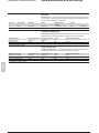
Modbus communication
Contents
Presentation
142
Modbus protocol
143
Configuring the communication interfaces
146
Commissioning and diagnosis
152
Data addresses and encoding
160
Time-tagging of events
173
Access to remote settings
178
Access to remote settings
182
Disturbance recording
195
Reading Sepam identification
197
5
Modbus communication
Presentation
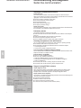
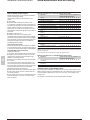
General
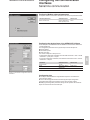
Modbus communication allows Sepam to be connected to a supervisor or any other
device with a master Modbus communication channel.
Sepam is always a slave station.
Sepam is connected to a Modbus communication network via a communication
interface.
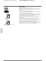
There is a choice of 3 types of communication interface:
b Communication interfaces to connect Sepam to a single serial network:
v ACE949-2, for connection to a 2-wire RS 485 network
v ACE959, for connection to a 4-wire RS 485 network
v ACE937, for connection to a fiber-optic star network.
b Communication interfaces to connect Sepam to two serial networks:
v ACE969TP-2, for connection to:
- one 2-wire RS 485 Modbus S-LAN supervision communication network
- one 2-wire RS 485 E-LAN engineering communication network
v ACE969FO-2, for connection to:
- one fiber-optic Modbus S-LAN supervision communication network
- one 2-wire RS 485 E-LAN engineering communication network.
b Communication interfaces to connect Sepam to an Ethernet network:
v ACE850TP for electrical connection to the network
v ACE850FO for optical connection to the network
Data available
The data available depend on the type of Sepam.
5
Measurement readout
b phase and earth fault currents
b peak demand phase currents
b tripping currents
b cumulative breaking current
b phase-to-phase, phase-to-neutral and residual voltages
b active, reactive and apparent power
b active and reactive energy
b frequency
b temperatures
b thermal capacity used
b starts per hour and inhibit time
b running hours counter
b motor starting current and time
b operating time before overload tripping
b waiting time after tripping
b operating time and number of operations
b circuit breaker charging time.
Program logic data readout
b a table of 144 pre-assigned remote indications (TS) (depends on the type of
Sepam) enables the readout of program logic data status
b readout of the status of 10 logic inputs.
Remote control orders
Writing of 16 impulse-type remote control orders (TC) in either direct mode or SBO
(Select Before Operate) mode via 16 selection bits.
Other functions
b reading of Sepam configuration and identification
b time-tagging of events (synchronization via the network or externally via logic input
I21), time-tagging within a millisecond
b remote reading of Sepam settings
b remote setting of protection units
b remote control of the analog output (with MSA141 option)
b transfer of disturbance recording data.
Modbus protocol
Presentation
Modbus communication
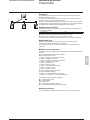
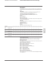
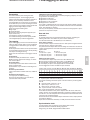
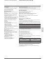
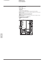
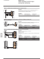
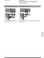
Exchanges
master
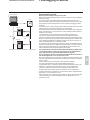
The Modbus protocol exchanges information using a request-reply mechanism
between a master and a slave.
An exchange is always initiated (request sent) by the master. The only action on
the part of a slave is to reply to requests received.
Where the communication network permits, several slaves units can be connected
to a single master. A request contains the slave address (a unique number) to identify
the recipient. Non-addressed slaves disregard the requests received.
DE80334
request
reply
slave
slave
slave
Modbus Protocol Data Unit
Every Modbus request or response frame includes a Modbus PDU (protocol data
unit) made up of 2 fields.
Function code
Data
b function code (1 byte): indicates the type of request (1 to 127)
b data (0 to n bytes): depends on the function code, see below.
If there is no error, the function codes in the reply and in the request are identical.
Modbus data types
Modbus uses 2 types of data: bits and 16-bit words (also called registers).
Each element of data is identified by a 16-bit address.
The most-significant byte in 16-bit words is always sent first, for both data and
addresses.
Modbus functions supported
The Modbus protocol used by Sepam is a compatible sub-group of the RTU Modbus
protocol.
The functions listed below are handled by Sepam:
b basic functions (data access)
v function 1: reading of n output or internal bits
v function 2: reading of n input bits
v function 3: reading of n output or internal words
v function 4: reading of n input words
v function 5: writing of 1 bit
v function 6: writing of 1 word
v function 7: high-speed reading of 8 bits
v function 15: writing of n bits
v function 16: writing of n words.
b communication-management functions:
v function 8: Modbus diagnosis
v function 11: reading of Modbus event counter
v function 43: sub-function 14: reading of identification
The following exception codes are supported:
b 1: unknown function code
b 2: incorrect address
b 3: incorrect data
b 4: not ready (cannot process request)
b 7: not acknowledged (remote reading and setting).
Modbus specification
The full description of the Modbus protocol can be found at www.modbus.org.
5
Modbus protocol
Serial line Modbus
Modbus communication
This description is limited to the Modbus protocol using a serial link in binary mode
(RTU mode).
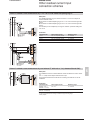
Frames
All the frames exchanged have the same structure, made up of 3 parts.
Slave address
Modbus PDU
Check (CRC16)
b Slave address (1 byte): from 1 to 247 (0 for broadcasting)
b Modbus PDU: as previously described
b Check (2 bytes): CRC16 used to check frame integrity.
The slave addresses in the reply and in the request are identical.
The maximum size of a frame is 256 bytes (255 for Sepam series 40).
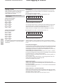
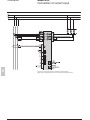
Synchronization of exchanges
Any character that is received after a silence of more than 3.5 characters is
considered as the beginning of a new frame. A minimum silence of 3.5 characters
must always be observed between two frames.
A slave disregards all frames:
b received with a physical error for 1 or more characters (format error, parity error,
etc.)
b with an incorrect CRC16 result
b for which it is not the recipient.
DE80299
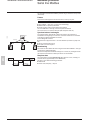
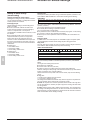
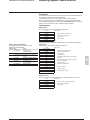
master
broadcasting
Broadcasting
slave
slave
slave
The master can also address all slaves using the conventional address 0. This type
of exchange is called broadcasting.
Slaves do not respond to broadcast messages. As a result, only messages that do
not require the transmission of data by the slaves can be broadcast.
5
DE52312
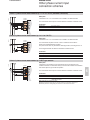
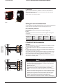
Response time
The communication coupler response time (Tr) is less than 15 ms, including a 3character silence (approximately 3 ms at 9600 bauds).
This time is given with the following parameters:
b 9600 bauds
b format: 8 bits, odd parity, 1 stop bit.
Modbus communication
Modbus protocol
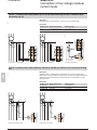
Modbus over TCP/IP
Requests and replies are exchanged as TCP/IP messages over a TCP connection.
The slave address is therefore its IP address.
Frames
The application layer part of a Modbus/TCP frame is made up of 2 fields:
MBAP Header
Modbus PDU
b MBAP (Modbus Application) Header (7 bytes): identifies the frame
b Modbus PDU: as previously described.
Modbus Application header
It contains the following fields:
Field
Length
Description
Transaction
identifier
2 bytes
Identification of a
Modbus request/
response transaction
Protocol identifier 2 bytes
0 = Modbus protocol
Length
2 bytes
Unit identifier
1 byte
Number of following
bytes (including unit
identifier)
In case of gateways,
identifies a remote
slave device
connected on a serial
line. Should be 255 in
other cases.
Request
Response
Field initialized by Field copied by
the client
the server from
the received
request
Field initialized by Field copied by
the client
the server from
the received
request
Field initialized by Field initialized by
the client
the server
Field initialized by Field copied by
the client
the server from
the received
request
5
Modbus communication
Configuring the communication
interfaces
Serial line communication
Access to configuration parameters
PE50619
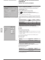
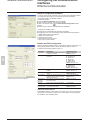
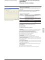
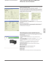
The Sepam communication interfaces are configured using SFT2841 software.
The configuration parameters can be accessed from the Communication
configuration window in SFT2841.
To access this window:
b open the Sepam configuration window in SFT2841
b check the box for ACExxx (communication interface)
b click
: the Communication configuration window appears
b select the type of interface used: ACE949/ACE959/ACE937, ACE969TP or
ACE969FO
b select the Modbus communication protocol.
SFT2841: Sepam Configuration screen.
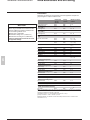
The configuration parameters will vary depending on the communication interface
selected: ACE949/ACE959/ACE937, ACE969TP or ACE969FO. The table below
specifies the parameters to be configured depending on the communication interface
chosen.
Parameters to be configured
Physical layer parameters
ACE949
ACE959
ACE937
b
ACE969TP
b
b
b
Fiber-optic parameters
Modbus advanced parameters
ACE969FO
b
E-LAN parameters
b
b
b
b
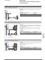
Configuring the physical layer of the Modbus port
PE50620
Asynchronous serial transmission is used with the following character format:
b 1 start bit
b 8 data bits
b 1 stop bit
b parity according to parameter setting.
The number of stop bits is always set at 1.
If a configuration with parity is selected, each character will contain 11 bits: 1 start bit
+ 8 data bits + 1 parity bit + 1 stop bit.
If a no parity configuration is selected, each character will contain 10 bits: 1 start bit
+ 8 data bits + 1 stop bit.
5
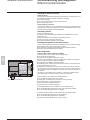
The configuration parameters for the physical layer of the Modbus port are:
b slave number (Sepam address)
b transmission speed
b parity check type.
Parameters
SFT2841: communication configuration window for ACE949.
Authorized values
Default value
Sepam address
1 to 247
1
Speed
4800, 9600, 19200 or
38400 bauds
None, Even or Odd
19200 bauds
Parity
Even
Configuring the ACE969FO-2 fiber-optic port
The configuration for the physical layer of the ACE969FO-2 fiber-optic port is
completed with the following 2 parameters:
b Link idle state: light-on or light-off
b Echo mode: with or without.
Fiber-optic parameters
Link idle state
Echo mode
Authorized values
Default value
Light Off or Light On
Light Off
Yes (fiber-optic ring)
No
or No (fiber-optic star)
Note: in echo mode, the Modbus master will receive the echo of its own request before the
slave's reply. The Modbus master must be able to disregard this echo. Otherwise, it is impossible
to create a Modbus fiber-optic ring.
Modbus communication
Configuring the communication
interfaces
Serial line communication
Configuring Modbus advanced parameters
PE50621
The Sepam remote control mode is selected from the Advanced parameters window.
Advanced parameters
Remote control mode
Authorized values
Default value
Direct or SBO (Select
Before Operate) mode
Direct
SFT2841: Modbus advanced parameters window.
Configuring the physical layer of the ACE969-2 E-LAN port
PE50622
The E-LAN port on the ACE969TP-2 and ACE969FO-2 communication interfaces is
a 2-wire RS 485 port.
The configuration parameters for the physical layer of the E-LAN port are:
b Sepam address
b transmission speed
b parity check type.
The number of stop bits is always set at 1.
If a configuration with parity is selected, each character will contain 11 bits: 1 start bit
+ 8 data bits + 1 parity bit + 1 stop bit.
If a no parity configuration is selected, each character will contain 10 bits: 1 start bit
+ 8 data bits + 1 stop bit.
Parameters
Authorized values
Default value
Sepam address
1 to 247
1
Speed
4800, 9600, 19200 or
38400 bauds
None, Even or Odd
38400 bauds
Parity
Odd
SFT2841: communication configuration window for
ACE969FO.
Configuration tips
b The Sepam address MUST be assigned before Sepam is connected to the
communication network.
b You are also strongly advised to set the other physical layer configuration
parameters before making the connection to the communication network.
b Modifying the configuration parameters during normal operation will not disturb
Sepam but will reset the communication port.
5
Modbus communication
Configuring the communication
interfaces
Ethernet communication
Access to configuration parameters
PE80510
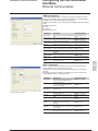
The Sepam communication interfaces must be configured using SFT2841 software.
The configuration parameters can be accessed from the Communication
configuration window in the SFT2841 software.
To access this window:
b open the Sepam configuration window in SFT2841
b check the box for ACExxx (communication interface)
b click on the relevant button
: the Communication configuration window
appears
b select the type of interface used: ACE850TP or ACE850FO.
SFT2841: Sepam configuration screen.
Configuring an ACE850 involves:
b configuring the standard Ethernet parameters (mandatory)
b configuring one or more of the following sets of advanced optional parameters:
v SNMP: Ethernet network management
v SNTP: time synchronization
v IP filtering: access control
v RSTP: Ethernet ring management
v User accounts: access control.
Ethernet and TCP/IP configuration
PE80395
Before configuring the ACE850, obtain a unique static IP address, subnet mask, and
default gateway address from the network administrator. See the section on
IP address and parameter guidelines, page 151.
Parameters
Frame format
Media type
5
IP address
Subnet mask
Default gateway
SFT2841: Ethernet and TCP/IP configuration.
Allow CID file to
override IP
parameters
Keep alive
FTP session
inactivity timeout
Description
Authorized values
Used to select the format for data sent over
an Ethernet connection.
Used to define the physical Ethernet
connection.
Ethernet II, 802.3, Auto
Default: Ethernet II
ACE850TP
b 10T/100Tx Auto
b 10BaseT-HD
b 10BaseT-FD
b 100BaseTX-HD
b 100BaseTX-FD
Default: 10T/100Tx Auto
ACE850FO
b 100BaseFX-HD
b 100BaseFX-FD
Default: 100BaseFX-FD
Used to enter the static IP address of the 0.0.0.0 to 255.255.255.255
ACE850.
Default: 169.254.0.10
Used to enter the subnet mask of your
0.0.0.0 to 255.255.255.255
network.
Default: 255.255.0.0
Used to enter the default gateway (router) 0.0.0.0 to 255.255.255.255
IP address used for wide area network
Default: 0.0.0.0
(WAN) communications.
This parameter is not used for Modbus
Default: not checked
only communication.
Timeout value used to test for session
disconnection.
Timeout value used to force disconnection
of an inactive FTP session
1 to 60 seconds
Default: 30 seconds
30 to 900 seconds
Default: 30 seconds
Duplicate IP address detection
The ACE850 IP address must be unique in the network. If it is not unique, the Status
LED repeats a four blink-pause pattern and a new IP address must be assigned to
the ACE850 or to the conflicting device.
Modbus communication
Configuring the communication
interfaces
Ethernet communication
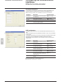
SNMP configuration
PE80396
The ACE850 supports SNMP V1, allowing a network administrator to remotely
access it with an SNMP manager and view the network status and diagnostics in
the MIB2 format (only a subset of MIB2 is implemented).
Additionally, the ACE850 may be configured to send SNMP traps in the following
cases:
b ACE850 start/restart
b Link up
b Link down
b Authentication failure.
Parameters
System Name
System Contact
System Location
SFT2841: SNMP configuration.
Read-only
Community Name
Read-write
Community Name
Enable traps
Traps
Community Name
Manager 1 IP
address
Manager 2 IP
address
Description
Authorized values
This parameter is the same as the Sepam Not modifiable from this
label.
screen.
Name of the administrative contact
String (< 16 characters)
Default: empty string
Location of the Sepam/ACE850
String (< 16 characters)
Default: empty string
SNMP community that has read-only
access to the MIB. Acts as a password.
SNMP community that has read-write
access to the MIB. Acts as a password.
Checking this check box enables SNMP to
send traps.
SNMP community that is used with traps.
String (< 16 characters)
Default: "public"
String (< 16 characters)
Default: "private"
Default: "not checked"
String (< 16 characters)
Default: "public"
IP address of the SNMP manager to which 0.0.0.0 to 255.255.255.255
traps are sent.
Default: 0.0.0.0
IP address of a second SNMP manager to 0.0.0.0 to 255.255.255.255
which traps are sent.
Default: 0.0.0.0
SNTP configuration
PE80397
SNTP is a time synchronization protocol that can be used to synchronize the
Sepam. SNTP is used in mode 3-4 (unicast mode).
b If SNTP is used, the synchronization source for Sepam must be defined as
Ethernet.
b If SNTP is not used, the Sepam synchronization must be ensured by other
means (Modbus frames, synchronization tops).
Parameters
Enable SNTP
Time Zone Offset
Enable Daylight
Saving Time
SFT2841: SNTP configuration.
DST offset
DST starts
DST ends
Primary Server IP
Address
Secondary Server
IP Address
Poll Interval
Description
Authorized values
Enables the time and date of the Sepam to
be set by the Simple Network Time
Protocol (SNTP) server.
Determines the difference between local
time and Coordinated Universal Time
(UTC) (same as GMT).
Enables the use of Daylight Saving Time
(Summer time).
Default: not enabled
Difference between standard time and
Daylight Saving Time.
If enabled, DST starts on the selected
date.
If enabled, DST ends on the selected date.
+ 30 or + 60 minutes
Default: + 60 minutes
Default: last Sunday of
March
Default: last Sunday of
October
0.0.0.0 to 255.255.255.255
Default: 0.0.0.0
The IP address of the SNTP server the
ACE850 contacts to get the time
message.
The IP address of another SNTP server
the ACE850 contacts in case the primary
server is down.
Controls how often the ACE850 contacts
the SNTP server for the correct time.
UTC-12 to UTC+14
Default: UTC
Default: not enabled
0.0.0.0 to 255.255.255.255
Default: 0.0.0.0
1 to 300 minutes
Default: 60 minutes
5
Modbus communication
Configuring the communication
interfaces
Ethernet communication
IP filtering configuration
PE80398
The IP filtering function allows the administrator to specify which Modbus/TCP
clients and which IEC 61850 clients have access to the ACE850 services.
Note: if IP filtering is enabled, access is forbidden to any client not in the filtered list.
Parameters
Enable filtering
IP address
IEC 61850
Modbus
Description
Authorized values
Check this box to activate filtering based
on IP addresses.
The IP address of a client for which
filtering options are defined.
Check this box to grant IEC 61850 access
to the given IP address.
Check this box to grant Modbus/TCP
access to the given IP address.
Default: not enabled
0.0.0.0 to 255.255.255.255
Default: 0.0.0.0
Default: not checked
Default: not checked
SFT2841: IP filtering configuration.
RSTP configuration
PE80399
The RSTP protocol enables the use of redundant Ethernet architectures such as
rings.
It must be enabled each time the ACE850 is included in a loop. It may be disabled
in other cases.
Changing the default settings is normally not required and should be performed with
extreme care as it could jeopardize the stability of the Ethernet network.
If in doubt, it is always possible to revert to the default values using the Default
settings button.
Parameters
5
Enable RSTP
Bridge priority
Hello time
SFT2841: RSTP configuration.
Forward delay time
Description
Authorized values
Check this box to activate the use of the
RSTP protocol.
Priority of the bridge. The bridge with the
lowest priority becomes root.
Amount of time between the transmission
of configuration messages
Default: enabled
Time value to control how fast a port
changes its spanning state when moving
towards the forwarding state
Max age time
Valid duration of configuration message
once sent by the root bridge
Max transmit count
Maximum BPDUs that can be transmitted
by the Port Transmit state machine in any
Hello time. This value limits the maximum
transmission rate.
Cost style
RSTP (32 bits) or STP (16 bits) cost style
selection
Note: RSTP parameters must verify the following relationships:
b 2 x (Forward_delay_time - 1 second) u Max_age_time
b Max_age_time u 2 x (Hello_time + 1 second).
0 - 61440, by steps of 4096
Default: 61440
1 to 10 seconds
Default: 2 seconds
4 to 30 seconds
Default: 21 seconds
6 to 40 seconds
Default: 40 seconds
3 to 100
Default: 32
Default: RSTP
Modbus communication
Configuring the communication
interfaces
Ethernet communication
User accounts configuration
PE80400
ACE850 users are assigned usernames and passwords used to gain access to the
FTP or WEB servers. Each user belongs to a group which determines the user’s
access rights:
b Administrator: read-write access to the FTP server, access to the WEB server
b Operator: read-only access to the FTP server, access to the WEB server
b Guest: no access to the FTP server, access to the WEB server
Up to 4 user accounts can be defined.
Parameters
User control enable
User n
SFT2841: User accounts configuration.
Description
Authorized values
Check this box to enable the configuration Default: enabled
of users account. Currently, the ACE850
will not operate if this box is not checked.
Ensure that this box is always checked.
Check this box to create this user account. Default: user 1 enabled
Uncheck it to delete the account (only the Users 2 to 4 disabled
last account in the list can be deleted).
Name
User name
String (1 to 8 characters)
Password
User password
String (4 to 8 characters)
Group
Group to which the user belongs
Administrator, Operator,
Guest
The following account is always created by default as user 1:
b Name: Admin
b Password: ACE850
b Group: Administrator
IP address and parameter guidelines
IP addresses
Several configuration parameters are IP addresses. These addresses must follow
precise rules which are enforced by SFT2841 and ACE850. These rules are:
b Every IP address is made of 4 fields separated by dots: x . y . z . t
b Each field is a decimal value coded on 8 bits (range [0..255]).
b The first field (x) must be in the range [1..224] but must not be 127.
b Intermediate fields can cover the full range [0..255].
b The last field must not be 0 (range [1..255]).
IP subnet mask
The IP subnet mask is also made of 4 dot separated fields:
b The binary representation of the subnet mask is made of a set of 8 to 30
contiguous ones in the most significant part, followed by a set of contiguous zeroes
(255.0.0.0 to 255.255.255.252).
b For a class A IP address (x y 126), the number of ones in the subnet mask must
be at least 8 (255.y.z.t).
b For a class B IP address (128 y x y 191), the number of ones in the subnet mask
must be at least 16 (255.255.z.t).
b For a class C IP address (192 y x y 223), the number of ones in the subnet mask
must be at least 24 (255.255.255.t).
b The subnet part of the device IP address, obtained when applying the subnet
mask, must not be 0.
IP default gateway
b An IP address of 0.0.0.0 means no gateway.
b If a gateway is defined, it must belong to the same subnet as the device.
5
Modbus communication
Commissioning and diagnosis
Serial line communication
Installing the communication network
Preliminary study
The communication network must first be the subject of a technical study to
determine the following, according to the installation characteristics and constraints
(geography, amount of information processed, etc.):
b the type of medium (electrical or fiber optic)
b the number of Sepam units per network
b the transmission speed
b the ACE interfaces configuration
b the Sepam parameter settings.
Sepam user manual
The communication interfaces must be installed and connected in accordance with
the instructions in the Installation chapter of this manual.
Preliminary checks
The following preliminary checks must be made:
b check the CCA612 cord connection between the ACE interface and the Sepam
base unit
b check the ACE Modbus communication port connection
b check the complete configuration of the ACE
b for the ACE969, check the auxiliary power supply connection.
Checking the operation of the ACE interface
You can use the following to check that an ACE interface is operating correctly:
b the indicator LEDs on the front panel of the ACE
b the information provided by the SFT2841 software connected to Sepam:
v on the Diagnosis screen
v on the Communication configuration screens.
Link activity LED for ACE949-2, ACE959 and ACE937
The link activity LED for ACE949-2, ACE959 and ACE937 interfaces flashes when
Sepam transmission or reception is active.
5
Indicator LEDs on the ACE969
b green "on" LED: ACE969 energized
b red "key" LED: ACE969 interface status
v LED off: ACE969 configured and communication operational
v LED flashing: ACE969 configuration error or ACE969 not configured
v LED on: ACE969 error
b link activity LED: S-LAN Tx flashing, Sepam transmission active
b link activity LED: S-LAN Rx flashing, Sepam reception active.
PE50623
Diagnosis using SFT2841 software
Sepam diagnosis screen
When connected to Sepam, the SFT2841 software informs the operator of the
general Sepam status and of the Sepam communication status in particular.
All Sepam status information appears on the Sepam diagnosis screen.
Sepam communication diagnosis
The operator is provided with the following information to assist with identifying and
resolving communication problems:
b name of the protocol configured
b Modbus interface version number
b number of valid frames received (CPT9)
b number of invalid (mistaken) frames received (CPT2).
SFT2841: Sepam series 40 diagnosis screen.
Modbus communication
Commissioning and diagnosis
Serial line communication
Link activity LED
Modbus diagnosis counters
The ACE interface link activity LEDs are activated by
variations in the signal on the Modbus network. When
the supervisor communicates with Sepam (during
transmission or reception), these LEDs flash.
After wiring, check the information given by the link
activity LEDs when the supervisor operates.
Counter definition
Sepam manages the Modbus diagnosis counters. These are:
b CPT1: Number of valid frames received, whether the slave is involved or not
b CPT2: Number of frames received with a CRC error or physical error (frames with
more than 255 bytes, frames received with at least one parity, overrun, framing or
line-break error)
In the 2-wire RS 485 mode, the counter must not be taken into account
(meaningless).
b CPT3: Number of exception responses generated (even if not transmitted, due to
receipt of a broadcast request)
b CPT4: Number of frames specifically addressed to the station (excluding
broadcasting)
b CPT5: Number of valid broadcast frames received
b CPT6: Not significant
b CPT7: Not significant
b CPT8: Number of frames received with at least one character having a physical
error (parity, overrun, framing or line break)
b CPT9: Number of valid requests received and correctly executed.
Note: Flashing indicates that there is traffic passing to or from
Sepam; it does not mean that the exchanges are valid.
Functional test
If there is any doubt about correct operation of the link:
b run read/write cycles in the test zone
b use Modbus diagnosis function 8 (sub-code 0, echo
mode).
The Modbus frames below, transmitted or received by
a supervisor, are an example of a test performed when
communication is set up.
Test zone
Read
Transmission
01 03 0C00 0002 C75B
Reception
01 03 04 0000 0000 FA33
Write
Transmission
01 10 0C00 0001 02 1234 6727
Reception
01 10 0C00 0001 0299
Read
Transmission
01 03 0C00 0001 875A
Reception
01 03 02 1234 B533
Function 8 - Modbus diagnosis, echo mode
Transmission
01 08 0000 1234 ED7C
Reception
01 08 0000 1234 ED7C
Even in echo mode, Sepam recalculates and checks
the CRC sent by the master:
b if the CRC received is valid, Sepam replies
b if the CRC received is invalid, Sepam does not reply.
Counter reset
The counters are reset to 0:
b when they reach the maximum value FFFFh (65535)
b when they are reset by a Modbus command (function 8)
b when Sepam auxiliary power is lost
b when communication parameters are modified.
Using the counters
Modbus diagnosis counters help to detect and resolve communication problems.
They can be accessed by the dedicated read functions (Modbus protocol functions
8 and 11).
CPT2 and CPT9 counters can be displayed on SFT2841
("Sepam Diagnosis" screen).
An incorrect speed (or parity) increments CPT2.
Non-reception is signaled by the lack of change on CPT9.
Operating anomalies
It is advisable to connect the Sepam units to the Modbus network one by one.
Make sure that the supervisor is sending frames to the relevant Sepam by checking
the activity on the RS 232 - RS 485 converter or the fiber-optic converter if there is
one, and on the ACE module.
RS 485 network
b check the wiring on each ACE module
b check the tightness of the screw terminals on each ACE module
b check the connection of the CCA612 cord linking the ACE module to the Sepam
base unit
b check that polarization is only at one point and that impedance matching is at both
ends of the RS 485 network
b check the auxiliary power supply connection to the ACE969TP-2
b check that the ACE909-2 or ACE919 converter used is connected, powered and
set up correctly.
Fiber-optic network
b check the connections on the ACE module
b check the connection of the CCA612 cord linking the ACE module to the Sepam
base unit
b check the auxiliary power supply connection to the ACE969FO-2
b check that the converter or fiber-optic star used is connected, powered and set up
correctly
b for a fiber-optic ring, check that the Modbus master can handle the echo of its
requests correctly.
In all cases
b check all the ACE configuration parameters on SFT2841
b check the CPT2 and CPT9 diagnostic counters on the SFT2841 ("Sepam
Diagnosis" screen).
5
Commissioning and diagnosis
Ethernet communication
Modbus communication
Installing the Ethernet network
Preliminary study
According to the installation characteristics and constraints, a technical study must
first determine the Ethernet network requirements, including:
b the network topology
b the various subnets (if any) and their interconnections
b the IP addressing scheme
Sepam operating instructions
Communication interfaces must be installed and connected in accordance with the
instructions given in this manual page 244. See also the ACE850 installation guide
delivered with each ACE850, reference BBV35290.
Preliminary checks
Perform the following actions:
b check the CCA614 cord connection between the ACE850 interface and the
Sepam base unit
b check the connection of the ACE850 to the Ethernet network
b check the auxiliary power supply connection
b check the complete configuration of the ACE850.
Checking the operation of the ACE interface
You can use the following to check that an ACE850 interface is operating correctly:
b the indicator LEDs on the front panel of the ACE850
b the information provided by the SFT2841 software connected to Sepam
b the Web pages embedded inside the ACE850.
5
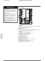
DE80432
Basic diagnostics
ACE850FO
Sepam
F C
S80 S40
P2
P1
100
100
BASE- FX BASE- FX
Tx Rx
ACE850 communication interface.
Tx Rx
1
2
3
4
5
6
Diagnosis using indicator LEDs on the ACE850
1 On/fault indicator. This indicator has the following states:
b Off: the module is not powered
b steady red: the ACE850 is initializing or is faulty
b blinking red: the ACE850 is unable to establish communication with the Sepam
base unit, or the ACE850 is not properly configured
b steady green: the ACE850 is operating correctly
b fast blinking green: indicates a transient state which occurs at startup when IEC
61850 communication is also used
b steady green and blinking red: communication with the base unit has been lost.
This can indicate a normal situation due to a restart of the Sepam after parameters
have been downloaded. The ACE850 automatically resumes normal operation in a
few seconds.
This status can also indicate an error condition, in which case, ACE850 restarts
automatically within 15 seconds and try to re-establish connection.
2 Status indicator. This indicator has the following states:
b Off: the Ethernet communication is not started
b steady green: the Ethernet communication is correctly operating
b three blinks pattern: no logical Ethernet link
b four blinks pattern: duplicate IP address
b six blinks pattern: invalid IP configuration.
3 and 5 Speed indicators. These indicators have the following states:
b Off: the corresponding physical link is down or the port speed is 10Mbps
b On: the corresponding port operates at 100Mbps.
4 and 6 Link/Activity indicators. These indicators have the following states:
b Off: the corresponding physical link is not established
b On: the corresponding physical link is established
b blinking: the indicator blinks with the activity on the link.
Commissioning and diagnosis
Ethernet communication
Modbus communication
SFT2841: Sepam diagnosis screen.
PE80513
PE80512
PE80578
Diagnosis using SFT2841 software
When connected to Sepam, the SFT2841 software informs the operator of the general
Sepam status and of the Sepam communication status in particular.
Sepam status information appears on the Sepam diagnosis screen on which buttons
can be used to obtain detailed status information on each communication channel.
The Sepam diagnosis screen can be used to check that the Sepam base unit and the
ACE850 interface are correctly connected:
Diagnosis screen detail:
ACE850 not or improperly connected.
Diagnosis screen detail:
ACE850 connected properly.
PE80402
The Ethernet diagnosis screen can be used to check:
b the ACE850 module status. The ACE850 status is OK if the ACE850 validates its
configuration.
b the communication ports status
b the current ACE850 IP address. If the current IP address is different from the one
configured, this could mean that the configured address is not valid, unless the
IEC 61850 protocol is also being used.
5
SFT2841: Ethernet diagnosis screen.
Advanced diagnostics using the embedded Web server
The advanced diagnostics feature is only available when it is possible to establish an
Ethernet connection with the ACE850. If not, the basic diagnostics must be used to
solve the problems.
PE80403PE80403
Accessing the ACE850 Web server
1. Start your web browser (Internet explorer 6.0 or higher, Mozilla Firefox for
example).
2. In the address text box, type the address of the ACE850 (169.254.0.10 is the
default), then press Enter.
3. In the login window, type your username and password (default is Admin,
ACE850).
4. From the left side menu, choose the language for the current session.
5. From the menu, click Diagnostics to access the diagnostics menu.
ACE850 home page.
Diagnostics Web pages
There are two general diagnostics pages dealing with Ethernet operation:
b Ethernet global statistics
b Ethernet port statistics
There is also a set of protocol dedicated diagnostic pages:
b Modbus statistics
b IEC 61850 statistics (not covered in this manual)
b SNMP statistics
b SNTP statistics
b RSTP statistics
Diagnostic pages are automatically refreshed every 5 seconds (approximately).
Modbus communication
Commissioning and diagnosis
Ethernet communication
Ethernet TCP/IP statistics
Item
PE80404
Mac address
Description
Unique Ethernet hardware address of the ACE850
Frame type
Value of the frame type configured with SFT2841
TCP/IP parameters
Parameter values configured with SFT2841
Frames received
Total number of received Ethernet frames, regardless of port or
protocol
Total number of transmitted Ethernet frames, regardless of port or
protocol
Button to reset the Ethernet counters
Frames transmitted
Reset Counters button
ACE850 Ethernet TCP/IP statistics.
Ethernet port statistics
PE80407
Item
Selection of the port of which statistics are displayed
Frames transmitted OK
A counter that increments each time a frame is successfully
transmitted.
A counter that increments each time a frame is retransmitted due to
collision detection.
A counter that increments each time a frame cannot be sent
because it has reached the maximum collision status based on the
Truncated Binary Exponential Backoff algorithm.
A counter that increments each time there is a collision because
carrier sense is disabled.
A counter that increments for every transmission error that is not
caused by late, excessive, or carrier sense collisions.
Actual link speed
Collisions
Excessive collisions
Carrier sense errors
ACE850 Ethernet port statistics.
Internal MAC Tx errors
Link speed
Frames received OK
Alignment errors
CRC errors
5
Description
Port P1/P2 buttons
FCS errors
Late collisions
Reset counters button
A counter that increments each time a frame is successfully
received.
A counter that increments each time a received frame has an FCS
error and does not end on an 8-bit frame boundary.
A counter that increments each time a received frame has a CRC
or an alignment error.
A counter that increments each time a received frame has a FCS or
an alignment error.
A counter that increments each time a collision occurs after the slot
time (512 bits starting at the preamble).
Button to reset the port counters
Modbus communication
Commissioning and diagnosis
Ethernet communication
Modbus/TCP server statistics
Item
PE80408
Port status
Description
Modbus port status
Opened TCP connections Number of Modbus clients currently connected
Received messages
Total number of Modbus requests
Transmitted messages
Total number of Modbus responses
Reset counters button
Button to reset the messages counters
Note: the Web interface uses one Modbus connection to operate.
ACE850 Modbus/TCP server statistics.
Modbus/TCP connections statistics
Item
PPE80409
Index
Description
Connection number
Remote IP
IP address of the Modbus client
Remote port
TCP port number on the client side
Local port
TCP port number on the server side
Transmitted messages
Number of Modbus requests for this connection
Received messages
Number of Modbus normal responses for this connection
Sent errors
Number of Modbus exception responses for this connection
Reset counters button
Button to reset the messages counters
ACE850 Modbus/TCP connections statistics.
SNMP statistics
PE80410
Item
ACE850 SNMP statistics.
Description
SNMP agent status
Status of the SNMP agent
Bad Community usages
Number of requests with invalid community
Received messages
Total number of SNMP requests
Transmitted messages
Total number of SNMP responses
Reset counters button
Button to reset the messages counters
5
Modbus communication
Commissioning and diagnosis
Ethernet communication
SNTP statistics
Item
PE80411
SNTP Client status
Description
Value configured for the parameter in SFT2841
Active SNTP server IP address Address of the server currently answering SNTP requests
(0.0.0.0 if no server answer)
Poll interval
Value configured for the parameter in SFT2841
Round trip delay
Total time for SNMP request and response messages
Local offset
Difference between SNTP time and ACE time
Daylight saving time
Value configured for the parameter in SFT2841
Last Successful Time
Synchronization (UTC)
Device Date and Time (UTC)
Last time the ACE850 successfully contacted the SNTP server
(UTC time)
Current time and date of the ACE850 (UTC time)
Device Date and Time (local)
Current time and date of the ACE850 (local time)
ACE850 SNTP statistics.
RSTP bridge statistics
PE80412
Item
5
ACE850 RSTP bridge statistics.
Description
Bridge status
RSTP status of the bridge
Bridge ID
Bridge vector (Bridge priority/Bridge Mac address)
Designated Root ID
Bridge vector of the RSTP root bridge
Designated Root Port
Identifier of the root port (priority/number)
Rootpath cost
Path cost to the root
Total topology changes
Topology change counter (as defined by 802.1D-2004)
Configured hello time
Value of the configured hello time
Learned hello time
Operational value for hello time
Configured forward delay
Reminder of the configured forward delay
Learned forward delay
Operational value for forward delay
Configured max age
Value of the configured max age
Learned max age
Operational value for max age
Modbus communication
Commissioning and diagnosis
Ethernet communication
RSTP port statistics
PE80413
Item
Description
Port P1 / P2 buttons
Selection of the port of which statistics are displayed
Status
RSTP status for the selected port
Role
RSTP role for the selected port
Priority
Port priority
Port path cost
Port contribution to root path cost
Designated port ID
Identifier of the link partner port (priority/number)
Received RSTs
Number of RST BPDUs received (RSTP)
Transmitted RSTs
Number of RST BPDUs sent (RSTP)
Received configure
Number of Configuration BPDUs received (STP)
Transmitted configure
Number of Configuration BPDUs sent (STP)
Received TCNs
Number of Topology change BPDUs received (STP)
Transmitted TCNs
Number of Topology change BPDUs sent (STP)
ACE850 RSTP port statistics.
5
Modbus communication
Data addresses and encoding
Presentation
Data which are similar from the monitoring and control application viewpoint are
grouped together in adjacent address zones:
NOTICE
RISK OF DATA CORRUPTION
When using an ACE850 communication interface
with IEC 61850 communication enabled, do not
use the following address zones:
b Event table 1 (0040-0060),
b Protections settings zone 1 (1E00-1F7C),
b Disturbance recording zone 1 (2200-237C).
Failure to follow these instructions can result
in equipment damage.
Hexadecimal
starting
address
0002
0006
0005
000F
3, 16
3
0040
0041
0040
0060
3, 6, 16
3
0070
0071
0070
0090
3, 6, 16
3
00F0
00F2
00F0
00F2
3, 4, 6, 16
1, 2, 5, 15 (1)
Status
00F1
00F3
0100
00F1
00F3
0112
Measurements
Diagnosis
Phase displacement
Tripping context
Switchgear diagnosis
Application
Test zone
0113
0159
01A0
0250
0290
02CC
0C00
0158
0185
01A9
027F
02A5
02FE
0C0F
3, 4, 6, 16
1, 2, 5, 15 (1)
3, 4
1, 2 (1)
3, 4
3, 4
3, 4
3, 4
3, 4
3
3, 4, 6, 16
1, 2, 5, 15
Synchronization zone
Identification zone
Event table 1
Exchange word
Events (1 to 4)
Event table 2
Exchange word
Events (1 to 4)
Data
Remote control orders
Remote control selection
5
Ending
address
Modbus functions
enabled
Protection settings zone 1
Read settings
1E00
1E7C
3
Read request
1E80
1E80
3, 6, 16
Remote settings
1F00
1F7C
3, 6
Protection settings zone 2
Read settings
2000
207C
3
Read request
2080
2080
3, 6, 16
Remote settings
2100
217C
3, 16
Disturbance recording zone 1
Record selection
2200
2203
3, 16
Identification zone
2204
2271
3
Disturb. rec. exchange word
2300
2300
3, 6, 16
Disturbance recording data
2301
237C
3
Disturbance recording zone 2
Record selection
2400
2403
3, 16
Identification zone
2404
2471
3
Disturb. rec. exchange word
2500
2500
3, 6, 16
Disturbance recording data
2501
257C
3
S-LAN communication monitoring
Time delay
5815
5815
3, 16 (2)
Note: non-addressable zones may reply by an exception message or else supply non-significant
data.
(1) Zones accessible in word mode or bit mode.
The address of bit i (0 y i y F) of address word J is then (J x 16) + i.
Example: 0C00 bit 0 = C000 0C00 bit 7 = C007.
(2) Range allowed: 10 to 65535 x 100 ms (Time delay can be set from 1 to 6553.5 s with
increments of 0.1 s).
Data addresses and encoding
Modbus communication
Data encoding
For all formats
If a measurement overruns the maximum permissible value for the related format,
the value read for the measurement will be the maximum permissible value for the
format.
16NS format
The information is encoded in a 16-bit word, in binary format, absolute value
(unsigned). The 0 bit (b0) is the least significant bit in the word.
16S format signed measurements (temperatures,…)
The information is encoded in a 16-bit word as a complement of 2.
Example:
b 0001 represents +1
b FFFF represents -1.
32NS or 2 x 16NS format
The information is encoded in two 16-bit words, in binary format, unsigned. The first
word is the most significant word.
32S format
The information is encoded as a complement of 2 in 2 words. The first word is the
most significant word:
b 0000, 0001 represents +1
b FFFF, FFFF represents -1.
B format
Rank i bit in the word, with i between 0 and F.
Examples
TS1 to
TS16
TS49 to
TS64
TC1 to
TC16
STC1 to
STC16
F
E
D
C
B
A
9
8
7
6
5
4
3
2
1
0
16
15
14
13
12
11
10
9
8
7
6
5
4
3
2
1
64
63
62
61
60
59
58
57
56
55
54
53
52
51
50
49
16
15
14
13
12
11
10
9
8
7
6
5
4
3
2
1
16
15
14
13
12
11
10
9
8
7
6
5
4
3
2
1
Word address 0101
Bit address 101x
Word address 0104
Bit address 104x
Word address 00F0
Bit address 0F0x
Word address 00F1
Bit address 0F1x
X format: Sepam check-word
This format applies only to the Sepam check-word that may be accessed at the word
address 0100h. This word contains various items of information relating to:
b Sepam operating mode
b time-tagging of events.
Each data item contained in the Sepam check-word may be accessed bit by bit, from
address 1000 for bit 0 to 100F for bit 15.
b bit 15 : event present in event zone 1
b bit 14 : Sepam in “data loss” status in event zone 1
b bit 13 : Sepam not synchronous
b bit 12 : Sepam time not correct
b bit 11 : presence of events in event zone 2
b bit 10 : Sepam in "data loss" status in event zone 2
b bit 9 : major fault in Sepam
b bit 8 : partial fault in Sepam
b bit 7 : setting group A in service
b bit 6 : setting group B in service
b bit 1 : Sepam in local setting mode
b other bits reserved (undetermined values).
Status changes of bits 1, 6, 7, 8, 10, 12, 13 and 14 of this word trigger the sending of
a time-tagged event.
5
Modbus communication
Data addresses and encoding
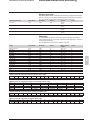
Synchronization zone
The synchronization zone is a table which contains the absolute date and time for
the time-tagging function. Time messages should be written in a single block
containing 4 words, using function 16: write word.
Messages can be read word by word or by groups of words using function 3.
Synchronization zone
Word address
Access
Binary time (year)
0002
Binary time (months + days)
0003
Binary time (hours + minutes)
0004
Binary time (milliseconds)
0005
See "time-tagging of events" chapter for data format.
Modbus function
enabled
3, 16
3
3
3
Read/write
Read
Read
Read
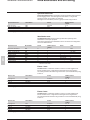
Identification zone
The identification zone contains system-type information pertaining to the
identification of the Sepam equipment.
Some of the information in the identification zone is also found in the configuration
zone at the address 02CCh.
Identification zone
5
Manufacturer identification
Equipment identification
Marking + equipment type
Modbus version
Application version
Sepam check-word
Extension word
Command
Extension address
Word address
0006
0007
0008
0009
000A/B
000C
000D
000E
000F
Access
Modbus function
enabled
R
3
R
3
R
3
R
3
R
3
R
3
R
3
R/W
3/16
R
3
(1) MSB word 2: major index
LSB word 2: minor index.
Format
Value
Not managed
0100
0
Idem 02E2
0
(1)
Not managed
Not managed
Idem 0100
0
Init. to 0
02CC
Events 1 zone
The event zone is a table which contains a maximum of 4 time-tagged events.
Events should be read in a single block containing 33 words using function 3.
The exchange word can be written using functions 6 or 16, and read individually using
function 3.
Events 1 zone
Word address
Access
Exchange word
0040
Event n°1
0041-0048
Event n°2
0049-0050
Event n°3
0051-0058
Event n°4
0059-0060
See "time-tagging of events" chapter for data format.
Read/write
Read
Read
Read
Read
Modbus function
enabled
3, 6, 16
3
3
3
3
Events 2 zone
The event zone is a table which contains a maximum of 4 time-tagged events.
Events should be read in a single block containing 33 words using function 3.
The exchange word can be written using functions 6 or 16 and read individually using
function 3.
Events 2 zone
Word address
Exchange word
0070
Event n°1
0071-0078
Event n°2
0079-0080
Event n°3
0081-0088
Event n°4
0089-0090
See "time-tagging of events" chapter for data format.
Access
Read/write
Read
Read
Read
Read
Modbus function
enabled
3, 6, 16
3
3
3
3
Data addresses and encoding
Modbus communication
Remote control zone
The remote control zone is a table which contains the pre-assigned remote control
bits (TC). The zone may be read or written using the word functions or bit functions.
The use of remote control orders is discussed in detail on page 172.
Remote control orders
TC1-TC16
Word address
00F0
Bit address
0F00
Access
R/W
STC1-STC16
00F1
0F10
R/W
TC17-TC32
00F2
0F20
R/W
STC17-STC32
00F3
0F30
R/W
Function
3/4/6/16
1/2/5/15
3/4/6/16
1/2/5/15
3/4/6/16
1/2/5/15
3/4/6/16
1/2/5/15
Format
B
B
B
B
Status zone
The status zone is a table that contains the Sepam check-word, pre-assigned
remote indication bits (TS), logic inputs, logic equation bits, logic outputs, LEDs and
analog output control word.
The TS assignments are discussed in detail on page 169.
Status
Word address
Bit address
Access
R
R
R
R
R
R
R
R
R
R
-
Modbus function
enabled
3/4 or 1, 2, 7
3/4 or 1, 2
3/4 or 1, 2
3/4 or 1, 2
3/4 or 1, 2
3/4 or 1, 2
3/4 or 1, 2
3/4 or 1, 2
3/4 or 1, 2
3/4 or 1, 2
_
Sepam check-word
TS1-TS16
TS17-TS32
TS33-TS48
TS49-TS64 (reserved)
TS65-TS80
TS81-TS96
TS97-TS112
TS113-TS128
TS129-TS144
Reserved
0100
0101
0102
0103
0104
0105
0106
0107
0108
0109
010A
1000
1010
1020
1030
1040
1050
1060
1070
1080
1090
10A0
Logic inputs
Logic equation bits
010B
010C
10B0
10C0
Format
X
B
B
B
B
B
B
B
B
B
_
R
R
3/4 or 1, 2
3/4 or 1, 2
B
B
B
Logic outputs
010D
10D0
R
3/4 or 1, 2
LEDs
010E
10E0
R
3/4 or 1, 2
B
Analog output
010F
10F0
R/W
3, 6, 16
16S
5
Address word 010B: logic input status (bit address 10B0 to 10BF)
Bit
Inputs
F
-
E
-
D
-
C
-
B
-
A
-
9
I26
8
I25
7
I24
6
I23
5
I22
4
I21
3
I14
2
I13
1
I12
0
I11
Address word 010C: logic equation bit status (bit address 10C0 to 10CF)
Bit
7
Equation V8
6
V7
5
V6
4
V5
3
V4
2
V3
1
V2
0
V1
Bit
F
Equation -
E
-
D
V_FLAGREC
C
V_INHIBCLOSE
B
V_CLOSECB
A
V_TRIPCB
9
V10
8
V9
8
-
7
O14
6
O13
5
O12
4
O11
3
O4
2
O3
1
O2
0
O1
8
L8
7
L7
6
L6
5
L5
4
L4
3
L3
2
L2
1
L1
0
LD
Address word 010D: logic output status (bit address 10D0 to 10DF)
Bit
Output
F
-
E
-
D
-
C
-
B
-
A
-
9
-
Address word 010E: LED status (bit address 10E0 à 10EF)
Bit
F
E
D
C
LED
LD: red LED indicating Sepam unavailable.
B
-
A
-
9
L9
Modbus communication
Data addresses and encoding
Measurement zone x 1
Measurements x 1
5
Word address
Access
Format
Unit
R
Modbus function
enabled
3, 4
Phase current I1 (x 1)
0113
Phase current I2 (x 1)
0114
16NS
0.1 A
R
3, 4
16NS
Phase current I3 (x 1)
0.1 A
0115
R
3, 4
16NS
0.1 A
Residual current I0 Sum (x 1)
Residual current measured (x 1)
0116
0117
R
R
3, 4
3, 4
16NS
16NS
0.1 A
0.1 A
Average phase current Im1 (x 1)
0118
R
3, 4
16NS
0.1 A
Average phase current Im2 (x 1)
0119
R
3, 4
16NS
0.1 A
Average phase current Im3 (x 1)
011A
R
3, 4
16NS
0.1 A
Peak demand phase current IM1 (x 1)
011B
R
3, 4
16NS
0.1 A
Peak demand phase current IM2 (x 1)
011C
R
3, 4
16NS
0.1 A
Peak demand phase current IM3 (x 1)
011D
R
3, 4
16NS
0.1 A
Phase-to-phase voltage U21 (x 1)
011E
R
3, 4
16NS
1V
Phase-to-phase voltage U32 (x 1)
011F
R
3, 4
16NS
1V
Phase-to-phase voltage U13 (x 1)
0120
R
3, 4
16NS
1V
Phase-to-neutral voltage V1 (x 1)
0121
R
3, 4
16NS
1V
Phase-to-neutral voltage V2 (x 1)
0122
R
3, 4
16NS
1V
Phase-to-neutral voltage V3 (x 1)
0123
R
3, 4
16NS
1V
Residual voltage V0 (x 1)
0124
R
3, 4
16NS
1V
Positive sequence voltage Vd (x 1)
0125
R
3, 4
16NS
1V
Negative sequence voltage Vi (x 1)
0126
R
3, 4
16NS
1V
Frequency
0127
R
3, 4
16NS
0.01 Hz
Active power P (x 1)
0128
R
3, 4
16S
1 kW
Reactive power Q (x 1)
0129
R
3, 4
16S
1 kvar
Apparent power S (x 1)
012A
R
3, 4
16S
1 kVA
Peak demand active power Pm (x 1)
012B
R
3, 4
16S
1 kW
Peak demand reactive power Qm (x 1)
012C
R
3, 4
16S
1 kvar
0.01
Power factor cos ϕ (x 100)
012D
R
3, 4
16S
Positive active energy Ea+ (x 1)
012E/012F
R
3, 4
2 x 16NS
100 kW.h
Negative active energy Ea- (x 1)
0130/0131
R
3, 4
2 x 16NS
100 kW.h
Positive reactive energy Er+ (x 1)
0132/0133
R
3, 4
2 x 16NS
100 kvar.h
Negative reactive energy Er- (x 1)
0134/0135
R
3, 4
2 x 16NS
100 kvar.h
Data addresses and encoding
Modbus communication
Measurement zone x 10
Measurements x 10
Word address
Access
Phase current I1 (x 10)
0136
R
Modbus function
enabled
3, 4
Format
Unit
16NS
1A
Phase current I2 (x 10)
0137
R
3, 4
16NS
1A
Phase current I3 (x 10)
0138
R
3, 4
16NS
1A
Residual current I0 Sum (x 10)
0139
R
3, 4
16NS
1A
Residual current measured (x 10)
013A
R
3, 4
16NS
1A
Average phase current Im1 (x 10)
013B
R
3, 4
16NS
1A
Average phase current Im2 (x 10)
013C
R
3, 4
16NS
1A
Average phase current Im3 (x 10)
013D
R
3, 4
16NS
1A
Peak demand phase current IM1 (x 10)
013E
R
3, 4
16NS
1A
Peak demand phase current IM2 (x 10)
013F
R
3, 4
16NS
1A
Peak demand phase current IM3 (x 10)
0140
R
3, 4
16NS
1A
Phase-to-phase voltage U21 (x 10)
0141
R
3, 4
16NS
10 V
Phase-to-phase voltage U32 (x 10)
Phase-to-phase voltage U13 (x 10)
0142
0143
R
R
3, 4
3, 4
16NS
16NS
10 V
10 V
Phase-to-neutral voltage V1 (x 10)
0144
R
3, 4
16NS
10 V
Phase-to-neutral voltage V2 (x 10)
0145
R
3, 4
16NS
10 V
Phase-to-neutral voltage V3 (x 10)
0146
R
3, 4
16NS
10 V
Residual voltage V0 (x 10)
0147
R
3, 4
16NS
10 V
Positive sequence voltage Vd (x 10)
0148
R
3, 4
16NS
10 V
Negative sequence voltage Vi (x 10)
0149
R
3, 4
16NS
10 V
Frequency
014A
R
3, 4
16NS
0.01 Hz
Active power P (x 100)
014B
R
3, 4
16S
100 kW
Reactive power Q (x 100)
014C
R
3, 4
16S
100 kvar
Apparent power S (x 100)
014D
R
3, 4
16S
100 kVA
Peak demand active power Pm (x 100)
014E
R
3, 4
16S
100 kW
Peak demand reactive power Qm (x 100)
014F
R
3, 4
16S
100 kvar
Power factor cos ϕ (x 100)
0150
R
3, 4
16S
0.01
Positive active energy Ea+ (x 1)
0151/0152
R
3, 4
2 x 16NS
100 kW.h
Energie active négative Ea- (x 1)
0153/0154
R
3, 4
2 x 16NS
100 kW.h
Positive reactive energy Er+ (x 1)
0155/0156
R
3, 4
2 x 16NS
100 kvar.h
Negative reactive energy Er- (x 1)
0157/0158
R
3, 4
2 x 16NS
100 kvar.h
Word address
Access
Format
Unit
0159
015A
015B
015C
015D
015E
015F
0160
0161
0162
0163
0164
0165
0166
0167
0168
0169
016A
016B
016C/017B
017C/017D
017E/017F
0180/0181
0182/0183
0184
0185
L
R
R
R
R
R
R
R
R
R
R
R
R
R
R
R
R
R
R
R
R
R
R
R
Modbus function
enabled
3, 4
3, 4
3, 4
3, 4
3, 4
3, 4
3, 4
3, 4
3, 4
3, 4
3, 4
3, 4
3, 4
3, 4
3, 4
3, 4
3, 4
3, 4
3, 4
3, 4
3, 4
3, 4
3, 4
3, 4
16NS
16NS
16NS
16NS
16NS
16NS
16NS
16NS
16NS
16NS
16NS
16NS
16NS
16NS
16NS
16NS
16NS
16S
32NS
32NS
32NS
32NS
16NS
16NS
%
10 A
10 A
10 A
1(kA)2
1
1 ms
0.1 s
1h
%
1 min
1 min
% lb
0.1 s
1A
1 min
1
1 °C (1 °F)
100 kW.h
100 kW.h
100 kvar.h
100 kvar.h
mn
mn
Diagnosis
Diagnosis
Peak demand Ii/Id
Last tripping current Itrip1
Last tripping current Itrip2
Last tripping current Itrip3
Reserved
Cumulative breaking current
Number of operations
Operating time
Charging time
Running hours counter / operation time
Reserved
Thermal capacity used
Time before tripping
Time before closing
Negative sequence / unbalance
Starting time / overload
Starting current / overload
Start inhibit time delay
Number of starts allowed
Temperatures 1 to 16
External positive active energy Ea+ ext
External negative active energy Ea- ext
External positive reactive energy Er+ ext
External negative reactive energy Er- ext
Learnt cooling time constant T2 (49 RMS) thermal rate 1
Learnt cooling time constant T2 (49 RMS) thermal rate 2
5
Modbus communication
Data addresses and encoding
Phase displacement zone
Phase displacement
Phase displacement ϕ0Σ
Phase displacement ϕ0
Phase displacement ϕ1
Phase displacement ϕ2
Phase displacement ϕ3
Word address
Access
01A0/01A1
01A2/01A3
01A4/01A5
01A6/01A7
01A8/01A9
L
L
L
L
L
Modbus function
enabled
3, 4
3, 4
3, 4
3, 4
3, 4
Format
Unit
32NS
32NS
32NS
32NS
32NS
1°
1°
1°
1°
1°
Tripping context zone
Latest tripping context
5
Time-tagging of the context (see "timetagging of events" chapter, page 173)
Tripping current Itrip1
Tripping current Itrip2
Tripping current Itrip3
Residual current I0 Sum
Residual current I0 measured
Phase-to-phase voltage U21
Phase-to-phase voltage U32
Phase-to-phase voltage U13
Phase-to-neutral voltage V1
Phase-to-neutral voltage V2
Phase-to-neutral voltage V3
Residual voltage V0
Positive sequence voltage Vd
Negative sequence voltage Vi
Frequency
Active power P
Reactive power Q
Negative-sequence current Ii
Positive-sequence current Id
Faulty phase (s)
Fault location
Fault resistance
(1) bit 0 = faulty phase 1
bit 1 = faulty phase 2
bit 2 = faulty phase 3
Word address
Modbus
0250/0253
0254
0256
0258
025A
025C
025E
0260
0262
0264
0266
0268
026A
026C
026E
0270
0272
0274
0276
0278
027A
027C
027E
Access
Format
Unit
R
Modbus function
enabled
3
IEC
-
R
R
R
R
R
R
R
R
R
R
R
R
R
R
R
R
R
R
R
R
R
R
3, 4
3, 4
3, 4
3, 4
3, 4
3, 4
3, 4
3, 4
3, 4
3, 4
3, 4
3, 4
3, 4
3, 4
3, 4
3, 4
3, 4
3, 4
3, 4
3, 4
3, 4
3, 4
32NS
32NS
32NS
32NS
32NS
32NS
32NS
32NS
32NS
32NS
32NS
32NS
32NS
32NS
32NS
32S
32S
32NS
32NS
32NS
32NS
32NS
0.1 A
0.1 A
0.1 A
0.1 A
0.1 A
1V
1V
1V
1V
1V
1V
1V
1V
1V
0.01 Hz
1 kW
1 kvar
0.1 A
0.1 A
(1)
m
mΩ
Modbus communication
Data addresses and encoding
Switchgear diagnosis zone
Switchgear diagnosis
Word address
Initial value of cumulative breaking current 0290
Cumulative breaking current (0 < I < 2 In) 0292
Cumulative breaking current (2 In < I < 5 In) 0294
Cumulative breaking current
0296
(5 In < I < 10 In)
Cumulative breaking current
0298
(10 In < I < 40 In)
Cumulative breaking current (I > 40 In)
029A
Cumulative breaking current
029C
Reserved
029E
Number of operations
02A0
(If MES114)
02A2
Operating time
(With MES114)
Charging time
02A4
(With MES114)
Access
Format
Unit
R
R
R
R
Modbus function
enabled
3, 4
3, 4
3, 4
3, 4
32NS
32NS
32NS
32NS
1 kA2
1 kA2
1 kA2
1 kA2
R
3, 4
32NS
1 kA2
R
R
R
3, 4
3, 4
3, 4
32NS
32NS
32NS
1 kA2
1 kA2
1
R
3, 4
32NS
1 ms
R
3, 4
32NS
1 ms
Configuration and application zone
Configuration and application
Word address
Access
Type of application (1)
Name of application (S40, S41, T42…)
02CC
02CD/02D2
R
R
Modbus function
enabled
3
3
Format
Unit
ASCII
12c
ASCII
20c
ASCII
6c
-
-
Sepam marking
02D3/02DC
R
3
Sepam application version
02DD/02DF
R
3
Modbus address (slave number) for
Level 2
Modbus address (slave number) for RHM
Marking + type of equipment (3)
Type of coupler (0 = Modbus)
Communication version
MET148-2 n° 1 module version
02E0
R
3
02E1
02E2
02E3
02E4
02E5/02E7
R
R
R
R
R
3
3
3
3
3
NG
ASCII
6c
ASCII
6c
ASCII
6c
ASCII
6c
ASCII
20c
42 : S41
47 : G40
64 : T50
80 : S53
-
MET148-2 n° 2 module version
02E8/02EA
R
3
MSA141 module version
02EB/02ED
R
3
DSM303 module version
02EE/02F0
R
3
Name of language
02F1/02FA
R
3
Customized languaged version number (2)
English language version number (2)
Boot version number (2)
Extension word (4)
02FB
02FC
02FD
02FE
R
3
R
3
R
3
R
3
(1) 40 : not configured 41 : S40
45 : T42
46 : M41
62 : S51
63 : S52
67 : M40
68 : S54
(2) MSB: major index, LSB: minor index.
(3) 2E2 word: MSB: 11 h (Sepam series 40)
LSB: hardware configuration.
Bit
7
6
5
4
Option MD/MX Extension MET148-2/2 DSM303
Mod.MX 0
z
x
x
Mod.MD 1
z
x
0
x = 1 if option included
y = 1 if option included, exclusive options
z = 1 if extension in 2FE word (4).
-
43 : S42
60 : S43
65 : T52
3
MSA141
x
x
Examples:
I1
U21
Unit = 1 A
Unit = 10 V
44 : T40
61 : S50
66 : S44
2
1
MET148-2/1MES114
x
y
x
y
(4) Bit 0: = 1 if MES114E or MES114F Vac set up.
Accuracy
Measurement accuracy depends on the weight of the
unit; it is equal to the value of the point divided by 2.
5
-
Accuracy = 1/2 = 0.5 A
Accuracy = 10/2 = 5 V
0
MES108
y
y
Modbus communication
Data addresses and encoding
Test zone
The test zone is a 16-word zone that may be accessed via the communication link
by all functions, in both read and write modes, to facilitate communication testing at
the time of commissioning or to test the link.
Test zone
Test
Word address
Bit address
Access
0C00
0C0F
C000-C00F
C0F0-C0FF
Read/write
Read/write
Modbus function
enabled
1, 2, 3, 4, 5, 6, 15, 16
1, 2, 3, 4, 5, 6, 15, 16
Format
None
None
Initialized to 0
Initialized to 0
Protection setting zone
The protection setting zone is an exchange table which is used to read and set the
protection functions. 2 setting zones are available to be used by 2 masters.
Protection setting
Setting read buffer
Setting read request
Remote setting request buffer
See "Protection settings" chapter.
Word address zone 1
1E00/1E7C
1E80
1F00/1F7C
Word address zone 2
2000/207C
2080
2100/217C
Access
R
R/W
R/W
Modbus function enabled
3
3/6/16
3/16
Fault recorder zone
The fault recorder zone is an exchange table which is used to read disturbance
recording records. 2 zones are available to be used by 2 masters.
Disturbance recording
Choice of transfer function
Identification zone
Disturb. rec. exchange zone
Disturbance recording data
See "Disturbance recording" chapter.
5
Word address zone 1
2200/2203
2204/2228
2300
2301/237C
Word address zone 2
2400/2403
2404/2428
2500
2501/257C
Access
R/W
R
R/W
R
Modbus function enabled
3/16
3
3/6/16
3
Modbus communication
Data addresses and encoding
Use of remote indication bits
Sepam provides the communication link with 144 TS.
The remote indications (TS) are pre-assigned to protection and control functions
which depend on the Sepam model.
The TSs may be read using the bit or word functions. Each TS transition is timetagged and stored in the event stack (see “Time-tagging”, page 173).
Address word 0101: TS1 to TS16 (Bit address 1010 to 101F)
TS Application
1
2
3
4
5
6
7
8
9
10
11
12
13
14
15
16
S40 S41 S42 S43 S44 T40
S50 S51 S52 S53 S54 T50
b b b b b b
b b b b b b
b b b b b b
b b b b b b
b b b b b b
b b b b b b
b b b b b b
b b b b b b
b
b
Protection 50/51 unit 1
Protection 50/51 unit 2
Protection 50/51 unit 3
Protection 50/51 unit 4
Protection 50N/51N unit 1
Protection 50N/51N unit 2
Protection 50N/51N unit 3
Protection 50N/51N unit 4
Protection 49 RMS alarm set point
Protection 49 RMS tripping set point
Protection 37
Protection 46 unit 1
b
Protection 46 unit 2
b
Protection 48/51LR/14 (locked rotor)
Protection 48/51LR/14 (rotor locking on
start)
Protection 48/51LR/14 (excessive starting
time)
b
b
b
b
b
b
b
b
b
b
T42 M40 M41 G40
T52
b b
b
b
b b
b
b
b b
b
b
b b
b
b
b b
b
b
b b
b
b
b b
b
b
b b
b
b
b b
b
b
b b
b
b
b
b
b b
b
b
b b
b
b
b
b
b
b
b
b
Address word 0102: TS17 to TS32 (Bit address 1020 to 102F)
TS Application
17
18
19
20
21
22
23
24
25
26
27
28
29
30
31
32
Protection 27D unit 1
Protection 27D unit 2
Protection 27/27S unit 1
Protection 27/27S unit 2
Protection 27R
Protection 59 unit 1
Protection 59 unit 2
Protection 59N unit 1
Protection 59N unit 2
Protection 81H unit 1
Protection 81H unit 2
Protection 81L unit 1
Protection 81L unit 2
Protection 81L unit 3
Protection 81L unit 4
Protection 66
S40 S41 S42 S43 S44 T40 T42 M40 M41 G40
S50 S51 S52 S53 S54 T50 T52
b
b
b
b
b
b
b
b
b
b
b
b
b
b
b
b
b
b
b
b
b
b
b
b
b
b
b
b
b
b
b
b
b
b
b
b
b
b
b
b
b
b
b
b
b
b
b
b
b
b
b
b
b
b
b
b
b
b
b
b
b
b
b
b
b
b
b
b
b
b
b
b
b
b
b
b
b
b
b
b
b
b
b
b
b
b
b
b
b
b
b
b
b
b
b
b
b
b
b
Address word 0103: TS33 to TS48 (Bit address 1030 to 103F)
TS Application
33
34
35
36
37
38
39
40
41
42
43
44
45
46
47
48
Protection 67 unit 1
Protection 67 unit 2
Protection 67N unit 1
Protection 67N unit 2
Protection 47
Protection 32P
Protection 50BF
Protection 32Q
Protection 51V
TC fault
TP Phase fault
TP V0 fault
Reserved
Reserved
Reserved
Reserved
S40 S41 S42
S50 S51 S52
b
b
b
b
b
b
b
b
b
b
b
b
b
b
b
b
b
b
b
b
b
b
b
S43 S44 T40 T42 M40 M41 G40
S53 S54 T50 T52
b
b
b
b
b
b
b
b
b
b
b
b
b
b
b
b
b
b
b
b
b
b
b
b
b
b
b
b
b
b
b
b
b
b
b
b
b
b
b
b
b
b
b
b
b
b
b
5
Modbus communication
Data addresses and encoding
Address word 0104: TS49 to TS64 (Bit address 1040 to 104F)
TS Application
49
Reserved
50
Reserved
51
Reserved
52
Reserved
53
Reserved
54
Reserved
55
Reserved
56
Reserved
57
Reserved
58
Reserved
59
Reserved
60
Reserved
61
Reserved
62
Reserved
63
Reserved
64
Reserved
S40 S41 S42 S43 S44 T40 T42 M40 M41 G40
S50 S51 S52 S53 S54 T50 T52
Address word 0105: TS65 to TS80 (Bit address 1050 to 105F)
TS Application
5
65
S40 S41 S42 S43 S44 T40 T42 M40 M41 G40
S50 S51 S52 S53 S54 T50 T52
Protection 38/49T module 1 alarm set point sensor 1
b
b
b
b
b
66
Protection 38/49T module 1 tripping set point sensor 1
b
b
b
b
b
67
Protection 38/49T module 1 alarm set point sensor 2
b
b
b
b
b
68
Protection 38/49T module 1 tripping set point sensor 2
b
b
b
b
b
69
Protection 38/49T module 1 alarm set point sensor 3
b
b
b
b
b
70
Protection 38/49T module 1 tripping set point sensor 3
b
b
b
b
b
71
Protection 38/49T module 1 alarm set point sensor 4
b
b
b
b
b
72
Protection 38/49T module 1 tripping set point sensor 4
b
b
b
b
b
73
Protection 38/49T module 1 alarm set point sensor 5
b
b
b
b
b
74
Protection 38/49T module 1 tripping set point sensor 5
b
b
b
b
b
75
Protection 38/49T module 1 alarm set point sensor 6
b
b
b
b
b
76
Protection 38/49T module 1 tripping set point sensor 6
b
b
b
b
b
77
Protection 38/49T module 1 alarm set point sensor 7
b
b
b
b
b
78
Protection 38/49T module 1 tripping set point sensor 7
b
b
b
b
b
79
Protection 38/49T module 1 alarm set point sensor 8
b
b
b
b
b
80
Protection 38/49T module 1 tripping set point sensor 8
b
b
b
b
b
Address word 0106: TS81 to TS96 (Bit address 1060 to 106F)
TS Application
81
S40 S41 S42 S43 S44 T40 T42 M40 M41 G40
S50 S51 S52 S53 S54 T50 T52
Protection 38/49T module 2 alarm set point sensor 1
b
b
b
b
b
82
Protection 38/49T module 2 tripping set point sensor 1
b
b
b
b
b
83
Protection 38/49T module 2 alarm set point sensor 2
b
b
b
b
b
84
Protection 38/49T module 2 tripping set point sensor 2
b
b
b
b
b
85
Protection 38/49T module 2 alarm set point sensor 3
b
b
b
b
b
86
Protection 38/49T module 2 tripping set point sensor 3
b
b
b
b
b
87
Protection 38/49T module 2 alarm set point sensor 4
b
b
b
b
b
88
Protection 38/49T module 2 tripping set point sensor 4
b
b
b
b
b
89
Protection 38/49T module 2 alarm set point sensor 5
b
b
b
b
b
90
Protection 38/49T module 2 tripping set point sensor 5
b
b
b
b
b
91
Protection 38/49T module 2 alarm set point sensor 6
b
b
b
b
b
92
Protection 38/49T module 2 tripping set point sensor 6
b
b
b
b
b
93
Protection 38/49T module 2 alarm set point sensor 7
b
b
b
b
b
94
Protection 38/49T module 2 tripping set point sensor 7
b
b
b
b
b
95
Protection 38/49T module 2 alarm set point sensor 8
b
b
b
b
b
96
Protection 38/49T module 2 tripping set point sensor 8
b
b
b
b
b
Modbus Communication
Data addresses and encoding
Address word 0107: TS97 to TS112 (Bit address 1070 to 107F)
TS Application
97
Recloser in service
S40 S41 S42 S43 S44 T40 T42 M40 M41 G40
S50 S51 S52 S53 S54 T50 T52
b
b b
b
b
98
Recloser in progress
b
b
b
b
b
99
Recloser final trip
b
b
b
b
b
100 Recloser successful reclosing
b
b
b
b
b
101 Send blocking input 1
b
b
b
b
b
b
b
b
b
b
102 Remote setting inhibited
b
b
b
b
b
b
b
b
b
b
103 Remote control inhibited
b
b
b
b
b
b
b
b
b
b
104 Sepam not reset after fault
b
b
b
b
b
b
b
b
b
b
105 TC/ position discrepancy
b
b
b
b
b
b
b
b
b
b
106 Matching fault or Trip Circuit Supervision b
b
b
b
b
b
b
b
b
b
107 Disturbance recording stored
b
b
b
b
b
b
b
b
b
b
108 Control fault
b
b
b
b
b
b
b
b
b
b
109 Disturbance recording inhibited
b
b
b
b
b
b
b
b
b
b
110 Thermal protection inhibited
b
b
b
b
b
111 MET148-1 module sensor fault
b
b
b
b
b
112 MET148-2 module sensor fault
b
b
b
b
b
Address word 0108: TS113 to TS128 (Bit address 1080 to 108F)
TS Application
113 Thermistor tripping
S40 S41 S42 S43 S44 T40 T42 M40 M41 G40
S50 S51 S52 S53 S54 T50 T52
b
b
b
b
b
b
b
b
b
b
114 Thermistor alarm
b
b
b
b
b
b
b
b
b
b
115 External tripping 1
b
b
b
b
b
b
b
b
b
b
116 External tripping 2
b
b
b
b
b
b
b
b
b
b
117 External tripping 3
b
b
b
b
b
b
b
b
b
b
118 Buchholz tripping
b
b
119 Thermostat tripping
b
b
120 Pressure tripping
b
b
121 Buchholz alarm
b
b
122 Thermostat alarm
b
b
123 Pressure alarm
b
b
b
b
b
b
b
5
124 SF6 alarm
b
b
b
b
b
125 Recloser ready
b
b
b
b
b
126 Inductive (1)
b
b
b
b
b
b
b
b
b
b
127 Capacitive (1)
b
b
b
b
b
b
b
b
b
b
128 Phase inverse rotation
b
b
b
b
b
b
b
b
b
b
(1) TC17 can be used to inhibit this TS.
Address word 0109: TS129 to TS144 (Bit address 1090 to 109F)
TS Application
129 Send blocking input 2
S40 S41 S42 S43 S44 T40 T42 M40 M41 G40
S50 S51 S52 S53 S54 T50 T52
b
130 Tripping due to protection
b
b
b
b
b
b
b
b
b
b
131 S-LAN communication monitoring
enabled
132 46BC protection (2)
b
b
b
b
b
b
b
b
b
b
b
b
b
b
b
b
b
133 Reserved
134 Reserved
135 Reserved
136 Reserved
137 Reserved
138 Reserved
139 Reserved
140 Reserved
141 Reserved
142 Reserved
143 Reserved
144 Reserved
(2) Only available on S5X and T5X applications.
Modbus communication
Data addresses and encoding
Use of remote control orders
Address word 00F0: TC1 to TC16 (Bit address 0F00 to 0F0F)
Remote control orders are pre-assigned to protection,
control and metering functions.
Remote control orders may be carried out in two
modes:
b direct mode
b confirmed SBO (select before operate) mode.
It is possible to inhibit all the remote control orders via
one logic input assigned to the function "inhibit remote
control", with the exception of the remote control
tripping order TC1 which can be activated at any time.
The parameter setting of the logic input may be done in
two modes:
b inhibition if the input is at 1
b inhibition if the input is at 0 (negative input)
The device tripping and closing and recloser enabling
and disabling remote control orders are acknowledged
if the "CB control" function is confirmed and if the inputs
required for that logic are present on the MES114
(or MES108) optional module.
Direct remote control order
The remote control order is executed when it is written
in the remote control word. The program logic resets it
to zero after the remote control order is acknowledged.
5
Confirmed SBO remote control order
(select before operate)
In this mode, remote control orders involve two steps:
b selection by the master of the order to be sent by
writing the bit in the STC word and checking of the
selection by rereading the word
b execution of the order to be sent by writing the bit in
the TC word.
The remote control order is executed if the bit in the
STC word and the bit in the associated word are set:
the program logic resets the STC bit and TC bits to zero
after the remote control order is acknowledged.
Deselection of the STC bit takes place:
b if the master deselects it by writing in the STC word
b if the master selects (write bit) a bit other than the
one already selected
b if the master sets a bit in the TC word which does not
match the selection. In this case, no remote control
order is executed.
TC
Application
1
Tripping
S40 S41 S42 S43 S44 T40 T42 M40 M41 G40
S50 S51 S52 S53 S54 T50 T52
b b b b b b b b
b
b
2
Closing
b
b
b
b
b
b
b
b
b
b
3
Swtiching to setting group A
b
b
b
b
b
b
b
b
b
b
4
Switching to setting group B
b
b
b
b
b
b
b
b
b
b
Sepam reset
b b b b b b b b
b
b
Peak demand current zero reset (2)
b b b b b b b b
b
b
Inhibit thermal protection
b b b
b
b
Inhibit disturbance recording triggering
b b b b b b b b
b
b
(OPG (1))
b
b
9
Confirm disturbance recording triggering b b b b b b b b
(OPG (1))
10
Manual disturbance recording triggering b b b b b b b b
b
b
(OPG (1))
11
Enable recloser
b b b b b
12
Disable recloser
b b b b b
13
Confirm thermal protection
b b b
b
b
14
Reset undercurrent protection
b
b
15
S-LAN communication monitoring
b b b b b b b b
b
b
activation (3)
16
S-LAN communication monitoring
b b b b b b b b
b
b
inhibition
(1) OPG : French acronym for disturbance recording.
(2) Zero resetting of all the peak demands except the peak demand of the negative and positive
sequence current ratio.
(3) TC15 Remote control order follows the same TC1 inhibition mode.
5
6
7
8
Address word 00F2: TC17 to TC32 (Bit address 0F20 to 0F2F)
TC
17
Application
Inhibit TS126 (Inductive) and TS127
(Capacitive)
18
Confirm TS126 (Inductive) and TS127
(Capacitive)
19-32 Reserved
S40 S41 S42 S43 S44 T40 T42 M40 M41 G40
S50 S51 S52 S53 S54 T50 T52
b b b b b b b b
b
b
b
b
b
b
b
b
b
b
b
b
Remote control of the analog output
The analog output of the MSA141 module may be set up for remote control via the
Modbus communication link (word address 010F). The usable range of the numerical
value transmitted is defined by the "min. value" and "max. value" settings of the
analog output.
This function is not affected by remote control inhibition conditions.
Modbus communication
Time-tagging of events
Presentation
Initialization of the time-tagging function
Each time the communication system is initialized (energizing of Sepam), the events
are generated in the following order:
b appearance of "data loss"
b appearance of "incorrect time"
b appearance of "not synchronous"
b disappearance of "data loss".
The function is initialized with the current values of the remote indication and logic
input status without creating any events related to those data. After the initialization
phase, event detection is activated.
It can only be interrupted by saturation of the internal event storage queue or by the
presence of a major fault in Sepam.
The communication system time-tags the data
processed by Sepam. The time-tagging function
assigns a date and precise time to status changes so
that they can be accurately classified over time.
Time-tagged data are events that can be processed in
the control room by the remote monitoring and control
system using the communication protocol for the data
logging and chronological display functions.
Sepam time-tags the following data:
b logic inputs
b remote indications
b information pertaining to Sepam equipment (see
Sepam check-word).
Time-tagging is carried out systematically.
The remote monitoring and control system provides
a chronological display of the time-tagged data.
Time-tagging
Sepam time-tagging of events uses absolute time (see
section on date and time). When an event is detected,
it is tagged with the absolute time given by Sepam’s
internal clock.
All the Sepam internal clocks must be synchronized so
as to avoid drifts and all be the same, thereby allowing
inter-Sepam chronological sorting.
Sepam has two mechanisms for managing its internal
clock:
b time-setting:
to initialize or modify the absolute time. A special
Modbus message, called "time message", is used to
time-set each Sepam
b synchronization:
to avoid Sepam internal clock drifts and ensure interSepam synchronization.
Synchronization may be carried out according to two
principles:
b internal synchronization:
via the communication network without any additional
wiring
b external synchronization:
via a logic input with additional wiring.
At the time of commissioning, the user sets the
synchronization mode parameter.
Date and time
Presentation
An absolute date and time are generated internally by Sepam, comprising the
following information: Year: Month: Day: Hour: minute: millisecond.
The date and time format is standardized (ref.: IEC 60870-5-4).
Power failure protection
The internal clock of Sepam is saved for 24 hours. After a power outage that lasts for
more than 24 hours, the time must be reset.
The period over which Sepam data and time settings are maintained in the event of
a power outage depends on the ambient temperature and the age of the Sepam unit.
Typical values:
b at 25 °C
b at 40 °C
v 24 hours for 3 years
v 24 hours for 7 years
v 16 hours for 10 years
v 18 hours for 10 years
v 10 hours for 15 years
v 14 hours for 15 years
Resetting the date and time
The internal clock of Sepam may be time-set in three different ways:
b by the remote monitoring and control system, via the Modbus link,
b via the SFT2841 software tool, "General characteristics" screen
b via the display of Sepam units equipped with the advanced UMI.
The time tagged on events is encoded in 8 bytes as follows:
b15 b14 b13 b12 b11 b10 b09 b08 b07 b06 b05 b04
5
b03 b02 b01 b00 word
0
0
0
0
0
0
0
0
0
Y
Y
Y
Y
Y
Y
Y
word 1
0
0
0
0
M
M
M
M
0
0
0
D
D
D
D
D
word 2
0
0
0
H
H
H
H
H
0
0
mn
mn
mn
mn mn mn word 3
ms
ms
ms
ms
ms
ms
ms
ms
ms
ms
ms
ms
ms
ms
ms
ms word 4
Y - 1 byte for years: varies from 0 to 99 years.
The remote monitoring and control system must ensure that the year 00 is greater
than 99.
M - 1 byte for months: varies from 1 to 12.
D - 1 byte for days: varies from 1 to 31.
H - 1 byte for hours: varies from 0 to 23.
mn - 1 byte for minutes: varies from 0 to 59.
ms - 2 bytes for milliseconds: varies from 0 to 59999.
These data are encoded in binary format. Sepam is time-set via the "write word"
function (function 16) at the address 0002 with a mandatory 4-word time message.
The bits set to "0" in the description above correspond to format fields which are not
used in and not managed by Sepam.
Since these bits can be transmitted to Sepam with random values, Sepam performs
the necessary disabling.
Sepam does not check the consistency or validity of the date and time received.
Synchronization clock
A synchronization clock is required to set the Sepam date and time;
Schneider Electric has tested the following equipment:
Gorgy Timing, ref. RT300, equipped with the M540 module.
Modbus communication
Time-tagging of events
Reading of events
Exchange word
The exchange word is used to manage a special protocol to be sure not to lose
events following a communication problem. The event table is numbered for that
purpose.
The exchange word includes two fields:
b most significant byte (MSB) = exchange number (8 bits): 0..255
Sepam provides the master or masters with two event
tables. The master reads the event table and
acknowledges by writing the exchange word.
Sepam updates its event table.
The events sent by Sepam are not sorted
chronologically.
Structure of event table 1:
b exchange word 0040h
b event number 1
0041h ... 0048h
b event number 2
0049h ... 0050h
b event number 3
0051h ... 0058h
b event number 4
0059h ... 0060h
5
Structure of event table 2:
b exchange word 0070h
b event number 1
0071h ... 0078h
b event number 2
0079h ... 0080h
b event number 3
0081h ... 0088h
b event number 4
0089h ... 0090h
The master has to read a block of 33 words starting at
the address 0040h/0070h, or 1 word at the address
0040h/0070h.
b15 b14
b13
b12
b11
b10
b09
b08
Exchange number: 0 .. 255
Description of the MSB of the exchange word.
The exchange number contains a numbering byte which identifies the exchanges.
The exchange number is initialized to zero when Sepam is energized. When it
reaches its maximum value (FFh), it automatically returns to 0.
Sepam numbers the exchanges and the master acknowledges the numbering.
b least significant byte (LSB) = number of events (8 bits): 0..4.
b07 b06
b05
b04
b03
b02
b01
b00
Number of events: 0 .. 4
Description of the LSB of the exchange word.
Sepam indicates the number of significant events in the event table in the least
significant byte of the exchange word. Each non-significant event word is initialized
to zero.
Event table acknowledgment
To inform Sepam that the block read by the master has been correctly received, the
master writes the number of the last exchange made in the "Exchange number" field,
and resets the "Number of events" field of the exchange word to zero. After
acknowledgment, the 4 events in the event table are initialized to zero and the old,
acknowledged events are erased in Sepam.
Until the exchange word written by the master becomes "X,0" (with X = number of
the previous exchange that the master wishes to acknowledge), the exchange word
in the table remains at "X, number of previous events".
Sepam only increments the exchange number when new events are present (X+1,
number of new events).
If the event table is empty, Sepam performs no processing operations when the
master reads the event table or the exchange word.
The data are encoded in binary format.
Clearing an event queue
Writing a value "xxFFh" in the exchange word (any exchange number, event
number = FFh) reinitializes the corresponding event queue (all stored events not yet
transmitted are deleted).
This command leads the reset of the bits 10, 11, 14 and 15 of the control word without
associated event generation.
Sepam in data loss (1) / no data loss (0) status
Sepam has two internal storage queues with a capacity of 64 events. If one of the
queues becomes saturated, i.e. 63 events already present, the "data loss" event is
generated by Sepam in the 64th position.
The detection of events stops and the most recent events are lost.
Modbus communication
Time-tagging of events
Description of event encoding
An event is encoded in 8 words with the following structure:
Most significant byte
Least significant byte
Word 1: type of event
08
00
For remote indications, internal data
logic inputs
Word 2: event address
See bit adresses 1000 to 10BF
Word 3: reserved
00
00
Word 4: falling edge: disappearance or rising edge: appearance
00
00
Falling edge
00
01
Rising edge
Word 5: year
00
0 to 99 (year)
Word 6: month-day
1 to 12 (month)
1 to 31 (day)
Word 7: hours-minutes
0 to 23 (hours)
0 to 59 (minutes)
Word 8: milliseconds
0 to 59999
5
Modbus communication
DE80301
master computer
Synchronization
Sepam accommodates two synchronization modes:
b "internal via the network" synchronization mode by the broadcasting of a "time
message" frame via the communication network. Slave number 0 is used for
broadcasting
b "external" synchronization mode via a logic input.
The synchronization mode is selected at the time of commissioning via SFT2841.
Sepam
GERIN
network
Sepam
Architecture for "internal synchronization" via
the communication network.
5
Time-tagging of events
Internal synchronization via the network mode
The “time message" frame is used for both time-setting and synchronization of
Sepam. In this case, it must be sent regularly at brief intervals (between 10 and
60 seconds) in order for synchronous time to be obtained.
Sepam’s internal clock is reset each time a new time frame is received, and
synchronization is maintained if the difference in synchronism is less than
100 milliseconds.
With internal synchronization via the network, accuracy is linked to the master and
its mastery of time frame transmission in the communication network.
Sepam is synchronized without delay at the end of the receipt of the frame.
Time changes are made by sending a frame to Sepam with the new date and time.
Sepam then switches into a transitional non-synchronous status.
When Sepam is in synchronous status, if no "time message” is received for 200
seconds, the appearance of the "not synchronous" event is triggered.
Time-tagging of events
master computer
Synchronization (cont’d)
DE80302
Modbus communication
clock
Sepam
synchronization
link
network
Sepam
Architecture for "external synchronization" via a logic input.
External synchronization via a logic input mode
Sepam can be synchronized externally by means of a logic input (I21) (the MES114
module is required).
The synchronization pulse is determined by the rising edge of the logic input.
Sepam can adapt to all synchronization pulse periods from 10 to 60 s, by 10 s steps.
The shorter the synchronization period, the more accurate time-tagging of status
changes is.
The first time frame is used to initialize Sepam with the absolute date and time (the
following frames are used for the detection of any time changes).
The synchronization pulse is used to reset Sepam’s internal clock. In the initialization
phase, when Sepam is in "non-synchronous" mode, resetting is allowed, within an
amplitude of ±4 seconds.
In the initialization phase, the resetting process (switching of Sepam into
"synchronous" mode) is based on a measurement of the difference between
Sepam’s current time and the nearest ten second period. This measurement is taken
at the time of the receipt of the synchronization pulse following the initialization time
frame. Resetting is allowed if the difference is less than or equal to 4 seconds, in
which case Sepam switches to "synchronous" mode.
As of that time (after the switching to "synchronous" mode), the resetting process is
based on the measurement of a difference (between Sepam’s current time and the
nearest ten second period at the time of the receipt of a synchronization pulse),
which is adapted to match the synchronization pulse period.
The synchronization pulse period is determined automatically by Sepam when
it is energized, based on the first two pulses received: the synchronization
pulse must therefore be operational before Sepam is energized.
The synchronization function only operates after Sepam has been time-set, i.e.
after the disappearance of the "incorrect time" event.
Any time changes greater than ±4 seconds in amplitude are made by sending a new
time frame. The switch from summer time to winter time (and vice versa) is made in
this way as well.
There is a temporary loss of synchronism when the time is changed.
The external synchronization mode requires additional equipment, a
"synchronization clock " to generate a precise periodic synchronization time pulse.
If Sepam is in "correct time and synchronous" status, and if the difference in
synchronism between the nearest ten second period and the receipt of the
synchronization pulse is greater than the synchronism error for 2 consecutive
synchronization pulses, it switches into non-synchronous status and generates the
appearance of a "not synchronous" event.
Likewise, if Sepam is in "correct time and synchronous" status, the failure to receive
a synchronization pulse for 200 seconds generates the appearance of a "not
synchronous" event.
5
Modbus communication
Access to remote settings
Reading of remote settings
(remote reading)
Request frame
The request is made by the master using a "write word" operation (function 6 or 16)
at the address 1E80h or 2080h of a 1-word frame consisting of the following:
Settings accessible for remote reading
Reading of the settings of all the protection functions
may be accessed remotely in 2 independent zones to
enable operation with 2 masters.
Exchange principle
Remote reading of settings (remote reading) takes
place in two steps:
b first of all, the master indicates the code of the
function for which it wishes to know the settings by
means of a "request frame". The request is
acknowledged, in the Modbus sense of the term, to free
the network
b the master then reads a reply zone to find the
required information by means of a "reply frame".
Each function has its own particular reply zone
contents. The time needed between the request and
the reply is linked to Sepam’s low-priority cycle time
and may vary from a few tens to several hundreds of
milliseconds.
b setting zone 1
v read: 1E00h-1E7Ch
v read request: 1E80h
v remote setting: 1F00h-1F7Ch
b setting zone 2
v read: 2000h -207Ch
v read request: 2080h
v remote setting: 2100h -217Ch
1E80h/2080h
B15 B14 B13 B12 B11 B10 B09 B08 B07 B06 B05 B04 B03 B02 B01 B00
Function code
Unit number
The content of the address 1E80h/2080h may be read using a Modbus "read word"
operation (function 3).
The function code field may have the following values:
b 01h to 99h (BCD encoding) for protection functions.
The unit number field is used as follows:
b for protection functions, it indicates the unit involved, varying from 1 to N, N being
the maximum number of relays available in the Sepam
b when only one unit of a protection function is available, this number field is not
controlled.
Exception replies
In addition to the usual cases, Sepam can send Modbus type 07 exception replies
(not acknowledged) if another remote reading request is being processed.
Reply frame
The reply, sent back by Sepam, fits into a zone with a maximum length of 25 words
at the address 1E00h or 2000h, which comprises the following:
1E00h-1E7Ch/2000h-207Ch
B15 B14 B13 B12 B11 B10 B09 B08 B07 B06 B05 B04 B03 B02 B01 B00
Function code
Unit number
Settings
..............
(special field for each function)
..............
5
This zone is read by a Modbus "read word" operation (function 3) at the address
2000h.
The length of the exchange may concern:
b first word only (validity test)
b maximum size of the zone (125 mots)
b usable size of the zone (determined by the function being addressed).
However, reading must always begin at the first word in the zone (any other address
triggers an exception reply "incorrect address").
The first word in the zone (function code and unit number) may have the following
values:
b xxyy: with
v function code xx different from 00 and FFh
v unit number yy different from FFh.
The settings are available and confirmed. They word is a copy of the "request frame".
The zone contents remain valid until the next request is made.
b FFFFh: the "request frame" has been processed, but the results in the "reply zone"
are not yet available. It is necessary to repeat "reply frame" reading. The other words
are not significant.
b xxFFh: with the function code xx different from 00 and FFh. The read request for
the settings of the designated function is not valid. The function is not included in the
particular Sepam, or remote reading of it is not authorized: refer to the list of functions
which accommodate remote reading of settings.
Modbus communication
NOTICE
RISK OF UNINTENDED OPERATION
b The device must only be configured and set by
qualified personnel, using the results of the
installation protection system study.
b During commissioning of the installation and
following any modification, check that the Sepam
configuration and protection function settings are
consistent with the results of this study.
Failure to follow these instructions can result in
equipment damage.
Access to remote settings
Remote setting
Data that can be remotely set
Writing of the settings of all the protection functions may be accessed remotely.
Exchange principle
Remote setting is allowed for Sepam units.
Remote setting is carried out for a given function unit by unit.
It takes place in two steps:
b first of all, the master indicates the function code and unit number, followed by the
values of all the settings in the "write request frame". The request is acknowledged
to free the network
b the master then reads a reply zone designed for checking that the settings have
been processed. Each function has its own particular reply zone contents.
They are the same as those of the remote reading function reply frame.
To use remote setting, it is necessary to make all the settings for the function
concerned, even if some of them have not changed.
Request frame
The request is made by the master using a "write n words" operation (function 16) at
the address 1F00h or 2100h. The zone to be written contains a maximum of 123
words.
It contains the values of all the settings and consists of the following:
1F00h/2100h
B15 B14 B13 B12 B11 B10 B09 B08 B07 B06 B05 B04 B03 B02 B01 B00
Function code
Unit number
Settings
..............
(special field for each function)
..............
The content of the address 2100h may be read using a "read n words" operation
(function 3).
b the function code field may have the following values:
01h to 99h (BCD encoding) for the list of protection functions F01 to F99
b the unit number field is used as follows:
for protection functions, it indicates the unit involved, varying from 1 to N, N being the
maximum number of units available in the Sepam. It may never be equal to 0.
Exception reply
In addition to the usual cases, le Sepam can send type 07 exception replies (not
acknowledged) if:
b another remote reading or setting request is being processed
b the remote setting function is inhibited.
5
Modbus communication
Access to remote settings
Reply frame
The reply sent back by Sepam is the same as the remote reading reply frame. It fits
into a zone with a maximum length of 125 words at the address 1E00h or 2000h, and
is composed of the effective settings of the function following a semantic check:
1E00h-1E7Ch/2000h-207Ch
B15 B14 B13 B12 B11 B10 B09 B08 B07 B06 B05 B04 B03 B02 B01 B00
Function code
Unit number
Settings
..............
(special field for each function)
..............
5
This zone is read by a "read n words" operation (function 3) at the address 1E00h or
2000h.
The length of the exchange may concern:
b first word only (validity test)
b maximum size of the zone (125 words)
b usable size of the zone (determined by the function being addressed).
However, reading must always begin at the first word in the zone (any other address
triggers an exception reply "incorrect address").
The first word in the zone (function code and unit number) has the same values as
those described for the remote reading reply frame.
b xxyy: with:
v function code xx different from 00 and FFh
v unit number yy different from FFh.
The settings are available and confirmed. The word is a copy of the "request frame".
The zone contents remain valid until the next request is made.
b 0000h: no "request frame has yet been formulated.
This is espcially the case when Sepam is energized.
The other words are not significant.
b FFFFh: the "request frame" has been processed, but the results in the "reply zone"
are not yet available. It is necessary to repeat "reply frame" reading. The other words
are not significant.
b xxFFh: with the function code xx different from 00 and FFh. The read request for
the settings of the designated function is not valid. The function is not included in the
particular Sepam, or access to settings is impossible, in both read and write modes.
Modbus communication
Access to remote settings
Description of settings
Data format
All the settings are transmitted in signed 32-bit integer
format (encoding, as a complement of 2).
Particular setting value:
7FFF FFFFh means that the setting is out of the validity
range.
1 The Enabled or Disabled setting is encoded as
follows:
0 = Disabled, 1 = Enabled
2 The tripping curve setting is encoded as follows:
0 = definite
1 = inverse
2 = long time inverse
3 = very inverse
4 = extremely inverse
5 = ultra inverse
6 = RI
7 = IEC SIT/A
8 = IEC LTI/B
9 = IEC VIT/B
10 = IEC EIT/C
11 = IEEE Mod. inverse
12 = IEEE Very inverse
13 = IEEE Extr. inverse
14 = IAC inverse
15 = IAC very inverse
16 = IAC extr. inverse
3 The timer hold delay curve setting is encoded as
follows:
0 = definite time
1 = IDMT
4 The H2 restraint variable is encoded as follows:
0 = H2 restraint
1 = no H2 restraint
5 The tripping curve setting is:
0 = definite time
1 = IDMT
6 Setting of latching and CB control
0 = No
1 = Yes
7 Tripping curve for negative sequence undercurrent:
0 = definite
7 = IEC SIT/A
8 = IEC LTI/B
9 = IEC VIT/B
10 = IEC EIT/C
11 = IEEE Mod. inverse
12 = IEEE Very inverse
13 = IEEE Extr. inverse
17 = Schneider specific
8 The activation of each of the cycles is encoded as follows:
Correspondence between bit position / protection according to the table below:
Bit
Activation by
0
Instantaneous phase overcurrent, unit 1
1
Time-delayed phase overcurrent, unit 1
2
Instantaneous phase overcurrent, unit 2
3
Time-delayed phase overcurrent, unit 2
4
Instantaneous phase overcurrent, unit 3
5
Time-delayed phase overcurrent, unit 3
6
Instantaneous phase overcurrent, unit 4
7
Time-delayed phase overcurrent, unit 4
8
Instantaneous earth fault, unit 1
9
Time-delayed earth fault, unit 1
10
Instantaneous earth fault, unit 2
11
Time-delayed earth fault, unit 2
12
Instantaneous earth fault, unit 3
13
Time-delayed earth fault, unit 3
14
Instantaneous earth fault, unit 4
15
Time-delayed earth fault, unit 4
16
Instantaneous directional earth fault, unit 1
17
Time-delayed directional earth fault, unit 1
18
19
Instantaneous directional earth fault, unit 2
20
Instantaneous directional phase overcurrent, unit 1
21
Time-delayed directional phase overcurrent, unit 1
Time-delayed directional earth fault, unit 2
22
Instantaneous directional phase overcurrent, unit 2
23
Time-delayed directional phase overcurrent, unit 2
24
V_TRIPCB (logic equation)
The bit status is encoded as follows:
0 = No activation by the protection function
1 = Activation by the protection function.
9 The time delay unit of the CLPU functions is coded the following way:
0 = millisecond
1 = second
2 = minute
5
Modbus communication
Access to remote settings
General settings
Function number: 3002
Setting
1
2
3
4
Data
Rated frequency
Remote setting enabled
Working language
Active group of settings
5
6
7
8
9
10
Setting mode
Phase CT rating
Number of phase CTs
Rated current In
Basic current Ib
Residual current determination mode
11
12
Rated residual current (In0)
Integration period
13
14
15
Reserved
Rated primary voltage Unp
Rated secondary voltage Uns
16
17
VT wiring
Residual voltage mode
18
19
20
21
Type of cubicle
Increment active power
Increment reactive power
Rated secondary voltage Uns
5
Format/Unit
0 = 50 Hz, 1 = 60 Hz
1 = disabled
0 = English, 1 = other
0 = Group A
1 = Group B
3 = Choice by I13
4 = Choice by remote control
0 = TMS, 1 = I/Is
0 = 5 A, 1 = 1 A, 2 = LPCT
0 = 3 CTs, 1 = 2 CTs
A
A
0 = None
1 = 2 A CSH
2 = 20 A CSH
3 = 1 A CT
4 = 5 A CT
5 = ACE990 Range 1
6 = ACE990 Range 2
7 = 5 A CSH
8 = Sensitive 1 A CT
9 = Sensitive 5 A CT
0.1 A
0 = 5 mn, 1 = 10 mn
2 = 15 mn, 3 = 30 mn
4 = 60 mn
V
0 = 100 V, 1 = 110 V
2 = 115 V, 3 = 120 V
4 = 200 V, 5 = 230 V
6 = Numerical value,
see setting 21
0 = 3 V, 1 = 2 U, 2 = 1 U
0 = None 1 = Σ 3 V
2 = external VT — Uns/3
3 = external VT — Uns/3
0 = incomer 1= feeder
0.1 kW.h
0.1 kvar.h
V
Modbus communication
Access to remote settings
Protection settings
They are organized according to increasing ANSI codes.
ANSI 27/27S - Undervoltage
Function number: 10xx
relay 1: xx = 01, relay 2: xx = 02
Setting
1
Data
Latching
Format/Unit
6
2
CB control
3
Activity
4
Reserved
-
5
6
Reserved
Voltage mode
7
8
9
10
11
12
Us (or Vs) set point
Tripping time delay
Reserved
Reserved
Reserved
Reserved
0 = phase-to-neutral,
1 = phase-to-phase
% Unp (or Vnp)
10 ms
-
6
1
ANSI 27D - Positive sequence undervoltage
Function number: 08xx
relay 1: xx = 01, relay 2: xx = 02
Setting
1
Data
Latching
Format/Unit
6
2
CB control
3
Activity
4
Reserved
-
5
6
7
8
9
10
11
Reserved
Vsd set point
Tripping time delay
Reserved
Reserved
Reserved
Reserved
% Unp
10 ms
-
6
1
ANSI 27R - Remanent undervoltage
Function number: 0901
Setting
1
Data
Latching
Format/Unit
2
Reserved
-
3
Activity
4
Reserved
-
5
6
7
8
9
10
11
Reserved
Us set point
Tripping time delay
Reserved
Reserved
Reserved
Reserved
% Unp
10 ms
-
6
1
ANSI 32P - Active overpower
Function number: 2301
Setting
1
Data
Latching
2
CB control
3
Activity
4
Type
5
6
7
8
9
10
11
12
Reserved
Reserved
Ps set point
Tripping time delay
Reserved
Reserved
Reserved
Reserved
Format/Unit
6
6
1
0 = reverse power
1 = overpower
100 W
10 ms
-
5
Modbus communication
Access to remote settings
ANSI 32Q - Reactive overpower
Function number: 2401
Setting
1
Data
Latching
2
CB control
3
Activity
4
Type
5
6
7
8
9
10
11
12
Reserved
Reserved
Qs set point
Tripping time delay
Reserved
Reserved
Reserved
Reserved
Format/Unit
6
6
1
0 = reverse power
1 = overpower
100 var
10 ms
-
ANSI 37 - Phase undercurrent
Function number: 0501
5
Setting
1
Data
Latching
Format/Unit
6
2
CB control
3
Activity
4
Reserved
-
5
6
7
8
9
10
11
Reserved
Is set point
Tripping time delay
Reserved
Reserved
Reserved
Reserved
% Ib
10 ms
-
6
1
ANSI 38/49T - Temperature monitoring
Function number: 15xx
relay 1: xx = 01 to relay 16: xx = 10h
Setting
1
Data
Latching
Format/Unit
6
2
CB control
3
Activity
4
Reserved
-
5
6
7
8
9
10
11
Reserved
Alarm set point
Trip set point
Reserved
Reserved
Reserved
Reserved
°C
°C
-
6
1
Modbus communication
Access to remote settings
ANSI 46 - Negative sequence / unbalance
Function number: 03xx
relay 1: xx = 01, relay 2: xx = 02
Setting
1
Data
Latching
Format/Unit
6
2
CB control
3
Activity
4
Reserved
-
5
6
Reserved
Tripping curve
-
7
8
9
10
11
12
Is set point
Tripping time delay
Reserved
Reserved
Reserved
Reserved
6
1
7
% Ib
10 ms
-
ANSI 46BC - Broken Conductor
Function number: 2801
Setting
1
Data
Latching
Format/Unit
6
2
CB control
3
Activity
4
Reserved
-
5
6
Reserved
Set point
-
7
Tripping time delay
10 ms
6
1
%
ANSI 47 - Negative sequence overvoltage
Function number: 1901
Setting
1
Data
Latching
Format/Unit
6
2
CB control
3
Activity
4
Reserved
-
5
6
7
8
9
10
11
Reserved
Vsi set point
Tripping time delay
Reserved
Reserved
Reserved
Reserved
% Unp
10 ms
-
6
1
ANSI 48/51LR/14 - Locked rotor, excessive starting time
Function number: 0601
Setting
1
Data
Latching
Format/Unit
6
2
CB control
3
Activity
4
Reserved
-
5
6
7
8
9
10
11
12
13
Reserved
Is set point
Excessive starting time delay
Locked rotor time delay
Locked rotor on start time delay
Reserved
Reserved
Reserved
Reserved
% Ib
10 ms
10 ms
10 ms
-
6
1
5
Modbus communication
Access to remote settings
ANSI 49RMS - Thermal overload
Function number: 0401
Setting
1
Data
Latching
2
CB control
6
3
Activity
1
4
Negative sequence factor K
5
6
7
8
9
5
10
11
12
13
14
15
16
17
18
19
20
21
22
23
24
25
26
27
28
29
30
31
Format/Unit
6
0: without
1: low (2.25)
2: average (4.5)
3: high (9)
Current threshold Is (switching from rate 1/rate 2) % Ib
Accounting for ambient temperature
0: no
1: yes
Maximum equipment temperature
°C
Additional settings taken into account (rate 2)
0: no
1: yes
Learnt cooling time constant (T2 learnt) taken into 0: no
account
1: yes
Reserved
Reserved
Rate 1 - heatrise alarm set point
%
Rate 1 - heatrise tripping set point
%
Rate 1 - heating time constant
mn
Rate 1 - cooling time constant
mn
Rate 1 - initial heatrise
%
Reserved
Reserved
Reserved
Reserved
Reserved
Rate 2 - heatrise alarm set point
%
Rate 2 - heatrise tripping set point
%
Rate 2 - heating time constant
mn
Rate 2 - cooling time constant
mn
Rate 2 - initial heatrise
%
Rate 2 - base current for rate 2
0.1 A
Reserved
Reserved
Reserved
Reserved
Modbus communication
Access to remote settings
ANSI 50/51 - Phase overcurrent
Function number: 01xx
relay 1: xx = 01 to relay 4: xx = 04
Setting
1
Data
Latching
2
CB control
3
Activity
4
Confirmation
5
6
7
H2 restraint set point (1)
Reserved
Group A — tripping curve
0 = none,
1 = neg. seq. overvoltage,
2 = undervoltage
%
2
8
9
10
Group A — Is set point
Group A — tripping time delay
Group A — timer hold curve
0.1 A
10 ms
3
11
12
13
14
15
16
Group A — timer hold delay
Group A — H2 restraint
Group A — Iscmin
Reserved
Reserved
Group B — tripping curve
10 ms
1
0.1 A
2
17
18
19
Group B — Is set point
Group B — tripping time delay
Group B — timer hold curve
0.1 A
10 ms
3
20
Group B — timer hold delay
21
Group B — H2 restraint
22
Group B — Iscmin
23
Reserved
24
Reserved
(1) Set point utilized by all the groups.
Format/Unit
6
6
1
10 ms
1
0.1 A
5
ANSI 50BF - Breaker failure
Function number: 2001
Setting
1
Data
Latching
Format/Unit
6
2
Reserved
-
3
Activity
4
Reserved
-
5
6
Reserved
Use close position of circuit breaker
-
7
8
9
10
11
12
Is set point
Tripping time delay
Reserved
Reserved
Reserved
Reserved
0.1 A
10 ms
-
1
6
Modbus communication
Access to remote settings
ANSI 50N/51N - Earth fault
Function number: 02xx
relay 1: xx = 01 to relay 4: xx = 04
5
Setting
1
Data
Latching
Format/Unit
6
2
CB control
3
Activity
4
Type of I0
0 calculated, 1 measured
5
6
7
Reserved
Reserved
Group A — tripping curve
-
8
9
10
Group A — Is0 set point
Group A — tripping time delay
Group A — timer hold curve
0.1 A
10 ms
3
11
12
13
14
15
16
17
Group A — timer hold delay
Group A — H2 restraint
Reserved
Reserved
Reserved
Reserved
Group B — tripping curve
10 ms
0 yes, 1 no
2
18
19
20
Group B — Is0 set point
Group B — tripping time delay
Group B — timer hold curve
0.1 A
10 ms
3
6
1
2
21
Group B — timer hold delay
10 ms
22
23
24
25
26
Group B — H2 restraint
Reserved
Reserved
Reserved
Reserved
0 yes, 1 no
-
ANSI 51V - Voltage-restrained phase overcurrent
Function number: 2501
Setting
1
Data
Latching
Format/Unit
6
2
CB control
3
Activity
4
Reserved
-
5
6
7
8
9
Reserved
Tripping curve
Is set point
Tripping time delay
Timer hold curve
2
0.1 A
10 ms
3
10
11
12
13
14
Timer hold delay
Reserved
Reserved
Reserved
Reserved
10 ms
-
6
1
Modbus communication
Access to remote settings
ANSI 59 - Overvoltage
Function number: 11xx
relay 1: xx = 01, relay 2: xx = 02
Setting
1
Data
Latching
Format/Unit
6
2
CB control
3
Activity
4
Reserved
-
5
6
Reserved
Voltage mode
7
8
9
10
11
12
Us (or Vs) set point
Tripping time delay
Reserved
Reserved
Reserved
Reserved
0 = phase-to-neutral
1 = phase-to-phase
% Unp (or Vnp)
10 ms
-
6
1
ANSI 59N - Neutral voltage displacement
Function number: 12xx
relay 1: xx = 01, relay 2: xx = 02
Setting
1
Data
Latching
Format/Unit
6
2
CB control
3
Activity
4
Reserved
-
5
6
7
8
9
10
11
Reserved
Vs0 set point
Tripping time delay
Reserved
Reserved
Reserved
Reserved
% Unp
10 ms
-
6
1
ANSI 66 - Starts per hour
Function number: 0701
Setting
1
Data
Latching
Format/Unit
6
2
Reserved
-
3
Activity
4
Reserved
-
5
6
7
8
9
10
11
12
13
14
Reserved
Period of time
Total number of starts
Number of consecutive hot starts
Number of consecutive starts
Time delay between starts
Reserved
Reserved
Reserved
Reserved
Hours
1
1
1
Minutes
-
1
5
Modbus communication
Access to remote settings
ANSI 67 - Directional phase overcurrent
Function number: 21xx
relay 1: xx = 01, relay 2: xx = 02
5
Setting
1
Data
Latching
2
CB control
3
Activity
4
Reserved
-
5
6
7
Reserved
Group A — direction
Group A — characteristic angle
8
Group A — tripping logic
9
Group A — tripping curve
0 line, 1 busbar
0 = 30° angle
1 = 45° angle
2 = 60° angle
0 = one out of three
1 = two out of three
2
10
Group A — Is set point
11
12
Group A — tripping time delay
Group A — timer hold curve
13
14
15
16
17
18
19
Group A — timer hold delay
Reserved
Reserved
Reserved
Reserved
Group B — direction
Group B — characteristic angle
20
21
Group B — tripping logic
Group B — tripping curve
Format/Unit
6
6
1
0.1 A
10 ms
3
10 ms
0 line, 1 busbar
0 = 30° angle
1 = 45° angle
2 = 60° angle
0: 1 on 3, 1: 2 on 3
2
22
Group B — Is set point
23
24
Group B — tripping time delay
Group B — timer hold curve
0.1 A
10 ms
3
25
26
27
28
29
Group B — timer hold delay
Reserved
Reserved
Reserved
Reserved
10 ms
-
Modbus communication
Access to remote settings
ANSI 67N/67NC - Directional earth fault
Function number: 22xx
relay 1: xx = 01, relay 2: xx = 02
Setting
1
Data
Latching
2
CB control
3
Activity
4
Type
5
Type of I0 (Sum or Core balance CT)
6
7
8
9
Reserved
Reserved
Group A — direction
Group A — types 1 and 2: characteristic angle
10
Group A — type 3: limit 1
Group A — type 1: sector
11
Group A — type 3: limit 2
Group A — tripping curve
0 line, 1 busbar
0 = -45° angle
1 = 0° angle
2 = 15° angle
3 = 30° angle
4 = 45° angle
5 = 60° angle
6 = 90° angle
0 to 359°
2 = 76° sector
3 = 83° sector
4 = 86° sector
0 to 359°
2
15
Group A — types 1 and 2: Is0 set point
Group A — type 3: Is0 set point
Group A — tripping time delay
Group A — types 1 and 2: Vs0
Group A — type 3: Vs0
Group A — timer hold curve
0.1 A
0.01 A
10 ms
% Unp
0.1 % Unp
3
16
17
18
19
20
21
22
23
24
Group A — timer hold delay
Group A — memory time
Group A — memory voltage
Reserved
Reserved
Reserved
Reserved
Group B — direction
Group B — types 1 and 2: characteristic angle
25
Group B — type 3: limit 1
Group B — type 1: sector
26
Group B — type 3: limit 2
Group B — tripping curve
10 ms
10 ms
% Unp
0 line, 1 busbar
0 = -45° angle
1 = 0° angle
2 = 15° angle
3 = 30° angle
4 = 45° angle
5 = 60° angle
6 = 90° angle
0 to 359°
2 = 76° sector
3 = 83° sector
4 = 86° sector
0 to 359°
2
30
Group B — types 1 and 2: Is0 set point
Group B — type 3: Is0 set point
Group B — tripping time delay
Group B — types 1 and 2: Vs0
Group B — type 3: Vs0
Group B — timer hold curve
0.1 A
0.01 A
10 ms
% Unp
0.1 % Unp
3
31
32
33
34
35
36
37
Group B — timer hold delay
Group B — memory time
Group B — memory voltage
Reserved
Reserved
Reserved
Reserved
10 ms
10 ms
% Unp
-
12
13
14
27
28
29
Format/Unit
6
6
1
0 = projection
1 = directionalized
0 calculated, 1 measured
5
Modbus communication
Access to remote settings
ANSI 79 - Recloser
Function number: 1701
Setting
1
Data
Activity
Format/Unit
1
2
Number of cycles
1 to 4
3
Reclaim time
10 ms
4
Safety time until ready
10 ms
5
Dead time extension
6
7
8
9
Maximum waiting time
Reserved
Reserved
Cycle 1 activation mode
10 ms
8
10
11
12
13
Cycle 1 dead time
Reserved
Reserved
Cycle 2, 3, 4 activation mode
10 ms
8
14
15
16
17
18
Cycle 2 dead time
Cycle 3 dead time
Cycle 4 dead time
Reserved
Reserved
10 ms
10 ms
10 ms
-
6
ANSI 81H - Overfrequency
Function number: 13xx
relay 1: xx = 01, relay 2: xx = 02
5
Setting
1
Data
Latching
Format/Unit
6
2
CB control
3
Activity
4
Reserved
-
5
Reserved
-
6
7
8
9
10
11
12
13
Fs set point
Tripping time delay
Reserved
Vs set point
Reserved
Reserved
Reserved
Reserved
0.1 Hz
10 ms
% Unp
-
6
1
ANSI 81L - Underfrequency
Function number: 14xx
relay 1: xx = 01 to relay 4: xx = 04
Setting
1
Data
Latching
Format/Unit
6
2
CB control
3
Activity
4
Reserved
-
6
1
5
Reserved
-
6
7
8
Fs set point
Tripping time delay
Restraint
9
10
11
12
13
14
Vs set point
Inhibited threshold
Reserved
Reserved
Reserved
Reserved
0.1 Hz
10 ms
0 none
1 on frequency
variation
% Unp
on frequency variation
-
Modbus communication
Access to remote settings
CLPU 50/51 and CLPU 50N/51N protection settings
Function number: 2A01
(1) numerical value, see setting of time delay unit T.
(2) bit 0 : unit 1 group A activation
bit 1 : unit 2 group A activation
bit 2 : unit 3 group A activation
bit 3 : unit 4 group A activation
bit 4 : unit 1 group B activation
bit 5 : unit 2 group B activation
bit 6 : unit 3 group B activation
bit 7 : unit 4 group B activation
Setting
1
2
3
4
5
6
7
Data
Reserved
Reserved
Reserved
Time before activation Tcold
Pick-up threshold CLPUs
Reserved
CLPU 50/51 global action setting
8
9
10
11
12
13
14
15
16
17
18
19
20
21
22
23
24
25
26
27
28
29
30
31
32
33
Activation of ANSI 50/51 protection unit x: OFF or ON
Unit 1 / Group A 50/51: unit of activation time delay T
Unit 1 / Group A 50/51: activation time delay T
Unit 1 / Group A 50/51: multiplying factor M
Unit 2 / Group A 50/51: unit of activation time delay T
Unit 2 / Group A 50/51: activation time delay T
Unit 2 / Group A 50/51: multiplying factor M
Unit 3 / Group A 50/51: unit of activation time delay T
Unit 3 / Group A 50/51: activation time delay T
Unit 3 / Group A 50/51: multiplying factor M
Unit 4 / Group A 50/51: unit of activation time delay T
Unit 4 / Group A 50/51: activation time delay T
Unit 4 / Group A 50/51: multiplying factor M
Unit 1 / Group B 50/51: unit of activation time delay T
Unit 1 / Group B 50/51: activation time delay T
Unit 1 / Group B 50/51: multiplying factor M
Unit 2 / Group B 50/51: unit of activation time delay T
Unit 2 / Group B 50/51: activation time delay T
Unit 2 / Group B 50/51: multiplying factor M
Unit 3 / Group B 50/51: unit of activation time delay T
Unit 3 / Group B 50/51: activation time delay T
Unit 3 / Group B 50/51: multiplying factor M
Unit 4 / Group B 50/51: unit of activation time delay T
Unit 4 / Group B 50/51: activation time delay T
Unit 4 / Group B 50/51: multiplying factor M
CLPU 50N/51N global action setting
34
35
36
37
38
39
40
41
42
43
44
45
46
47
48
49
50
51
52
53
54
55
56
57
58
Activation of ANSI 50N/51N protection unit x: OFF or ON
Unit 1 / Group A 50N/51N: unit of activation time delay T0
Unit 1 / Group A 50N/51N: activation time delay T0
Unit 1 / Group A 50N/51N: multiplying factor M0
Unit 2 / Group A 50N/51N: unit of activation time delay T0
Unit 2 / Group A 50N/51N: activation time delay T0
Unit 2 / Group A 50N/51N: multiplying factor M0
Unit 3 / Group A 50N/51N: unit of activation time delay T0
Unit 3 / Group A 50N/51N: activation time delay T0
Unit 3 / Group A 50N/51N: multiplying factor M0
Unit 4 / Group A 50N/51N: unit of activation time delay T0
Unit 4 / Group A 50N/51N: activation time delay T0
Unit 4 / Group A 50N/51N: multiplying factor M0
Unit 1 / Group B 50N/51N: unit of activation time delay T0
Unit 1 / Group B 50N/51N: activation time delay T0
Unit 1 / Group B 50N/51N: multiplying factor M0
Unit 2 / Group B 50N/51N: unit of activation time delay T0
Unit 2 / Group B 50N/51N: activation time delay T0
Unit 2 / Group B 50N/51N: multiplying factor M0
Unit 3 / Group B 50N/51N: unit of activation time delay T0
Unit 3 / Group B 50N/51N: activation time delay T0
Unit 3 / Group B 50N/51N: multiplying factor M0
Unit 4 / Group B 50N/51N: unit of activation time delay T0
Unit 4 / Group B 50N/51N: activation time delay T0
Unit 4 / Group B 50N/51N: multiplying factor M0
Format/Unit
10 ms
% In
0 = blocking
1 = multiplication
1
9
(2)
(1)
% Is
9
(1)
% Is
9
(1)
% Is
9
(1)
% Is
9
(1)
% Is
9
(1)
% Is
9
(1)
% Is
9
(1)
% Is
0 = blocking
1 = multiplication
1
9
(2)
(1)
% Is0
9
(1)
% Is0
9
(1)
% Is0
9
(1)
% Is0
9
(1)
% Is0
9
(1)
% Is0
9
(1)
% Is0
9
(1)
% Is0
5
Modbus communication
Access to remote settings
Other protection settings
ANSI 21FL - Fault Locator
Function number : 2901
Setting
1
2
Data
Reserved
Reserved
3
Activity
4
Time delay T
Format/Unit
1
Numerical value, see unit
at setting 5
5
Unit of time delay T
0=s
1 = mn
0 = km
6
Location unit (1)
1 = miles
7
Positive sequence resistance of lines (Rdl)
mΩ/km
8
Positive sequence reactance of lines (Xdl)
mΩ/km
9
Zero sequence resistance of lines (R0l)
mΩ/km
10
Zero sequence reactance of lines (X0l)
mΩ/km
11
Positive sequence resistance of cables (Rdc)
mΩ/km
12
Positive sequence reactance of cables (Xdc)
mΩ/km
13
Zero sequence resistance of cables (R0c)
mΩ/km
14
Zero sequence reactance of cables (X0c)
mΩ/km
15
Percentage of cable
%
(1) This parameter is only valid to display the settings 7 to 14 on the advanced UMI and
SFT2841 software.
ANSI 60 - CT supervision
Function number: 2601
Setting
1
5
Data
Reserved
Format/Unit
-
2
Reserved
3
Activity
4
Reserved
-
5
6
7
8
9
10
11
Reserved
Behavior on 46, 51N, 32P, 32Q functions
Tripping time delay
Reserved
Reserved
Reserved
Reserved
0 none, 1 inhibition
10 ms
-
1
ANSI 60FL - VT supervision
Function number: 2701
Setting
1
Data
Reserved
Format/Unit
-
2
Reserved
3
Activity
4
Reserved
-
5
6
7
8
9
-
10
Reserved
Check loss of 3 V/2 U
Test current
Use Vi, Ii criterion
Behavior on 27/27S, 27D, 32P, 32Q,
47, 51V, 59, 59N functions
Behavior on 67 function
11
Behavior on 67N function
12
13
14
15
16
17
18
19
Vi set point
Ii set point
Time delay loss 3 V/ 2 U
Time delay Vi, Ii
Reserved
Reserved
Reserved
Reserved
1
6
6
6
0 none, 1 inhibition
0 non directional,
1 inhibition
0 non directional,
1 inhibition
% Vn
% In
10 ms
10 ms
-
Modbus communication
Disturbance recording
Presentation
Reading the identification zone
Given the volume of data to be transmitted, the master must ensure that there are
data to be recovered and prepare the exchanges when necessary.
The identification zone, described below, is read by the reading of N words starting
at the address 2204h/2404h:
b 2 reserve words forced to 0
b size of record configuration files encoded in 1 word
b size of record data files encoded in 2 words
b number of records encoded in 1 word
b date of record 1 (least recent) encoded in 4 words (see format below)
b date of record 2 encoded in 4 words (see format below)
b ...
b date of record 19 (most recent) encoded in 4 words (see format below)
b 27 reserve words.
All of these data are consecutive.
The disturbance recording function is used to record
analog and logical signals during a time interval.
Sepam can store up to 19 records.
Each record comprises two files:
b configuration file with suffix .CFG
b data file with suffix .DAT.
The data of each record may be transferred via the
Modbus link.
It is possible to transfer 1 to 19 records to a remote
monitoring and control system. A record may be
transferred as many times as possible, until it is
overwritten by a new record.
If a record is made by Sepam while the oldest record is
being transferred, the oldest record is stopped.
If a command (e.g. remote read or remote setting
request) is carried out during the transfer of a
disturbance recording record, the record in not
disturbed.
Time-setting
Each record can be dated.
Time-setting of Sepam is described in the "Timetagging of events" section.
Reading the contents of the different files
Request frame
The master makes the request by writing the date of the record to be transferred
(function 16) in 4 words starting at the address 2200h.
It should be noted that requesting a new record amounts to stopping the transfers
that are in progress. This is not the case for an identification zone transfer request.
2200h/2400h
B15
B14 B13 B12 B11 B10 B09 B08 B07 B06 B05 B04 B03 B02 B01 B00
Transferring records
O
O
O
O
O
O
O
O
Y
Y
Y
Y
Y
Y
Y
Y
Transfer requests are made record by record. A
configuration file and a data file are produced for each
record.
The master sends the commands to:
b find out the characteristics of the records stored in an
identification zone
b read the contents of the different files
b acknowledge each transfer
b reread the identification zone to ensure that the
record still appears in the list of records available.
2 transfer zones are available:
b transfer zone 1
v request frame: 2200h-2203h
v identification zone: starting at 2204h
v reply frame: starting at 2300h
b transfer zone 2
v request frame: 2400h-2403h
v identification zone: starting at 2404h
v reply frame: starting at 2500h.
O
O
O
O
M
M
M
M
O
O
O
D
D
D
D
D
O
O
O
H
H
H
H
H
O
O
mn
mn
mn
mn
mn
mn
ms
ms
ms
ms
ms
ms
ms
ms
ms
ms
ms
ms
ms
ms
ms
ms
Y - 1 byte for years: varies from 0 to 99 years.
The remote monitoring and control system must ensure that the year 00 is later than
99.
M - 1 byte for months: varies from 1 to 12.
D - 1 byte for days: varies from 1 to 31.
H - 1 byte for hours: varies from 0 to 23.
mn - 1 byte for minutes: varies from 0 to 59.
ms - 2 bytes for milliseconds: varies from 0 to 59999.
Reply frame
Reading of each portion of configuration and data file records by a 125-word read
frame (function 3) starting at the address 2300h.
2300h/2500h
B15 B14 B13 B12 B11 B10 B09 B08 B07 B06 B05 B04 B03 B02 B01 B00
Number of usable bytes
in the data zone
Exchange number
..............
Data zone
..............
Reading should always begin with the first word in the address zone (any other
address triggers an exception reply "incorrect address").
The configuration and data files are read in their entirety in Sepam. They are
transferred adjacently.
5
Modbus communication
5
Disturbance recording
If the master requests more exchanges than necessary, the exchange number
remains unchanged and the number of usable bytes is forced to 0. To guarantee data
transfers, it is necessary to allow a response time of about 500 ms between each
read operation at 2300h.
The first word transmitted is an exchange word. The exchange word comprises two
fields:
b the most significant byte contains the exchange number. It is initialized to zero
after an energizing operation. It is incremented by 1 by Sepam each time a transfer
takes place successfully. When it reaches the value FF, it automatically goes back to
zero
b the least significant byte contains the number of usable bytes in the data zone.
It is initialized to zero after an energizing operation and must be different from FFh.
The exchange word may also have the following values:
b xxyy: the number of usable bytes in the data zone yy must be different from FFh
b 0000h: no "read requeste frame" has yet been formulated.
This is especially the case when Sepam is energized.
The other words are not significant.
b FFFFh: the "request frameé has been processed, but the results in the reply zone
are not yet available.
It is necessary to repeat "reply frame" reading.
The other words are not significant.
The words that follow the exchange word make up the data zone.
SInce the configuration and data files are adjacent, a frame may contain the edn of
the configuration and the beginning of the data file of a record.
It is up to the remote monitoring and control system software to reconstruct the files
in accordance with the transmitted number of usable bytes and the size of the files
indicated in the identification zone.
Acknowledging a transfer
To inform Sepam that a record block that it has just read has been received correctly,
the master must write the number of the last exchange that it has carried out in the
"exchange number" field and set the "number of usable bytes in the data zone" of the
exchange word to zero.
Sepam only increments the exchange number if new acquisition bursts are present.
Rereading the identification zone
To ensure that the record has not been modified, during its transfer by a new record,
the master rereads the contents of the identification zone and ensures that the date
of the recovered record is still present.
Modbus communication
Reading Sepam identification
Presentation
The "Read Device Identification" function is used to access in a standardized manner
the information required to clearly identify a device.
The description is made up of a set of objects (ASCII character strings).
Sepam series 40 accepts the "read identification" function (conformity level 02).
For a complete description of the function, go to www.modbus.org. The description
below covers a subset of the function, adapted to Sepam series 40.
Implementation
Request frame
The request frame is made of the following components.
Field
Slave number
43 (2Bh)
14 (0Eh)
01 or 02
00
CRC16
Size (bytes)
1
1
Generic access function code
1
Read device identification
1
Type of read
1
Object number
2
The type of read is used to select a simplified (01) or a standard (02) description.
Sepam series 40 identification
The objects making up the Sepam series 40
identification are listed below.
Number Type
0
VendorName
Value
"Merlin Gerin" or
"Schneider Electric"
1
2
ProductCode
Application EAN13 code
MajorMinorRevision Application version number
(Vx.yy)
3
4
5
VendorURL
ProductName
ModelName
"www.schneider-electric.com"
"Sepam series 40"
Application name
(e.g. "M41 Motor")
6
UserAppName
Sepam marking
Reply frame
The reply frame is made of the following components.:
Field
Slave number
43 (2Bh)
14 (0Eh)
01 or 02
02
00
00
n
0bj1
lg1
txt1
.....
objn
lgn
txtn
CRC16
Size (bytes)
1
1
1
1
1
1
1
1
1
1
lg1
...
1
1
Ign
2
Generic access function code
Read device identification
Type of read
Conformity level
Continuation-frame flag (none for Sepam)
Reserved
Number of objects (according to read type)
Number of first object
Length first object
ASCII string of first object
Number nth object
Length nth object
ASCII string of nth object
Exception frame
If an error occurs during request processing, a special exception frame is sent.
Field
Slave number
171 (ABh)
14 (0Eh)
01 or 03
CRC16
Size (bytes)
1
1
Generic access exception (2Bh + 80h)
1
Read device identification
1
Type of error
2
5
5
Installation
Contents
Safety instructions
Before starting
200
Precautions
201
Equipment identification
Identification of the base unit
Identification of accessories
Sepam series 40
202
202
203
204
Base unit
Dimensions
Assembly
Connection
Connection of current input
Other phase current input connection schemes
Other residual current input connection schemes
Connection of low voltage residual current inputs
Connections of input voltage
Connection of low voltage phase voltage inputs
206
206
207
208
210
211
212
214
216
217
1 A/5 A current transformers
218
Voltage transformers
220
LPCT type current sensors
221
CSH120 and CSH200 Core balance CTs
224
CSH30 interposing ring CT
226
ACE990 Core balance CT interface
228
MES114 modules
230
Optional remote modules
Connection
233
MET148-2 Temperature sensor module
234
MSA141 Analog output module
236
DSM303 Remote advanced UMI module
238
Communication accessory selection guide
240
Connection of communication interfaces
Connection cords
Characteristics of communication networks
241
241
242
ACE949-2 2-wire RS 485 network interface
243
ACE959 4-wire RS 485 network interface
244
ACE937 fiber optic interface
245
ACE969TP-2 and ACE969FO-2 Multi-protocol interfaces
Description
Connection
246
248
249
ACE850TP and ACE850FO Multi-protocol interfaces
Description
Connection
252
254
255
ACE909-2 RS 232/RS 485 converter
258
ACE919CA and ACE919CC RS 485/RS 485 converters
260
ECI850 IEC 61850 Sepam server
262
6
Installation
Safety instructions
Before starting
This page contains important safety instructions that must be followed precisely
before attempting to install, repair, service or maintain electrical equipment. Carefully
read and follow the safety instructions described below.
DANGER
HAZARD OF ELECTRIC SHOCK, ELECTRIC ARC, BURNS OR
EXPLOSION
b Only qualified personnel should install this equipment. Such work should be
performed only after reading this entire set of instructions.
b NEVER work alone.
b Turn off all power supplying this equipment before working on or inside it.
b Always use a properly rated voltage sensing device to confirm that all power
is off.
b Before performing visual inspections, tests, or maintenance on this
equipment, disconnect all sources of electric power. Assume that all circuits
are live until they have been completely de-energized, tested and tagged. Pay
particular attention to the design of the power system. Consider all sources of
power, including the possibility of backfeeding.
b Beware of potential hazards, wear personal protective equipment, carefully
inspect the work area for tools and objects that may have been left inside the
equipment.
b The successful operation of this equipment depends upon proper handling,
installation, and operation. Neglecting fundamental installation requirements
can lead to personal injury as well as damage to electrical equipment or other
property.
b Handling this product requires relevant expertise in the field of protection of
electrical networks. Only competent people who have this expertise are
allowed to configure and set up this product.
b Before performing Dielectric (Hi-Pot) or Megger testing on any equipment in
which the relay is installed, disconnect all input and output wires to the relay.
High voltage testing can damage electronic components contained in the
Sepam unit.
Failure to follow these instructions will result in death or serious injury.
6
Installation
Precautions
We recommend that you follow the
instructions given in this document for quick,
correct installation of your Sepam unit:
b Equipment identification
b Assembly
b Connection of inputs, current, voltage and
sensors
b Connection of power supply
b Checking prior to commissioning
Transport, handing and storage
Sepam in its original packaging
Transport:
Sepam can be shipped to any destination by all usual means of transport without
taking any additional precautions.
1
Handling:
Sepam can be handled without any particular care and can even withstand being
dropped by a person standing at floor-level.
Storage:
Sepam can be stored in its original packaging, in an appropriate location for several
years:
b Temperature between -25°C and +70°C (between -13°F and +158°F)
b Humidity y 90%.
Periodic, yearly checking of the environment and the packaging condition is
recommended.
Energize the Sepam for 1 hour:
b every 5 years for a storage temperature < 30 ° C (86 ° F)
b every 3 years for a storage temperature u 30 ° C (86 ° F)
b every 2 years for a storage temperature u 50 ° C (122 ° F)
Once Sepam has been unpacked, it should be energized as soon as possible.
Sepam installed in a cubicle
Transport:
Sepam can be transported by all usual means of transport in the customary
conditions used for cubicles. Storage conditions should be taken into consideration
for a long period of transport.
Handling:
Should the Sepam fall out of a cubicle, check its condition by visual inspection and
energizing.
Storage:
Keep the cubicle protection packing for as long as possible. Sepam, like all electronic
units, should not be stored in a damp environment for more than a month. Sepam
should be energized as quickly as possible. If this is not possible, the cubicle
reheating system should be activated.
Environment of the installed Sepam
Operation in a damp environment
The temperature/relative humidity factors must be compatible with the unit’s
environmental withstand characteristics.
If the use conditions are outside the normal zone, special arrangements should be
made before commissioning, such as air conditioning of the premises.
Operation in a polluted atmosphere
A contaminated industrial atmosphere (such as the presence of chlorine, hydrofluoric
acid, sulfur, solvents, etc.) can cause corrosion of the electronic components, in
which case environmental control arrangements should be made (such as
pressurized premises with filtered air, etc.) before commissioning.
The effect of corrosion on Sepam has been tested according to the
IEC 60068-2-60 and EIA 364-65A (See "Environmental Characteristic", page 18).
6
Installation
Equipment identification
Identification of the base unit
Identification of the base unit
Each Sepam comes in a single package which contains the base unit and 2
connectors:
b 1 x 20-pin connector (CCA620 or CCA622)
b 1 x 6-pin connector (CCA626 or CCA627)
The other optional accessories such as modules, current input connectors
or voltage and cords are supplied in separate packages.
To identify a Sepam, check the 2 labels on the right side panel of the base unit
describing the product’s functional and hardware features.
DE80987
b Hardware reference and designation label
User Machine Interface
model
59604
10480001
Series 40/advanced UMI/24-250V
Séries 40/IHM avancée/24-250V
S10MD
59604+01+10480001+C99
Test PASS: 11/30/2010
Operator: C99
DE80988
b Software reference and designation label
S42
S42
series 40
Type of application
Working language
59682
59615
}
6
Additional information
(not given systematically)
Equipment identification
Identification of accessories
Identification of accessories
The accessories such as optional modules, current or voltage connectors and
connection cords come in separate packages, which are identified by labels.
b Example of MES114 module identification label:
Part number
DE80234
Installation
Commercial reference
6
Installation
Equipment identification
Sepam series 40
List of Sepam series 40 references
Reference
59600
59604
59608
Description
Base unit with basic UMI, 24-250 V DC and 100-240 V AC power supply
Base unit with advanced UMI, 24-250 V DC and 100-240 V AC power supply
DSM303, remote advanced UMI module
59615
59616
Working language English/French
Working language English/Spanish
59629
59630
59631
CCA634 connector for 1 A/5 A CT + I0 current sensors
CCA630 connector for 1 A/5 A CT current sensors
CCA670 connector for LPCT current sensors
59634
59635
59636
59638
59639
CSH30 interposing ring CT for I0 input
CSH120 residual current sensor, diameter 120 mm (4.75 in)
CSH200 residual current sensor, diameter 200 mm (7.87 in)
ECI850 IEC 61850 Sepam server with PRI voltage surge arrester
AMT852 lead sealing accessory
59641
59642
59643
59644
MET148-2 8-temperature sensor module
ACE949-2 2-wire RS 485 network interface
ACE959 4-wire RS 485 network interface
ACE937 optical fiber interface
59646
59647
59648
59649
59650
59651
59652
MES114 10 input + 4 output module/24-250 V DC (1)
MSA141 1 analog output module
ACE909-2 RS 485/RS 232 converter
ACE919CA RS 485/RS 485 interface (AC power supply)
ACE919CC RS 485/RS 485 interface (DC power supply)
MES114E 10 input + 4 output module/110-125 V DC and V AC
MES114F 10 input + 4 output module/220-250 V DC and V AC
TCSEAK0100
Ethernet configuration kit for ECI850
(1) Reference 59645 "MES108 module 4I/4O" cancelled and replaced by 59646.
6
Installation
Equipment identification
Sepam series 40
List of Sepam series 40 references
59656
59657
59658
59664
CCA626 6-pin screw type connector
CCA627 6-pin ring lug connector
ACE850TP RJ45 Ethernet multi-protocol interface
(IEC 61850, Modbus TCP/IP)
ACE850FO fiber-optic Ethernet multi-protocol interface
(IEC 61850, Modbus TCP/IP)
CCA770 remote module connection cord, L = 0.6 m (2 ft)
CCA772 remote module connection cord, L = 2 m (6.6 ft)
CCA774 remote module connection cord, L = 4 m (13.1 ft)
CCA612 communication interface communication cord (except ACE850),
L = 3 m (9.8 ft)
CCA783 PC RS 232 port connection cord
59666
59667
59668
59669
59670
59671
59672
CCA613 LPCT test plug
ACE917 LPCT injection adapter
CCA620 20-pin screw type connector
CCA622 20-pin ring lug connector
AMT840 mounting plate
CCA784 PC USB port connection cord
ACE990 core balance CT interface for I0 input
59676
Kit 2640 2 sets of spare connectors for MES114
59679
SFT2841 CD-ROM with SFT2841 and SFT2826 software, without CCA783
cord
Substation application type S40
Substation application type S41
Substation application type S42
Transformer application type T40
Transformer application type T42
Motor application type M41
Generator application type G40
Substation application type S43
Substation application type S44
Motor application type M40
59659
59660
59661
59662
59663
59680
59681
59682
59683
59684
59685
59686
59687
59688
59689
59723
59724
59726
59751
59754
ACE969TP-2 2-wire RS 485 multi-protocol interface
(Modbus, DNP3 or IEC 60870-5-103) (1)
ACE969FO-2 fiber-optic multi-protocol interface
(Modbus, DNP3 or IEC 60870-5-103) (1)
CD SFT850 CD-ROM with IEC 61850 configuration software
CCA614 ACE850 communication interface connection cord,
L = 3 m (9.8 ft)
TCP/IP firmware option (mandatory for using ACE850 multi-protocol
communication interfaces with Sepam series 40, Sepam series 60 and
Sepam series 80).
59780
Substation application type S50
59781
Substation application type S51
59782
Substation application type S52
59783
Substation application type S53
59784
Transformer application type T50
59785
Transformer application type T52
59786
Substation application type S54
(1) Reference 59720 "ACE969TP" cancelled and replaced by 59723, reference 59721
"ACE969FO" cancelled and replaced by 59724.
6
Base unit
Dimensions
Installation
mm
DE80042
mm
in
DE80114
DE80030
Dimensions
mm
in
Mounting
clip
1.58
in
6.3
(2)
3.85
2.04
8.8
7.71
(1)
8.8
1.22
6.93
6.92
Front view of Sepam.
1.58
(2)
1.58
3.86
Sepam with advanced UMI and MES114,
flush-mounted in front panel.
(1)
(1) With basic UMI: 23 mm (0.91 in).
(2) With CCA634: 105 mm (4.13 in).
1.22
Sepam with advanced UMI and MES114,
flush-mounted in front panel.
Clearance for Sepam assembly
and wiring.
Cut-out
Cut-out accuracy must be complied with to ensure good withstand.
HAZARD OF CUTS
Trim the edges of the cut-out plates to remove
any jagged edges.
For mounting plate
3.17 mm (0.125 inch) thick
mm
in
DE80044
CAUTION
DE80028
For mounting plate between 1.5 mm
(0.059 in) and 3 mm (0.12 in) thick
mm
in
Failure to follow these instructions can
result in serious injury.
6
7.95
7.95
2.91
0.47
0.08
6.38
6.38
Used to mount Sepam with basic UMI at the back of the compartment with access to
the connectors on the rear panel.
Mounting associated with the use of the remote advanced UMI (DSM303).
mm
in
0.25
1.58
1.58
7.95
1.58
mm
DE80082
DE80029
Assembly with AMT840 mounting plate
in
9.05
(1)
4.84
1.58
6.38
1.58
0.60
8.5
9.23
AMT840 mounting plate.
0.4
Sepam with basic UMI and MES114, mounted with AMT840 plate.
Mounting plate thickness: 2 mm (0.079 in).
(1) With CCA634: 130 mm (5.12 In).
Base unit
Assembly
Installation
The Sepam is simply flush-mounted and secured by its clips. No additional screw
type fastening is required.
HAZARD OF ELECTRIC SHOCK, ELECTRIC
ARC OR BURNS
b Only qualified personnel should install this
equipment. Such work should be performed only
after reading this entire set of instructions.
b NEVER work alone.
b Turn off all power supplying this equipment
before working on or inside it. Consider all
sources of power, including the possibility of
backfeeding.
b Always use a properly rated voltage sensing
device to confirm that all power is off.
DE51143
DANGER
Failure to follow these instructions will result
in death or serious injury.
1 Present the product as indicated, making sure the metal plate is correctly entered
in the groove at the bottom.
2 Tilt the product and press on the top part to clamp it with the clips.
6
Installation
Base unit
Connection
Sepam components
DE52161
b base unit 1
v A base unit connector:
- power supply
- output relay
- CSH30, 120, 200 or ACE990 input.
Screw-type connector shown (CCA620), or ring lug connector (CCA622)
v B 1/5 CT A current input connector (CCA630 or CCA634) or LPCT current input
connector (CCA670)
v C communication module link connection (white)
v D remote inter-module link connection (black)
v E voltage input connection, screw-type connector shown (CCA626) or ring lug
connector (CCA627)
b optional input/output module 2 (MES114)
v L M MES114 module connectors
v K MES114 module connector.
6
Installation
Base unit
Connection
Connection of the base unit
The Sepam connections are made to the removable connectors located on the rear
panel. All the connectors are screw-lockable.
NOTICE
LOSS OF PROTECTION OR RISK OF
NUISANCE TRIPPING
If the Sepam is no longer supplied with power or
is in fail-safe position, the protection functions
are no longer active and all the Sepam output
relays are dropped out. Check that this operating
mode and the watchdog relay wiring are
compatible with your installation.
Failure to follow these instructions can result
in equipment damage and unwanted
shutdown of the electrical installation.
DANGER
HAZARD OF ELECTRIC SHOCK, ELECTRIC ARC OR BURNS
b Only qualified personnel should install this equipment. Such work should be
performed only after reading this entire set of instructions.
b NEVER work alone.
b Turn off all power supplying this equipment before working on or inside it.
Consider all sources of power, including the possibility of backfeeding.
b Always use a properly rated voltage sensing device to confirm that all power
is off.
b Start by connecting the device to the protective ground and to the functional
ground.
b Screw tight all terminals, even those not in use.
DE51131
Failure to follow these instructions will result in death or serious injury.
Wiring of connectors CCA620 and CCA626:
b Without fitting:
v 1 wire with maximum cross-section of 0.2 to 2.5 mm2 (u AWG 24-12) or 2 wires
with maximum cross-section of 0.2 to 1 mm2 (u AWG 24-16)
v Stripped length: 8 to 10 mm (0.31 to 0.39 in)
b With fitting:
v Recommended wiring with Telemecanique fitting:
- DZ5CE015D for 1 wire 1.5 mm2 (AWG 16)
- DZ5CE025D for 1 wire 2.5 mm2 (AWG 12)
- AZ5DE010D for 2 wires 1 mm2 (AWG 18)
v Tube length: 8.2 mm (0.32 in)
v Stripped length: 8 mm (0.31 in)
Wiring of connectors CCA622 and CCA627:
b Ring or spade lug: 6.35 mm (1/4")
b Wire with maximum cross-section 0.2 to 2.5 mm2 (AWG 24-12)
b Stripped length: 6 mm (0.236 in)
b Use an appropriate tool to crimp the lugs onto the wires
b 2 ring or spade lugs maximum per terminal
b Tightening torque: 0.7 to 1 N•m (6 to 9 lb-in).
Characteristics of the 4 base unit relay outputs O1, O2, O3, O4
b O1 and O2 are 2 control outputs, used by the breaking device control function for:
v O1: breaking device tripping
v O2: breaking device closing inhibition
b O3 is a non assigned control output.
b O4 is a non assigned indication output. It can be assigned to the watchdog
function.
6
Base unit
Connection of current input
DE52287
Installation
6
(1) This type of connection allows the calculation of residual voltage.
(2) Accessory for bridging terminals 3 and 5 supplied with CCA626 connector.
Base unit
Other phase current input
connection schemes
Installation
DE80144
Variant 1: phase current measurements by 3 x 1 A or 5 A CTs (standard connection)
CCA630/
CCA634
Description
Connection of 3 x 1 A or 5 A sensors to the CCA630 or CCA634 connector.
The measurement of the 3 phase currents allows the calculation of residual current.
Parameters
Sensor type
Number of CTs
Rated current (In)
5 A CT or 1 A CT
I1, I2, I3
1 A to 6250 A
DE80145
Variant 2: phase current measurement by 2 x 1 A or 5 A CTs
CCA630/
CCA634
Description
Connection of 2 x 1 A or 5 A sensors to the CCA630 or CCA634 connector.
The measurement of phase currents 1 and 3 is sufficient to ensure all the
phase current-based protection functions.
The phase current I2 is only assessed for metering functions, assuming that I0 = 0.
This arrangement does not allow the calculation of residual current.
Parameters
Sensor type
Number of CTs
Rated current (In)
5 A CT or 1 A CT
I1, I3
1 A to 6250 A
DE51826
Variant 3: phase current measurement by 3 LPCT type sensors
CCA670
Description
Connection of 3 Low Power Current Transducer (LPCT) type sensors to the
CCA670 connector. The connection of only one or two LPCT sensors is not allowed
and causes Sepam to go into fail-safe position.
The measurement of the 3 phase currents allows the calculation of residual current.
Parameters
Sensor type
Number of CTs
Rated current (In)
LPCT
I1, I2, I3
25, 50, 100, 125, 133, 200, 250, 320, 400, 500, 630, 666, 1000,
1600, 2000 or 3150 A
Note: Parameter In must be set 2 twice:
b Software parameter setting using the advanced UMI or the SFT2841 software tool
b Hardware parameter setting using microswitches on the CCA670 connector
6
Base unit
Other residual current input
connection schemes
Installation
DE80144
Variant 1: residual current calculation by sum of 3 phase currents
CCA630/
CCA634
Description
Residual current is calculated by the vector sum of the 3 phase currents I1, I2
and I3, measured by 3 x 1 A or 5 A CTs or by 3 LPCT type sensors.
See current input connection diagrams, page 211.
Parameters
Residual current
None
Rated residual current
In0 = In, CT primary current
Measuring range
0.1 to 40 In0
DE80061
Variant 2: residual current measurement by CSH120 or CSH200 core balance CT
(standard connection)
Description
Arrangement recommended for the protection of isolated or compensated neutral
systems, in which very low fault currents need to be detected.
Parameters
Residual current
2 A rating CSH
5 A rating CSH
20 A rating CSH
Rated residual current
In0 = 2 A
In0 = 5 A
In0 = 20 A
Measuring range
0.2 to 40 A
0.5 to 100 A
2 to 400 A
DE52520
Variant 3: residual current measurement by 1 A or 5 A CTs and CCA634
6
Description
Residual current measurement by 1 A or 5 A CTs.
b Terminal 7: 1 A CT
b Terminal 8: 5 A CT
The sensitivity can be multiplied by 10 using the "sensitive" parameter setting with
In0 = In/10.
Parameters
DE80048
Residual current
1 A CT
Sensitive 1 A CT
5 A CT
Sensitive 5 A CT
Rated residual current
In0 = In, CT primary current
In0 = In/10
In0 = In, CT primary current
In0 = In/10
Measuring range
0.1 to 20 In0
0.1 to 20 In0
0.1 to 20 In0
0.1 to 20 In0
Base unit
Other residual current input
connection schemes
Installation
Variant 4: residual current measurement by 1 A or 5 A CTs and CSH30 interposing ring CT
DE80115
Description
The CSH30 interposing ring CT is used to connect 1 A or 5 A CTs to Sepam to
measure residual current:
b Connection of CSH30 interposing ring CT to 1 A CT: make 2 turns through CSH
primary
b Connection of CSH30 interposing ring CT to 5 A CT: make 4 turns through CSH
primary.
The sensitivity can be multiplied by 10 using the "sensitive" parameter setting with
In0 = In/10.
Parameters
Residual current
1 A CT
Sensitive 1 A CT
5 A CT
Sensitive 5 A CT
Rated residual current
In0 = In, CT primary current
In0 = In/10
In0 = In, CT primary current
In0 = In/10
Measuring range
0.1 to 20 In0
0.1 to 20 In0
0.1 to 20 In0
0.1 to 20 In0
DE80116
turns
turns
turns
turns
DE80103
Variant 5: residual current measurement by core balance CT with ratio of 1/n (n between 50 and 1500)
Description
The ACE990 is used as an interface between an MV core balance CT with a ratio of
1/n
(50 < n < 1500) and the Sepam residual current input.
This arrangement allows the continued use of existing core balance CTs on the
installation.
Parameters
Residual current
Rated residual current
Measuring range
ACE990 - range 1
In0 = Ik.n(1)
0.1 to 20 In0
(0.00578 y k y 0.04)
ACE990 - range 2
In0 = Ik.n(1)
0.1 to 20 In0
(0.0578 y k y 0.26316)
(1) n = number of core balance CT turns
k = factor to be determined according to ACE990 wiring and setting range
used by Sepam
6
Base unit
Connection of low voltage residual
current inputs
Installation
Variant 1: residual current measurement by CTs on the neutral earthing link (with or without CSH30
interposing ring CT)
DE80103
Description
Residual current is measured with a 1 A or 5 A CT on the neutral point.
Parameters
N
PE
N
Measuring range
0.1 to 20 In0
0.1 to 20 In0
DE81047
DE80953
DE80952
Residual current Rated residual current
1 A CT
In0 = neutral point CT In
5 A CT
In0 = neutral point CT In
B
B
A
19
18
Connection on TN-S network.
CT 1 A: 2 turns
CT 5 A: 4 turns
Connection with CSH30.
Connection on TT network.
Variant 2: residual current measurement by CSH120 or CSH200 core balance CT on the neutral earthing
link
DE80103
Parameters
Rated residual current
In0 = 2 A
In0 = 5 A
In0 = 20 A
DE80955
Residual current
2 A rating CSH
5 A rating CSH
20 A rating CSH
DE80954
6
Description
Residual current is measured with a core balance CT on the neutral point. Core
balance CTs are recommended for measuring very low fault currents provided that the
earth fault current remains below 2 kA. Above this value it is advisable to use the
standard variant 1.
N
PE
N
A
A
19
18
19
18
Connection on TN-S network.
Connection on TT network.
Measuring range
0.1 to 20 In0
0.1 to 20 In0
0.1 to 20 In0
Base unit
Connection of low voltage residual
current inputs
Installation
Variant 3: residual current measurement by sum of 3 phase currents and neutral current measurement by
CSH120 or CSH200 core balance CT
DE80956
Description
Measurement by core balance CT is recommended for measuring very low fault
currents.
Parameters
Residual current Rated residual current
2 A rating CSH
In0 = 2 A
5 A rating CSH
In0 = 5 A
20 A rating CSH In0 = 20 A
N
Measuring range
0.1 to 20 In0
0.1 to 20 In0
0.1 to 20 In0
A
19
18
Connection on TN-S and TT networks.
Variant 4: residual current measurement by sum of 3 phase currents and neutral current measurement by
1 A or 5 A CTs and CSH30 interposing ring CT
Description
The phase and neutral CTs should have the same primary and secondary currents.
The CSH30 interposing ring CT is used to connect 1 A or 5 A CTs to Sepam to
measure residual current:
b Connection of CSH30 interposing ring CT to 1 A CT: make 2 turns through
CSH primary
b Connection of CSH30 interposing ring CT to 5 A CT: make 4 turns through
CSH primary.
DE81052
N
Parameters
A
19
18
Residual current Rated residual current
1 A CT
In0 = phase CT primary current In
5 A CT
In0 = phase CT primary current In
Measuring range
0.1 to 20 In0
0.1 to 20 In0
6
CT 1 A: 2 turns
CT 5 A: 4 turns
Connection on TN-S and TT networks.
Variant 5: residual current measurement by sum of 3 phase currents and neutral current measurement by
1 A or 5 A CTs and CCA634 connector
DE80967
N
B
Description
The phase and neutral CTs should have the same primary and secondary currents.
Residual current measurement by 1 A or 5 A CTs.
b Terminal 7: 1 A CT
b Terminal 8: 5 A CT
Parameters
Residual current Rated residual current
1 A CT
In0 = phase CT primary current In
5 A CT
In0 = phase CT primary current In
Connection on TN-S and TT networks.
Measuring range
0.1 to 20 In0
0.1 to 20 In0
Installation
Base unit
Connections of input voltage
The phase and residual voltage transformer secondary circuits are connected
directly to the connector, item E .
The 3 impedance matching and isolation transformers are integrated in the base unit
of Sepam series 40.
Variant 1: measurement of 3 phase-to-neutral voltages (standard connection)
DE51836
Parameters
Voltages measured by VTs
Residual voltage
V1, V2, V3
None
Functions available
Voltages measured
Values calculated
Measurements available
Protection functions available (according to type of
Sepam)
V1, V2, V3
U21, U32, U13, V0, Vd, Vi, f
All
All
DE51837
Variant 2: measurement of 2 phase-to-phase voltages and residual voltage
Parameters
Voltages measured by VTs
Residual voltage
U21, U32
External VT
Functions available
Voltages measured
Values calculated
Measurements available
Protection functions available (according to type of
Sepam)
U21, U32, V0
U13, V1, V2, V3, Vd, Vi, f
All
All
DE51838
Variant 3: measurement of 2 phase-to-phase voltages
Parameters
Voltages measured by VTs
Residual voltage
U21, U32
None
Functions available
6
Voltages measured
Values calculated
Measurements available
Protection functions available (according to type of
Sepam)
U21, U32
U13, Vd, Vi, f
U21, U32, U13, Vd, Vi, f
All except 67N/67NC, 59N
DE51839
Variant 4: measurement of 1 phase-to-phase voltage and residual voltage
Parameters
Voltages measured by VTs
Residual voltage
U21 or V1
External VT
Functions available
Voltages measured
Values calculated
Measurements available
Protection functions available (according to type of
Sepam)
U21, V0
f
U21, V0, f
All except 67, 47, 27D,32P, 32Q/40,
27S
DE51840
Variant 5: measurement of 1 phase-to-phase voltage
Parameters
Voltages measured by VTs
Residual voltage
U21 or V1
None
Functions available
Voltages measured
Values calculated
Measurements available
Protection functions available (according to type of
Sepam)
U21 or V1
f
U21 or V1, f
All except 67, 47, 27D,32P, 32Q/40,
67N/67NC, 59N, 27S
Variant 1: TN-S and TN-C networks
Variant 2: TT and IT networks
DE80959
Base unit
Connection of low voltage phase
voltage inputs
DE80958
Installation
N
N
2
3
2
3
6
6
When a ground fault occurs on a TN-S or TN-C
network, the neutral potential is not affected: the neutral
can act as a reference for the VTs.
When a ground fault occurs on a TT or IT network, the neutral potential is affected:
the neutral cannot act as a reference for the VTs, phase-to-phase voltages must be
used on both phases.
6
1 A/5 A current transformers
Installation
Sepam may be connected to any standard 1 A and 5 A current transformer.
Schneider Electric offers a range of current transformers to measure primary
currents from 50 A to 2500 A.
Please consult us for further information.
058733N
058731N
Function
ARJA1.
ARJP3.
Sizing of current transformers
Current transformers should be dimensioned so as not to become saturated by the
current values they are required to measure accurately (minimum 5 In).
For overcurrent protection
b Definite time:
The saturation current must be more than 1.5 times the setting value.
b IDMT:
The saturation current must be more than 1.5 times the highest working value
on the curve.
Practical solution when there is no information on the settings
Rated secondary
current in
1A
5A
Rated
burden
2.5 VA
7.5 VA
Accuracy
class
5P 20
5P 20
CT secondary
resistance RCT
<3Ω
< 0.2 Ω
Wiring
resistance Rf
< 0.075 Ω
< 0.075 Ω
CCA630/CCA634 connector
Function
DE80051
The current transformers (1 A or 5 A) are connected to the CCA630 or CCA634
connector on the rear panel of Sepam:
b The CCA630 connector is used to connect 3 phase current transformers to
Sepam
b The CCA634 connector is used to connect 3 phase current transformers and
a residual current transformer to Sepam.
The CCA630 and CCA634 connectors contain interposing ring CTs with through
primaries, which ensure impedance matching and isolation between the 1 A or
5 A circuits and Sepam when measuring phase and residual currents.
The connectors can be disconnected with the power on since disconnection does
not open the CT secondary circuit.
DE80059
6
CCA634
DANGER
HAZARD OF ELECTRIC SHOCK, ELECTRIC ARC OR BURNS
b Only qualified personnel should install this equipment. Such work should be
performed only after reading this entire set of instructions and checking the
technical characteristics of the device.
b NEVER work alone.
b Turn off all power supplying this equipment before working on or inside it.
Consider all sources of power, including the possibility of backfeeding.
b Always use a properly rated voltage sensing device to confirm that all power
is off.
b To remove current inputs to the Sepam unit, unplug the CCA630 or CCA634
connector without disconnecting the wires from it. The CCA630 and CCA634
connectors ensure continuity of the current transformer secondary circuits.
b Before disconnecting the wires connected to the CCA630 or CCA634
connector, short-circuit the current transformer secondary circuits.
Failure to follow these instructions will result in death or serious injury.
1 A/5 A current transformers
Installation
MT10490
Connecting and assembling the CCA630 connector
.
1. Open the 2 side shields for access to the connection terminals. The shields can
be removed, if necessary, to make wiring easier. If removed, they must be replaced
after wiring.
2. If necessary, remove the bridging strap linking terminals 1, 2 and 3. This strap is
supplied with the CCA630.
3. Connect the wires using 4 mm (0.16 in) ring lugs and check the tightness of the
6 screws that guarantee the continuity of the CT secondary circuits.
The connector accommodates wires with cross-sections of 1.5 to 6 mm²
(AWG 16-10).
4. Close the side shields.
5. Plug the connector into the 9-pin inlet on the rear panel (item B ).
6. Tighten the 2 CCA630 connector fastening screws on the rear panel of Sepam.
1
DE80069
DE80068
Connecting and assembling the CCA634 connector
Bridging of terminals
1, 2, 3 and 9
Bridging of terminals
1, 2 and 3
NOTICE
HAZARD OF IMPROPER OPERATION
Do not use a CCA634 on connector B1 and
residual current input I0 on connector A
(terminals 18 and 19) simultaneously.
Even if it is not connected to a sensor, a CCA634
will disturb input I0 on connector A.
Failure to follow these instructions can result
in equipment damage.
1. Open the 2 side shields for access to the connection terminals. The shields can
be removed, if necessary, to make wiring easier. If removed, they must be replaced
after wiring.
2. According to the wiring required, remove or reverse the bridging strap. This is
used to link either terminals 1, 2 and 3, or terminals 1, 2, 3 and 9 (see picture
opposite).
3. Use terminal 7 (1 A) or 8 (5 A) to measure the residual current according to the
CT secondary.
4. Connect the wires using 4 mm (0.16 in) ring lugs and check the tightness of the
6 screws that guarantee the continuity of the CT secondary circuits.
The connector accommodates wires with cross-sections of 1.5 to 6 mm²
(AWG 16-10).
The wires only exit from the base.
5. Close the side shields.
6. Insert the connector pins into the slots on the base unit.
7. Flatten the connector against the unit to plug it into the 9-pin SUB-D connector
(principle similar to that of the MES module).
8. Tighten the mounting screw.
6
Voltage transformers
Installation
The phase and residual voltage transformer secondary circuits are connected to the
connector, item E .
HAZARD OF ELECTRIC SHOCK, ELECTRIC
ARC OR BURNS
b Only qualified personnel should install this
equipment. Such work should be performed only
after reading this entire set of instructions and
checking the technical characteristics of the
device.
b NEVER work alone.
b Turn off all power supplying this equipment
before working on or inside it. Consider all
sources of power, including the possibility of
backfeeding.
b Always use a properly rated voltage sensing
device to confirm that all power is off.
b Start by connecting the device to the protective
ground and to the functional ground.
b Screw tight all terminals, even those not in use.
Failure to follow these instructions will result
in death or serious injury.
DE52161
DANGER
Connections
Connections are made using the screw connectors (CCA626) or ring lug connectors
(CCA627) that can be accessed on the rear panel.
6
Wiring of the CCA626 connector:
b Without fitting:
v 1 wire with maximum cross-section of 0.2 to 2.5 mm² (u AWG 24-12) or 2 wires
with maximum cross-section of 0.2 to 1 mm² (u AWG 24-16)
v Stripped length: 8 to 10 mm (0.31 to 0.39 in)
b With fitting:
v Recommended wiring with Telemecanique fitting:
- DZ5CE015D for 1 wire 1.5 mm² (AWG 16)
- DZ5CE025D for 1 wire 2.5 mm² (AWG 12)
- AZ5DE010D for 2 wires 1 mm² (AWG 18)
v Tube length: 8.2 mm (0.32 in)
v Stripped length: 8 mm (0.31 in)
Wiring of the CCA627 connector:
b Ring or spade lug: 6.35 mm (1/4")
b Wire with maximum cross-section 0.2 to 2.5 mm2 (AWG 24-12)
b Stripped length: 6 mm (0.236 in)
b Use an appropriate tool to crimp the lugs onto the wires
b 2 ring or spade lugs maximum per terminal
b Tightening torque: 0.7 to 1 N•m (6 to 9 lb-in).