1
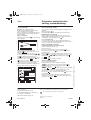
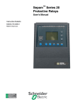
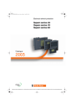
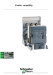
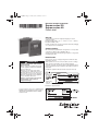
03146790FE.fm Page 1 Vendredi, 18. avril 2008 12:12 12
Electrical network protection
Sepam series 20
Sepam series 40
Quick start
03146790FE+01+NP00000000
Storage
PE50465
Sepam may be stored in its original packaging in a closed
sheltered location:
b ambient temperature: -25 °C ... +70 °C (or -13 °F ... +160 °F)
b relative humidity y 90 %.
Periodic checking of the storage environment and of the packaging
on a yearly basis is recommended.
Commissioning
Once installed, the Sepam must be energized as soon as possible,
especially in a damp location (humidity u 90 %).
Storing an unenergized and unpackaged Sepam for a long period
may damage the unit.
Identification
Each Sepam comes in a single package that contains the base
unit and its connector.
DANGER
Other optional accessories such as modules, current or voltage
input connectors and cables come in separate packages.
To identify a Sepam, check the 2 labels on the right side panel of
the base unit that describe the firmware and hardware features of
the product:
b hardware equipment label (for instance Sepam series 20)
DE80191
HAZARD OF ELECTRIC SHOCK, BURN
OR EXPLOSION
b turn off all power supplying the Sepam
and the equipment in which it is installed
before working on it.
b always use a proprely rated voltage
sensing device to confim that power is off.
b replace all devices, doors, and covers
before turning on power to this equipment.
b before energizing the power equipment,
replace all barriers and covers.
59607
Series 20/advanced UMI/24-250V
Séries 20/IHM avancée/24-250V
S10UD
Failure to observe this instruction will
result in death, serious injury or
equipment damage.
Final testing:
date and
operator code
For more informations, please refer to "Sepam series 20
Installation and user’s manual" PCRED301005EN or
"Sepam series 40 Installation and user’s manual"
PCRED301006EN.
DE80197
b firmware equipment label
59607
Test PASS: 12/14/2006
Operator: C99
03146790FE.fm Page 2 Vendredi, 18. avril 2008 12:12 12
Installation
Safety instructions
Important notes
Safety symbols and messages
Restricted liability
Read these instructions carefully and look at the equipment to
become familiar with the device before trying to install, operate,
service or maintain it. The following special messages may
appear throughout this bulletin or on the equipment to warn of
potential hazards or to call attention to information that clarifies or
simplifies a procedure.
Electrical equipment should be serviced and
maintained only by qualified personnel.
No responsibility is assumed by Schneider
Electric for any consequences arising out of the
use of this manual. This document is not
intended as an instruction manual for untrained
persons.
Risk of electric shock
Device operation
The user is responsible for checking that the
rated characteristics of the device are suitable for
its application. The user is responsible for
reading and following the device’s operating and
installation instructions before attempting to
commission or maintain it. Failure to follow these
instructions can affect device operation and
constitute a hazard for people and property.
ANSI symbol.
IEC symbol.
The addition of either symbol to a “Danger” or “Warning” safety
label on a device indicates that an electrical hazard exists, which
will result in death or personal injury if the instructions are not
followed.
Protective grounding
The user is responsible for compliance with all
the existing international and national electrical
codes concerning protective grounding of any
device.
Safety alert
This is the safety alert symbol. It is used to alert you to potential
personal injury hazards and prompt you to consult the manual.
Obey all safety instructions that follow this symbol in the manual
to avoid possible injury or death.
Safety messages
DANGER
DANGER indicates an imminently hazardous situation
which, if not avoided, will result in death, serious injury or
property damage.
CAUTION
CAUTION indicates a potentially hazardous situation which,
if not avoided, could result in minor or moderate injury or
property damage.
03146790FE-01 06/2008
2
03146790FE.fm Page 3 Vendredi, 18. avril 2008 12:12 12
Installation
Connection
b Base unit
v
base unit connector:
- 24-250 V DC, 110-220 V AC power supply
- output relay
- input CSH30 / CSH120 / CSH200 / ACE990.
Screw type connector (CCA620) represented, or
ring lug connector (CCA622).
v
1 A/5 A CT input current connector
(CCA630 / CCA634), or LPCT input current
connector (CCA670), or voltage input connector
(CCT640 series 20 only)
v
communication module link connection
(white)
v
remote inter-module link connection
(black)
v
input voltage connector (series 40 only):
screw-type connector (CCA626) represented or
ring lug connector (CCA627).
b
optional input/output modules
(MES114)
v
MES114 module connectors
DE80214
Sepam components
L
K
M
C
D
Connections
03146790FE-01 06/2008
CAUTION
HAZARD OF IMPROPER OPERATION
Do not use a CCA634 and residual current input I0 on
connector A (terminals 18 and 19).
Failure to follow this instruction can cause equipment
damage.
Installation of the optional MES114 module
b
set MES114E and MES114F selector switch on V DC or
V AC
b
insert the 2 pins on the MES114 module into the slots of the
base unit
b
push the module up against the unit to plug it into the
connector
b 4 tighten the mounting screw
PE80064
Base unit
The Sepam connections are made to the
removable connectors located on the rear of the
device.
All the connectors are screw-lockable.
Wiring of screw connectors:
b without fitting:
v maximum 1 wire cross-section: 0.2 ... 2.5 mm²
(AWG 24-12) or 2 wires with maximum crosssection: 0.2 ... 1 mm² (AWG 24-18)
v stripped length: 8 to 10 mm (0.31 ... 0.39 in)
b with fitting:
v wiring recommended with fitting
Telemecanique:
- DZ5-CE015D for 1 wire: 1.5 mm² (AWG 16)
- DZ5-CE025D for 1 wire: 2.5 mm² (AWG 12)
- AZ5-DE010D for 2 wires: 1 mm² (2 x AWG 18)
v tube length: 8.2 mm (0.32 in)
v stripped length: 8 mm (0.31 in).
Wiring of CCA622 and CCA627 connectors
b ring lug or spade lug 1/4" (6.35 mm)
b maximum wire cross-section: 0.2 to 2.5 mm²
( AWG 24-12)
b stripped length 6 mm (0.236 in)
b using a suitable crimping tool, crimp lugs onto
wires
b insert no more than 2 ring lugs or spade lugs
under washers
b torque 0.7 to 1 N•m (6 to 9 lb-in).
Wiring of CCA630 and CCA634 connectors
b ring lug or spade lug 0.16 in (4 mm)
b maximum wire cross-section of 1.5 to 6 mm²
(AWG 16-10)
b torque 1.2 N•m (11 lb-in).
3
03146790FE.fm Page 4 Vendredi, 18. avril 2008 12:12 12
Use
Advanced UMI
Example: measurement loop.
After a trip on fault (i.e. phase overcurrent):
b trip light is lit up
b I>51 light is lit up
b the graphic interface (optional advanced UMI)
displays :
v "Phase fault" message
v tripping current
v date and time of fault occurrence
b pressing the
key displays the 16 most
recent unacknowledged alarms
b pressing the
key clears the alarm
message
b pressing the
key resets the protection
relay.
DE80194
Operation
Access to measurements
and parameters
Protection and parameter
settings modes
There are 3 levels of use:
b operator level: used to read all the screens
and does not require any passwords
b protection setting level: requires the entry of
the first password (key
) allows protection
setting (key
)
b parameter setting level: requires the entry of
the second password (key
) allows
modification of the general settings as well (key
).
Changing the passwords requires the parameter
setting level. The passwords have 4 digits.
All the setting and operating functions are
available on the screen of a PC equipped with
the SFT2841 software tool and connected to the
PC connection port on the front panel of Sepam
(run in a Windows 2000, XP or Vista
environment).
All the data used for the same task are grouped
together in the same screen to facilitate
operation. Menus and icons are used for fast,
direct access to the required information.
03146790FE-01 06/2008
MT10966
The measurements and parameters may be
accessed using the metering, diagnosis, status,
and protection keys. They are arranged in a
series of screens as shown in the diagram on
the right:
b The data are split up by category in 4 loops,
associated with the following 4 keys:
v key
: measurements
v key
: switchgear diagnosis
and additional measurements:
v key
: general settings
v key
: protection settings.
b When the user presses a key, the system
moves on to the next screen in the loop. When a
screen includes more than 4 lines, the user
moves about in the screen via the cursor keys
( ,
).
4
03146790FE.fm Page 5 Vendredi, 18. avril 2008 12:12 12
Use
Parameter and protection
setting, commissioning
Use of passwords
End of passwords validity
Sepam has two 4-digit passwords:
b the first password, symbolized by a key, is
used to modify protection settings
b the second password, symbolized by 2 keys, is
used to modify protection settings and all the
general settings.
Entry of passwords
When the user presses the
key, the following
screen appears:
Access to the protection setting and parameter setting modes is
disabled:
b by pressing the
key
b automatically if no keys are activated for more than 5 mn.
Modification of passwords
Only the parameter setting qualification level (2 keys) or the
SFT 2841 allows modification of the passwords. Passwords are
modified in the general settings screen
key.
Loss of passwords
MT10958
If the factory passwords have been modified and the latest
passwords entered have been irretrievably lost by the user, please
contact your local after sales department.
Entry of parameter or setting
Schneider Electric Industries SAS
Adresse postale :
89, boulevard Franklin Roosevelt
F - 92505 Rueil-Malmaison Cedex (France)
Tel: + 33 (0) 1 41 29 85 00
http://www.schneider-electric.com
03146790FE-01
Entry of numerical values
(e.g. current threshold value).
b position the cursor on the required box using the
keys and confirm the choice by pressing the
key
b the first digit to be set is selected; set the value using the
keys (choice
0……9).
Press the
key to confirm the choice and go on to the next digit.
The values are entered with 3 significant digits and a point.
The unit (e.g. A or kA) is chosen using the last digit.
b press the
key to confirm the entry and the
key to access
the next field
b all of the values entered will only be effective after the user
confirms by selecting the apply box at the bottom of the screen
and presses the
key.
As standards, specifications, designs and dimensions develop from time to time,
always ask for confirmation of the information given in this publication.
This document has been printed on ecological paper.
Publication : Schneider Electric
Impression :
06/2008
© 2008 Schneider Electric - All rights reserved
MT10967
The 2 factory passwords are: 0000.
Press the
key to position the cursor on the
first digit 0 X X X
Scroll the digits using the cursor keys ( ,
)
then confirm to go on to the next digit by pressing
the
key. When the password for your
qualification level is entered, press the
key to
position the cursor on the apply box. Press the
key again to confirm.
When the Sepam is in protection setting mode,
one key appears at the top of the display.
When the Sepam is in parameter setting mode,
two keys appear at the top of the display.
Principle applicable to any screen of Sepam
(phase overcurrent protection eg)
b enter password
b access to corresponding screen by pressing
key
b move cursor by pressing
key to reach the desired box
(example: curve)
b press
key to confirm the selection, then select the type of
curve by pressing
or
key and confirm by pressing
key
b then press
key to reach the followings boxes, up to the
box apply
b press the
key to apply the settings.