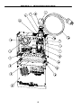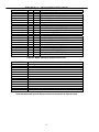
1
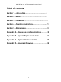
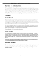
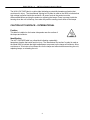
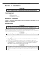
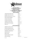
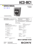
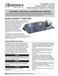
Model 6030 User’s Manual
Dry-IR
Infrared Dryers
Publication #: 107103-001 Rev. 1
March, 2004
Another quality product from:
7128 Shady Oak Road, Eden Prairie, MN 55344
Phone: (952)949-9009 Fax: (952)949-9559
E-mail: [email protected]
www.researchinc.com
Dry-IR
MODEL 6030-10
USER’S MANUAL
107103-001 REV. 1
REVISION HISTORY
REV
1
ECN NO
xxxxx
DESCRIPTION
Initial Release
DRAFT CHKR ENG.
JAR
JAR
JAR
Copyright © 2003 by Research, Inc. All rights reserved. Under copyright laws, neither the
documentation nor the software may be copied, photocopied, reproduced, translated, or reduced
to any electronic medium or machine-readable form, in whole or in part, without the prior written
consent of Research, Inc., except in the manner described in the documentation.
Research, Inc. reserves the right, without notice, to alter or improve the designs or specifications
of the products described herein. No warranty or guarantee of any kind is expressed or implied by
information contained herein.
Printed in the U.S.A.
DATE
3/15/04
Dear Valued Customer:
Thank you for purchasing a Model 6030 Dry-IR infrared dryer. We believe it is the finest
heating system of its type and are confident you will think so also.
This instruction manual has been carefully prepared to ensure you will be able to easily
install and operate the Model 6030 dryer and to fully realize all its inherent capabilities.
We invite your comments as well as any issues you may have regarding this manual or
the Model 6030.
Requirement
Appropriate Contact
Additional information regarding application
of the Model 6030 dryer or other Research Inc.
products.
Your local sales representative.
Ordering additional Research Inc. products
or Manuals.
Your local sales representative
or Research, Inc. Customer Service
(952) 949-9009
Technical assistance and training.
Research Inc. Factory Service
(952) 949-9009
Once again, let us welcome you to the growing family of Research Inc. customers. We
look forward to working with you in the future.
Sincerely,
Teery Nigon
President
Research Inc.
Model 6030 Dry IR Drying System Instruction Manual
Table of Contents
Section 1 – Introduction…………………………….…… 1
Section 2 – Safety………………………………………… 2
Section 3 – Installation……………………………………5
Section 4 – Operation Instructions……………………..11
Section 5 – Maintenance………………………………….13
Appendix A – Dimensions and Specifications………..15
Appendix B – Spare & Replacement Parts…………….17
Appendix C – Optional Tachometer Kit……………….. 20
Appendix D – Schematic Drawings……………………..24
ii
Model 6030 Dry IR Drying System Instruction Manual
Section 1 - Introduction
The Model 6030 Dry-IR Drying System is specifically designed to dry ink-jet printing. On many
types of coated stock, the water or solvent base of the ink is not easily absorbed by the material.
Instead, it remains on the surface in a liquid state and is easily smeared if touched. The Dry-IR
heater module provides the heat and air flow necessary to convert the liquid to vapor, and
quickly remove it from the surface of the paper. When used in conjunction with an ink-jet printer,
the Dry-IR Drying System can increase printing production by as much as 85 percent.
Features
Heater Module
The heater module supplied with the system features four tubular quartz lamps, an aluminum
reflector behind the lamps, side reflectors and forced air cooling. The quartz lamps have low
mass tungsten filaments allowing them to reach full operating temperature within two- to three
seconds after being turned on. The hot air comes out of the holes in the aluminum reflector and
passes between the lamps directly on to the material being dried.
The system is available with one or two heater modules which will dry ink-jet printing that is up
to 4-inches (102 mm) wide for a single unit and up to 8-inches (204mm) wide for 2 units. The
heater module is available in a 10 inch (254 mm) heated length.
Refer to Appendix A for heater module dimensions.
Power Control
The power control for the heater module is located on the top of the heater body. A process
controller controls heat output. The heat can be adjusted manually by using the buttons on the
process controller or with a closed loop circuit. The process controller will accept a 0-10 vdc, 420 ma or thermocouple input. A switch on top of the housing is provided to turn the system on
and off.
An interlock is also provided that enables the heater module to be connected to the transport.
This interlock must be satisfied for the heater module to operate.
Mounting Brackets
The optional mounting base consists of vertical and horizontal supports attached to a roll around
base, brackets for the heater module and all hardware needed for mounting. Screw holes are
located on the ends of the case for mounting to other types of supports. See Appendix A for
mounting locations.
1
Model 6030 Dry IR Drying System Instruction Manual
Section 2 – Safety
General
The Model 6030 Dry-IR Drying System is designed for safe operation. Nevertheless, installation,
maintenance and operation of the system can be dangerous for a careless operator or
maintenance person. For your safety and the safety of others, please read the instructions in
this INSTRUCTION MANUAL and follow these safety practices, which will help to prevent
accident or injury.
Infrared Radiation
CAUTION!
•
•
Continuous exposure to high intensity infrared radiation at close proximity could
be harmful to eyes or skin. Although ultra violet electromagnetic radiation is not
being emitted by infrared lamps, harmful burns could still result if an operator is
in close contact with lamps being operated at high intensity.
Because of the brilliant light emitted by infrared lamps at full intensity, it is
recommended that the eyes be shielded from the glare if observing the lamps or
radiant heat chamber for an extended period of time. Use suitable shaded lenses
or dark glasses.
Electrical Safety
There is danger of electrical shock when servicing the heater module or any item contained in
the blower housing. Even when the ON/OFF switch is in the OFF position, there is live HIGH
VOLTAGE (up to 240V) present at the power entry of the switch. The power cord is the main
disconnect for the heater.
WARNING!
•
•
•
•
•
DANGER OF ELECTRICAL SHOCK.
ALWAYS disconnect the power cord AND any optional interlock circuits before
moving, servicing, installing or replacing lamps.
NEVER operate the heater with the control box cover open or with the heater front
cover removed. This panel is designed to protect the operator from electrical
shock.
Even if the Power Switch of the control unit is in the Off position, there is live High
Voltage present at the power entry of the Power Switch, AND at the interlock
circuit when the conveyor is running.
A position sensing switch will turn the lamps OFF when the mounting arm is
raised, but HIGH VOLTAGE is still present inside the control box.
Note: All service should be performed by qualified Service
personnel.
2
Model 6030 Dry IR Drying System Instruction Manual
Fire Safety
.
CAUTION!
•
•
•
•
Jams or stoppages in the transport may cause a FIRE HAZARD.
NEVER operate the system unless an operator is present at all times.
NEVER operate the system without a FIRE EXTINGUISHER in the immediate area.
REMOVE all paper from under heater module IMMEDIATELY if the transport stops
or jams. Even though the lamps are turned off, RESIDUAL HEAT may still ignite
paper.
High Temperatures
WARNING!
•
•
•
•
Parts of the heater may exceed 500°F (260°C). Contact with the lamps, aluminum
reflectors, or metal parts near the lamps may cause severe BURNS.
NEVER place hands under the heating elements when it is operating or hot.
ALWAYS allow heating element to cool at least 15 minutes before touching the
lamps or adjacent parts.
ALWAYS wear soft, clean, oil-free flannel or plastic gloves when handling quartz
lamps.
Labels
CAUTION – INTERNATIONAL
Position
This label is installed on the front side of the housing.
Identification
The CAUTION label is a yellow label indicating a potentially hazardous situation that could
result in injury. The international “exclamation point” legend is used on the 6030 to indicate that
caution is required when operating or servicing the product due to high temperatures and high
voltage.
HIGH VOLTAGE WARNING – INTERNATIONAL
Position
This label is installed on the removable front panel of the housing.
Removing this panel allows access to the power and control
circuits within the housing.
Identification
3
Model 6030 Dry IR Drying System Instruction Manual
The HIGH VOLTAGE label is a yellow label indicating a potentially hazardous situation that
could result in injury. The international “lighting bolt” symbol is used on the 6030 to indicate that
high voltage is present inside the enclosure. All power cords to the product must be
disconnected before servicing the product or replacing the lamps. Power is present inside the
housing when the unit is tilted up, even when the position sensing circuit shuts off the lamps.
CAUTION HOT SURFACE – INTERNATIONAL
Position
This label is installed on the heater side panels near the surface of
the lamps and reflector.
Identification
The HOT SURFACE label is a yellow label indicating a potentially
hazardous situation that could result in injury. The international “hot surface” symbol is used on
the Model 6030 to indicate that high temperatures are present on the lamps and reflector. Allow
a minimum of 15 minutes of cool down time for the lamps and reflector before servicing the unit,
replacing lamps, or relocating the unit.
4
Model 6030 Dry IR Drying System Instruction Manual
Section 3 - Installation
CAUTION!
•
Please read the installation instructions carefully. It is important that the Model
6030 is installed correctly or important safety features will not be operational.
Tools Required
1. Phillips screwdriver
2. Straight blade screwdriver
Mechanical Installation
There are 4 - 5mm (10-32) mounting holes on each end of the heater for mounting the unit. See
Appendix A for dimensions.
Installing Lamps
CAUTION!
•
Wear soft, clean, oil-free flannel or plastic gloves when handling quartz lamps. If
skin oils come in contact with the quartz tube, the lamp will fail prematurely.
When installing lamps in the heater module it is important to avoid touching the quartz glass lamp tubes.
Fingerprints and dirt marks on the tube will absorb more heat and may shorten lamp life. If a lamp does get touched
or dirty, clean it with a soft tissue or cloth before using the system.
CAUTION!
•
Before installing or changing lamps, disconnect all power cords to the system.
To install or change the lamps:
1. With a Phillips screwdriver, remove the screws that fasten the front cover of the heater
module. Remove cover.
2. Loosen the 4 screws that hold the reflector in place and slide the air deflectors off.
3. Insert the lamp lead wires through the reflector and snap the lamp into the spring clips
provided (Figure 3-1). If the lamp clips are excessively tight, gently spread the clip
wider. Make sure that the lamp is held securely in the clip.
CAUTION!
•
It is important that the lead between the lamp and barrier strip not be pulled tight
when the lamp is installed. As the heater module and lamps heat and cool, they
are also expanding and contracting which may damage the lamp if the lead is too
tight.
5
Model 6030 Dry IR Drying System Instruction Manual
4. Insert the lamp lead wire into terminal blocks 1TB1-4 and 2TB1-4 and tighten the screw
terminal. Make sure that the terminal block is not tightened on the insulation of the wire.
5. When all of the lamps have been installed, check for electrical shorts to the heater’s
metal chassis and then replace the air deflectors and front cover.
Figure 3-1. Model 6030 Spring Clip and Terminal Block locations.
Electrical Installation
Connecting the Power Source
The Dry-IR Drying System must be connected to a dedicated 240V, 30-amp electrical circuit.
Secure the power cord and interlock circuit cable to the mounting arm with the supplied nylon
cable tie to keep it from being positioned under the heater module.
CAUTION!
•
The heater module requires a dedicated power circuit.
Making the Interlock Connections
The purpose of the interlock line is to prevent the heater module from operating if the transport
is not running. This helps minimize the risk of fires if paper is under the heater module when the
transport comes to a halt. The Model 6030 may be ordered with a 24VAC relay, a 24VDC relay,
or a 120VAC relay installed.
6
Model 6030 Dry IR Drying System Instruction Manual
Note: The Model 6030 will not operate unless a transport signal is supplied to the interlock
circuit.
Typically, an interlock cable is supplied from the transport and is connected on top of the blower
housing, near the ON/OFF switch.
WARNING!
•
Disconnect the power to the heater module before proceeding.
To connect the interlock to the transport:
1. Remove the gray connector from the top of the unit.
2. The white insert can be removed from the housing by loosening the 4 screws that
secure it into the housing.
3. Route the wiring through the wiring gland in the housing.
4. The interlock wiring is connected to pins 1 and 4. To prevent the heater module
from running when the transport is stopped, the transport interlock power source
needs to be off when the transport is stopped.
5. Reassemble the connector and tighten the wiring gland.
Note: After completely installing the Model 6030, please ensure the stability of
the overall assembly.
Figure 3-2
7
Model 6030 Dry IR Drying System Instruction Manual
Section 4 - Operation Instructions
Note: The lamps in the heater module will respond very quickly when turned on, but the most
effective drying results will occur after the heater module has been on for about 45 to 60
seconds. This allows the heater module enough time to start producing hot air.
Once the Dry-IR Drying System has been properly installed, it is very easy to operate. When
used with an interlock to the transport, it will operate only when the transport is running.
ON/OFF Switch
Turning the ON/OFF switch to ON will apply power to the heater module and blower.
Note: The heater module must be in the drying position, the interlock circuit must be
energized to allow the on/off switch to apply power to heater module.
Process Controller
The keys on the face of the unit operate the process controller. Additional information on
operating the controller can be found in the Watlow users Manual.
Manual Mode (Open Loop Control)
Manual mode on the process controller is indicated by the % indicator being lit. The
Auto/Manual mode can be toggled by pressing the advance key until A-M appears in the right
(green) window and pressing the up/down keys to toggle control.
8
Model 6030 Dry IR Drying System Instruction Manual
Auto Mode (Closed Loop Control)
The process controller comes with default settings for 0-10 vdc (user set 1) and a type K
thermocouple (user set 2). The controller allows a large variety of inputs that can be used to
control the process. If you are using something other than a 0-10 vdc or type K thermocouple
input as the process control, see the Watlow users manual for details on how to set up the
controller for different types of input. Use the following procedure to configure the controller for
the default settings:
1.
Press and hold the Up/down keys for 6 secs until FACt PAgE appears on the
display.
2. Use the Advance key to scroll through the displays until USrr appears in the right
(green) display.
3. Use the up/down keys to change the user default set. Set 1 is for 0-10 vdc and
Set 2 is for type K thermocouple. Allow the left display (red) to automatically
change from the chosen set to no. This will take about 10 secs.
4. Use the infinity key to return to the home page.
User Set 1 (0-10 vdc) Displays and Settings
The infinity key can be used at any time to return to the home page. The home page in this
mode will display the actual input signal in volts in the left (red) display, and the output in
percent in the left (green) display. Use the Advance button to change the display. Pressing the
advance key once will change the display to a screen to change the auto/manual mode. The
up/down keys can be used to toggle the auto/manual mode. Pressing the advance key again
will allow the user to change the voltage at which full output is achieved. If the process signal is
a 0-5 vdc signal, change this value to 5.
User Set 2 (Type K Thermocouple) Displays and Settings
The home screen with this user set will show the process variable in the left (red) screen and
the set point in the right (green) screen. Use the up/down keys to change the set point. Use the
advance key to scroll through the following screens:
Left (Red) Display
Right (Green) Display
0.0
Auto
Off
0
PID
25.00
0.0
0.0
F
PoHt
A-M
Aut
Cal
hEM
Pbht
rEht
rAht
F-C
Description
Output %
Auto/Manual mode
Auto tune feature (see Watlow manual)
Offset value for set point
Control method
Heat Gain (proportional)
Heat Reset (integral)
Heat Rate (dirivative)
Scale
9
Model 6030 Dry IR Drying System Instruction Manual
Section 5 – Maintenance
In dusty environments the lamps and impeller blades should be inspected occasionally for a
cloudy buildup. When this occurs it is recommended that they be cleaned. Doing so will extend
the life of the lamp and improve the system’s overall performance. Use the following procedure:
WARNING!
•
Disconnect all power cords from the power sources and allow the heater to cool at
least 15 minutes before continuing.
CAUTION!
•
Wear soft, clean, oil-free flannel or plastic gloves when handling quartz lamps. If
skin oils come in contact with the quartz tube, the lamp will fail prematurely
1. With a soft, dry cloth or tissue, wipe the residue from the lamps.
If a lamp burns out or breaks, refer to Appendix B, Replacement Parts, for ordering
information and to Section 3, Installing Lamps, for lamp replacement instructions.
2. Remove dust build-up on the impeller blades using compressed air.
Note: All service should be performed by qualified Service
personnel.
10
Model 6030 Dry IR Drying System Instruction Manual
Troubleshooting
PROBLEM
Lamps do not come on
SOLUTION
Make sure the fan is spinning. Check that the supply voltage is 240
VAC.
Check the Interlock connection. Power must be applied to the interlock
before the lamps will turn on. Make sure that the proper relay is
installed.
Make sure that the heater is in the heating position.
Check the tach signal. The tach signal should be 0-10 VDC, 0 is lamps
off 10 V is maximum power. Set the heater to manual mode. If the
lamps come on, check the signal from the tachometer. Try switching
the wires on the tach.
If the unit is controlled by a thermocouple, disconnect the
thermocouple. This will switch the controller to manual mode. Increase
the manual output and see if the lamps come on.
Check that CR1 has power and is energized. Check that the correct
relay has been installed.
Circuit breaker does not The undervoltage trip is not getting power. Check that the undervoltage
stay on.
trip has 24 Vdc. Verify that the power supply is producing 24vdc.
Check for short circuits to ground.
Check the supply voltage is 240 VAC.
Check the thermostat to see if it is working properly and that the unit in
not overheating.
Only some of the lamps Check for burned out lamps.
come on.
Make sure that the lamp leads have a good connection to the terminal
blocks. Make sure that the terminal blocks are not clamped on the lead
wire insulation.
Fan does not rotate.
The fan should come on as soon as the breaker is turned on. If the
breaker does not trip out, power is being applied to the system. Check
the fan wiring and connector and check the incoming power.. Replace
fan if required.
Lamps do not turn off.
The lamp control relay is getting a faulty signal. Check the wiring
connections to the control module. Replace the module if necessary.
The solid-state relay has failed. Replace the control module.
11
Model 6030 Dry IR Drying System Instruction Manual
Appendix A
Dimensions and Specifications
12
Model 6030 Dry IR Drying System Instruction Manual
Figure A-1. Model 6030 Dimensions.
Maximum Drying Width
Overall Length
Heated Length
Lamps (4 Total)
Lamp Rated Voltage
Applied Lamp Voltage
Amps at Applied Voltage
KW at Applied Voltage
Blower Air Volume
Interlock Relays
Mounting Hardware
Operator Controls
Operation Interrupts
Site Requirements
4 inches (102 mm)
15 inches (381 mm)
10 inches (254mm)
1000W-Rapido-COLL-14OAL
240 volts
240 volts
18.0 amps
4.0 KW
75 CFM (2.1m³/min)
120 VAC, 24 VAC, 24VDC
Extruded Aluminum
On/Off switch
Heat Adjustment
Automatic Heat Adjustment via Tachometer Input
Circuitry and External Tachometer Kit
(Tachometer Kit Option – ordered separately from
Drying System)
When the interlock connections are made, the heater
module will not function unless the transport is
running
240VAC/30 amp 1φ service dedicated circuit.
Personnel to position the system in place
An electrician to install a 240VAC/30 amp IEC power
cord, and connect the wiring between the power
control and the transport.
Table A-1. Model 6030 Dry-IR Specifications.
13
Model 6030 Dry IR Drying System Instruction Manual
Appendix B
Spare & Replacement Parts
14
Model 6030 Dry IR Drying System Instruction Manual
15
Model 6030 Dry IR Drying System Instruction Manual
Figure B-1. Model 6030 Spare & Replacement Parts.
16
Model 6030 Dry IR Drying System Instruction Manual
COMPONENT NO.
055899-007
070025-017
073816-001
080821-001
085143-002
085143-001
095807-003
096570-002
098212-024
098212-025
098212-026
098212-027
098215-001
099407-001
105776-002
106630-001
106656-001
106754-001
106806-001
106654-001
107131-001
QTY
1
1
1
1
1
1
1
1
1
1
1
1
1
1
1
1
1
4
1
1
1
1
ITEM
1
2
3
4A
4B
4C
5
6
7
8
9
10
11
12
13
14
15
16
17
18
19
20
DESCRIPTION
RELAY-SOLID STATE
THERMOSTAT- SURF NC 140F
CONN-T/C TYPE K YEL RND PNL
RELAY-DPDT,10A, 24VDC, 650 OHM
RELAY-DPDT,10A, 24VAC, 160 OHM
RELAY-DPDT,10A, 120VAC, 3900 OHM
FUSE 630 Ma 5mm x 20 mm
IMPELLER-5.25",170CFM 0",240V
SOCKET-DPDT; 10A; FINGERSAFE
CONN HOOD 1 LVR .75 TOP ENTRY
CONN PLG INSRT 6POS 16A 600V
CONN SCK INSRT 6POS 16A 600V
CONN-BASE PNL MTG 1 LVR 4 POS
POWER SUPPLY-24VDC, 7.5W
COVER SAFETY-SOLID STATE RELAY
CIRCUIT BRKR/SWITCH-240VAC/20A, UVT
ASSY-REFECTOR, SPEED DRY 6030
LAMP-RAPIDO 1000 W, CER.END
C/A-POWER CORD 6030 UL AND CE
FAB-END, AIR DEFLECTOR, 5060
FAB-FAN GAURD, SPEED DRY 6030
CONTROLLER 1/32 DIN WATLOW
Table B-1. Model 6030 Spare & Replacement Parts.
COMPONENT NO
106764-001
DESCRIPTION
Field Replaceable Unit kit (Includes 5 lamps and Reflector)
Table B-2 Model 6030 Spare & Replacement Parts Not Shown on Exploded View
17
Model 6030 Dry IR Drying System Instruction Manual
Appendix C
Installing the Optional Tachometer Kit
The dryer may be mounted on a variety of equipment configurations. If the tachometer supplied with
the Dry-IR system is used (Fig. C-1), it must be properly installed so that it will send a “speed signal”
to the control box ranging from zero volts when the conveyor is stopped to 10 volts when the
conveyor is at full speed. Doing so will enable the controller to operate properly, and provide the
widest range of heat control.
When a dual module system is ordered, the tachometer cable included has one end that connects to
the tachometer, and one connection to go into each of the drying modules.
The tachometer furnished with the Dry-IR system is a D.C. generator that creates a 5-volt output
when rotating at about 650 rpm. Getting the tachometer to rotate at 650 rpm when the conveyor is at
full speed requires that the correct size shaft or roller drive the O-Ring drive belt. The following two
sections explain how to determine the correctly sized driving shaft depending on the type of
equipment on which the dryer will be mounted.
Figure C-1. Tachometer and Mounting Bracket
When the potentiometer is adjusted and used in conjunction with the tachometer kit, the
potentiometer to output relationship remains the same as when run without the tachometer - the
potentiometer trim maximum output and tachometer are directly proportional to line speed. The line
speed dictates the dryer output, and the potentiometer further limits dryer output by controlling the
voltage applied to the dryer.
18
Model 6030 Dry IR Drying System Instruction Manual
Appendix D
Schematic Drawings
19