1
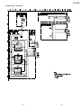
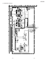
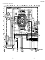
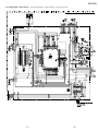
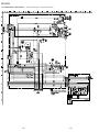
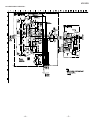
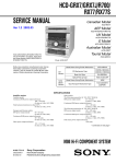
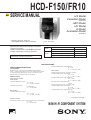
HCD-F150/FR10
SERVICE MANUAL
US Model
Canadian Model
HCD-F150
AEP Model
UK Model
E Model
Australian Model
HCD-FR10
• This set is the tuner, deck, CD
and amplifier section in MHC-F150/FR10.
photo : HCD-F150
Manufactured under license from Dolby Laboratories
Licensing Corporation.
“DOLBY” and the double-D symbol a are trademarks
of Dolby Laboratories Licensing Corporation.
Model Name Using Similar Mechanism
CD
Section
Tape deck
Section
U.S and foreign patents licensed from Dolby
Laboratories Licensing Corporation.
HCD-F100/FR1
CD Mechanism Type
CDM-46B1
Optical Pick-up Name
KSS-213D/Q-NP
Model Name Using Similar Mechanism
HCD-GRX5/RX66
Tape Transport Mechanism Type
TCM-230AWR1
SPECIFICATIONS
AUDIO POWER SPECIFICATION:
U.S.A models:
POWER OUTPUT AND TOTAL HARMONIC DISTORTION:
with 8 Ω loads both channels driven, from 70–20,000 Hz; rates 100W
per channel minimum RMS power, with no more than 0.9% total
harmonic distortion from 250 mmW to rated output.
Amplifier section
North American models:
Front Speaker:
Continuous RMS power output
100 + 100 W
(8 Ω at 1 kHz, 10% THD)
Total harmonic distortion
less than 0.09%
(8 Ω at 1 kHz, 40W)
Rear Speaker:
Continuous RMS power output
12.5 + 12.5 W
(16 Ω at 1 kHz, 10% THD)
European models:
The follwing measured at AC 230 V, 50 Hz DIN power output (Rated)
50 + 50 W
(8 Ω at 1 kHz, DIN)
MICROFILM
Continuous RMS power output (Reference)
60 + 60 W
(8 Ω at 1 kHz, 10% THD)
Other models:
The follwing measured at AC 120/240 V, 50/60 Hz
Continuous RMS power output (Rated)
110 + 110 W
(8 Ω at 1 kHz, 1% THD)
Continuous RMS power output (Reference)
130 + 130 W
(8 Ω at 1 kHz, 10% THD)
Peak music power output (Reference)
1500 W
The follwing measured at AC 110/220 V, 60 Hz
Continuous RMS power output (Rated)
90 + 90 W
(8 Ω at 1 kHz, 1% THD)
Continuous RMS power output (Reference)
110 + 110 W
(8 Ω at 1 kHz, 10% THD)
— Continued on next page —
MINI HI-FI COMPONENT SYSTEM
SECTION 3
TEST MODE
[MC Cold Reset]
* The cold reset clears all data including preset data stored in the
RAM to initial conditions. Execute this mode when returning
the set to the customer.
Procedure:
1. Press the three buttons STOP , ENTER and FUNCTION at
the same time.
2. The fluorescent indicator tube turns off for a moment and the
RAM is reset to the initial conditions.
[MC Hot Reset]
* This mode resets the set with the preset data kept stored in the
memory. This hot reset mode is performed also when the power
cord is plugged in and out.
Procedure:
1. Press the three buttons STOP , ENTER and GROUP 1 at the
same time.
2. The fluorescent indicator tube turns off for a moment and the
RAM is reset to the initial conditions.
[CD Initial]
* The CD INITIAL clears all of the CD related data. Execute
this mode when returning the set to the customer.
Procedure:
1. Press the three buttons STOP , ENTER and GROUP 4 at the
same time.
2. The message “ALL ERASE” appears on the fluorescent
indicator tube and the CD related data is reset to the initial
conditions.
[CD Line Test]
* The CD Line test displays the rotating time required for one
rotation by rotating the disc tray.
Procedure:
1. Press the three buttons STOP , ENTER and GROUP 5 at the
same time. The CD PLAY LED and the CD PAUSE LED flash
alternately and the disc tray starts rotation.
2. The message “xx << y.y” appears on the fluorescent indicator
tube. The left numbers count up the discs starting from 1 to 51.
The left numbers “y.y” indicate the rotating time required for
one rotation by rotating the disc tray.
3. To exit the CD LINE test mode, execute the MC Hot Reset.
[CD Memo All Clear]
* The mode clears all contents of the CD disc memo. Execute
this mode when returning the set to the customer.
Procedure:
1. Press the two buttons MEMO INPUT and FLASH at the
same time.
2. The message “ALL ERASE” appears on the fluorescent
indicator tube and the CD disc memo is all cleared.
[GC Test Mode]
* This mode checks microprocessor version number, keys,
fluorescent tubes, LEDs and VACS (Variable Attenuation
Control System).
Procedure:
1. Press the three buttons STOP , ENTER and GROUP 2 at the
same time. The HCD-F250 enters the GC test mode, and all of
the fluorescent tubes and LEDs turn on.
2. From this state, any one of the three modes GROUP 1, GROUP
2 and GROUP 3 can be selected. Go to step 3 to enter the
GROUP 1 test mode. Go to step 5 to enter the GROUP 2 test
mode. Go to step 11 to enter the GROUP 3 test mode.
3. [GROUP 1 test mode ] From the state of step 2, press the
GROUP 1 button. Every pressing of the GROUP 1 button
advances the following check modes and displays in the given
order. Model name display, destination display, MC version
display, GC version display, DC version display, VC version
display and CC version display.
4. To exit the GC test mode and to return to the STANDBY mode,
press the STOP , ENTER and GROUP 2 buttons again.
5. [GROUP 2 test mode ] You can enter this mode directly from
step 2. When you performed steps 3, perform steps 4, then 1
and 2 before starting the step 5.
[GROUP 2 test mode ] From the GC test mode, press the
GROUP 2 button to enter the key check mode. The display: K
1, J 0, V 0 appears.
6. The value after K indicates the number of times that the key is
pressed. 1 is displayed because the GROUP 2 button has
already been pressed.
7. When other keys are pressed one after another, the key count
increases up to 42. The keys which have already been pressed,
are not counted.
8. The value after J indicates the number of clicks that the JOG
dial is rotated. The clockwise rotation increases the count value.
The counter-clockwise rotation decreases the count value.
9. The value after V also indicates amount of rotation of volume
control. The clockwise rotation increases the count value. The
counter-clockwise rotation decreases the count value.
10. To exit the GC test mode and to return to the STANDBY mode,
press the STOP , ENTER and GROUP 2 buttons again.
11. [GROUP 2 test mode ] You can enter this mode directly from
step 2. When you performed steps 3, perform steps 4, then 1
and 2 before starting the step 5.
[GROUP 3 test mode ] From the GC test mode, press the
GROUP 3 button to enter the VACS attenuation check mode.
The display: VOL NORMAL appears.
12. To exit the GC test mode and to return to the STANDBY mode,
press the STOP , ENTER and GROUP 2 buttons again.
[MC Test Mode]
* This mode checks operation of amplifier and cassette deck.
How to enter the MC test mode:
Press the three buttons of STOP , ENTER and GROUP 3 . “EQ
CHECK” display on the FL tube and the VOLUME display flash.
In addition the LEDs of the JOG dial, FF and REW flash indicating
the MC test mode.
Check procedure:
You can perform any of the following five steps. However, it is
recommended to perform them in the following order because the
skipped cannot be performed if the checks are not performed in the
given order.
1. EQ Check Mode
The GEQ becomes maximum when the JOG dial is turned
clockwise.
The GEQ becomes minimum when the JOG dial is turned
counter-clockwise.
The GEQ comes to center when the FILE SELECT button is
pressed.
— 16 —
2. VOLUME Check Mode
The maximum volume is set, and the VOLUME MAX display
and the GEQ display are displayed for a moment regardless of
the amount of volume rotation.
The minimum volume is set, and the VOLUME MIN display
and the GEQ display are displayed for a moment regardless of
the amount of volume rotation.
3. Deck Check Mode
Install a tape to the deck B. Select TAPE B with the FUNCTION
button.
Recording starts and PAUSE is released when the REC button
is pressed.
VIDEO is selected by the input FUNCTION.
Press the STOP button to stop recording and select TAPE B
with the FUNCTION button.
Rewind the tape by pressing the REW button and stop at the
recording start point. Start playback from the recording start
point.
4. High Speed Check Mode-1
Install a tape to the deck A. Select TAPE A with the FUNCTION
button.
Press the PLAY button then press the HI-SPEED DUBBING
button during playback.
The normal playback is obtained during normal speed playback
and the double speed playback is obtained during the double
speed playback.
5. High Speed Check Mode-2
Install a tape to the deck B. Select TAPE B with the FUNCTION
button.
Press the REC button. When the PAUSE is released , recording
is started.
When the HI-SPEED DUBBING button is pressed during
recording, the double speed recording is established only when
the button is pressed.
[Aging Mode]
The decks A and B are operated automatically for aging purpose.
When errors occur during aging, causes of errors are displayed and
the aging mode is stopped.
5. The tape A is rewound and stops at the shut-off. The aging
mode advances to the next step.
The message: TAPE A AG-5 appears.
6. The tape B is played back in the FWD mode. After two minutes
of the FWD playback, the aging mode advances to the next
step.
The message: TAPE B AG-2 appears.
7. The tape B runs in fast forward. After two minutes of fast
forward, or at the shut-off point, the tape is stopped and the
aging mode advances to the next step.
The message: TAPE B AG-3 appears.
8. The tape B is played back in the RVS mode. After two minutes
of the RVS playback, the aging mode advances to the next step.
The message: TAPE B AG-4 appears.
9. The tape B is rewound and stops at the shut-off. The aging
mode advances to the next step.
The message: TAPE B AG-5 appears.
[Function Change Mode]
* Select either VIDEO or MD of the external FUNCTION input.
Procedure:
1. Turn off the power.
2. Press the two buttons ENTER and POWER at the same time.
The main power is turned on and the other function of the
previous function is selected and displayed. “MD” or “VIDEO”
[AM TUNER STEP 9 kHz/10 kHz Selection Mode]
* Either the 9 kHz step or 10 kHz step can be selected for the AM
channel step.
Procedure:
1. Turn on the power and select TUNER using the FUNCTION
button.
2. Select AM with the TUNER/BAND button and turn off the
power.
3. Press the two buttons ENTER and POWER at the same time.
The main power is turned on and the other frequency step of
the previous mode is selected and displayed. “AM 9k STEP”
or “AM 10k STEP”
How to enter the aging mode
1. Turn on the main power. Install a playback tape to deck A and
install a blank tape to deck B.
2. Select TAPE A with the FUNCTION button.
3. Press the three buttons of STOP , ENTER and GROUP
ENTRY at the same time to enter the aging mode.
How to exit the aging mode.
Turn off the main power.
1. Rewind the tapes A and B. Tapes stop at the shut-off of tape A
and the aging mode advances to the next step.
The message: TAPE A AG-1 appears.
2. The tape A is played back in the FWD mode. After two minutes
of the FWD playback, the aging mode advances to the next
step.
The message: TAPE A AG-2 appears.
3. The tape A runs in fast forward. After two minutes of fast
forward, or at the shut-off point, the tape is stopped and the
aging mode advances to the next step.
The message: TAPE A AG-3 appears.
4. The tape A is played back in the RVS mode. After two minutes
of the RVS playback, the aging mode advances to the next step.
The message: TAPE A AG-4 appears.
— 17 —
HCD-F150/FR10
6-6. SCHEMATIC DIAGRAM — BD SECTION —
• See page 71 for Waveforms. • See page 72 for IC Pin Functions.
— 37 —
— 38 —
HCD-F150/FR10
6-8. SCHEMATIC DIAGRAM — CD MOTOR SECTION —
— 41 —
— 42 —
HCD-F150/FR10
6-10. SCHEMATIC DIAGRAM — AUDIO SECTION —
BOARD
P MAIN
CN106
(Page 55)
16
— 45 —
— 46 —
HCD-F150/FR10
6-12. SCHEMATIC DIAGRAM — LEAF SW SECTION —
Q
MAIN BOARD
CN107
(Page 55)
16
— 49 —
— 50 —
HCD-F150/FR10
6-14. SCHEMATIC DIARGAM — MAIN (1/5) SECTION —
69
— 53 —
— 54 —
HCD-F150/FR10
6-15. SCHEMATIC DIARGAM — MAIN (2/5) SECTION —
— 55 —
• See page 51 for Printed Wiring Board. • See page 71 for Waveforms. • See page 77 for IC Pin Functions.
— 56 —
HCD-F150/FR10
6-16. SCHEMATIC DIARGAM — MAIN (3/5) SECTION — • See page 51 for Printed Wiring Board. • See page 71 for Waveforms. • See page 76 for IC Pin Functions.
— 57 —
— 58 —
HCD-F150/FR10
6-17. SCHEMATIC DIARGAM — MAIN (4/5) SECTION — • See page 51 for Printed Wiring Board. • See page 80 for IC Black Diagrams.
70
— 59 —
— 60 —
HCD-F150/FR10
6-18. SCHEMATIC DIARGAM — MAIN (5/5) SECTION — • See page 51 for Printed Wiring Board.
70
— 61 —
— 62 —
HCD-F150/FR10
6-20. SCHEMATIC DIAGRAM — PANEL SECTION —
• See page 80 for IC Black Diagrams.
— 65 —
— 66 —
HCD-F150/FR10
6-22. SCHEMATIC DIAGRAM — POWER SECTION —
— 69 —
— 70 —