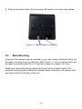
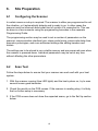
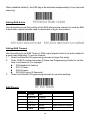
1
Revision History Changes to the original manual are listed below: Version Date Description of Version 1.0 Apr. 30, 2010 Initial release 1.1 Dec.27,2010 Changed procedures in host connection and mounting plate installation. 1.2 Mar.14, 2011 Updated AUX and EAS instructions. Important Notice No warranty of any kind is made in regard to this material, including, but not limited to, implied warranties of merchantability or fitness for a particular purpose. We are not liable for any errors contained herein or incidental or consequential damages in connection with furnishing, performance or use of this material. No part of this document may be reproduced, transmitted, stored in a retrieval system, transcribed, or translated into any language or computer language in any form or by any means electronic, mechanical, magnetic, optical, chemical, manual or otherwise, without express written consent and authorization. We reserve the right to make changes in product design without reservation and without notification. The material in this guide is for information only and is subject to change without notice. For the latest revision please contact your distributor. All trademarks mentioned herein, registered or otherwise, are the properties of their various respective owners. Copyright © 2011. All rights reserved. This manual is in A5 format. Please check your printer setting before printing it out. Laser Safety The Advanced Compact Dual-Laser Omnidirectional Vertical Scanner complies with safety standard IEC 60825 for a Class I laser product. It also complies with CDRH as applicable to a Class IIa laser product. Avoid long term staring into direct laser light. Radiant Energy: The Dual-Laser Omnidirectional Vertical Scanner uses two low-power visible laser diodes operating at 650nm in an opto-mechanical scanner resulting in less than 3.9µW radiated power as observed through a 7mm aperture and averaged over 10 seconds. Do not attempt to remove the protective housing of the scanner, as unscanned laser light with a peak output up to 0.8mW would be accessible inside. Laser Light Viewing: The scan window is the only aperture through which laser light may be observed from this product. A failure of the scanner motor, while the laser diode continues to emit a laser beam, may cause emission levels to exceed those for safe operation. The scanner has safeguards to prevent this occurrence. If, however, a stationary laser beam is emitted, the failing scanner should be disconnected from its power source immediately. Adjustments: Do not attempt any adjustments or alteration of this product. Do not remove the protective housing of the scanner. There are no user-serviceable parts inside. Caution: Use of controls or adjustments or performance of procedures other than those specified herein may result in hazardous laser light exposure. Optical: The use of optical instruments with this product will increase the eye hazard. Optical instruments include binoculars, magnifying glasses, and microscopes but do not include normal eye glasses worn by the user. For CE-Countries This scanner is in conformity with CE standards. Please note that an approved, CE-marked power supply unit should be used in order to maintain CE conformance. Table of Contents Introduction.................................................................................................................. 1 Unpacking ................................................................................................................... 2 Finding Your Way Around Outline ............................................................................................................... 3 Caution Label..................................................................................................... 5 Cable Installation ............................................................................................... 5 Connection Power................................................................................................................. 6 Connecting to the Host ...................................................................................... 6 Connecting Auxiliary Scanner ............................................................................ 7 Connect EAS ..................................................................................................... 7 Verifying Scanner Operation .............................................................................. 7 Interface Cable Replacement ............................................................................ 9 Mounting Diagrams for Mounting....................................................................................... 11 Mounting Plate Installation ................................................................................. 12 Auxiliary Handheld Scanner Connection (Optional) ........................................... 14 Back Mounting ................................................................................................... 15 Site Preparation Configuring the Scanner .................................................................................... 16 Scan Test ........................................................................................................... 16 Set Up................................................................................................................ 17 Controlling the Scanner from POS System........................................................ 18 Setting EAS System........................................................................................... 18 Operation LED Indications.................................................................................................. 20 Sound Indications .............................................................................................. 20 Tone and Volume Adjustment ............................................................................ 21 Sleep Mode........................................................................................................ 22 How to Scan Scan Volume...................................................................................................... 23 Scanning Mode .................................................................................................. 24 Maintaining the Scanner.............................................................................................. 25 Trouble Shooting ......................................................................................................... 36 Specification ................................................................................................................ 37 Dimension ................................................................................................................... 38 Decode Zone............................................................................................................... 39 Pin Assignment Device................................................................................................................ 30 Interface Cable................................................................................................... 31 1. Introduction The Advanced Compact Dual-Laser Omnidirectional Vertical Scanner is a vertical scanner empowered with dual-laser technology, enabling 40 scan lines at a rate of 3600 scans per second. Along with the proprietary hardware decoding technology, the scanner guarantees unbeatable decoding speed and accuracy, the best choice for high-traffic applications, including hypermarket, healthcare, warehouse management and manufacturing process control. When working in field, the scanner has a two-color LED to provide immediate visual feedback. It also has two advanced touch control sensors in the front, allowing beeping tone and volume adjustment. With a built-in EAS antenna, field-replaceable interface cable and an additional handheld scanner port, the Advanced Compact Dual-Laser Omnidirectional Vertical Scanner is the ultimate device for users demanding functionality and quality. Key Features: Unique dual-laser technology Proprietary hardware decoding technology Large scan field Barcode stitching capable Instant “object-fly-by” automatic wake-up Easy on-site configuration Touch control sensors for sound indication adjustment 1 2. Unpacking The omnidirectional scanner package contains: 1 ea. Advanced compact dual-laser omnidirectional vertical scanner 1 ea. Interface cable (This cable is usually, but not always, supplied. Model depends on customer needs.) 1 ea. 9V power adapter (Model depends on electrical requirements of your geographic location) 1 ea. User’s manual & programming guide in CD-ROM a. Please leave this user’s manual within easy access for persons using the scanner. b. If any contents are damaged or missing, please contact your dealer immediately. 2 3. Finding Your Way Around 3.1 Outline Figure 1: Outline 3 Figure 2: Connector Panel Description Function Scan Window Read barcodes Speaker Exit For beep tone indication LED Indicator Reading status indication Tone Adjustment Adjusting sound indication tone Volume Adjustment Adjusting sound indication volume Back Mounting Holes For permanent fixture (optional) Cable Release Hole Connecting interface cable Interface Cable Connection For interface communication connection to the host AUX Connection Connecting an auxiliary scanner (optional) EAS Connection Electronic Article Surveillance connection (optional) 4 3.2 Caution Label Figure 3: Label 3.3 Cable Installation The scanner is to be connected to a host (e.g. POS). The use of external power is determined by your host but it is usually recommended. The scanner also supports an auxiliary scanner and EAS application. The figure below gives you an overview of the cable installation. Figure4: Cable Installation 5 4. Connection 4.1 Power The scanner requires a minimum of 450mA at 9 V DC power. The interface cable that comes with the scanner supports both direct power (where the scanner takes power from the host machine) and external power (that's what the supplied power adapter is for). A sufficiently robust POS system can support a scanner successfully without external power; a POS system with a barely adequate power supply may produce erratic performance (either of the POS system itself, or of the scanner, or both) when a scanner is attached. Unless you are sure your POS system can handle the load, it is recommended that you use the supplied power adapter. When an external adapter is connected, the scanner does not take power from the host. The scanner turns on when power is supplied, and turns off when power is removed. There is no on/off switch on the scanner itself. Use only an AC/DC power adapter approved for the scanner. Use of other power supplies may cause damage to the product, and void the factory warranty. Follow the steps below when you need an external power connection to the scanner (Refer to Figure 4): 1. Connect the interface cable to the bottom of the scanner. 2. Connect the other end of the interface cable to the host (refer to your host manual to locate the correct port). 3. Plug the power supply into the power jack on the interface cable. 4. Plug the other end of the power supply into an AC outlet. 4.2 Connecting to the Host The interface cable comes with different host-end connectors, depending on the host. Follow the steps below to connect the interface cable to the host. 1. Make sure that the power of the host system is off. 2. Plug the host end of the interface cable to the appropriate connector on the host system. 3. For those cases where external power is used, plug the external AC power adapter into the jack on the interface cable. 4. Turn on the host system. 6 4.3 Connecting Auxiliary Scanner To connect an auxiliary scanner to the AUX port: 1. 2. 3. 4. 4.4 Connect the auxiliary interface cable to the auxiliary port of the scanner. Connect the other end of the cable to the auxiliary scanner. Connect the power supply if necessary. Use the programming barcodes to activate the auxiliary port of the vertical scanner and set up its data transmission mode. (Refer to its separate Programming Guide.) Connecting EAS The scanner’s integrated EAS deactivation antenna requires an EAS host cable. 1. Make sure that the power of the EAS system is off. 2. Plug the cable to the appropriate connectors on the scanner and the EAS system as illustrated in Figure 4. 3. Turn on the EAS system. 4.5 Verifying Scanner Operation Before mounting your scanner, please follow the procedure below to verify scanning operation. 1. Take a stick to poke in the hole at the back of the scanner to remove the mounting plate. Figure 5: Mounting Plate Removal 2. Insert the 10-pin modular plug of the interface cable into the “Host” connector 7 Figure 6: Host Cable Connection 3. Insert the bracket on interface cable to the cable release hole of the mounting plate as shown. Make sure the flat side of the bracket goes in first Figure 7: Cable Holder 4. Insert the latches of the mounting plate into the latch holes of the scanner. Figure 8: Latches 5. Close the mounting plate as shown in the figure. 8 Figure 9: Put the mounting plate back 6. Plug the other end of the cable to the host. 7. Plug the power adapter into the jack on the interface cable. 8. Plug the AC end of the power adapter into an AC outlet. The scanner powers up, the speaker sounds four beeps and the LED indicator glows blue. 9. Present a known-good test barcode to the scanner. The scanner should issue a short beep and the LED should flash red momentarily. If the scanner is connected to a keyboard wedge for this test, it should read one barcode, beep, and the LED remain red. This is normal when the keyboard wedge is not connected to a live host terminal. The LED would flash red and read no barcode if the scanner is programmed in USB interface but not connected to a host device. If the scanner does not produce any beeps, or produces the wrong beeps, or the LED is not lit up, remove the power connection and refer to the section of Troubleshooting. 4.6 Interface Cable Replacement The interface cable comes with different host-end connectors, and there are 5 standard types of interface connection that this device supports: (a) Keyboard wedge (b) RS-232 interface (c) USB interface (supporting HID USB, virtual COM, OPOS USB) The standard interface cable is attached to the scanner with a 10-pin modular 9 connector. When properly seated, the connector is secured in the scanner bottom by a flexible retention tab. The cable is designed to be field replaceable. Replacement cables can be obtained from your authorized distributor. To replace the cable, follow these steps. 1. Make sure that the power of your computer system is switched off. If a power adapter is used, disconnect it from the scanner cable. 2. Disconnect the old scanner cable from the computer system. 3. Use a stick to remove the mounting plate from the scanner. (See 4.3). 4. Press down the small tab on the connector where the old cable is attached to the scanner and pull out the connector. 5. Insert the 10-pin modular plug of a new interface cable into the “Host” connector at the back of the scanner until it clicks. 6. Insert the connecting cable in the slot of the mounting plate. 7. Mate the scanner and the mounting plate, engaging the tab on the underside. Be careful not to pinch the cable. 8. Plug the new cable into the host. 9. If a power adapter is used, plug the power adapter into the jack on the interface cable. 10.Re-program the scanner interface setting with barcodes in the Programming Guide. 5. Mounting After the scanner passes its verification test, you may proceed with mounting for permanent fixture. The scanner should be installed in a location away from direct sunlight; high levels of ambient light reduce scanner effectiveness. The two basic styles of mounting are a) with the included mounting plate, and b) with a custom bracket (not included) for back mounting. If an auxiliary handheld scanner is to be attached, it must be properly connected as part of the mounting process. 10 5.1 Diagrams for Mounting The device is reserved with 2 mounting holes at the back and 4 mounting holes at bottom. Refer to the figure below for detailed information. Back View Unit: mm (inch) Figure 10: Diagrams for Mounting (Back) Bottom View Unit: mm (inch) Figure 11: Diagrams for Mounting (Bottom) 11 5.2 Mounting Plate Installation 1. Position the mounting plate in the desired location and secure it in place. Figure 12: Mounting Hole Positions 2. Insert the interface cable in the cable release hole of the mounting plate. Figure 13: Position the interface cable 3. Insert the 10-pin modular plug of the interface cable into the “Host” connector at the back of the scanner until a firm click is heard. 12 4. Move the scanner into position on the mounting plate, engaging the tab on the underside. Be careful not to pinch the cable. Figure 14: Slide the mounting plate into scanner 13 5.3 Auxiliary Handheld Scanner Connection (Optional) The scanner supports the operation of an auxiliary handheld scanner, which may be connected via a 10-pin modular plug to the connector marked “AUX” at the back of the scanner. 1. Insert the 10-pin modular plug of scanner cable into the “Host” connector at the back of the scanner until a firm click is heard. 2. Take a knife to cut open the rectangular reserved hole. Figure 15: Routing Hole for Handheld Scanner Cable 3. Route the auxiliary cable through the rectangular hole. 4. Insert the auxiliary cable connector into the 10-pin “AUX” jack until a firm click is heard. Figure 16: Insert the scanner cable and the auxiliary Cable 14 5. Slide the mounting plate into the scanner. Be careful not to pinch any cables. Figure 17: Cable installation completed 5.4 Back Mounting If desired, the scanner may be mounted to your own custom bracket by using the threaded mounting holes at the back (See Figure 1). The mounting holes are threaded to accommodate M3 x 0.5 machine screws to a depth of 6.0 mm. Make sure your bracket design allows for the exit of the interface cable. The supplied mounting plate protects the interface cable connection, but requires that the cable exits from the back of the unit. 15 6. Site Preparation 6.1 Configuring the Scanner In certain cases no setup is required. The scanner is either pre-programmed to suit the situation, or it automatically detects and is ready to go. In other cases the scanner must be informed about what kind of system it is connected to. This can be done in a few moments using the programming barcodes in the separate Programming Guide. The programming section may be used to set a number of parameters on the scanner: communication interface type, sleep mode timing, same-code delay time, barcode symbologies, and more advanced settings like setting headers and trailers. The settings are to be stored in non-volatile memory and are preserved even when the scanner is powered down. Individual parameters may be set at any time without affecting the other parameters. 6.2 Scan Test Follow the steps below to ensure that your scanner can work well with your host system. 1. With the scanner running (blue LED lights) and the host system on, try to scan several known-good barcodes. 2. Check the results on the POS screen. If the scanner is reading okay, it is likely that no further setup is necessary. 3. If the POS screen does not show the expected scans, go to the Set Up section below. 16 6.3 Set Up 1. When the scanner is powered on (blue LED lights), find the <Enter/Exit Programming Mode> barcode in the Programming Guide and present this barcode to the scanner. When the scanner gives two beeps (one low and one high) and the LED turns red, it means the scanner is in programming mode. 2. Decide which parameters are required and find their barcodes in the Programming Guide. 3. Cover unwanted codes with your hand and present the desired codes one by one to the scanner; the scanner beeps once as it accepts each code. 4. When done, again present the <Enter/Exit Programming Mode> barcode. 5. The scanner beeps twice of the same tone, and the LED returns to blue. It means the scanner has been programmed. 6. Test again with known-good barcodes. If results are good, you are done setting up. Otherwise, return to step 1 and try again. Read Enter/Exit Programming Mode barcode to start configuration Change scanner setting by scanning the barcodes of the desired function Read Enter/Exit Programming Mode barcode to save and exit Figure 15: Programming Procedure 17 6.4 Controlling the Scanner from POS System The scanner can be controlled from the POS system via the RS-232C interface. Controlling can be accomplished by transmitting the following single byte commands to the scanner. The default settings of the commands are as follows: ASCII Code 0E Hex 0F Hex 05 Hex 12 Hex 14 Hex Function enable (resumes disable) disable power-up re-initialization sleep wake up (resumes sleep) Byte is Also Called: Shift Out or <Ctrl-N> Shift In or <Ctrl-O> ENQ or <Ctrl-E> DC2 <Ctrl-R> DC4 <Ctrl-T> When the scanner is disabled (unable to scan), the motor of the scanner will stay on until the scanner goes into sleep mode. 6.5 Setting EAS System The scanner supports the use of an EAS antenna and can work simultaneously with an EAS system using the interlock feature. When enabled, users may scan and deactivate an item at the same time. To setup the scanner: 1. Scan the Enter/Exit Programming barcode to begin the setup. 2. Scan the setting barcodes to setup the scanner. Multiple setup barcodes can be scanned at this step. Scan the Enter/Exit Programming barcode again when you are done to save 3. the settings. Setting EAS Interlock When enabled, the EAS tag is not de-activated until the associated barcode is decoded. 18 When disabled (default), the EAS tag is de-activated independently of any barcode scanning. Setting EAS Active Use this setting to set the polarity of the EAS allowing the scanner to send an EAS output after a good barcode read to deactivate a tag on the product. Setting EAS Timeout Use this setting to set EAS Timeout. EAS output signal is held in its active state for a good read indication. To set the timeout: 1. Scan the Enter/Exit Programming barcode to begin the setup. 2. Scan 3 ASCII number barcodes (Please see Programming Guide) to set the time in millisecond. For example: 000:disable the feature 001:10 msec 002:20 msec 250:2500 msec (2.5second) 3. Scan the Enter/Exit Programming barcode to save the settings. EAS Pin-out 1 2 3 4 5 6 Function Ground Antenna+ AntennaEAS In EAS Out Shield Color Red Orange Black Green White Purple 19 Note Open collecor output 7. Operation 7.1 LED Indications There are red and blue dual color LED indications on the head of the device indicating the operational status of the scanner. LED Status Indication LED off No power supplied to the scanner. Steady blue light The scanner is powered on and ready to scan. One red flash A barcode has been successfully decoded. Steady red light A barcode has been successfully decoded, but the object is not removed from the scan window. The scanner is in programming mode. Flashing blue light The scanner is in sleep mode. Steady red/blue light This indicates the scanner has a motor or laser failure. For motor failure, a periodic beep is sounded. In this case, return the unit for repair. Flashing red light The scanner is programmed in USB interface but not connected to a host device. 7.2 Sound Indications The device uses a speaker to give audio feedback on scanner operation. The following are the sound indications. Beeps Indication One beep A barcode has been successfully decoded. Two beeps: low-high The scanner has entered programming mode. Two beeps: same tone Scanner has returned from programming to normal mode. Four beeps in series This indicates the scanner passed self-test when powered on and is operating properly. Continuous tone This is a failure indication. Return the unit for repair. 20 7.3 Tone and Volume Adjustment The scanner can be programmed with the Programming Guide to change beeper tone, volume and duration; the tone and volume can also be changed by using the touch control sensors in the front. Touch Control Sensor Tone Volume There are three tones to choose from. Gently touch the note sign and the scanner would change to its next tone. Repeat touching till the desired tone is heard. On the other hand, there are three levels of volumes to choose from. To change the volume, gently touch the volume sign and the scanner would cycle to its next level. Repeat touching it till the desired level is reached. Figure 18: Tone & Volume Adjustment The volume setting is saved in volatile memory. That means the change will lost when the scanner powers down. On next power-up the scanner would reset to the configured setting. If you wish to keep the changed volume setting, use the Programming Guide to set and save the changes. 21 7.4 Sleep Mode After the scanner has been inactive for a specific length of time, the laser and the motor would automatically turn off and the scanner would enter the sleep mode. The blue LED would blink as indication. It takes 2 steps to enter the sleep mode. The first step is the laser switching off after 10 minutes; the second step is the motor switching off after 30 minutes. The time period is programmable. To wake up the scanner, simply present an object into the IR detection range in front of the scan window or touch the sound indication sensors. Figure 19: IR detection range The scanner includes a motion sensor that detects activity in front of the scan window. The detecting distance is about 10cm (3.9 inch) from the scan window while in condition with effectiveness of environment lights. The detecting distance is also programmable. 22 8. How to Scan 8.1 Scan Volume The device is an omnidirectional presentation scanner with a 10-direction scan field with a 40-line scan pattern. The scan volume extends approximately 20cm (8”) in front of the scan window. Barcode labels can be easily read when presented towards the scanning window. The scanner’s scan volume is illustrated as Figure 13. Figure 20: Scan Volume 23 8.2 Scanning Mode The scanner can read barcodes in either sweep or presentation mode to accommodate different requirements. Sweep Mode means moving items through the scan volume. Left to right, right to left, top to bottom, bottom to top, etc. are all okay. Sweep Mode is usually used for high throughput and reduced product handling. Figure 21: Sweep Mode Presentation Mode is used where counter top space is at a premium. The product is moved toward the scan window (“presented”) until the barcode is read, then the product is removed. Figure 22: Presentation Mode 24 9. Maintaining the Scanner The scanner is designed for long-term trouble-free operation and rarely requires any maintenance. Only an occasional cleaning of the scanner window is necessary in order to remove dirt and fingerprints. It can be cleaned while the scanner is running. When cleaning the scan window, wipe the scan window with a soft lint-free cloth and a non-abrasive cleaner to avoid scratching and damaging the scan window. Do not spray water or cleaning liquid directly into the window. If the scanner’s housing needs cleaning, use a mild cleaning agent that does not contain strong oxidizing chemicals; otherwise the exterior may be damaged. 25 10. Trouble Shooting This section contains information about how to solve problems that you may encounter when operating the scanner. However, before referring to the tips, make sure that the scanner is installed as instructed in this manual and that all cables are properly connected. If the problem remains, please contact your dealer. Problem Diagnostic Tips The scanner is on but cannot read barcodes. The LED is red. The scanner is on, but the motor is not rotating. A barcode cannot be read. The LED is intermittently flashing blue. Both the red and blue LED light up (appearing the color purple) and remain flashing. The scanner window is dirty. Clean the scanner window as described in the Maintenance section. The presented barcode type is not enabled. Select the barcode type in the Programming Guide. The host disables the scanner. The barcode type you presented to the scanner is not supported. The scanner has entered the sleep mode. Press the switch on the top of the scanner to wake up the scanner (or use the wake protocol.) The scanner does self test when powered up. The red and blue LED would both light on (appearing the color purple) when the scanner fails the self test. When it happens, disconnect the scanner from its power source immediately and contact your dealer. There is no proper handshaking with the POS system. Switch on the POS system and check the connection and communication settings. The scanner is continuously seeing a barcode. The scanner does not accept Remove all barcode labels out of the scan volume of more than two or three barcode the scanner and try again. labels. The scanner cannot send the data to the POS system. There is no proper handshaking between the scanner and the host. Make sure that all cables are connected and your POS system is ready to receive data. The interface cable is not connected to the correct port of your POS system. Refer to the manual of your POS system to locate the serial port. The communication settings of the system and A barcode is read by the scanner scanner do not match. Adjust the settings in order to but not accepted by the POS be equal for both devices. system. The interface cable does not suit your POS system. Contact your dealer for the correct interface cable. The software running on the POS system does not support the data format of the barcode label. 26 11. Specification Operational Light Source 650nm visible laser diodes (VLD) MPU 32 bit Depth of Scan Field 0 – 200 mm (UPC/EAN 100%, PCS=90%) Scan Pattern 10 directions of scan field Scan Rate 3600 scans per second (omnidirectional) Number of Scan 40 Lines Minimum Bar Width 5mil @ PCS 90% Print Contrast 30% @ UPC/EAN 100% Indicators (LED) Two-color LED (blue & red) Beeper Operation Programmable tone & volume System Interfaces Keyboard wedge, RS-232C, HID USB Height 152 mm Depth 88 mm Width 152 mm Physical Weight 685 g (without cable) Mounting Option Integral mounting plate Cable Standard 2.0M straight Input Voltage 9VDC ± 10% Power Power 4.05 watts Operating Current 450mA @ 9V (Normal) Regulatory Laser Class CDRH Class IIa; IEC 60825-1 Class 1 EMC CE EN55022 B, FCC Part 15 Class B, VCCI, BSMI Environmental Operating Temperature Storage Temperature 0°C - 40°C (32°F - 104°F) -20°C - 60°C (-4°C - 140°F) Humidity 5% ~ 90% RH (no dewing allowed) Drop Durability Designed to withstand 1.0M drops Light Levels Up to 4000 Lux (fluorescence) Compatibility EAS compatible 27 12. Dimension Unit: mm(inch) 28 13. Decode Zone 29 14. Pin Assignment 14.1 Device Host Port Pin 1 2 3 4 5 6 7 8 9 10 Host Function Keyboard RS-232C USB Wedge N.C. N.C. USB Power +9V KB_CLK DPC_CLK RTS_TTL N.C. Ground N.C. TX_TTL N.C. N.C. RX_TTL N.C. KB_DATA D+ PC_DATA CTS_TTL N.C. N.C. N.C. N.C. EAS Port Pin Function 1 GND 2 ANTENNA+ 3 ANTENNA4 EAS INPUT 5 EAS OUTPUT 6 SHIELD 30 Auxiliary Port RS-232 IN Only Pin Function 1 RX_TTL 2 N.C. 3 +5V output, 300mA max. 4 RTS_R 5 Ground 6 TX_R 7 RX_R 8 NC 9 CTS_R 10 TX_TTL 14.2 Interface Cable Keyboard Wedge Cable (for PS/2) PIN-OUT CONFIGURATION P1- MINI DIN (M) P2- MINI DIN (F) Din FUNCTION Din FUNCTION 1 PC Data 1 KB Data 2 N.C. 2 N.C. 3 GND 3 GND 4 +5V 4 +5V 5 PC Clock 5 KB Clock 6 N.C. 6 N.C. RS-232C Cable – DTE Pin Out DB-9 (F) 2 3 7 8 9 5 FUNCTION TX RX CTS RTS +5V GND DB-9 (F) 2 3 7 8 9 5 FUNCTION RX TX RTS CTS +5V GND USB TYPE A 1. 2. 3. 4. VCC DD+ GND RS-232C Cable – DCE Pin Out USB HID / Virtual COM Cable 31 FUNCTION