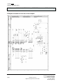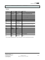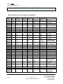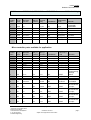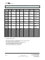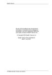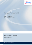
1
GAMMA instabus
OEM- Product Catalogue
Release: December 2011
KNX-Processor 78F0534/2.5, 78F0535/2.5 and 78F0537/2.5
5WG1 184-8AA_1
TECHNICAL DATA
Features
KNX Bus Processor for use on the
application PCB for high volume production.
Renesas 78K0/Kx2 microcontroller,
contains the KNX System 2.5 stack.
Processor to be connected to TPUART
PEI (Physical External Interface), 8 A//D
converter inputs, one 8-bit I/O port and two
PWMs for application available
User Flash memory
User RAM
KNX certified stack
Lead (Pb)-free device
Description
The Renesas 78K0/Kx2 microcontroller family provides state of the art flash memory technology. This
enables the application designer to utilize a modern tool chain including debug tools leading to shorter
software development times.
The application interface includes the PEI, Reset, two PWMs, 8 A/D converter ports and one 8-bit
processor port. Additional pins to connect the external programming button and LED are available.
The KNX-Processor contains the KNX certified System 2.5 stack.
Siemens AG
Infrastructure and Cities Sector,
Building Technologies
Control Products and Systems
P. O. Box 10 09 53,
D-93009 Regensburg
pages 10
© Siemens AG 2011
Subject to change without further notice.
Technical Manual
page 1
GAMMA instabus
Release: December 2011
KNX-Processor 78F0534/2.5, 78F0535/2.5 and 78F0537/2.5
5WG1 184-8AA_1
Order Numbers
Device
Order Number
User Flash
User RAM
78F0534/2.5
5WG1 184-8AA01
8 kbytes
200 bytes
78F0535/2.5
78F0537/2.5
5WG1 184-8AA11
5WG1 184-8AA21
16 kbytes
48kbytes
1.2 kbytes
5.2 kbytes
Technical data of the controller
CPU Renesas 78K0/KE2
8-Bit A/D-converter API
Two 8-Bit pulse length modulator (PLM/PWM)
Serial asynchronous communication
Serial synchronous communication in software
Input capture interrupt available
Output compare interrupt available
Application watch dog
One 8-bit timer
One 16-bit timer
Technical Manual
page 2
pages 10
© Siemens AG 2011
Subject to change without further notice.
Siemens AG
Infrastructure and Cities Sector,
Building Technologies
Control Products and Systems
P. O. Box 10 09 53,
D-93009 Regensburg
GAMMA instabus
Release: December 2011
KNX-Processor 78F0534/2.5, 78F0535/2.5 and 78F0537/2.5
5WG1 184-8AA_1
Interface block diagram
Siemens AG
Infrastructure and Cities Sector,
Building Technologies
Control Products and Systems
P. O. Box 10 09 53,
D-93009 Regensburg
pages 10
© Siemens AG 2011
Subject to change without further notice.
Technical Manual
page 3
GAMMA instabus
Release: December 2011
KNX-Processor 78F0534/2.5, 78F0535/2.5 and 78F0537/2.5
5WG1 184-8AA_1
Example schematic for the use of the chipset
Technical Manual
page 4
pages 10
© Siemens AG 2011
Subject to change without further notice.
Siemens AG
Infrastructure and Cities Sector,
Building Technologies
Control Products and Systems
P. O. Box 10 09 53,
D-93009 Regensburg
GAMMA instabus
Release: December 2011
KNX-Processor 78F0534/2.5, 78F0535/2.5 and 78F0537/2.5
5WG1 184-8AA_1
Partlist
Reference
C2
Component
Capacitor
Type/Value
6u8F
C3
C4,C10
C6,C7
C8
C1,C5
C1,C12
C9
D1
Capacitor
Capacitor
Capacitor
Capacitor
Capacitor
Capacitor
Capacitor
IC
D2
IC
470uF
47nF
12p
470nF
10nF
10nF
100n
TP-UART-IC
KNXProcessor
G1
H1
Crystal
LED
L1
R1
R2,R3
R4
R5
S1
Choke
Resistor
Resistor
Resistor
Resistor
Push Button
Supressor
Diode
Rectifier
Diode
V1
V2
9830400Hz
LST67K
B82793 /
4.7mH
2K
47K
68R
100K
KSC341J
SMAJ43CA
BYG21M
Remarks
6,3V/+-20%, Electrolytic
16V/+-20%, Electrolytic. Value
depends on desired save time
50V,/+-5%, Ceramic
Ceramic
Ceramic (see [2])
50V/+-10%, Ceramic
Ceramic
Ceramic
Q 9,8304MHz-JXG75P2-12pF-30/30
or 9,8304MHz-JXG75P2-12-30/50T1-LF
+-5%/1W
Manufacturer: General
Semiconductor
Fast rectifier, Manufacturer: Vishay,
Temic
See TP-UART Datasheet [1] for more information on the TP-UART basic schematic.
Siemens AG
Infrastructure and Cities Sector,
Building Technologies
Control Products and Systems
P. O. Box 10 09 53,
D-93009 Regensburg
pages 10
© Siemens AG 2011
Subject to change without further notice.
Technical Manual
page 5
GAMMA instabus
Release: December 2011
KNX-Processor 78F0534/2.5, 78F0535/2.5 and 78F0537/2.5
5WG1 184-8AA_1
Microcontroller ports for internal connections
Pin
number
TQFP
µC pin
name
47
48
AVREF
AVSS
16
14
9
31
30
EVDD
EVSS
FLMD0
P05
P06
43
µC pin
alternate
function
BIM pin
number
Functio
ality
Intitialisation
mode
PWR
PWR
VCC
C1
Initialisation
GND
On BIM: VCCINT
is not VCC (D2)
SSI11/TI0001
NC
TI011/TO01
NC
PWR
PWR
FLMD0
OS
OS
P13
TxD6
TP_DIN
OS
TXD
42
P14
RxD6
TP_DOUT
OS
RXD
38
P30
INTP1
TP_SAVE
OS
INPUT
33
P31
INTP2
NC
OS
SYSINIT
32
5
4
3
2
34
35
36
37
17
18
P32
P40
P41
P42
P43
P50
P51
P52
P53
P60
P61
INTP3
NC
OS
OS
OS
OS
OS
OS
OS
OS
OS
OS
OS
OUT(0)
OUT(0)
OUT(0)
OUT(0)
OUT(0)
OUT(0)
OUT(0)
OUT(0)
OUT(0)
OUT(0)
OUT(0)
VCC
C1
FLMD0
NC
NC
NC
NC
NC
NC
NC
NC
SCL0
NC
SDA0
NC
12
REGC
6
RESET
A1
15
13
1
VDD
VSS
P120
C1
11
P121
Technical Manual
page 6
GND
INTP0
X1
Regulator
PWR
RESET
OS
VCC
PWR
PWR
OS
GND
NC
Crystal
OS
pages 10
© Siemens AG 2011
Subject to change without further notice.
Remark
Reference for ad
converter
OUT(0)
OUT(0)
Connected to
TPUART
Connected to
TPUART
Connected to
TPUART
Connected with
resistor to GND
P3.2 should not
be used (OCD)
Connected to
470nF capacitor
for regulator
Connected to
TPUART
On BIM: VCCINT
is not VCC (D2)
OUT(0)
XTAL
Connected to
crystal with
9803400Hz
Siemens AG
Infrastructure and Cities Sector,
Building Technologies
Control Products and Systems
P. O. Box 10 09 53,
D-93009 Regensburg
GAMMA instabus
Release: December 2011
KNX-Processor 78F0534/2.5, 78F0535/2.5 and 78F0537/2.5
Pin
number
TQFP
µC pin
name
µC pin
alternate
function
10
8
7
57
P122
P123
P124
P130
X2
Crystal
XT1
NC
XT2
NC
64
63
P140
P141
PCL/INTP6
TP_CLK
BUZ/INTP7
NC
BIM pin
number
Functio
ality
NC
5WG1 184-8AA_1
Initialisation
Intitialisation
mode
OS
OS
OS
OS
XTAL
OUT(0)
OUT(0)
OUT(0)
OS
OS
OUT(CLK)
OUT(0)
Remark
Connected to
crystal with
9803400Hz
Connected to
TPUART
Microcontroller ports available for application
Pin
number
TQFP
62
61
60
59
58
46
45
µC pin
name
P00
P01
P02
P03
P04
P10
P11
µC pin
alternate
function
TI000
TI010/TO00
SO11
SI11
SCK11
SCK10/TxD0
SI10/RxD0
44
41
40
P12
P15
P16
SO10
39
P17
TI50/TO50
56
P20
A0
55
P21
54
53
BIM pin
number
D5
B6
D4
D3
C3
D3
D4
RTS
Initialisation
HS
Intitialisation
mode
OUT(RTS)
FT12/HS/SPI
FT12/HS/SPI
SPI
FT12/HS/SPI
FT12/HS/SPI
INPUT
INPUT
OUT(CLK)
OUT(TXD)
INPUT(RXD)
RXD
TXD
CLK
TXD
RXD
PWM1
INPUT
OUTPUT
OUTPUT
FLMD0
OS
OUTPUT
B1
PWM0
ADC
INPUT
A1
B6
IO8
ADC
INPUT
P22
A2
D5
RTS
ADC
INPUT
P23
A3
C4
CTS
ADC
INPUT
TOH1/INTP5
Siemens AG
Infrastructure and Cities Sector,
Building Technologies
Control Products and Systems
P. O. Box 10 09 53,
D-93009 Regensburg
Remark
IO8
SPI
PWM
PWM
TOH0
C3
B1
D6
BIM pin
function
CLK
PWM0
pages 10
© Siemens AG 2011
Subject to change without further notice.
ISP
programming
through
SO10
Connection
to FLMD0
P2.0 to P2.7
should be set
to input
P2.0 to P2.7
should be set
to input
P2.0 to P2.7
should be set
to input
P2.0 to P2.7
should be set
to input
Technical Manual
page 7
GAMMA instabus
Release: December 2011
KNX-Processor 78F0534/2.5, 78F0535/2.5 and 78F0537/2.5
Pin
number
TQFP
µC pin
name
µC pin
alternate
function
52
P24
A4
51
P25
A5
D3
50
P26
A6
49
P27
21
P33
A7
TI51/TO5/INT
P4
19
P62
20
29
28
27
26
25
24
23
22
P63
P70
P71
P72
P73
P74
P75
P76
P77
EXSCL0
KR0
KR1
KR2
KR3
KR4
KR5
KR6
KR7
BIM pin
number
BIM pin
function
5WG1 184-8AA_1
Initialisation
Intitialisation
mode
ADC
INPUT
TXD
ADC
INPUT
C3
CLK
ADC
INPUT
D4
RXD
ADC
INPUT
C4
CTS
HS
INPUT
C6
LED
OS
OUT(1)
C2
B5
A6
B4
A5
B3
A4
B2
A3
BUTTON
OS
INPUT
Remark
P2.0 to P2.7
should be set
to input
P2.0 to P2.7
should be set
to input
P2.0 to P2.7
should be set
to input
P2.0 to P2.7
should be set
to input
Dedicated for
system
function LED
Dedicated for
system
function
BUTTON
IO0
IO1
IO2
IO3
IO4
IO5
IO6
IO7
Initialisation abbreviations:
OS: operating system, pin is initialised by the system at system startup.
PWR: power, pins used for supply voltage.
HS: Handshake, pins are initialised at call of handshake API.
FT12: pins are initialised at call of the FT1.2-API.
ADC: pins are initialised at call of the ADC-API.
SPI: pins are initialised at call of the SPI-API.
Technical Manual
page 8
pages 10
© Siemens AG 2011
Subject to change without further notice.
Siemens AG
Infrastructure and Cities Sector,
Building Technologies
Control Products and Systems
P. O. Box 10 09 53,
D-93009 Regensburg
GAMMA instabus
Release: December 2011
KNX-Processor 78F0534/2.5, 78F0535/2.5 and 78F0537/2.5
5WG1 184-8AA_1
Software
The microcontroller contains a KNX certified System 2 stack in flash memory.
An application program may be loaded via the bus. The development environment
supports application software to be written in the C programming language. Note that application
code written for 68HC05B6 and 68HC05BE12 cannot be used on this processor.
The available Flash and RAM space for the application program in the different processors are:
5WG1 184-4AA01: 8 kbyte flash and 200 byte application and object ram
5WG1 184-4AA11: 16 kbyte flash and 1.2 kbyte application and object ram
5WG1 184-4AA21: 48 kbyte flash (banked) and 5.2 kbyte application and object ram
Note: The necessary space for code with same functionality as in 68HC05B6 or 68HC05BE12 may
vary because a microcontroller with a new architecture is used and the programming language is C
instead of assembler.
Programming methods of the microcontroller
The microcontroller is shipped with the operation system programmed. There are two ways to transfer
the application to the processor. First you can use the KNX bus to load the application after
manufacturing. Second the application can be programmed through the ISP interface of the processor
during manufacturing.
The PG-FP4 or PG-FP5 device from Renesas Electronics can be used to program the chipset.
PG-FP4, 16-pin connector
pin number
function
1
VCC
Target hardware
Signal
VCC
3
4
5
6
TxD (P10/SCK10)
CLK (P12/SO10)
RxD (P11/SI10)
FLMD0
SCK
SI
SO
FLMD0
9
Reset
10
GND
Table 1 Connection for the PG-FP4
Remark
Used for reference by
the PG-FP4 or PGFP5
connect through 1k
resistor
TPRESET
GND
The Device is usually powered through the TP-UART during the programming phase. Set the PG-FP4
or PG-FP5 to “On Target” and “VDD monitoring”. Please check for problems with any application
hardware connected to processor pins used during programming.
For more information about in system programming see “User Manual PG-FP4 or PG-FP5” [3].
Siemens AG
Infrastructure and Cities Sector,
Building Technologies
Control Products and Systems
P. O. Box 10 09 53,
D-93009 Regensburg
pages 10
© Siemens AG 2011
Subject to change without further notice.
Technical Manual
page 9
GAMMA instabus
Release: December 2011
KNX-Processor 78F0534/2.5, 78F0535/2.5 and 78F0537/2.5
5WG1 184-8AA_1
Devices 78F0534A, 78F0535A and 78F0537A
The newer devices 78F0534A, 78F0535A or 78F0537A are also be used. No recompilation or
modifications on existing programs are needed. If programming the chip with PG-FP4 or PG-FP5 it is
necessary to change the chip configuration file to enable the communication of the programmer with
the microcontroller. See documentation of the flash programmer for further details.
It is not recommended to use the extended features of the A-types to ensure compatibility with none
A-types.
Bibliography
[1] EIB-TP-UART-IC, Siemens, Release December 2011
[2] 78K0/Kx2 User´s Manual, Renesas Electronics, (R01UH0008EJ0401)
[3] User Manual PG-FP4, Renesas Electronics, (U15260EE3V1UM00)
User Manual PG-FP5, Renesas Electronics, (R20UT0008EJ0400)
Technical Manual
page 10
pages 10
© Siemens AG 2011
Subject to change without further notice.
Siemens AG
Infrastructure and Cities Sector,
Building Technologies
Control Products and Systems
P. O. Box 10 09 53,
D-93009 Regensburg