1
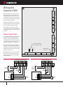
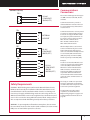
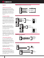
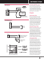
NUFLO™
Part No. 30165024, Rev. A
Scanner® 2200 EFM
QuickStart
A Quick Reference on Mounting,
Wiring, and Configuring the
Scanner 2200 EFM
For complete instructions,
see the Scanner 2200 User Manual
(Part No. 9A-30165030) and the
ModWorX™ Pro Software User Manual
(Part No. 9A-30165025).
Installing the
Scanner 2200 EFM
Mounting Instructions
To install the NuFlo Scanner 2200 EFM, perform the following steps:
1. Mount the Scanner to a flat, vertical surface using the
brackets, or bolt to a 2-in. pipe using the pole-mount
hardware provided.
2. Install process tubing between the orifice run and the
manifold, making sure that the upstream pressure tap
is connected to the high-pressure manifold port and
the downstream pressure tap is connected to the lowpressure manifold port. Slope all piping at least 1-inch
per linear foot to avoid trapping liquid.
3. Use a suitable compound or tape on all threaded process connections.
4. Position all shutoff and bypass valves so they are
accessible from the front of the instrument.
5. Check the manifold for leaks.
Important—Due to the weight of the instrument and
the potential for vibration in pipeline installations, direct
mounting the Scanner 2200 to a manifold is not recommended. A remote mount is recommended for instrument
stability.
TB3
TB2
Field wiring enters the Scanner 2200
EFM through the conduit hubs in the
bottom of the enclosure and connects
to terminal blocks on the circuit assembly, and the DC power supply/charger or
the solar charge controller.
TB4
Thirteen terminal blocks are arranged
along the bottom and side edges of the
circuit assembly, as shown at right.
TB5
The numbers printed on the charge
controller and DC power supply indicate
the order in which connections should
be made.
PULSE IN 2 TURBINE PULSE IN 1 TURBINE
POWER IN &
CONTACT IN 2 IN 2 CONTACT IN 1 IN 1 RADIO POWER OUT
TB1
Wiring the
Scanner 2200
1-5V
TB9
TB10
TB11
ANALOG OUT
ANALOG INPUT 1 & 2
RTD
SOLAR POWER
DC POWER
BATTERY
LOAD
2
3
4
5
6
+
-
+
-
+
-
7
+
SOLAR
PANEL,
12 V
GND
SCANNER 2200 BOARD
12V
Battery
GND
SCANNER 2200 BOARD
-
+
-
RADIO
POWER
RADIO
OUT POWER
RADIO
OUT POWER
2
BATTERY
BATTERY
LOAD
4
3
2
1
6
5
+
-
+
-
+
-
Sealed
Flooded
12V
Battery
-
TB1
TB1
-
J5
+
-
-
+
+
DIGITAL OUT 1 & 2 PORT1 RS-485
SOLAR
GND
1
TB13
CHARGE CONTROLLER
DC POWER SUPPLY/CHARGER
INPUT
TB12
PORT 2
RS-232
Lithium battery
connection
4-20mA
PORT2
RS-485
J4
1-5V
Wiring diagrams for DC power and solar
power are provided below. For other
power options, see the Scanner 2200
EFM User Manual.
16 to 28
VDC
4-20mA
PORT 2
RS-485 / USB
J3
TB6
Analog input jumpers
(see page 4 for details)
When the Scanner is powered externally,
the internal lithium battery pack (two
“D” batteries in series) provides backup
power and should not be disconnected
from the J5 connector.
TB7
The Scanner 2200 EFM can be powered
externally with a 16 to 28 VDC power
supply or a 12-VDC solar panel using
an integral charge controller and a lead
acid battery. The Scanner 2200 supports
batteries rated up to 33 amp-hours.
TB8
Power Connections
+
+
-
+
-
RADIO
POWER
Communications
Connections
COM PORT 1 (RS-485)
TB13
COM
COM
A
A
B
B
RS-485
COM DEVICE
(RADIO, ETC.)
Communications Port 1 provides a
dedicated RS-485 connection that can
be used simultaneously with Communications Port 2.
COM PORT 2
TB8
USB
ACTIVE
USB
ACTIVE
B
B
A
A
COM
EXTERNAL
USB PORT
COM
TB7
B
B
A
A
COM
COM
RS-485
COM DEVICE
(RADIO, ETC.)
TB6
TXD
TXD
RXD
RXD
SLP
SLP
COM
COM
RTS
RTS
CTS
CTS
The Scanner 2200 supports three types
of COM connections: RS-485, RS-232,
and USB.
RS-232
COM DEVICE
(RADIO,
MODEM, ETC.)
Safety Requirements
CAUTION—All field wiring must conform to the National Electrical Code,
NFPA 70, Article 501-4(b) for installations within the United States or the
Canadian Electric Code for installations within Canada. Local wiring ordinances may also apply. All field wiring must have a wire range of 22 to 14
AWG and terminal block screws must be tightened to a minimum torque of
5 to 7 in-lbs. to secure the wiring within the terminal block. Only personnel
who are experienced with field wiring should perform these procedures.
Communications Port 2 is factory wired
to support an external USB connector,
but it can also support RS-485 and RS232 inputs. Any of three terminals can
be used to connect a device to Port 2:
TB6—RS-232 communications
TB7—RS-485 communications
TB8—USB communications
While multiple devices can be wired
to Port 2 simultaneously, the Scanner
2200 communicates with only one
device at a time. When multiple devices
are connected, USB communication
(TB8) has priority over RS-232 (TB6),
which has priority over RS-485 (TB7).
Example:
A radio is connected to TB6 and a user
connects a laptop to the external USB
connector (TB8) to download data.
When the Scanner 2200 detects the
USB connection, communications
with the radio (TB6) are temporarily
suspended. When the USB cable is
disconnected from the external USB
connector, radio communications via
TB6 resume.
The sleep pin on TB6 is an open drain
transistor output that is intended for
use with radios that incorporate a hardware line for power management.
For information on radio control
capabilities, see the Radio Power
Output wiring diagram on page 5 and
Configure Radio Communications on
page 10.
WARNING—To prevent ignition of hazardous atmospheres, do not remove
the cover while circuits are alive. Under normal conditions, the Scanner 2200
EFM poses no hazard when opened in a safe area.
3
TEMPERATURE INPUT (shown with 4-wire interface)
TB11
Temperature Input (TB11)
Pulse Input (TB3/TB5)
Two pulse inputs provide optically
isolated inputs for high-amplitude pulse
(frequency) signals, which includes signals from a turbine meter equipped with
a preamplifier or signals from a PD meter
(via contact closure).
4
RED
I+
RED
IN−
RETURN
IN+
SIGNAL
PWR
POWER
1-5 VDC
TRANSMITTER
J3 / J4
1-5V
IN−
TB10
IN+
PWR
IN−
ANALOG 2
ANALOG 2
TB10
IN+
−
PWR
+
4-20 mA
TRANSMITTER
J3 / J4
IN−
4-20 mA
IN+
PWR
Shunt Resistance: 249 ohms
TURBINE INPUT (TB2 AND TB4)
TB2 / TB4
+
RED
A
BLACK
B
TURBINE
MAGNETIC
PICKUP
PULSE INPUT / RELAY CONTACT
TB3 / TB5
+
+
–
A differential pressure flow run and
two turbine runs can be monitored and
logged simultaneously.
RTD+
ANALOG INPUT (1-5V or 4-20 mA TRANSMITTER)
Turbine Inputs (TB2/TB4)
The Scanner 2200 EFM provides two
turbine inputs that accept a turbine
flowmeter input signal generated by a
magnetic pickup. The Scanner 2200 can
be configured to use this signal to calculate and display instantaneous flow rates
and accumulated totals.
RTD+
ANALOG 1
The position of a jumper on the board
determines whether the input circuit is
configured for a 1-5V signal or a 4-20 mA
signal. No resistors are required. Jumper
J3 determines the signal type for analog
input 1. Jumper J4 determines the signal
type for analog input 2.
WHITE
I+
ANALOG 1
The Scanner can be used to power a
transmitter only when the Scanner is
externally powered. The output voltage
equals the input voltage less 0.25 VDC,
and is limited to 20 mA.
RTD −
TB3 / TB5
+
–
The Scanner 2200 EFM provides two
analog inputs that can be configured for
a 1-5 V, 0-5 V or 4-20 mA signal. They can
receive readings from a static pressure,
differential pressure, or temperature sensor for any type of calculations, and they
can be used to log measurements from
any device with a 1-5 V, 0-5 V or 4-20 mA
output.
RTD−
–
Analog Input (TB10)
WHITE
I−
I−
A 4-wire, 100-ohm platinum 0.00385
OHM/OHM°C RTD is recommended for
performing orifice gas and compensated
liquid calculations or gas turbine calculations, though a 2- or 3-wire RTD may
prove functional. See the Scanner 2200
EFM User Manual for 2-wire and 3-wire
diagrams.
–
Inputs
PULSE INPUT
(3 TO 30 VDC)
RELAY
CONTACT
Pulse Input (TB3/TB5) cont’d
DIGITAL OUTPUT
PULSE READOUT
DEVICE
DIG
OUT 2
TB12
DIG
OUT 1
POWER
SUPPLY
5 to 30 VDC
Resistor may be included in
the readout device. Size the
resistor to limit current to 60 mA.
RADIO POWER OUTPUT
RADIO OUT
TB1
+
+
−
−
RADIO
POWER
ANALOG OUTPUT
TB9
+
ANALOG READOUT
(Resistor may be
included.)
LOAD RESISTANCE (OHMS)
POWER SUPPLY
8-30 VDC
800
200
OPERATING
REGION
0
8
12
24 30
LOOP SUPPLY VOLTAGE (VDC)
The Scanner 2200 can calculate flow
from no more than two frequency inputs
at a time, so if a turbine input is used,
only one other frequency input may be
received simultaneously. Each of the two
frequency inputs can be a turbine input,
a pulse input, or a contact input.
Outputs
Digital Output (TB12)
The Scanner 2200 supports two solidstate digital outputs that are configurable as either a pulse output or an alarm
output. Because the circuit is isolated,
it can be used in conjunction with any
other feature on the Scanner 2200. The
maximum rating of the digital output
circuit is 60 mA at 30 VDC. Maximum
frequency is 50 Hz. For reduced power
consumption, turn the digital output
feature off when it is not in use.
Radio Power Output (TB1)
When the Scanner 2200 is used to power
a radio, a user can conserve power by
controlling the power output to the
radio. To enable this control, the radio
power must be wired to TB1 and the
radio power settings must be configured
in ModWorX Pro software. The maximum
voltage rating of the TB1 circuit is 30V.
The maximum current rating is 1A. See
Configure Radio Communications on
page 10 to configure radio power settings.
Analog Output (TB9)
The 4-20 mA linear current output can
be configured with ModWorX™ Pro
software to represent any parameter
in the holding registers. This output requires a two-conductor cable to be connected to an 8 to 30 VDC power supply
(voltage required is dependent on loop
resistance) and an analog readout device
to be located in the remote location.
The graph at left shows the minimum
voltage required to power the instrument for a given loop resistance. In
addition, the mathematical relationship
between loop voltage and load resistance is given. For example, if a power
supply voltage of 24 volts is available to
power the current loop, the maximum
load resistance would be 800 ohms.
5
Navigating the ModWorX™ Pro Interface
Main Display Screen
Dedicated button for quick and easy downloads
Four task-based menus
simplify navigation
The ModWorX Pro installation CD provided
with the instrument loads the ModWorX Pro
interface software for configuring and operating the Scanner 2200.
The Main Display screen (at left) is the control
center for the Scanner 2200 and provides quick
and easy access to the most commonly
performed tasks. From this screen, the user can:
• view real-time totals and flow rates, input
data, and system information
• download data
• access configuration, calibration, and flow
run/turbine maintenance menus
• get quick answers to task-specific questions
with links to user documents
Documentation for quick reference
Controls for all commonly performed tasks are conveniently grouped under four
menus near the top of the Main screen. Menus are named for the functions they
support: Calibrate Inputs, Maintain Flow Run, Maintain Turbine, or Configure.
6
Calibrate Inputs Menu
From the Calibrate Inputs menu, a user can calibrate differential pressure, static pressure, process temperature, and analog inputs. The
user can load a factory calibration, load a previous calibration, or enter new calibration points.
1 Select the task you
want to perform.
Then select the parameter
you want to calibrate.
2 Click Acquire Point to enter a new
calibration point and enter the applied
calibration value at the prompt.
Or click Load Calibration From... to load
the data from a factory calibration or
previous calibration.
Click on Change Task to
select a new parameter
or a new calibration task.
3 The measured value
can be viewed with or
without a trend graph.
Repeat Step 2 to enter
additional calibration
points.
4 Click Save Changes to
save the New Calibration
values to memory.
5 Click Exit
Maintenance Mode
to resume live data
readings.
Maintenance Mode
When a user enters a menu in which parameter changes
affect volume calculations, the Scanner 2200 is placed in
“Maintenance Mode.” This locks the input sensor readings at
their current values. When the user exits “Maintenance Mode,”
the inputs are unlocked.
7
Maintain Flow Run Menu
From the Maintain
Flow Run menu, a
user can change an
orifice plate size,
cone meter or
averaging pitot
tube parameters,
cone meter factors,
steam properties, or
gas composition.
1 Select the task you
want to perform.
2 Enter new parameters in the fields
provided.
Or click on Copy From Current to load current
parameters.
3 Click Save Changes to save the new
parameters to memory.
4 Click Exit
Maintenance Mode
to resume live data
readings.
Tasks will vary with
the flow calculation
method used.
Click
Change Task to
select a new maintenance task.
Maintain Turbine Menu
From the Maintain
Turbine menu, a
user can change the
K-factor or select
a different turbine
meter.
The user can enter a
linear K-factor or a
multi-point calibration factor (1 to 12
points allowed).
Click Change Task to
select a new turbine
meter or a new
maintenance task.
8
1 Select the task you
want to perform.
2 Select a new meter or enter a new
K-factor using the fields provided.
3 Click Save Changes to save
the new selections to memory.
4 Click Exit
Maintenance Mode
to resume live data
readings.
Configure Menu
From the Configuration
menu (right), a user can access
every setting required to
perform the initial setup for
the Scanner 2200.
1 Set the instrument date and
time.
2 Establish archive settings
• parameters to be logged
• contract hour
• interval period for saving logs
The Configure Flow Run 1 screen below
shows configuration settings for an
AGA-3 gas run. Required parameters will
vary, depending on the flow calculation
method selected (step 6).
For information on configuring a steam
flow run, see the ModWorX™ Pro User
Manual.
If a liquid turbine input will be used in
addition to a compensated gas run,
click on Turbine Input 1 for configuration options.
3 Configure flow run
parameters (as shown below).
4 Set the calculation period.
5 Set the units of measurement
used for volume and rate.
6 Click “Change” to select the flow
calculation method and fluid property
calculation method to be used.
7 Click “Change Plate” to
specify plate parameters.
8 Specify pipe parameters.
9 Enter base conditions
specific to the location.
10 Click “Change Composition”
to specify the gas composition.
(Percentages must total 100%.)
11 Click OK to save the new
selections to memory.
9
Configure Radio Communications
When the Scanner 2200 is connected to a
communications device such as a radio,
power consumption can be minimized by
configuring radio settings.
To control power to the communications
device, the device must be wired to the
Power Out terminal block (TB1) of the
Scanner 2200 .
If a radio has a hardware line for power
management, it can be wired to the sleep
output on TB6 to control sleep functions.
ModWorX Pro is used to configure the sleep
functions (see Step 4 below).
2 In the Port 2 Settings
section, change the Port Usage
field to Modbus Slave with Radio
Controller.
3 In the Radio Settings section, configure
the power mode as “always on” for continuous
power, or “on/off times” to select the time of day
for turning the radio off and on. If “on/off times”
is used, enter “power on” and “power off” times
by clicking the Edit buttons.
4 To enable sleep control, select “Yes” in the
Enable Sleep Control field. Specify an “awake”
time period and a “sleep” time period by clicking
the Edit buttons.
The sleep cycle period will be automatically
displayed in a read-only field.
10
1 From the Configuration Menu,
click on the Communications tab.
Download Screens
To download data, simply press
the Download button and
select the range and type of
files to be downloaded. Daily
and interval logs can be viewed
or printed as a table or a trend
graph.
1 Click on the red
Download button to
download log data.
Each log type and setting type is
displayed under a separate tab.
2 Select the range of
data, the type of logs,
and any additional
settings to be included
in the report. Then click
Download Now.
3 Downloaded data will appear in
a table as shown. Click one of these
buttons to:
• export data
• print the tabular data
• view and/or print a trend graph
Export formats:
.cfx (Flow-Cal®)
.ANA, .VOL, and .EVT (PGAS®)
.pdf, .xls, .rtf, .csv, and .html
4 The trend view offers two methods
of navigation:
View all downloaded data
(gray box shows range
of data displayed in
bottom graph).
Select the parameter
you want to view.
(1) Use the scroll bar to move the trend
line left or right. The data point that intersects this vertical record index (white
dotted) line marks the record being
read; the values of all parameters in the
record appear in the table at left. Values
in the table update automatically as the
intersecting data point changes.
(2) Move the mouse to guide the
cursor along the trend line. The cursor
will snap to the nearest data point. The
corresponding parameter, date and
time stamp, and parameter value will
appear in a pop-up box on the screen.
11
Accessing User
Documents
Electronic user documents including a
hardware manual, software manual, this
quick start guide, and other support documentation are embedded in the ModWorX
Pro software. With the click of a button,
they will open inside the ModWorX Pro
viewing window for quick reference.
1 Click Help >
User Manuals
or click
User Manuals tab
User documents can be accessed two ways:
• Click the User Manuals tab at the bottom
of the screen.
• Click the Help menu at the top of the
screen and select User Manuals.
Select your Scanner product to open a list
of links to user documents supporting that
product.
2 Select your product.
To return to the Select Your Product screen
to select a different document, click the
Home button.
To restore the view of ModWorX Pro
controls, click the Device Interface tab at
the bottom of the screen.
3 Click on the link for
the desired document.
4 Click the Device
Interface tab to restore
view of ModWorX Pro
controls.
5569.0501
[email protected]
INDIA
Part No. 9A-30165029, Rev. 02
KENYA