1
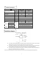
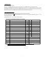
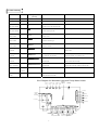
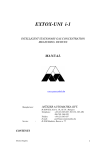
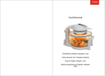
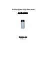
Air Source Heat Pump Water Heater User Manual Monobloc Type (L1 Series) Table of Contents Caution ---------------------------------------------------------------------------------------------------- 3 Technical Parameter---------------------------------------------------------------------------------------4 Installation diagram ------------------------------------------------------------------------------------ 4 Wire controller instruction -------------------------------------------------------------------------------5 Trouble shooting -------------------------------------------------------------------------------------------8 Wire diagram -----------------------------------------------------------------------------------------------8 2 CAUTION Do not climb on the unit or try to move it when Keep out of the reach of children do not let Installed . children playing near the unit. Do not insert fingers or anything into air inlet / Important: outlet. The rotating fan maybe cause serious adheres to it maybe lead to fire or incident. shocks. If an abnormality (smell of burning…) occurs, Do not clean the machine with water. stop the Unit, unplug or switch off the power. Water will go into the unit and destroy system. Do not connect / unconnect the unit when Keep plug clean, any dirtiness electric Do not draw the power supply cable . When it is running; Please handle after all the buttons in hand don’t connect the plug to avoid any risk OFF. or damage. Do not touch the plug with wet hands, It will Once find leaves or other little particles blocking caused electric shock. the air inlet, please pick them out of machine At stormy weather, cut off power to avoid any after shut off the power. damaged caused by the lightning Check the compatibility of the network with the data on the nameplate of machine before installation. Any disinfection systems such as electrolysis, chemical … are not recommended for a running status. 11 They are should be used before systems running. 3 Technical parameter YASL1-28HL YASL1-38HL W 2800 3800 BTU 9554 12966 V/PH/HZ 220V/1/50HZ 220V/1/50HZ KW 825 1085 A 4 4.9 L/h 95 140 Model Heating Capacity Power Supply Input Power Running Current Hot Water Generated Water Tank Volume L 150 / 200 / 260 / 300 / 400 / 500 Thermostat Factory Setting °C 60 Maximum Outlet Water Temp. °C 65 Compressor Quantity Noise dB(A) H Dimension W Net Weight Gross Weight 1 47 48 1300 / 1430 / 1630 / 1800 / 2170 / 2430 mm D Weight 1 570 / 640 / 640 / 640 / 640 / 700 570 / 640 / 640 / 640 / 640 / 700 kg 62 / 75 / 81 / 102 / 119 / 133 72 / 90 / 96 / 120 / 136 / 155 Installation diagram The monobloc heat pump water heater has compact and grace shape with built-in water tank, has the simplest installing, that is only need to connect power supply, water pipe or/ and inlet / outlet air duct. The monobloc heat pump water heater also provides cool air (by-products) freely when it heating the water,meantime promote ventilation in room through air duct, and cool down air temp. for reserve goods/vegetables,etc. The monobloc heat pump could connect solar system or/ and boiler/ gas system to show perfect performance of heating room meantime bather water even in coldest winter. Note: please install a reducing valve on the top or beside the water outlet for pressure discharging and protecting water tank. 4 Controller Displayer instruction Feature 1. Displayer shows ambient temperature from ranged - 30 ℃ to 80℃. 2. Mode: Heat pump hot water and Electric heating mode. 3. Display water temperature and setted water temperature. 4. Protection function: give an alarm automatically when trouble occur. 5. Automatical disinfection function for water tank every week. 6. Electric heating will running automatically during defrosting. 7. Clock display function. 8. Memory function: Keep information when machine was shut off. Button Power on When power on, the displayer shows in full screen within 3 seconds then enter into running status. botton Under running state, press Under standby status, press "▲", "▼" to enter the standby state, displayer shows the inlet/out water temp., timer status and clock. to enter the running status. displayer shows the inlet/ outlet water temp, timer status and clock. button Be used for setting and adjusting parameter ,timer, time and clock. Under clock setting status, press "▲"or Under timer status, press, press "▲"or "▼" to adjust number of hour and minute; "▼" to adjust the setted hour and minute; Under usual status, (except the clock and timer status), press "▲"or Under the parameter adjusting of standby status, press "▼" to adjust parameter( parameter 0-11). and ELEC at same time for 5 seconds to lock the button, do it once again to exit the lock status. "CLOCK" button When power on, the machine enters clock setting status with “88.88” flashing. Press "CLOCK" again to enter hour setting status, once again for minute setting status. Press CLOCK one more time to exit the clock setting parameter. Under clock setting status, press "▼" to adjust the relattive time. The button "TIMER" is not available when machine is under clock setting status. Under timer status, press CLOCK to cancel the timer. 5 "▲", "TIMER" button Be used for geting into timer status. Press "▲", "▼" button to choose time for power on and power off, press "TIMER" again to confirm the chosen mode. Except the clock setting status, press the button to enter the timer status, press "▲", "▼" to choose timed power on or power off, then press "TIMER" to confirm the chosen mode, press "TIMER" to enter the setting status for timed hour and minute, to exit this timer setting, with one more press on "TIMER" under relative timer status, press CLOCK to cancel the timer. "ELEC.HEATING" button Press the button to enter the mode of electric heating, to browse and setting of the parameter. Under the standby status, press and "ELEC.HEATING" button at same time to enter parameter setting status. Press "▲", "▼" button to adjust parameter. Under other status, press "▲", "▼" button to browse parameter. The shows and adjustable parameter on displayer Parameter Meaning Scope Default Note 0 The setting for water temp in tank Ta1 10-70℃ 55℃ Adjustable 1 The temp difference setting to restarting Ts6 2-15℃ 5℃ Adjustable 2 The temp for exiting elecheater Ts2 10-90℃ 55℃ Adjustable 0-90 30 t*5min 60-90℃ 70℃ Adjustable 3 Lagtime for Electric heating t1 4 The disinfection temp of elec heater(weekly)Ts3 5 The durative time for disinfection t2 10-90min 30min Adjustable 6 The cycle for defrosting in heating mode t3 30-90min 4-5min Adjustable 7 The temp point to enter defrosting in heating mode TS4 -30-0℃ -7℃ Adjustable 8 The temp point to exit defrosting in heating mode Ts5 2-30℃ 13℃ Adjustable 9 The time exiting defrosting in heating mode T4 1-12min 8min Adjustable 10 The adjustment for electronic expansion valve 0/1 1 11 The superheat of target -20℃-20℃ 5 12 The step amount to adjust the electronic expansion valve 10-50 35 A The bottom temp of water tank T1 -9 ~ 99℃ actual tested date , display P1 if fault B The top temp of water tank T2 -9 ~ 99℃ actual tested date , display P2 if fault C Coil temp T3 -9 ~ 99℃ actual tested date , display P3 if fault D Return air temp T4 -9 ~ 99℃ actual tested date , display P4 if fault E Exhaust temp T5 -9 ~ 99℃ actual tested date , display P5 if fault F The step amount of electronic expansion valve 0 ~ 50 N*10 0 manual Adjustable 35N*10(parameter 0=0 is valid) Note: All these above parameter were settled in factory , please do not alter it at random. Note: temperature protection failured can be restored automatically. 6 1 automatic Trouble shooting Trouble Code Reason Running and trouble Solution polit lamp Standby Status Black out / / Running Light / / Bottom of water PP1 ☆● The short circuit or disconnection tank sensor trouble Top of water Of the sensor on the bottom of tank. PP2 ☆☆● The short circuit or disconnection of the tank sensor trouble Coil ☆☆☆● The short circuit or disconnection of the sensor trouble ☆☆☆☆● The short circuit or disconnection of the sensor trouble PP5 pressure Check or replace the sensor sensor for the back gas ☆☆☆☆☆● The short circuit or disconnection of the sensor trouble High Check or replace the sensor sensor of coil PP4 Exhaust Check or replace the sensor sensor on the top of tank PP3 Return air Check or replace the sensor Check or replace the sensor sensor for exhaust EE1 ☆☆☆☆☆☆● System pressure is too high To check if the water temp is too high or if there is protection Low water in tank pressure EE2 ☆☆☆☆☆☆☆● protection Overheat EE5 ☆☆☆☆☆☆☆☆☆☆● EE6 ☆☆☆☆☆☆☆☆☆☆☆● protection Exhaust temp protection Defrosting Defrosing The system pressure is too low/ capacity Lack of refrigerant, to check if there is any leakage, or expansion valve blocked change the capillary or expansion valve. The switch for overheat protection is The water temp in tank is too high. Cut off the elec disconnected heater to down the water temp. The switch for exhaust protection is To check if the system is lack of refrigerant, if the water disconnected temp in tank is too high, if there is water in tank Always flashes / / indicator Communication EE8 No flash There is no communication between the trouble To check if the controller is connected well with PCB PCB and remote controller Wire Diagram for Monobloc type Heat Pump Water Heater Water Pump Four-Way High Valve Wind 06 08 07 3 4 Medium Low Wind Wind Running Pilot Lamp 10 09 5 Electronic Expansion Valve 6 11 7 41 2 1 Compressor 39 37 35 02 32 13 03 14 15 16 17 18 19 20 21 22 23 24 25 26 27 28 29 30 N Line Transformer Input Junior 12 31 Self-Check Bottom Low Voltage Transformer Overheating Emergency Switch Secondary Protection WaterSwitch Phase Sequence Time High Voltage Protection Flow demagnification Switch Communication Port Switch 7 Exhaust Temp. 34 33 12 Under-part Temp 36 19 01 Upside Temp. 38 05 04 39 L line Input Coil Temp. 40 Electronic Heating Return Air Temp.