1
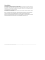
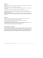
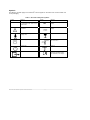
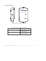
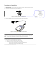
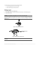
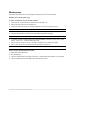
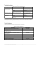
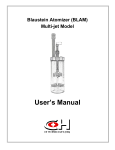
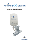
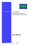
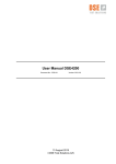
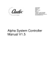
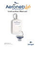
Instruction Manual © 2004 Aerogen, Inc. Part No. AG-AL1010 Rev. C Table of Contents Introduction ........................................................................... 3 System description ................................................................ 4 Warnings .......................................................................... 5 Cautions ........................................................................... 5 Electromagnetic Susceptibility.......................................... 5 Symbols ........................................................................... 6 Controls and indicators..................................................... 7 Assembly and installation ...................................................... 8 Adding Liquid ........................................................................ 9 Functional test ..................................................................... 10 Maintenance........................................................................ 11 Troubleshooting................................................................... 12 Order Numbers.................................................................... 12 Specifications ...................................................................... 13 Physical.......................................................................... 13 Environmental ................................................................ 13 Performance................................................................... 13 Power............................................................................. 13 List of Figures ® Figure 1: Aeroneb Lab ......................................................... 4 Figure 2: Aeroneb® Lab controls and indicators ..................... 7 Figure 3: Connecting filler cap to nebulizer unit. .................... 8 Figure 4: Connecting nebulizer unit to control module........... 8 Figure 5: Filling the nebulizer unit.......................................... 9 Figure 6: Maximum fill indication point................................... 9 List of Tables Table 1: Aeroneb® Lab System symbols................................ 6 Table 2: Aeroneb® Lab control/indicator functions ................. 7 Table 3: Aeroneb® Lab Troubleshooting.............................. 12 Table 4: Aeroneb® Lab parts list……………………………….12 Aeroneb® Lab Nebulizer System Instruction Manual 2 Introduction ® The Aeroneb Lab Nebulizer System is a nebulizer system that is intended to aerosolize solutions for pre-clinical testing. It is not intended for use with humans. The Aeroneb® Lab Control module operates from an AC/DC adapter, with the option of being directly powered from any automated test equipment providing 9 volts DC. This can enable the timing of aerosolization based on programmed criteria. ® The Aeroneb Lab is a latex-free nebulizer system that incorporates Aerogen’s proprietary OnQ™ Aerosol Generator for aerosolization. ® Note: The Aeroneb Lab, utilizing OnQ™ Aerosol Generator technology, has been utilized to aerosolize a broad range of liquid formulations, including suspensions and proteins. However, the ability to effectively aerosolize a novel formulation or chemical entity can only be determined through direct testing, and is the responsibility of the device user. Aeroneb® Lab Nebulizer System Instruction Manual 3 System description The Aeroneb® Lab (Figure 1) includes the following components: Nebulizer unit (containing the OnQ Aerosol Generator and filler cap), control module, control module cable, AC/DC adapter and DC cable. Filler Cap 1. Nebulizer Unit (Including Filler Cap) 2. Control Module 3. Control Module Cable 4. AC/DC Adapter 5. DC Cable Figure 1: Aeroneb® Lab The nebulizer unit holds up to 10mL of liquid. The nebulizer unit is translucent to allow visual monitoring of liquid levels and aerosolization. Within the nebulizer unit is an OnQ Aerosol Generator, which consists of a domed aperture plate with precision-formed holes that control the size of the aerosol droplets, and a vibrational element whose micro-pumping action aerosolizes liquid. Gravity brings the liquid in contact with the aerosol generator, where the liquid is drawn through the aperture plate and converted into an aerosol. The control module can be powered by applying a 9V DC signal from an external DC voltage source to the DC cable; this cable is then connected to the control module. Alternatively power can be supplied from the AC/DC adapter. The control module also includes a cable that attaches to the nebulizer unit. The control module includes visual indicators that display power on status, and fault condition status. Aeroneb® Lab Nebulizer System Instruction Manual 4 Warnings Read and study all instructions before using the Aeroneb® Lab. Only trained personnel should operate the device. For pre-clinical use only. It is not intended for use with humans. Do not use in the presence of a flammable anesthetic mixture combined with air or with oxygen or nitrous oxide. To avoid the risk of fire, do not use in the presence of flammable substances. Assemble and perform a functional test according to the instructions in this manual before use. If this equipment is not used in a manner specified in this manual, the protection provided by the equipment may be impaired. The ability to effectively aerosolize a novel formulation or chemical entity while maintaining the integrity of this entity can only be determined through direct testing, and is the responsibility of the device user. Cautions To avoid mechanical or electrical damage, do not drop the nebulizer unit or the control module. Disconnect nebulizer unit from control module before cleaning. Do not immerse in water or autoclave the control module, cables or AC/DC adapter. Use only with components specified by Aerogen. Inspect all parts before use, and do not use if any parts are missing, cracked or damaged. In case of missing parts, malfunction or damage, contact your Aerogen representative. Do not use or store outside of specified environmental conditions. Electromagnetic Susceptibility This device meets the requirements for Electromagnetic Compatibility as defined by European Directive 89/336/EEC relating to Electromagnetic Compatibility. This includes immunity to radio frequency electric fields and electrostatic discharge, in addition to the other applicable requirements of the standard. Compliance with EMC standards does not mean a device has total immunity; certain devices (cellular phones, pagers, etc.) can interrupt operation if they are used near the equipment. Aeroneb® Lab Nebulizer System Instruction Manual 5 Symbols The following symbols apply to the Aeroneb® Lab and appear on the back of the control module and on the packaging: Table 1: Aeroneb® Lab System symbols Symbol AL-YYXXXX Meaning Symbol Serial number, where YY is the year of manufacture and XXXX is the serial number. Attention, consult documents. Meaning ~ Control Module Output – A.C. voltage. Control Module Input – D.C. voltage. accompanying Degree of protection against dripping water. Fragile, handle with care. Class II equipment per IEC 610101. Storage temperature limitations –20 °C to +60 °C. On/off power. Keep dry. Output Compliance with the European Directives 89/336/EEC (EMC) and 73/23/EEC (Low Voltage). Aeroneb® Lab Nebulizer System Instruction Manual 6 Controls and indicators FOR PRE-CLINICAL USE ONLY NOT FOR HUMAN USE Figure 2: Aeroneb® Lab controls and indicators Table 2: Aeroneb® Lab control/indicator functions Control/indicator Function Amber Warning LED When illuminated, indicates nebulizer is disconnected or faulty connection. Green Power/delivery LED When illuminated, indicates that power is supplied and that the unit is aerosolizing. Aeroneb® Lab Nebulizer System Instruction Manual 7 Assembly and installation 1. Clean the nebulizer unit as described in the maintenance section of this manual prior to first use and between uses. 2. Insert the filler cap into the opening on the nebulizer unit. Figure 3: Connecting filler cap to nebulizer unit. 3. Connect the nebulizer unit to the control module using the control module cable Figure 4: Connecting nebulizer unit to control module. NOTE: To ensure uninterrupted operation of the Aeroneb Lab, secure power and control module cables so they cannot become disconnected during treatment. Ensure all cables are routed safely. NOTE: To ensure proper nebulization, maintain the nebulizer in an upright position. 4. When powering the control module using the DC cable: • Insert one end of the DC cable into the control module. • Connect the other end to a 9V DC power source ensuring: ® o The wire with the red sheath is connected to a positive terminal. o The black wire is connected to a negative terminal. Aeroneb Lab Nebulizer System Instruction Manual 8 Deleted: 5. When powering the control module using the AC/DC adapter: • Insert the adapter jack into the control module. • Plug the adapter plug into wall socket mains. Adding Liquid 1. Open the filler cap tab on the nebulizer unit. 2. Use a prefilled ampoule or syringe to add liquid into the filler port of the nebulizer (Figure 5). 3. Close the filler cap tab. CAUTION: To avoid damage to the nebulizer unit, do not use a syringe with needle. The maximum capacity of the nebulizer unit is 10 mL. Do not fill the nebulizer unit beyond the maximum fill indication point (Figure 6). The underside of the filler cap represents maximum fill indication point. Figure 5: Filling the nebulizer unit MAXIMUM INDICATION FILL POINT Figure 6: Maximum fill indication point Note: Liquid can also be added in this manner during nebulization. nebulization. Aeroneb® Lab Nebulizer System Instruction Manual 9 This does not interrupt Functional test To perform a functional test of the Aeroneb® Lab before each use or to verify proper operation, follow these steps: 1. Visually inspect the device for cracks or damage and replace if any defects are visible. 2. Pour 0.5 mL of sterile water or normal saline into the nebulizer unit. 3. Connect the nebulizer unit to the control module, connect the control module to the power source. 4. Verify that the green power light is on. Ensure that aerosol is visible. 5. Disconnect power to turn the system off. 6. Discard any remaining liquid before next use. Aeroneb® Lab Nebulizer System Instruction Manual 10 Maintenance This section describes how to clean, sterilize, and inspect Aeroneb® Lab components. Nebulizer unit (including filler cap). To clean unit between uses for the same subject 1. Disconnect the control module and cable from the nebulizer unit. 2. Remove the filler cap from the nebulizer unit. 3. Clean parts with warm water and mild liquid detergent. Rinse thoroughly and air dry. CAUTION: Do not use abrasive or sharp tools to clean the nebulizer unit. 4. Check for cracks or damage, and replace if any defects are visible. 5. Place the disassembled components into appropriate sterilization wrapping. CAUTION: Do not reassemble parts prior to autoclaving. 6. To sterilize, autoclave wrapped parts using steam sterilization pre-vacuum cycle, 132°C -135°C (270°F - 275°F) for 3 - 4 minutes with drying cycle. 7. Prior to next use, check for cracks or damage, and replace if any defects are visible. 8. Prior to next use, perform a functional test as described in this manual. NOTE: It is recommended that the device be cleaned after each use to ensure proper nebulization Control module, AC/DC adapter and cable. 1. Wipe clean with a damp cloth. 2. Do not autoclave. 3. Check for exposed wiring, damaged connectors, or other defects and replace if any are visible. 4. Perform functional test as described in this manual before re-use. Aeroneb® Lab Nebulizer System Instruction Manual 11 Troubleshooting Table 3: Aeroneb® Lab Troubleshooting If this happens: It could mean: Try this: The indicator lights, but aerosol is not visible. No liquid in nebulizer unit. Refill liquid through filler cap in the nebulizer unit (see Adding Liquid). Nebulizer unit has not been properly cleaned. Clean nebulizer unit (see Maintenance). It may be time to replace the nebulizer unit. Refer to Aeroneb® Lab parts list. Indicator does not light. There is no power to the system. Verify that AC/DC adapter is securely attached to control module. Longer than expected treatment time. Nebulizer unit has not been properly cleaned. Clean nebulizer (see Maintenance). The nebulizer unit may need replacement. Refer to Aeroneb Lab parts list. ® If these suggestions do not correct the problem, discontinue use of any device that is, or appears to be damaged or not operating properly and contact your local Aeroneb® Lab product representative. Order Numbers Table 4 lists the Aeroneb Lab order numbers (see Figure 1 for pictures) Table 4: Aeroneb® Lab parts list. Description Order Number ® AG-AL7500 ® AG-AL7000 ® Aeroneb Lab Nebuliser Unit, Autoclavable, Standard (4.0 – 6.0 VMD) particle size. AG-AL1000 Aeroneb® Lab Nebulizer Unit, Autoclavable, Small (2.5 – 4.0 VMD) particle size. AG-AL1100 Aeroneb® Lab DC Power Cable AG-AL2000 Aeroneb Lab Control Module (includes DC cable) Aeroneb Lab Control Module (includes AC/DC adapter) Control Module detachable cable (replaceable) AG-AP1085 AC/DC Adapter AG-AP1040-XX* Filler Cap (pack of 5) AG-AP1030 ® Aeroneb Lab Instruction Manual AG-AL1010 *Consult your local representative for the order code extension specific to your country and for pricing. Aeroneb® Lab Nebulizer System Instruction Manual 12 Specifications Physical Nebulizer unit dimensions: 45 mm H x 50 mm W x 50 mm D (1.77 in. H x 1.97 in. W x 1.97 in. D). Control module dimensions: 33 mm H x 75 mm W x 131 mm D (1.3 in. H x 2.9 in. W x 5.2 in. D). Control module cable: 1.8 m (5.9 ft.) long. Nebulizer unit weight: 25 g (0.88 oz.) nebulizer unit and filler cap. Control module weight: 178 g (6.3 oz.), including cable. Nebulizer unit capacity: maximum 10mL. Nebulizer and components are latex free. Environmental Operating: Maintains specified performance at temperatures up to 45°C (113°F). Atmospheric pressure: 450 to 1100 hPa. Humidity: 15 to 95% relative humidity. Temperature: 5 to +40°C. Storage and transport: Temperature range -20 to +60°C (-4 to +140°F). Atmospheric pressure: 450 to 1100 hPa. Humidity: 15 to 95% relative humidity. Performance Standard Volumetric Mean Diameter (VMD) Nebulizer Unit Flow rate: >0.3 mL/min Particle size: VMD between 4.0 µm and 6.0 µm Residual volume: <0.2 mL Small Volumetric Mean Diameter (VMD) Nebulizer Unit Flow rate:>0.1 mL/min Particle size: VMD between 2.5 µm and 4.0 µm Residual volume: <0.2 mL Power Power source: can operate from AC/DC adapter (input 100 to 240VAC 50 - 60Hz, output 9V) OR an external 9V DC power supply. Power consumption: ≤2.57 Watts. Aeroneb® Lab Nebulizer System Instruction Manual 13 Manufacturer: Aerogen (Ireland) Limited Galway Business Park Dangan Galway Ireland Customer Service Telephone: +353-91-502550 Aeroneb® Lab Nebulizer System Instruction Manual 14