1
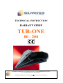
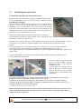
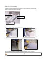
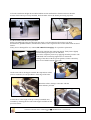
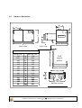
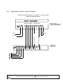
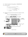
TECHNICAL INSTRUCTION
RADIANT STRIP
TUB-ONE
80 - 200
SOLARONICS Chauffage SA. 78, rue du Kemmel - B.P. 30173 – 59 428 ARMENTIERES Cedex France
Tel : + 33.3.20.10.59.59 - Fax : +33.3.20.35.57.22
TECHNICAL INSTRUCTION – RADIANT STRIP
-1-
TUB-ONE 80-200 - NT09002A-GB
SECTION 0 – GENERAL INFORMATION
Information for users
SECTION 1 – TECHNICAL DATA
1.1 Product identification data
1.2 TUB- ONE radiant strip introduction
1.3 Technical characteristics
1.4 Application
1.5 Description of the RCF series radiant strip
1.6 Principle of operation
1.7 Internal Wiring
1.8 Improper use
1.9 Standard accessories
SECTION 2 – PACKING, HANDLING AND TRANSPORTATION
2.1 Receipt of equipment
2.2 Handling and transportation
2.3 Lifting
2.4 Unpacking
2.5 Storage
SECTION 3 – INSTALLATION AND TESTING
3.1 General guidelines for installation
3.2 Installation
3.3 Positioning the burner
3.4 Assembly / Installation of the radiant sections
3.5 Connection to the electric and gas
3.6 Testing and commissioning
3.7 Adjustments
3.8 Gas conversion
SECTION 4 – PROTECTION SYSTEMS
4.1 Clothing
4.2 Residual risks
4.3 Emergency situations
4.4 Burner “lock out” indication
SECTION 5 – USER INSTRUCTIONS
5.1 Starting on the system
5.2 Switching off the system – short periods
5.3 Switching off the system - at the end of the season
5.4 Fault Finding
5.5 Warnings and security
SECTION 6 – MAINTENANCE
6.1 Maintenance requirements
6.2 Technical assistance request
SECTION 7 – DISMANTLING
SECTION 8 – APPENDICES
8.1 – Wall bracket template
8.2 – External burner dimensions
8.3 – Security distances
8.4 – Distances to crane
8.5 – Temperature control
8.6 – Electrical connection of a 2 stages burner
TECHNICAL INSTRUCTION – RADIANT STRIP
-2-
TUB-ONE 80-200 - NT09002A-GB
Page 3
Page 3
Page 4
Page 4
Page 4
Page 5
Page 6
Page 6
Page 7
Page 7
Page 7
Page 7
Page 9
Page 9
Page 9
Page 9
Page 9
Page 9
Page 10
Page 10
Page 10
Page 11
Page 12
Page 16
Page 19
Page 20
Page 20
Page 20
Page 20
Page 20
Page 20
Page 21
Page 21
Page 21
Page 22
Page 22
Page 22
Page 23
Page 23
Page 23
Page 24
Page 24
Page 25
Page 25
Page 26
Page 27
Page 27
Page 28
Page 29
SECTION 0 – GENERAL INFORMATION
Introduction
We thank you for choosing a SOLARONICS Chauffage product and inform you that:
• The aim of this guide is only informative and can be subject to variation without warning;
• This guide cannot be partially or entirely reproduced, diffused, copied or saved in a storage
system in any form or in any media, mechanical, magnetic, optical, chemical or others,
without written authorisation by SOLARONICS Chauffage.
• This guide must be kept until the final decommissioning of the product and, in case of
change of ownership of the heater, must be handed over to the new owner.
• In case of damage and consequent failure of the product, SOLARONICS Chauffage will not accept
liability for any consequential failure or loss due to failure of the product and will not extend
the warranty.
This installation and service manual should be considered part of the product and must be
kept for the entire life of the product.
These instructions should be carefully read before installation and or use of the product.
Information for users
This guide is an integral part of the product and must be easily accessible to both user and
authorised maintenance personnel.
The authorised maintenance personnel are obliged to understand the contents of this guide before
putting the product into use.
In case of loss or damage of this guide please contact the Technical Department of SOLARONICS
Chauffage for a copy. Please quote the identification data for the system as found on the product data
plate.
SOLARONICS Chauffage does not accept any liability for damage or loss caused by:
- incorrect or inappropriate use of this product,
- incorrect installation,
- inappropriate electrical or gas supply,
inappropriate or modified installation environment from the one given at order stage,
- poor maintenance, unauthorized modifications, use of incorrect and/or unathorized spare
parts, removal of active and passive protection of the appliance,
- lack of observance of the user instructions, carelessness, etc.
The product is manufactured in accordance with the following CE directives:
-
Machine directive 98/37/CE,
Low Voltage Directive 73/23/CE,
Electromagnetic Compatibility Directive 89/336/CE,
Gas Devices Directive 90/396/CE.
It is absolutely forbidden to modify the products and its application.
TECHNICAL INSTRUCTION – RADIANT STRIP
-3-
TUB-ONE 80-200 - NT09002A-GB
SECTION 1 – TECHNICAL DATA
1.1
Product identification data
The main identification data of the product (serial number, model, etc) is recorded on the data plate on the
product.
In case of technical assistance or spare parts request, please quote the product model and serial
number.
1.2
TUB- ONE radiant strip introduction
The RCF 80 - 200 series is an independent heating system that can be installed both on the ceiling
and on the wall. The range consists of heaters with burners giving outputs between 80 and 200 kW and a
maximum length of 120 metres. They take advantage of the electromagnetic heat wave transmission
principle in the infrared spectrum, heating solid elements and avoiding heat absorption by the layer
of air between the floor and the heater during start up.
The thermal energy flux directly heats people, floors and structures that return heat by convection to
the air around them, guaranteeing a comfortable microclimate.
Even though the Tub-one uses the same principle as modulated radiant tube heaters, it differs from
them by the lower surface temperature of the radiant strips and by the different horizontal
geometrical formations possible. Moreover the advanced combustion and flue recycling system
employed by Tub-one means that it produces very low atmospheric emissions of CO and NOx, and
makes the system very fuel-efficient.
TECHNICAL INSTRUCTION – RADIANT STRIP
-4-
TUB-ONE 80-200 - NT09002A-GB
1.3
Technical characteristics
Burner type
RCF 80
RCF 100
RCF 150
RCF 200
Nominal thermic capacity ( P.C.I.)
kW
80
100
150
200
Heat Output
kW
72
90
135
180
Type of flues discharged
Category
NOx class
Consumption
B22
G20 (gaz naturel)
I2H
G31 (Propane)
I3P+
G20 (gaz naturel)
3
3
3
4
G31 (Propane)
3
3
2
3
Natural gas H - G20
(Hi) 9,45 kW/m3
m3/h
8.5
10.4
15,6
20,8
Propane - G31
(Hi) 12,88 kW/kg
kg/h
6,0
7,6
11,0
15,0
“
∅ Gas connection
Natural gas - G20
∅ Nozzles
Propane - G31
Gas burner
Natural gas - G20
Pressure
Propane - G31
Natural gas - G20
Partition
Propane - G31
∅ Flues duct
Net pressure flues discharge
Mass flues flow – Natural gas
Mass flues flow - Propane
Supply voltage
Maximum current
Maximum electrical power absorbed total
Protection grade
Weight – Burner
Weight – 4 meters radiant section
Weight – 2 meters radiant section
Total section length ( Min. – Max.)
1“
9,00 (3
5,30
5,5
22,0
-
mm
Mbar
mm
mm
Pa
g/s
g/s
A
W
IP
kg
kg
kg
m
1“
9,00 (3
5,30
9,5
30,0
-
100
60
40
120
120
126
160
400V. - 50 Hz (3N ∼)
3
1 200
43
85
80
40
50-70
50-70
1/2
1“
12,00 (2
9,00 (3
7,0
6,0
10.5
9.6
1“ 1/2
12,00 (2
9,00 (3
14,0
12,0
10.5
9.6
150
60
40
234
242
273
248
400V. - 50 Hz (3N ∼)
10
4 500
43
170
80
40
70-100
80-120
Table 1 – Technical characteristics
Nominal pressure Gas Supply
Do not use this product if gas pressure is
not between:
Do not use this product if gas pressure is
not between:
If the pressure is higher than:
It is necessary to install pressure
regulators to bring the pressure in line with
the required values.
2nd family gas, G20 – Natural gas
3rd family gas, G31 – Propane
G20 – Natural gas
G31 – Propane
G20 – Natural gas
G31 – Propane
G20 – Natural gas
G31 – Propane
20 mbar
37 mbar
17 ÷ 25 mbar
25 ÷ 45 mbar
17 mbar
25 mbar
25mbar
45 mbar
Table 2 – Gas network supply pressures
NOTES: 1) – the data refers to the maximum lentght of the radiant strips
2) – without nozzle (direct)
3) – Threaded hole G 1/ 8 “
TECHNICAL INSTRUCTION – RADIANT STRIP
-5-
TUB-ONE 80-200 - NT09002A-GB
1.4
Application
TUB One radiant strip is an independent suspended gas fired radiant heater, designed to heat industrial
and
commercial premises, sports centres and any large volume non-domestic environments subject to
current legislation.
The heat output, quantity of units, height of installation (minimum 4 metres from the floor) and the
position of the heaters have all to be established through heat loss calculations derived from the
system project, and observing current legislation.
This product must not be used for any appliacation other than the ones it has been designed for.
For the system design it is recommended that you contact competent and qualified (Planning offices
and/or qualified).
1.5
Description of TUB-ONE Radiant strip
TUB One radiant strip is an independent suspended radiant
gas heater, using methane or propane gas. It is composed
of a burner, and a radiant heat distribution system,
consisting of special radiant sections.
The burner, main structure made of steel and side panels of
stainless steel, contains the combustion group, the
ventilation group and the electric switchboard with control
and security organs; it is supplied complete of hanging
brackets made of stainless steel necessary for its internal or
external installation.
The radiant section is composed of a series of modules of
variable lengths (2÷4 metre each) that connect together throught appropriate brackets inserted in the
modules.
Every module is made with special tubes, realised in aluminised steel, on which is positioned a special
aluminium insulation panel with high reflective power; the main structure is made of painted laminated
steel, it sustains and contains all the components.
The steel tubes are connected with special nipples (patented system). These are provided with special
high temperature resistant elastic that is kept into position through collars hooked to the main structure of
the section. This solution permits to compensate the expansion due to the module heating, so that they do
not cause dangerous expansion and tensions without using sealing compounds or putties and obtaining a
long duration guarantee.
TECHNICAL INSTRUCTION – RADIANT STRIP
-6-
TUB-ONE 80-200 - NT09002A-GB
1.6
Working principle
Heat production occurs through a special air vein burner, assisted by security and command systems, it
has been preset and tested in the factory. The ventilator was studied and built purposely to put the entire
radiant tube system in depression against the environment, to draw the necessary air for combustion, to
recycle the combustion products (to even the temperature inside the tubes) and to expel the combustion
flues through a flues discharge duct.
The combustion system is constantly controlled by an electronic device that at every request of heat starts
the electro ventilator, to verify the depression inside the radiant circuit, to light the burner, to verify the
correct presence of the flame and in case of anomalies to stop immediately the burner’s gas flow putting it
into a security block.
The radiant section, kept at an average temperature of 250°C, transmits to the surrounding environment
the requested heat, helped by a glass wool panel covered on both side by aluminium with high reflection
capacity that is positioned on top of the radiant tubes, the latter are treated with special black paint with
high radiant emission coefficient.
Temperature regulation will be handled by an electronic data acquisition device, through a black bulb
sensor positioned in the heated environment, controlling the temperature by managing the burner’s phases
depending on the set parameters and the working hours.
1.7
Electrical network
Electrical network shall complain with regulation and norms.
It is absolutely forbidden to modify the switch-board.
It is absolutely forbidden to estinguish fires with water.
During the use of the system, do not touch the tubes – Burns danger.
During the use of the product, do not touch the ventilator – Mechanical danger.
1.8
Improper use
The unit can’t be used for different scopes than the one stated in the paragraph 1.3 of this guide.
It is absolutely forbidden to install the product in environments with danger of explosion and highly
inflammable materials.
1.9
Standard accessories
The unit is provided with the following equipments:
1) Combustion group
Complete of special air vein combustion head, stainless steel combustion chamber,
double shutter multifunctional gas group, air pressure switch, fume recycle ventilator, fume
discharge valve, security and control electronic module, wired internal electric network,
containment box and stainless steel protection with sealed inspection opening.
TECHNICAL INSTRUCTION – RADIANT STRIP
-7-
TUB-ONE 80-200 - NT09002A-GB
2) Straight radiant sections
Lengths of 2 or 4 meters, each one is composed by 2 exchange tubes made of aluminium steel that have Φ
250 mm, aluminium reflecting panel to optimise the heat reflection, top glass wool insulation, suspension
and containing external structure, special tube connection devices. *
3) 90° radiant sections
Each one with 2 exchange tubes made of aluminised steel that have Φ 250, aluminium reflecting panel to
optimise the heat reflection, top insulation made of mineral wool, suspension and Containing external
structure, special tube connection devices. *
* The number of straight and curved radiant sections is established taking into consideration
the development of the system and the power of the burner in relation to the dimensions of the
premises to be heated.
4) Fume discharge terminal made of stainless steel
5) Fume duct L.250 mm. with fume drawing, made of stainless steel
6) Burner’s support bracket made of stainless steel
7) External grey putty cartridge for sealing
8) High temperature resistant black painting for touching up
Optional accessories:
- Fume duct
- Temperature control and electronic switchboard
- 45° curved radiant sections
- Special radiant sections
- Aluminium reflector for straight and curved sections
TECHNICAL INSTRUCTION – RADIANT STRIP
-8-
TUB-ONE 80-200 - NT09002A-GB
SECTION 2 – PACKING, LOGISTIC AND TRANSPORT
2.1 Equipment receiving
When the package is delivered to the client, the latter is obliged to control the integrity of the
product.
Control the package an its contents, in case of damage due to the
transport, the client has to tick damage claim box on the transport
document, this has to be countersigned by the carrier and a copy has
to be sent to SOLARONICS Chauffage.
2.2
Logistic and transport
Pay high attention handling the TUB-ONE units during the phases of downloading from the carrier,
logistics and positioning, to avoid damages to carpentry and to the most delicate components (tubes, fans,
etc.).
2.3
Lifting
Ensure that the maximum lifting power of the lifter is adequate to the products weight.
The product has to be lifted only by qualified personnel. Pay maximum care in handling the radiant strips
while downloading form the carrier, positioning and the assembling the sections, to avoid damages.
If lifting people the machinery has to be specifically certified and used by qualified personnel.
It is absolutely forbidden to stay under the hanging loads and inside the action area of the lifter.
2.4
Unpacking
Carry the radiant tubes units in the installation area.
Free all the wrapped components from the packaging and collect everything to prevent the potential
danger of fire and suffocation of people or animals.
Packaging material discharge has to be done in specification to the norms applicable in the destination
Country of the TUB One.
2.5
Storage
The temperature during transport and storage has to be between -10 and 50 °C.
Whenever the TUB-ONE units are stored, it has to be ensured that the relative humidity in the storage is
between 5% and 95%..
TECHNICAL INSTRUCTION – RADIANT STRIP
-9-
TUB-ONE 80-200 - NT09002A-GB
SECTION 3 – INSTALLATION and TESTS
3.1
General warning for installation
The installation of the TUB-ONE should be performed by qualified personnel following the instructions
in this manual and the usual rules and standards
.
Matériaux
combustibles
Matériaux
combustibles
0,5m
1m
Matériaux
combustibles
Hauteur suivant
tableau ci-dessus
1,25 m
m
0,6
Matériaux
combustibles
The
distance
between
the
ground
and
the
radiant
must
be
at
least
4
meters.
Before starting the installation of radiant systems TUB-ONE it is necessary to ensure that all components
have been unpacked and are in good condition.
3.2
Installation
The materials and personal lifting machinery must be available on the settlement and have a lifting
capacity sufficient.
The staff for the facility will be trained, must wear and use protective equipment in accordance with
existing regulations, safety shoes, gloves, helmet, harness, goggles etc ...
Before positioning the elements, check that they are not in contradiction with the use of wrecking
cranes, cranes ...
TECHNICAL INSTRUCTION – RADIANT STRIP
- 10 -
TUB-ONE 80-200 - NT09002A-GB
3.3
Positioning the burner Box
To install the unit follow the instructions below:
The burner has to be installed by using the provided suspension bracket,
in case of impossibility to use it or if it is necessary to modify it, consult
SOLARONICS Chauffage.
Do not position the unit directly on the floor, roofs, etc. keep the burner
lifted of at least 50 cm., height depends by the weather of the
installation area (it is necessary to take into consideration eventual
snow falls). On the bottom part of the unit there are the openings for the
combustion air to enter: do not block or reduce these openings, they are
essential for a correct functioning of the unit.
Identify the height and position of the radiant strip by comparing it
with the internal plan of the premises; sign the correct positioning of the
combustion group on the external wall.
Reproduce the measures indicated in the attachment section on the wall: drilling template: sign the
referral holes for the fischers (or tiranti through the wall) and the opening for the tubes to pass
through.
Carry out the holes to put in the fischers taking care to chose the correct ones relating to the wall
composition, taking into consideration the weight of the combustion group (see page 5).
(It is suggested the use, for example, threaded bars Ø 12mm. through the wall and counter plates on the
internal wall)
Firmly fix the bracket to the wall and seal with putty in the external contact area with the wall to
avoid possible water infiltrations.
Lean the burner on the bracket and
push it to the shoulder, inserting
through the hole in the wall the
combustion group.
Fix the burner to the bracket with the
plates at the side of it and seal with
putty on the external area of contact
with the wall to avoid possible water
infiltrations.
Set up the fume discharge duct, fixing it firmly to the wall and positioning at its extremity the
discharge terminal; ensure that the tubes are perfectly sealed.
Predispose the anchor points internally to the building, to the ceiling or to other building’s
structures, hang precise length chains to sustain the radiant sections. (An anchor point every 4
meters* starting from the combustion group).
* (2 meters in case the radiant section is 2 meter long)
The anchor points have to be chosen in a way that the sustaining chains do not cause excessive strain
to the connecting brackets and to the supports of the sections: avoid to create higher angles than 15°
compared with the vertical line.
TECHNICAL INSTRUCTION – RADIANT STRIP
- 11 -
TUB-ONE 80-200 - NT09002A-GB
3.4
Assembly / Installation of the radiant sections
General pattern assembly
Female bracket
Female bracket
Side panel
Intermediate
Male bracket
Male bracket
Fixation hole
Insulation panel
TECHNICAL INSTRUCTION – RADIANT STRIP
- 12 -
TUB-ONE 80-200 - NT09002A-GB
Details of the process of assembling
Assemble on the floor the radiant section structure by using a male bracket, an intermediate
bracket, a female bracket and two side panels.
Side hoops
Male Bracket
Female Bracket
Intermediate
Bracket
Realise the matches (bracket – side panel) through the self perforing screws provided.
Complete the assembly by inserting the insulation sandwich panels in the sides. Insert at 2 meters
(referral: side insulation panel dimension) the intermediate bracket fixing it with the self perforing screws
Peel the eventual protective layer from the assembled components (example: side panels)
TECHNICAL INSTRUCTION – RADIANT STRIP
- 13 -
TUB-ONE 80-200 - NT09002A-GB
Lift to the installation height the assembled radiant section and hook the female bracket to the male
bracket of the burner previously installed, hook the other side to the chains previously prepared.
Fix the brackets with the screws provided.
Before assembling the tubes and inserting the nipple verify that the tubes do not have any deep
deformations, squashed borders, metallic burrs; in these cases regenerate the circular status with an suited
utensil .
If they are too damaged for use, contact SOLARONICS Chauffage for a possible replacement.
Proceed by inserting the connecting nipple: firstly insert slightly
inclined the nipple respect to the tube and
proceed to completely insert it by applying alternate pressure with
both hands. The connecting nipples have to ensure the
sealing of the tubes with the special gaskets, for this reason they
have to be of hard insertion in the tube .
On the same side as the nipple assemble the suspensions collars
(one for each tube) in correspondence of the edge of the tube.
Block the collars (clamps) to the tube with the
bolts and nuts provided.
Lift the tubes at the height of the previously assembled ones;
assemble by inserting the free side in the nipple available on the
previous section..
TECHNICAL INSTRUCTION – RADIANT STRIP
- 14 -
TUB-ONE 80-200 - NT09002A-GB
Fix the tubes on the opposite side (to the male bracket of the radiant section) with the connecting bolts of
the collars previously assembled on them.
The emitter tubes are shorter than the sections
(1.5 ÷ 2.5 cm) so it is not necessary to push them
to the shoulder of the previous nipple.
Complete the section by overlapping the superior
insulation panel.
Control that the sections are perfectly horizontal and eventually correct their set up with connecting rods
to the suspension chains.
Repeat the procedure for the successive radiant sections.
When the assembly is finished control that the single section is horizontal, that the suspension
chains are perfectly anchored (both to the section and to the building’s structure) and that the tubes
anchoring bolts and collars are sufficiently tightened.
TECHNICAL INSTRUCTION – RADIANT STRIP
- 15 -
TUB-ONE 80-200 - NT09002A-GB
3.5
Connection to the electric and gas network
The first start and testing of the electric and gas network connections have to be done by qualified
personnel.
All the components used for the electric/gas network have to be certified and homologated.
3.5.1
Gas network connection
The gas supplied to the burner has to be the one indicated on
the gas indicator plate, and has to be connected through the
predisposed attachment on the burner. (Before attaching take
off the closing tap!)
The gas supply pressure has to respect the values indicated in
the table in this guide. (Page 5)
If the gas pressure is over the limit of the one indicated in the
table, install pressure reducers.
The gas supply system has to be proportional to the gas’ nature related to the maximum input power of
the burner/s and has to have all the control and security devices prescribed by in force norms relatively to
the available user devices, to do this it is necessary to consult with qualified personnel in this field.
Any unit has to have the gas-intercepting cock that has to be easily reachable in case of
maintenance operations.
To avoid eventual vibration transmittance from the burner to the gas pipes, it is suggested to use a
special stainless steel flexible junction.
All the connections have to be sealed with gaskets or other sealing materials suited to the gas used.
Before injecting the fuel in the ducts, accurately clean the ducts from any residual material, it is
suggested to install an adequate filter.
Once finished the installation of the system test the sealing and eventually eliminate the leaks.
It is absolutely forbidden to use fire to look for eventual gas leaks during the seal test.
Do not smoke, use lighters or other fire sources – Fire and explosion danger.
Before lighting the burner, run off the air that is in the tubes.
TUB One burner units are equipped with gas electro valves suited to work with different network’s
pressure,
depending on the type of gas used and of the destination country as indicated on the burner’s plate
and on this guide.
The range of allowed input pressures is stated in “1.3 Technical Data” page
TECHNICAL INSTRUCTION – RADIANT STRIP
- 16 -
TUB-ONE 80-200 - NT09002A-GB
5.
3.5.2
Electrical network connection
In case of power burners at two levels of power, stick with the following instructions but respect the
electrical connections shown in the chart on page 29, section 8.6.
The foreseen supply voltage is:
- 400 V 3N ~ 50 Hz
Verify that the burner’s electric supply corresponds to the one stated on the burner’s plate and on
this guide..
The electric connections have to be done by qualified personnel.
Before operating on the electric supply cable, be sure that the network has been severed.
Foresee an efficient earthing using the terminals.
Total electric security of the unit is reached only when the latter is correctly connected to an
efficient earthing system, carried out as requested by the norms in force.
It is necessary to verify this requirement. Do not use gas tubes as earthing of electric devices.
The electric system has to be adequate to the maximum power absorbed by the unit, this is stated on
the data plate and in this guide, make sure that the cable diameter is suited to the power absorption
of the unit.
Insert between the radiant strip and electric network a main switch having a minimum distance
between the contacts of 3 mm for each pole in accordance to the CEI-EN norms, predisposing it in
an easily reachable position by the user
Verify the electrical scheme inside the burner and/or in this guide and execute the connection
indicated above.
For the unit to work properly it is necessary to respect the phases and neutral as indicated in the
scheme.
Security signal
Operation signal
Reset
Burner in operation
Terminals 1-2 : operation dry contact
Les bornes 3-4 : reset dry contact
Les bornes 5 et 7 : to be connected to any signals (max 0.5 A)
Near the main switch install the following devices:
· An environment temperature controller (black bulb sensor);
· A burner unblocking button (normally open type); *
· An eventual illumination sign for when the burner is blocked *
· An eventual illumination sign for the start up of the system *.
* if not available on the temperature controller
TECHNICAL INSTRUCTION – RADIANT STRIP
- 17 -
TUB-ONE 80-200 - NT09002A-GB
TA
VG
PA
PM
CF
TR1
RAF
LR
LV
TRA
EA
ER
Room thermostat
Gas valve
Air Pressure switch
Flame control
Contrôle de flamme
EMC Filter
Relay timer
Contactor motor fan
Witness up security
Tell-tale
Ignition transformer
Ignition electrode
Ionization electrode
3.5.3
Système de sortie de fumée
Every unit has to discharge combustion products directly into the external environment trough an
evacuation duct made of metallic material
The evacuation duct has to have the same diameter as the one on the burner box (it is eventually accepted
a larger diameter)..
The evacuation ducts can be maximum 4 metres long, including two
90° bends. The distance between the connection of the burner and the
first elbow should be at least 4 times the diameter of the chimney flue.
For example for a diameter of 150 mm minimum distance between the
connection of the burner and the first bend is 600 mm.
The installation of the duct has to be done so that its weight does not
strain the burner.
In case the duct goes through a wall, the latter has to be protected from
the heat.
Use only flues with a smooth surface.
When the burner is installed externally, the ducts longer than 2 meters
have to be insulated.
TECHNICAL INSTRUCTION – RADIANT STRIP
- 18 -
TUB-ONE 80-200 - NT09002A-GB
3.6
Testing and starting of the burner
These operations have to be done by qualified personnel
Ensure that operations below have been made.
The protective layer has been peeled from each external surface;
All the legislations in force have been respected;
All the connection have been done in specification to the instructions reported in this guide;
The gas connections and discharge duct are well sealed.
The suspension devices are effective
Before starting the unit control that:
The gas nature correspond to the one indicated on the burner’s plate;
The electric supply is the one indicated on the burner’s plate;
The gas ducts have been blooded from eventual residual materials and air presence;
The intercepting gas cock is open
Bring the electric supply to the unit with the general switch and adjust the temperature controller
(positioning the environment thermostat to the maximum temperature).
With the fan in function (the pre ventilation phase lasts 30÷40 seconds) verify the correct direction of the
rotation, if it is not rotating in the correct direction switch off the unit and do the apply changes to the
electric system.
Verify that the product does not produce strange noises due to friction or movement of objects in the
tubes, in these cases switch immediately off the unit and identify the cause.
With the burner on, verify the nominal power: control the consumption in a unit of time and transform it
in the equivalent for an hour; compare it with the data reported in the technical characteristics table.
Air the premises: during the first use, it is possible that flues create inside the premises due to the
manufacturing residuals (these flues will not create in the next uses).
Verify the functioning of the environment thermostat.
Keep in mind that the fan continues to work for a few minutes after the burner is switched off for the
cleaning operation, after this the burner can be restarted.
Verify the functioning of the “Block”:
When the burner is working, close the gas cock, the burner has to put itself into a block state, the fan has
to continue working to fulfil the cleaning operation, after this the burner can be restarted by pushing the
unblock/reset button.
Let the system work for at least one hour, so that the flues due to the manufacturing lubricant finishing,
before doing eventual combustion controls.
In any case, do not let the system work if there are anomalies and contact immediately the After
Sales Service of SOLARONICS Chauffage.
TECHNICAL INSTRUCTION – RADIANT STRIP
- 19 -
TUB-ONE 80-200 - NT09002A-GB
3.7
Change in settings
The manufacturer has made the setting of the burner after manufacture. To make these settings, it is
necessary to contact the qualified people.
3.8
Gas switching
The transformation of one family gas to another family gas can be easily done even with the burner
already installed.
This operation has to be done by authorised personnel.
The burner is provided to function with Natural or Propane gas as requested in the order; the type of gas
expected is stated on the products plate..
For the operations of gas switching to refer to the instructions included with the kit change of gas
delivered by SOLARONICS Chauffage.
SECTION 4 – PROTECTION SYSTEMS
4.1
Clothing
As the unit has to be installed at least 4 metres of height, so it is not reachable by users during the normal
functioning, there is no particular clothing restrictions.
The maintenance personnel have to wear correct clothing and individual personal protections.
4.2
Risques résiduels
During function, the radiant tubes reach temperatures higher than 50 °C.
While the system is in function do not touch the tubes – Burning danger.
In case of need of maintenance and/or operations near the radiant tubes, switch off the system allowing some
time to pass to make sure that the heat of the tubes cannot cause damage to the personnel.
When moving objects pay attention to not hit the radiant tubes when lifting them, this could cause the objects
to fall and damage to the suspension devices.
Pay attention to the fan movement. Do not introduce limbs. – Mechanical danger
4.3
Emergency situations
In case of emergency:
Stop immediately the system, sever the gas line and open the electric circuit with the main switch
Identify and eliminate the problem, check the original cause
Contact the Technical Assistance Service of Solaronics Chauffage.
It is absolutely forbidden to use water to estinguish fires.
TECHNICAL INSTRUCTION – RADIANT STRIP
- 20 -
TUB-ONE 80-200 - NT09002A-GB
4.4
Indications de mise en sécurité du brûleur
La mise en sécurité du brûleur est indiquée par la lampe
rouge dans le caisson brûleur ou à proximité du
thermostat d’ambiance (si l’indicateur de défaut a été
reporté).
Pour remettre en fonctionnement le brûleur en sécurité,
appuyer sur le bouton reset.
SECTION 5 – USE OF THE PRODUCT (FOR THE USER)
5.1
Starting of the system
Give voltage to the unit with the general switch.
Set the temperature desired with the predisposed control device (environment thermostat); if the set
temperature is higher than the environment’s temperature the fan will switch on and when finished the
cleaning operation (around 30 ÷ 40 sec.) the burner’s flame will lit.
In case the system does not switch on, this is indicated by the predisposed light on the switchboard
(blocked unit), restart the burner by pressing the reset switch on the switchboard. (See point 5.4)
The burner will be managed automatically by the temperature control device or by eventual programmed
times to maintain the desired temperature in the premises
TECHNICAL INSTRUCTION – RADIANT STRIP
- 21 -
TUB-ONE 80-200 - NT09002A-GB
5.2
Switching of the system
To switch off the system for a short period it is sufficient to lower the temperature of the environment
thermostat to the minimum.
When the temperature set on the thermostat is lower than the one in the premises the burner will switch
off, the fan will continue to work for a few minutes (4÷7) to do the cleaning operation of the flues circuit
and radiant tubes: during this phase do not cut off the voltage with the general switch.
Do not use the general switch but lower the thermostat temperature to switch off the system
5.3
Switching off at the end of the heating season
At the end of the use period, the system can be stopped for the end of the season following these
instructions:
Lower the temperature of the environment thermostat to the minimum;
Close the gas interception cock;
Cut off the voltage with the general switch after 10 minutes to permit the cleaning operation of radiant
tubes and flues system to be complete.
5.4
Abnormal operation
In case of functioning anomalies proceed as follows:
Verify the presence of gas in the network (example: gas interception valve is closed) ⇒ open the gas
interception valve
Verify the presence of voltage (example: general switch is open) ⇒ close the general switch
Verify the temperature set on the environment thermostat ⇒ higher the value set
Verify the eventual programmed clock (example: inserted programme off) ⇒ modify the clock
program
Verify that the burner is not in block condition (environment thermostat’s red light is on) ⇒ press the
reset/unblock switch. (RST)
In case of repeated blocks of the burner do not insist over 2 ÷ 3 manual unblocking procedures but contact
qualified personnel.
In case none of the above conditions took place:
Switch off the system;
Close the gas interception valve;
Sever the electric supply;
Contact the Technical Assistance Service of SOLARONICS Chauffage, the system’s installer or a
qualified technician.
.
TECHNICAL INSTRUCTION – RADIANT STRIP
- 22 -
TUB-ONE 80-200 - NT09002A-GB
5.5
Warnings and security
If the system works with Propane gas (L.P.G.), during the operations of tank refuelling the burner has
to be previously switched off; switch it back on after having finished the refuelling operation.
In case of intervention or maintenance on structures near the burner or flues discharge duct, switch off
the unit. When finished the intervention have the efficiency checked by qualified personnel.
In case of intervention or maintenance on structures near the radiant sections, switch off the burner at
least half an hour before the intervention, if the temperature of the radiant tube surface is higher than
50°C there is burns danger; switch on the unit only when the interventions are completed.
If the characteristic gas smell is sensed, do not action electric switches, telephone and other products
that can cause sparkles, do not smoke, do not light fires, do not use free flame equipment etc.
Open doors and windows to air the premises, close manually the external gas interception valve and
contact qualified personnel to intervene.
SECTION 6 – MAINTENANCE
6.1
Maintenance security norms
Maintenance personnel have to be qualified.
Before applying any maintenance operation, carefully read this section of the guide. For any necessity contact the
Technical Assistance of Solaronics Chauffage.
Solaronics Chauffage declines any responsibility for any damage or dysfunction if due to lack of application of
the indications in this section of the guide
Maintenance personnel doesn’t have to wear clothes with large sleeves, laces or belts that could cause
danger; furthermore, they have to use the personal protection devices in specification to the legislations in
force.
Before undertaking any cleaning and maintenance operation previously switch off the unit and wait
that the surface of the radiant tubes and flues discharge duct cool down (wait at least an hour), cut off
the electric voltage with the general switch.
Do not clean the unit or any parts of it with easily inflammable substances (example fuel, alcohol, etc.)
Do not clean the panels, painted parts and plastic parts with paint diluents.
Before the beginning of the heating season it is necessary to verify that the product works properly, so
that in case of malfunctioning there is time to do eventual maintenance/repairs.
TECHNICAL INSTRUCTION – RADIANT STRIP
- 23 -
TUB-ONE 80-200 - NT09002A-GB
Once a year check:
The general condition and functioning of the burner;
The general condition of the radiant sections;
The gas supply pressure;
The environment thermostat’s functioning;
The cleanliness and condition of the flues evacuation duct;
The condition of the suspension devices;
The security devices’ functioning.
During maintenance, expose the “work in progress” signs in a way that they are visible by all access
areas.
Record on a register all the maintenance carried out, making sure to sign: date, hour, type of maintenance
and name of the personnel that carried out the maintenance.
The eventual use of cleaning solvents has to be done without touching the electric cables.
It is forbidden to:
Deposit combustion materials near he switchboards.
Operate on the electric parts without having previously selected the electrical supply line.
Operate on any part of the unit without having switched off the system
Operate with the security systems deactivated or disconnected.
Desactivate or trick the alarm signals applied on the product.
Once finished the maintenance, before restoring the electric supply and switch on the system, accurately
control that no equipment and/or various materials have been forgotten near or inside the unit and
especially near moving organs.
6.2
Technical assistance request
For any technical assistance request, contact immediately the Hot Line of SOLARONICS Chauffage.
+33 (0) 891 701 802
Solaronics Chauffage
Département Services
BP30173
ZI n°3
78 rue du Kemmel
59428 Armenitères
SECTION 7 – DISMANTLING
The dismantling of the system has to be done by specialised personnel with correct instruments and
personal protection devices.
Do not smoke and not use free flames
In case of dismantling or alienation of the system, it is necessary to recover all the materials and send
them to the respective collection centres, possibly referring to specialised companies.
TECHNICAL INSTRUCTION – RADIANT STRIP
- 24 -
TUB-ONE 80-200 - NT09002A-GB
SECTION 8 – SUPPLEMENTARY DATA
8.1
Wall bracket’s template
For burners of 80 kW to 100 kW
FORATURA PARETE PER STAFFA
4 percements avec tiges et contre-plaques
4 holes for rods and against plate
Ouverture nécessaire
au passage
APERTURA
PARETE
Necessary
opening
for the
des tubes
PASSAGGIO
TUBAZIONI
passage of tubes
For burners of 150 kW to 200 kW
FO RATUR A NELLA PARETE PER STAFFA
FORATURA PARETE PER STAFFA
444percements
avec
tiges
holes foravec
rods
and
against plate
percements
tiges
etet
contre-plaques
contre-plaques
A POuverture
E R T U Rnécessaire
A N E L L AauPpassage
ARETE
desPARETE
Ouverture
nécessaire
passage
P
A
S
S
A
G
G
IO
Ttubes
Uau
Bfor
A Zthe
IO N I
APERTURA
Necessary
opening
des tubes
PASSAGGIO
passage
of tubesTUBAZIONI
TECHNICAL INSTRUCTION – RADIANT STRIP
- 25 -
TUB-ONE 80-200 - NT09002A-GB
8.2
Burners dimensions
Impresind
Impresind
CLIMATIZZAZIONE PRODUTTIVA
CLIMATIZZAZIONE PRODUTTIVA
TUB-ONE
VUE ARRIERE
Back view
SideLATERALE
view
VUE
Dimensions en mm (+/- 5)
RCF 80 ÷100
530
1000
320
105
260
145
370
600
900
665
590
330
135
90
RCF 150 ÷ 200
A
B
C
D
E
F
G
H
L
M
N
O
P
kg
750
1220
320
175
325
185
455
760
1140
820
810
600
90
170
Bride
de
Wall
support de
support
brûleur
bracket
Radiant
section
Section radiante
TECHNICAL INSTRUCTION – RADIANT STRIP
- 26 -
TUB-ONE 80-200 - NT09002A-GB
8.3
Security distances
Matériaux
Combustible
combustibles
materials
Combustible
Matériaux
combustibles
materials
0,5m
1m
Combustible
Matériaux
combustibles
materials
Hauteur suivant
tableau ci-dessus
1,25 m
m
0,6
Matériaux
Combustible
combustibles
materials
8.4
Distance from cranes
SECTION
RADIANTE
: DISTANCE PAR
A UN PONT
ROULANT
SEZIONI
RADIANTI
POSIZIONATE
IN RAPPORT
PROSSIMITA'
CARRO
PONTE
RADIANT
SECTION
: DISTANCE
FROM
A DI
CRANE
Insulation
sandwich
Panneau isolant
panel
Minde roche
av ec –laine
Ep. Mini
thickness
of 55 cm
cm
Min. 5 cm
m oteur
Engine
CRANE
Pont-roulant
TECHNICAL INSTRUCTION – RADIANT STRIP
- 27 -
TUB-ONE 80-200 - NT09002A-GB
Temperature control – electrical scheme
Electrical connection scheme for a TUB One – 1 stage controller
Schéma de connexion correspondant au coffret de contrôle pour un systéme Tub one 1 allure
Buner
of 80/100/150/200
pour RCF
80/100/150/200 kW
SCP 933/A(B)
Temperature
control
switchboard
– Sensor
reset – 2 set
Coffret
de contrôle
pour un
systéme tubfor
oneTUB
avecOne
sonde
à boule –noire,
bouton réarmement,temperature
2 niveaux de température,
( horloge
programmable option).
points – clock
in option
1 2 3 4 5 6 7 PC
Phase
Phase
Neutre
Neutral
230 V (ph + N) 50hz
Sonde
Probe
RS T N 1 2 3 4 5 6 7
Thermostat
Thermostat
Rearmement
Reset
Signal
Signal
phase 1
phase 2
phase 3
Neutre
400 V (tri + N) 50hz
TECHNICAL INSTRUCTION – RADIANT STRIP
- 28 -
Liaison électrique
Electrical
connections to be
à effectuer par l'installateur
made by the installer
Security
signal de signal
sécurité
LN
Operating
signal
signal de Fonctionnement
8.5
TUB-ONE 80-200 - NT09002A-GB
Bornier
brûleur
Burner
RCF 80-100
Terminal
box
RCF 150-200
8.6
Electrical connection of a 2 stages burner – 80/100/150/200 kW
8.6.1
Electrical connection
Burner
Security signal
Reset
Thermostat – 2nd stage
Thermostat – 1st stage
8.6.2
Temperature control: electrical connection scheme between temperature controller
and burner
Electrical connection scheme for a TUB One – 2 stages controller
Schéma de connexion correspondant au coffret de contrôle pour un systéme Tub one 2 allures
Buner of 80/100/150/200 kW
pour RCF 80/100/150/200
SCP 933/C(D)
Coffret
de contrôle
pour un
systéme tubfor
oneTUB
avec One
sonde
boule noire,
Temperature
control
switchboard
– àSensor
– reset – 2 set
bouton réarmement,temperature
2 niveaux de température,
( horloge
programmable option).
points – clock
in option
L N
1 2 3 4 5 6 7 PC
Phase
Phase
Electrical
Liaison
électrique
to be
àconnexions
effectuer
par l'installateur
made
by the installer
Sonde
Probe
Neutre
Neutral
230 V (Ph + N) 50hz
RSTN 1 2 3 4 5 6 7
Thermostat
Thermostat Thermostat
2° niveau
1° niveau
de
puissance
1st
stage
2nd
stage
Reset
Bouton
réarmement
de puissance
Security
Signal
designal
sécurité
Burner
Bornier Terminal
brûleur
box
RCF 80-100
RCF 150-200
Phase 1
Phase
1
Phase 2
2
Phase
Phase
Phase 33
Neutre
Neutral
TRI 400 V (Ph + N) 50hz
10 A
DO RESPECT
PHASES
RESPECTER
LES
PHASES
TECHNICAL INSTRUCTION – RADIANT STRIP
- 29 -
TUB-ONE 80-200 - NT09002A-GB


![[a] et la broche [b].](http://vs1.manualzilla.com/store/data/006331853_1-44cfdda9677a09ad42f916c0c51195b9-150x150.png)