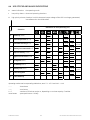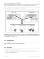
1
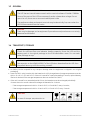
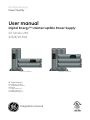
GE Digital Energy
Power Quality
User manual
Digital Energy™ Uninterruptible Power Supply
GT Series UPS
5/6/8/10 kVA
GT5000 RT / GT6000 RT
GE Digital Energy™
General Electric Company
CH – 6595 Riazzino (Locarno)
Switzerland
T +41 (0)91 / 850 51 51
F +41 (0)91 / 850 52 52
www.GEDigitalEnergy.com
imagination at work
GT8000 RT / GT10000 RT
User manual
GT Series - Uninterruptible Power Supply
5/6/8/10 kVA
We thank you for selecting a General Electric Digital Energy™ GT Series
Uninterruptible Power Supply.
Please read these instructions carefully before installation and start-up of the
GT Series UPS. Keep this manual in a safe place for future reference.
Model:
GT Series / Series 1
Date of issue:
09.01.2008
File name:
OPM_GTS_XUL_5K0_10K_XUS_V010
Revision:
1.0
Identification No.:
Up-dating
Revision
Concern
Date
© General Electric Digital Energy™. All rights reserved; reproduction without permission prohibited. The content of this manual
may be subject to change without prior notice; no liability can be accepted for any error or omission. The illustrations and plans
describing the equipment are intended as general reference only and are not necessarily complete in every detail.
modifications reserved
2
User manual GT Series 5/6/8/10 kVA UPS 1.0 (US)
Contents
1
IMPORTANT SAFETY INSTRUCTIONS ....................................................................................................... 4
1.1
1.2
1.3
1.4
1.5
1.6
2
INTRODUCTION........................................................................................................................................... 7
2.1
2.2
2.3
2.4
3
Save these instructions.....................................................................................................................................................................4
Safety warnings and symbols .......................................................................................................................................................4
General......................................................................................................................................................................................................5
Transport / storage .............................................................................................................................................................................5
Maintenance and servicing.............................................................................................................................................................6
FCC Compliance Statement............................................................................................................................................................6
Introduction ............................................................................................................................................................................................7
Intended use...........................................................................................................................................................................................7
Warranty ..................................................................................................................................................................................................7
diagram.....................................................................................................................................................................................................7
INSTALLATION............................................................................................................................................. 8
3.1
3.2
3.3
3.4
Package contents ................................................................................................................................................................................8
Installation rules ...................................................................................................................................................................................8
Installation procedure .......................................................................................................................................................................9
3.3.1
3.3.2
3.3.3
3.3.4
3.3.5
3.3.6
3.3.7
3.3.8
3.3.9
Parallel Operation (only for 8/10 kVA) .....................................................................................................................................20
3.4.1
3.4.2
4
Use: normal operation........................................................................................................................................ 25
4.4
Use: status and alarm indications................................................................................................................. 27
4.3.1
4.3.2
4.3.3
Normal operation conditions.......................................................................................................................................................25
Switching off ........................................................................................................................................................................................25
Maintenance Bypass .......................................................................................................................................................................26
4.4.1
4.4.2
4.4.3
4.4.4
4.4.5
4.4.6
4.4.7
4.4.8
4.4.9
4.4.10
4.4.11
4.4.12
On bypass .............................................................................................................................................................................................28
On battery .............................................................................................................................................................................................28
Battery low (end of runtime).........................................................................................................................................................28
Bypass out of limits...........................................................................................................................................................................28
Overload ................................................................................................................................................................................................28
Replace battery ..................................................................................................................................................................................29
Alarm priority.......................................................................................................................................................................................29
Fault mode............................................................................................................................................................................................29
Stand-by ................................................................................................................................................................................................29
Remote Emergency Power Off (REPO) .....................................................................................................................................30
No load shutdown.............................................................................................................................................................................30
Auto Restart .........................................................................................................................................................................................30
4.5
Battery management ......................................................................................................................................... 31
COMMUNICATION .................................................................................................................................... 32
DB9 Communication port .............................................................................................................................................................32
SNMP interface card (option).......................................................................................................................................................32
OPTIONS..................................................................................................................................................... 33
6.1
6.2
7
Start-up of a 5/6 kVA .......................................................................................................................................................................23
Start-up of a 8/10 kVA.....................................................................................................................................................................24
Start-up of a parallel system (8/10 kVA models) ................................................................................................................24
4.3
5.1
5.2
6
Installation of a parallel system .................................................................................................................................................20
Installing the parallel connection ..............................................................................................................................................21
OPERATION................................................................................................................................................ 22
4.1
Operating panel..................................................................................................................................................... 22
4.2
Start-up ..................................................................................................................................................................... 23
4.2.1
4.2.2
4.2.3
5
Tower installation – preparations (all models)........................................................................................................................9
Rack mount installation – preparations (all models) ........................................................................................................10
Connecting internal battery pack (for 5/6 kVA models) ..................................................................................................11
Connecting internal batteries (for 8/10 kVA models only) .............................................................................................12
Connecting additional external batteries (5/6 kVA models)..........................................................................................13
Connecting additional external batteries (8/10 kVA models).......................................................................................14
Connecting interface devices......................................................................................................................................................16
Rear panel.............................................................................................................................................................................................17
Standard installation procedure ................................................................................................................................................18
Optional Power Distribution UNIT .............................................................................................................................................33
6.1.1
6.1.2
5/6 kVA PDUs.......................................................................................................................................................................................34
8/10 kVA PDUs ....................................................................................................................................................................................34
Extended Runtime ............................................................................................................................................................................34
MAINTENANCE .......................................................................................................................................... 35
7.1
7.2
7.3
7.4
Safety ......................................................................................................................................................................................................35
General...................................................................................................................................................................................................35
Recycling the UPS at the end of service life.........................................................................................................................35
Batteries.................................................................................................................................................................................................36
7.4.1
7.4.2
7.5
Internal battery replacement (for 5/6 kVA models)...........................................................................................................37
Internal battery replacement (for 8/10 kVA models) ........................................................................................................38
Power unit maintenance...............................................................................................................................................................39
7.5.1
7.5.2
Power unit replacement (for 5/6 kVA models) .....................................................................................................................39
Power unit replacement (for 8/10 kVA models) ..................................................................................................................39
8
TROUBLESHOOTING................................................................................................................................. 40
9
SPECIFICATIONS ....................................................................................................................................... 41
modifications reserved
3
User manual GT Series 5/6/8/10 kVA UPS 1.0 (US)
1 IMPORTANT SAFETY INSTRUCTIONS
1.1 SAVE THESE INSTRUCTIONS
This manual contains important instructions that should be followed during installation and maintenance of the UPS.
It also gives all necessary information about the correct use of the UPS. Before attempting to install and start up the
UPS, carefully read this manual. Keep this manual next to the unit for future references.
Full understanding of and compliance with the safety instructions and warnings contained in this
manual are the
ONLY CONDITIONS
to avoid any dangerous situation during installation, operation and maintenance work, and to
preserve the maximum reliability of the UPS system.
GE refuses any responsibility in case of non-observance, unauthorized alterations or improper use of
the delivered UPS.
While every care has been taken to ensure the completeness and accuracy of this manual, GE accepts
no responsibility or liability for any loss or damage resulting from the use of the information contained
in this document.
This document shall not be copied nor reproduced without the permission of GE.
Due to technical improvements, some of the information contained in this manual may be changed
without notice.
The instructions in this manual are for UPS models GT5000 RT, GT6000 RT, GT8000 RT and GT10000 RT. Check your
model number by looking at the top cover of your UPS. Any difference in instructions is clearly indicated in the text
(for instance ‘GT10000 RT’).
1.2 SAFETY WARNINGS AND SYMBOLS
Safety warnings
The text of this manual contains warnings to avoid risk to persons and to avoid damages to the UPS system and the
supplied critical loads. Do not proceed beyond these warnings if you do not fully understand and/or are not able to
meet the mentioned conditions. The non-observance of the warnings reminding hazardous situations could result in
human injury and equipment damage.
Please pay attention to the meaning of the following warnings and symbols.
WARNING!
Refers to procedures or operations which, when not correctly performed, could
cause personal injury or serious damage to the system.
NOTE
Warns the user about important operations or procedures described in this
manual.
Safety Symbols
CAUTION
The product may be in danger: when procedures or operations are not correctly
performed, damage to the product may be the result.
DANGER OF ELECTRICALLY LIVE PARTS
Related to all situations with potentially hazardous voltage.
modifications reserved
4
User manual GT Series 5/6/8/10 kVA UPS 1.0 (US)
1.3 GENERAL
DANGER! RISK OF ELECTRIC SHOCK.
The UPS has an internal battery supply with a nominal voltage of 144Vdc / 288Vdc.
Some of the parts of the UPS are necessarily under a hazardous voltage. Do not
open the unit; there are no user serviceable parts inside.
The appliance outlets and output terminals may be electrically live, even when the
UPS is disconnected from the mains.
CAUTION
There may be damage to the equipment if procedures and practices are not strictly
observed and followed.
1.4 TRANSPORT / STORAGE
NOTE
Check for sufficient floor and elevator loading capacity. Move the UPS and the
battery pack in its original package to the final destination room. Do not stack
other package on top.
WARNING!
Pay attention to the HEAVY WEIGHT of the UPS when downloading the UPS from
the pallet! Never try to lift the unit by yourself!
• No liability can be accepted for any transport damage when the equipment is shipped in non-original
packaging.
• Store the UPS in a dry location with the batteries in a fully charged state. Storage temperature must be
within -20 +45 °C (-4°F and 113°F). If the unit is stored for a period exceeding 3 months, optimal battery
lifetime is obtained if the storage temperature does not exceed 30°C (86°F).
• If the unit is stored for an extended period of time, the batteries must be recharged periodically.
Connect the unit to a wall outlet and recharge the batteries for 24 hours:
- if the storage temperature is within -20 and +30°C (-4°F and 86°F): every 6 months,
- if the storage temperature is within -20 and +45°C (-4°F and 113°F): every 3 month.
CAUTION
In case of storage, pay attention to:
modifications reserved
5
User manual GT Series 5/6/8/10 kVA UPS 1.0 (US)
1.5
MAINTENANCE AND SERVICING
• A battery can present a risk of electrical shock and high short circuit current
• Never dispose of batteries in a fire: they may explode
• Do not open or mutilate batteries: their contents may be extremely toxic. If exposed to electrolyte,
wash immediately with plenty of water
• The batteries must be disconnected during maintenance or service work.
• When replacing the batteries, use only the same type and size battery.
• The following precautions should be observed when working on batteries:
- Remove watches, rings or other metal objects.
- Use tools with insulated handles.
- Wear rubber gloves and boots.
- Do not lay tools or metal parts on top of batteries.
- Disconnect charging source prior to connecting or disconnecting battery terminals.
- Determine if the battery is inadvertently grounded. If inadvertently grounded, remove source of
ground. Contact with any part of a grounded battery can result in electrical shock. The likelihood of
such shock will be reduced if such grounds are removed during installation and maintenance.
• Avoid charging in a sealed container.
NOTE
Do not attempt to service the UPS unless you have had proper training. Refer all
maintenance and servicing, except replacement of the batteries and plug-in cards,
to properly qualified, skilled and competent service personnel.
Qualified, skilled personnel are persons who (because of their training, experience, and position as well as
their knowledge of appropriate standards, regulations, health and safety requirements and working
conditions) are authorized to be responsible for the safety of the equipment, at all times whilst carrying out
their normal duties and are therefore aware of, and can report, possible hazards (observe IEC 60364 and
national wiring regulations and accident prevention rules).
1.6 FCC COMPLIANCE STATEMENT
Note: This equipment has been tested and found to comply with the limits for a Class A digital device,
pursuant to Part 15 of the FCC Rules. These limits are designed to provide reasonable protection against
harmful interference when the equipment is operated in a commercial environment. This equipment
generates, uses and can radiate radio frequency energy and, if not installed and used in accordance with
the instruction manual, may cause harmful interference to radio communications. Operation of this
equipment in a residential area is likely to cause harmful interference in which case the user will be
required to correct the interference at their own expense.
Modifications not expressly approved by the manufacturer could void the user’s authority to operate the
equipment under FCC rules.
modifications reserved
6
User manual GT Series 5/6/8/10 kVA UPS 1.0 (US)
2 INTRODUCTION
2.1 INTRODUCTION
The GE Digital Energy™ GT Series UPS, a truly on-line uninterruptible power supply, protects your
equipment from all forms of power interference, including complete power failures.
2.2 INTENDED USE
Uninterruptible Power Supplies (UPS) are designed to protect sensitive electronic equipment such as
computers and telecommunications equipment from all forms of power interference.
CAUTION!
DO NOT plug household appliances such as electric heaters, toasters or vacuum
cleaners into the UPS. The UPS output is intended to be used only for electronic
loads such as computers and telecommunications equipment.
The technical data as well as information concerning connecting requirements can be found on the rating
label and in this document and shall be strictly observed.
2.3 WARRANTY
GE Digital Energy™ warrants that the standard products will be free of defects in materials and
workmanship for a period of twenty-four (24) months after seller’s shipment date.
NOTE
This warranty does not cover failures of the product that result from incorrect
installation, misuse, alterations by persons other than authorized agents,
or abnormal operating conditions.
2.4 DIAGRAM
EMI:
Input filter with surge
suppression, radio frequency
and electromagnetic
interference filter.
BF:
Back-feed protection.
PFC:
AC-DC converter with power
factor correction.
BC:
Battery charger.
DCC:
DC-DC converter.
INV:
Inverter.
BYP:
Bypass switch.
MBY:
Manual bypass switch.
modifications reserved
fig. 2.4
7
User manual GT Series 5/6/8/10 kVA UPS 1.0 (US)
3 INSTALLATION
3.1 PACKAGE CONTENTS
8/10 kVA model shipping box contains:
•
3 front bezels
•
3 top bezels
•
6 support stands parts
•
2 internal battery brackets
•
2 rack mount handles
•
1 screw set – 1 display sticker
•
1 paralleling cable
•
1 RS232 cable, 2 ferrite beads
•
1 CD ROM (Software tool)
•
This Operating Manual
5/6 kVA model shipping box contains:
•
2 front bezels
•
2 top bezels
•
6 support stands parts
•
2 rack mount handles
•
1 screw set – 1 display sticker
•
1 RS232 cable, 2 ferrite beads
•
1 CD ROM (Software tool)
•
This Operating Manual
Inspect the UPS for damage after unpacking. If any damage is present please immediately notify the carrier and
place of purchase.
NOTE
The internal battery packs are shipped separately, see section 3.3.3 and 3.3.4
for the installation details
WARNING! In case of recognizable damage:
DO NOT connect any voltage to the unit
DO NOT put the unit into operation
3.2 INSTALLATION RULES
IMPORTANT
Before making any connection and switching on the GT Series UPS,
please check the following conditions:
• All electrical connections are to be realized by qualified skilled personnel only.
• To avoid potential health risks, electrical components should not be mechanically damaged or destroyed. Do not
touch electronic components. They may be electrostatic sensitive and are for that reason easily damaged due to
improper handling.
• Avoid locations that are excessively humid, near water, near heat sources or in direct sunlight. It is important that
the unit has adequate ventilation. Maintain air movement around and through the unit. Do not block the air vents.
• The ambient temperature should not exceed 40°C (104°F). Optimal battery lifetime is obtained if the ambient
temperature does not exceed 30°C (86°F).
• Avoid spilling liquids or dropping any foreign object into the UPS.
• The UPS should only be powered from a two phase, four wires AC source equipped with neutral and earth
connection. Your mains supply is 100 - 127 Volts (Line-N) and 60 Hz (if the mains frequency is 50Hz, the output
frequency of the UPS can be changed, see note in section 4.4.4).
• The total power demand of the connected equipment does not exceed the rated output power of the GT Series
UPS (chapter 9 contains the ratings).
• To reduce risk of fire a disconnection switch should be installed for input and output circuit, connect only to
over-current protection branch circuit rated in accordance with the National Electric Code, ANSI/NFPA 70, see
following table:
UPS model
GT5000 RT / GT6000 RT
GT8000 RT / GT10000 RT
Branch protection
30A slow
60A slow
CAUTION
To reduce risk of fire, connect the UPS only to a circuit provided with fuse values
according to the above.
modifications reserved
8
User manual GT Series 5/6/8/10 kVA UPS 1.0 (US)
3.3 INSTALLATION PROCEDURE
The UPS can be used in a stand alone tower format using the two supporting stands (section 3.3.1), or
can be mounted in a 19 inch rack using the mounting brackets (section 3.3.2). Proceed with the
corresponding section, and then connect internal batteries (section 3.3.3 fro 5/6 kVA models and section
3.3.4 for 8/10 kVA models). All required items are included in the delivery, except rails – available as rail
kit option.
NOTE
The UPS output sockets are live as soon as the UPS is connected to the main
power supply, even if the UPS has not been switched on via the front panel.
3.3.1 Tower installation – preparations (all models)
1.
On 5/6 kVA models align terminals on
the backside of the PDU with UPS ones
and slide PDU in the UPS (fig. 3.3.1.a).
2.
Assemble the plastic support stand
and place them in the desired position
(2, fig. 3.3.1.b / 3.3.1.c).
5/6 kVA
fig. 3.3.1.a
5/6 kVA
3.
Place the cabinet upright in to the
plastic support stand and mount
top covers (3, fig. 3.3.1.b / 3.3.1.c).
4.
Attach the display sticker (4, fig. 3.3.1.b /
3.3.1.c).
The GT Series UPS is now ready for further
connection: proceed with internal battery
connection.
fig. 3.3.1.b
8/10 kVA
fig. 3.3.1.c
modifications reserved
9
User manual GT Series 5/6/8/10 kVA UPS 1.0 (US)
3.3.2 Rack mount installation – preparations (all models)
1.
On 5/6 kVA models align
terminals on the backside of the
PDU with UPS ones and slide PDU
in the UPS (fig. 3.3.1.a).
2.
Install the rack mount handles
that came with the unit using the
provided screws (2, fig.3.3.2.b /
3.3.2.c).
3.
Install the UPS into a 19’ rack.
The UPS cabinet must be
supported by an (optional) rack
mount kit, do not mount it by
using the mounting brackets
only.
5/6 kVA
fig. 3.3.2.a
5/6 kVA
fig. 3.3.2.b
8/10 kVA
fig. 3.3.2.c
NOTE
Please consider the weight of the UPS (see section 9) prior to installation to ensure
the rack and floor are capable of supporting the weight. For rack installation we
recommend that the UPS is placed in the lower section of the rack. Fit the unit and
the battery into the rack cabinet with the help of a second person.
fig. 3.3.2.d
The GT Series UPS is now ready for further connections. Please proceed internal battery connection.
modifications reserved
10
User manual GT Series 5/6/8/10 kVA UPS 1.0 (US)
3.3.3 Connecting internal battery pack (for 5/6 kVA models)
The internal battery pack is shipped separately from the UPS cabinet. It has to be mounted inside the
unit after UPS installation. Please proceed with the following steps:
1.
Unpack the battery pack from
its carton box.
2.
Place the battery pack in front
of the battery compartment,
aligning the rear connector to
the front panel (2, fig. 3.3.3.a).
3.
Slide the battery pack into the
battery compartment until the
rear connector is plugged with
the UPS internal DC socket.
5/6 kVA
fig. 3.3.3.a
4.
Fix the battery cover by
tightening screws
(4, fig. 3.3.3.b).
5.
Mount the front panels by
pushing the plastic part into
the appropriate holes
(5, fig. 3.3.3.c).
6.
Proceed with the UPS
preparation.
5/6 kVA
fig. 3.3.3.b
5/6 kVA
fig. 3.3.3.c
modifications reserved
11
User manual GT Series 5/6/8/10 kVA UPS 1.0 (US)
3.3.4 Connecting internal batteries (for 8/10 kVA models only)
The internal battery packs are shipped separately from the UPS cabinet. They have to be mounted
inside the unit after the UPS installation. Please proceed with the following steps:
1.
Unpack the 2 battery packs
from their carton box.
2.
Place the battery packs side by
side in the battery
compartment (2, fig. 3.3.4.a).
3.
Fix the 2 battery brackets with
the screw set to hold battery
packs into the cabinet
(3, fig.3.3.4.a).
4.
Connect the UPS DC
connectors of each battery
pack (4, fig.3.3.4.a).
5.
Fix the battery grille in front of
the battery compartment with
3 screws (5, fig.3.3.4.b).
6.
Mount the front panels by
pushing the plastic part into
the appropriate position
(6, fig. 3.3.4.c).
7.
Proceed with the UPS
preparation.
8/10 kVA
fig. 3.3.4.a
8/10 kVA
fig. 3.3.4.b
8/10 kVA
fig. 3.3.4.c
modifications reserved
12
User manual GT Series 5/6/8/10 kVA UPS 1.0 (US)
3.3.5
Connecting additional external batteries (5/6 kVA models)
The additional external battery pack connects to the UPS in the same way whether the UPS is being
used in tower or rack mount format. When used in tower format, the UPS and additional battery packs
can be mounted together in one set of mounting support stands (fig.3.3.5.a). Additional support stands
are shipped with battery cabinet.
Connect the cable provided with the battery between UPS and battery pack – plug it into the UPS
battery socket and the nearest battery connection socket on the battery pack (fig.3.3.5.b). At first start
up the value of the total battery capacity has to be set with the UPS Monitoring software.
5/6 kVA
5/6 kVA
fig. 3.3.5.a
fig. 3.3.5.b
NOTE
If further battery packs are used, they connect via the previous battery pack. Thus,
the cable provided is attached via the nearest socket connection on the existing
battery cabinet (fig. 3.3.5.c).
5/6 kVA
fig. 3.3.5.c
NOTE
When the UPS is connected to the mains, and the battery pack is connected to
the UPS, the batteries start charging. For best results, allow the UPS to recharge
the batteries during a period of approx. 8 hours. It is acceptable to use the UPS
without first charging the battery, but the runtime may be reduced.
modifications reserved
13
User manual GT Series 5/6/8/10 kVA UPS 1.0 (US)
3.3.6 Connecting additional external batteries (8/10 kVA models)
In case of additional external battery packs, batteries are shipped separately from the battery cabinet.
They have to be mounted inside the cabinet after battery installation. Please proceed with the following
steps:
1.
Unpack the 2 battery packs from
their carton box.
2.
Place the battery packs side by
side in the battery compartment
(2, fig. 3.3.6.a).
3.
Fix the 2 battery brackets with
the screw set to hold battery
packs into the cabinet
(3, fig. 3.3.6.a)
4.
Connect the DC connectors of
each battery pack (4, fig. 3.3.6.a).
5.
Fix the battery grille in front of
the battery compartment with 3
screws (5, fig. 3.3.6.b).
6.
Mount the 2 battery front covers.
(6, fig. 3.3.6.b).
8/10 kVA
fig. 3.3.6.a
8/10 kVA
fig. 3.3.6.b
The additional external battery pack connects to the UPS in the same way whether the UPS is being
used in tower or rack mount format. When used in tower format, the UPS and additional battery packs
can be mounted together in one set of mounting support stands (fig.3.3.6.c).
Connect the cables provided with the battery between UPS and battery pack – plug them between UPS
sockets and nearest sockets on the battery pack (fig.3.3.6.d). The connectors and sockets are keyed and
can be plugged only in correct position. At first start up the value of the total battery capacity has to be
set with the UPS Monitoring software.
8/10 kVA
8/10 kVA
fig. 3.3.6.c
modifications reserved
fig. 3.3.6.d
14
User manual GT Series 5/6/8/10 kVA UPS 1.0 (US)
NOTE
If further battery packs are used, they connect via the previous battery pack. Thus,
the cable provided is attached via the nearest socket connection on the existing
battery cabinet (fig. 3.3.6.e).
8/10 kVA
fig. 3.3.6.e
NOTE
When the UPS is connected to the mains, and the battery pack is connected to the
UPS, the batteries start charging. For best results, allow the UPS to recharge the
batteries during a period of approx. 8 hours. It is acceptable to use the UPS without
first charging the battery, but the runtime may be reduced.
modifications reserved
15
User manual GT Series 5/6/8/10 kVA UPS 1.0 (US)
3.3.7 Connecting interface devices
The UPS is equipped with two interface ports: a DB9 communication port and an SNMP card slot
(see section 3.3.8). Prepare the included serial communication cable (for DB9 communication port
connection) or the network cable (for SNMP communication connection) as follows:
1.
Choose from the 2 provided ferrite beads the smaller
one for serial communication and the bigger one for
SNMP communication.
2.
Place the cable part that is close to the UPS connector
inside the ferrite bead. For SNMP communication twist it
once around the ferrite and place the second winding
also inside the ferrite bead (fig 3.3.7.a / 3.3.7.b).
3.
fig. 3.3.7.a
Close the ferrite bead such that the cable remains
inside it (fig. 3.3.7.a / 3.3.7.b).
fig. 3.3.7.b
You can now connect the DB9 port to a computer by connecting the previously prepared serial cable
(fig. 3.3.7.c / 3.3.7.d). Additional signals can be read from the serial connector. See section 5.1 for more
information.
Open the SNMP slot by removing the two screws and the cover, then pull in the easy installation SNMP
Card and connect previously prepared network cable (fig. 3.3.7.e / 3.3.7.f). See section 5.2 for more
information.
5/6 kVA
5/6 kVA
fig. 3.3.7.d
fig. 3.3.7.e
8/10 kVA
8/10 kVA
fig. 3.3.7.f
modifications reserved
fig. 3.3.7.g
16
User manual GT Series 5/6/8/10 kVA UPS 1.0 (US)
3.3.8 Rear panel
Rear Panel 5/6 kVA:
Unit with standard Power Distribution Unit:
1. Input / output terminals
(see section 3.3.9)
5/6 kVA
2. External battery connector
3. Output breaker:
2pole, 30A/250Vac
4. Fans
5. SNMP card slot
6. DB9 communication port
7. Additional ground connector
fig. 3.3.8.a
8. REPO contacts
(see section 4.4.10)
Unit with Optional PDU (see section 6.6.1)
5/6 kVA
9. Input breaker: 2pole, 30A/250Vac
10. Maintenance Bypass
(Optional Power Distribution Unit)
fig. 3.3.8.b
Rear Panel 8/10 kVA:
1. Input/Output terminals
(see section 3.3.9)
8/10 kVA
2. Input breaker: 2pole, 60A/250Vac
3. Maintenance Bypass
(see section 4.3.3)
4. Output breaker: 2pole,
60A/250Vac
5. External battery connectors
6. SNMP card slot
7. DB9 Communication port
8. Fan Module
9. REPO Contacts
(see section 4.4.10)
10. Parallel ports (see section 3.4.2)
fig. 3.3.8.c
modifications reserved
17
User manual GT Series 5/6/8/10 kVA UPS 1.0 (US)
3.3.9 Standard installation procedure
NOTE
Ensure that the UPS is isolated prior to installation; no live input source may be
connected to the UPS during the installation procedure. Open all the input/output
switches/breakers on the power distribution and ensure no one is able to close
them during this installation step.
1.
In case of Optional Distribution Unit
please follow instruction at section 6.1,
otherwise proceed with step 2.
2.
Remove the terminal cover (fig. 3.3.9.a /
3.3.9.b).
3.
Punch out the appropriate holes in the
terminal cover. Secure the input/output
cables using glands, according to
fig. 3.3.9.c.
5/6 kVA
fig. 3.3.9.a
4.
Input. Connect the mains supply wires to
the terminals “L1-L2” (Line) and “N”
(Neutral) and the ground wire to terminal
“ ”. Ground connection is essential!
(fig. 3.3.9.d).
5.
Output. Connect the load wires to the
terminals “L1-L2” (Line) and “N” (Neutral)
and the ground wire to terminal “ ”.
Ground connection is essential!
(fig. 3.3.9.d).
8/10 kVA
fig. 3.3.9.b
fig. 3.3.9.c
NOTE
Localize on figure 3.3.9.d proper terminals based on the desired input/output voltage.
For 8/10 kVA models use 6 AWG 75°C (167°F) copper wires, 22 lb-in fixation torque force.
For 5/6 kVA models use 10 AWG 75°C (167°F) copper wires, 20 lb-in fixation torque force.
5/6 kVA
8/10 kVA
fig. 3.3.9.d
modifications reserved
fig. 3.3.9.e
18
User manual GT Series 5/6/8/10 kVA UPS 1.0 (US)
6.
Re-install the terminal
cover (fig. 3.3.9.e).
7.
In case of external
batteries, ensure the
battery cable is connected
between the battery
cabinet and the power unit.
(see 3.3.5 / 3.3.6).
8.
Connect the utility power to
the UPS.
9.
For a quick start proceed
with section 4.2.1.
5/6 kVA
fig. 3.3.9.f
8/10 kVA
If parallel-operating units will be
installed, please proceed with
section 3.4. Otherwise, proceed
with section 4.
fig. 3.3.9.g
NOTE
The UPS output sockets are live as soon as the UPS is connected to the mains,
even if the UPS has not been switched on via the front panel.
For 5/6 kVA models an additional
ground connection is required (main
ground can be removed with the PDU).
Connect the UPS case to the nearest
available ground connection with an
8 AWG (10 mm2) copper wire
(see fig. 3.3.9.h).
5/6 kVA
fig. 3.3.9.h
modifications reserved
19
User manual GT Series 5/6/8/10 kVA UPS 1.0 (US)
3.4 PARALLEL OPERATION (ONLY FOR 8/10 KVA)
The paralleling cable delivered with each UPS allows you to connect up to 3 UPS together in a parallel
system.
NOTE
The units connected in parallel must be the same power rating (i.e. 8 kVA-8 kVA not
8 kVA-10 kVA) and must have the same output voltage setting (i.e. 120V-120V not 120V127V). Before starting up a parallel system be sure that the output terminals on all UPS
are connected in the same way (see section 3.3.9, fig. 3.3.9.d).
3.4.1 Installation of a parallel system
1.
2.
3.
4.
5.
All inputs of the UPS must be supplied from the same phase. Be sure that L1 / L2 / N correspond on all
the units of the parallel system. All inputs have to be protected individually by fuses. The values of
these fuses should correspond to the values mentioned in section 3.2.
All outputs must be connected together, supplying the load. It is advised to install switches (S 1, 2, 3
fig 3.4.1) in the output wiring, in order to be able to isolate a unit from the remaining system for
service and maintenance purposes.
Use insulated copper input and output wiring, rated 90°C (194°F) wire size based on the ampere
capacities given in Tables 310-16 of the National Electrical code, ANSI/NFPA 70-2008.
The length of all input cables from the input junction (Li, fig. 3.4.1) to the UPS inputs should be equal.
The same applies to the cables from the outputs to the output junction (Lo, fig. 3.4.1). The minimum
length of the input as well as the output cables is 3 meters.
The overall system load may not exceed 100% load of a single UPS in the configuration without the
addition of an external maintenance bypass.
fig. 3.4.1
modifications reserved
20
User manual GT Series 5/6/8/10 kVA UPS 1.0 (US)
3.4.2 Installing the parallel connection
NOTE
Ensure that the UPS is isolated prior to installation; no live input source may be
connected to the UPS during the installation procedure. Open all the input/output
switches/breakers on the power distribution and ensure no one is able to close
them during this installation step.
8/10 kVA
1. Localize the parallel port on the rear side
of the unit (fig. 3.4.2.a)
2. Connect the DB 15 parallel cable provided
with the UPS to the parallel port (fig.
3.4.2.b) and tighten it.
fig. 3.4.2.a
8/10 kVA
3. One cable connects two UPS in parallel.
To connect a third UPS into the parallel
system, repeat the process as above
(fig. 3.4.2.d)
fig. 3.4.2.b
8/10 kVA
4. For a quick start of the system proceed
with section 4.2.3
5.
Each UPS needs a different configuration
of the DIPswitch as identification of unit
in the parallel system (fig. 3.4.2.c).
fig. 3.4.2.c
8/10 kVA
fig. 3.4.2.d
modifications reserved
21
User manual GT Series 5/6/8/10 kVA UPS 1.0 (US)
4 OPERATION
4.1 OPERATING PANEL
fig. 4.1: operating panel
switch / LED
‘UPS off’ switch
1
2
‘UPS on’ switch
3
4
LED ‘mains available’ (green)
LED ‘battery’ (yellow)
5
6
LED ‘operation’ (green)
LED ‘bypass’ (yellow)
7
8
LED ‘alarm’ (red)
LED bar ‘runtime capacity’
9
LED bars ‘load’
modifications reserved
main function
switches the UPS from normal operation to bypass and from bypass or
battery to standby.
switches on the UPS, starts quick battery test (see section 4.5), mute the
buzzer.
indicates availability of power mains.
on in case of battery operation: the mains power fails, and the internal
batteries supply the required power until either they are depleted or mains
power returns.
on when the output is supplied by the UPS (inverter).
on when the UPS operates in bypass mode: the incoming mains power is
channeled directly to the load. Blinks if the input voltage is out of bypass
tolerance (see section 4.4.4 for more details).
on in case of alarm.
the remaining available battery runtime for the actual load, in % of the
maximum runtime with the actual load. When the alarm LED is on, this bar
may show a combination of LEDs, describing the Alarm cause (see 4.4).
1º LED:
2º LED:
3º LED:
4º LED:
5º LED:
0-20%
21-40%
41-60%
61-80%
81-100%
green
green
green
green
green
1º LED:
2º LED:
3º LED:
4º LED:
5º LED:
0-25%
26-50%
51-75%
76-100%
>100%
green
green
green
green
yellow
indicates to what extent the output capacity of the UPS is used by the
actual load for each output line (L1 and L2). If e.g. the 25%, 50% and 75%
LED are on for Line 1 and the 25% and 50% LED are on for Line 2, the load
exceeds 50% of the maximum load for Line 1 and 25% for Line 2. If all 5
LEDs are on the unit operates in overload. As this is an abnormal situation
the alarm LED will be on as well.
22
User manual GT Series 5/6/8/10 kVA UPS 1.0 (US)
4.2 START-UP
4.2.1 Start-up of a 5/6 kVA
1.
Ensure that all breakers on the unit are
off.
2.
In case external batteries are used
(see section 3.3.5 for battery
connection), switch on the battery
cabinet circuit breaker (fig. 4.2.1.a).
3.
In case optional power distribution unit
is used, ensure that the manual bypass
switch is turned to “UPS” position
(fig. 4.2.1.b).
4.
Close all switches and breakers
upstream to the UPS.
5.
Switch the input circuit breaker placed
on the rear side of the unit to position
“On” (fig. 4.2.1.d). The “Mains available”
LED on the operating panel
(see section 4.1) is lighted on.
6.
Wait 45 seconds to allow the output
voltage to stabilize.
7.
Press keypad “UPS on” for 1 second.
Within few seconds “operation” LED will
be illuminated and “bypass” LED will be
extinguished.
8.
Close the Output circuit breaker placed
on the rear side of the unit
(see fig. 4.2.1.c).
9.
The unit is now in operation; equipment
connected to the UPS can now be
switched on.
5/6 kVA
fig. 4.2.1.a
5/6 kVA PDU
fig. 4.2.1.b
5/6 kVA
fig. 4.2.1.c
5/6 kVA
fig. 4.2.1.d
Load % will be shown on “load” LED bar.
modifications reserved
23
User manual GT Series 5/6/8/10 kVA UPS 1.0 (US)
4.2.2 Start-up of a 8/10 kVA
1.
Ensure that all breakers on the unit are
off.
2.
In case of external batteries are used
(see section 3.3.6 for battery
connection), switch on the battery
cabinet circuit breaker (fig.4.2.2.a).
3.
Ensure that Bypass circuit breaker
(see section 3.3.7) is on “UPS” position
(fig.4.2.2.b) or that protection bar is still
mounted.
4.
Close all switches and breakers
upstream to the UPS.
5.
Switch the input circuit breaker placed
on the rear side of the unit to position
“On” (fig.4.2.1.d). The “Mains available”
LED on the operating panel
(see section 4.1) is lighted on.
6.
Wait 45 seconds to allow the output
voltage to stabilize.
7.
Press keypad “UPS on” for 1 second.
Within few seconds “operation” LED will
be illuminated and “bypass” LED will be
extinguished.
8.
Close the Output circuit breaker placed
on the rear side of the unit (fig. 4.2.2.c).
9.
The unit is now in operation; equipment
connected to the UPS can now be
switched on.
8/10 kVA
fig. 4.2.2.a
8/10 kVA
fig. 4.2.2.b
8/10 kVA
fig. 4.2.2.c
8/10 kVA
Load % will be shown on “load” LED bar.
fig. 4.2.2.d
4.2.3 Start-up of a parallel system (8/10 kVA models)
1.
2.
3.
4.
Ensure that all breakers on all the units of the system are off.
In case external batteries are used, switch on each circuit breaker (fig. 4.2.1.a / 4.2.2.a).
Ensure that all manual bypass switches are turned to “UPS” position (fig. 4.2.1.b / 4.2.2.b).
Close all switches and breakers upstream to all UPS of the system.
5. Switch to position “on” the output circuit breaker on all UPS in sequence (fig. 4.2.1.c / 4.2.2.c).
6. Switch to position “On” the input circuit breaker on all UPS in sequence (fig. 4.2.1.d / 4.2.2.d).
7. Wait 45 seconds to allow the output voltage to stabilize.
8. Press keypad “I” on each UPS for 1 second. Within few seconds LED ‘operation’ will be illuminated
and LED ‘bypass’ will be extinguished.
9. The parallel system is now in operation and the connected equipment can now be switched on.
The load will be shared between the UPS as shown on the LED bar ‘load’.
modifications reserved
24
User manual GT Series 5/6/8/10 kVA UPS 1.0 (US)
4.3 USE: NORMAL OPERATION
4.3.1 Normal operation conditions
1.
2.
3.
4.
The mains supply is present and within the tolerance (see chapter 9), and
The UPS is on, and
The load does not exceed the capacity of the UPS, and
The operating temperature is below alarm level.
4.3.2 Switching off
1. Be sure that the load has been shut
down in a controlled way.
2. Press keypad “O” (fig. 4.3.2.a) for 1
second to switch the unit to bypass.
3. Press one more time the keypad “O”
for 1 second to switch off the unit
(fig. 4.3.2.a).
fig. 4.3.2.a
If electrical isolation is required (e.g. for maintenance purposes) proceed with steps 4-7 below:
5/6 kVA
4. Turn the Output circuit breaker to position
“off” (fig. 4.3.2.b / 4.3.2.c).
5. Turn the Input circuit breaker to position “off”
(fig. 4.3.2.d / 4.3.2.e).
6. In case of external batteries are connected,
switch off the battery cabinet circuit breaker
and disconnect battery cabling at the rear
side of the UPS.
fig. 4.3.2.b
8/10 kVA
7. Open all switches and breakers upstream to
the UPS.
8. Remove internal and external battery
connections (see section 7.4.1 / 7.4.2) and
disconnect additional battery packs.
All LED should be out on the front panel; the UPS is
shut down.
fig. 4.3.2.c
8/10 kVA
5/6 kVA
fig. 4.3.2.d
modifications reserved
fig. 4.3.2.e
25
User manual GT Series 5/6/8/10 kVA UPS 1.0 (US)
4.3.3 Maintenance Bypass
It’s possible to bypass the unit for maintenance purpose (with Optional Distribution Unit for 5/6 kVA
models, standard for 8/10 kVA models, section 3.3.8). In case of necessity, please proceed with the
following steps:
1.
Switch the unit on bypass, for 5/6 kVA
models by pressing keypad “UPS Off” on
the front panel (see section 4.1) for 1
second and for 8/10 kVA models by
removing the bypass protection cover
(fig. 4.3.3.b).
2.
Switch the Maintenance Bypass Switch to
“Bypass” position (fig. 4.3.3 a / 4.3.3.b). For
8/10 kVA models remove the bypass lock
plate before switching to “Bypass”.
3.
Switch the unit off, by pressing keypad
“UPS Off” on the front panel
(see section 4.1) for 1 second.
4.
Open the Output circuit breaker
(see section 3.3.8).
5.
Open the Input circuit breaker
(see section 3.3.8).
6.
The unit is now operating in “External
Bypass mode” and maintenance can be
done.
5/6 kVA
fig. 4.3.3.a
8/10 kVA
fig. 4.3.3.b
NOTE
After the UPS is shutdown or in “External Bypass” condition, the residual DC voltage in
the unit will be eliminated within 5 minutes.
Once the maintenance is executed, recover normal conditions with the following steps:
1.
Close the Input circuit breaker
(see section 4.2.1 / 4.2.2).
2.
Wait 45 seconds to allow the output
voltage to stabilize.
3.
Press keypad “UPS on” for 1 second
(see section 4.1). Within few seconds
“operation” LED will be illuminated and
“bypass” LED will be extinguished.
4.
Switch the unit to bypass, by pressing
keypad “UPS Off” on the front panel
(see section 4.1) for 1 second.
5.
Close the Output circuit breaker
(see section 4.2.1 / 4.2.2).
6.
Switch the Maintenance Bypass Switch to
“UPS” position (fig. 4.3.3.c / 4.3.3.d). For
8/10 kVA models screw the bypass lock
plate (fig. 4.3.3.d).
7.
Press keypad “UPS On” (see section 4.1) for
1 second.
5/6 kVA
fig. 4.3.3.c
8/10 kVA
fig. 4.3.3.d
Now the UPS protects the load again.
modifications reserved
26
User manual GT Series 5/6/8/10 kVA UPS 1.0 (US)
4.4 USE: STATUS AND ALARM INDICATIONS
o
status indications
the operating mode
!
low priority alarms abnormal operating situations
!!
high priority alarms situations in which the actual output voltage of the UPS is no longer guaranteed;
immediate action should be taken
Indicators on front panel (fig 4.1)
Situation
o
Stand-by (4.4.9)
1-5
o
Normal operation (4.3.1)
1-5
0-4
!
Overload warning (4.4.5)
1-5
5
!!
Battery not connected (4.5)
!!
Replace battery (4.4.6)
!
Bypass out of limits (4.4.4)
o
---1 / 0.5 sec
0-4
----
1& 3
0-4
1-5
0-4
On bypass (4.4.1)
1-5
0-4
o
On battery (4.4.2)
1-5
0-4
!!
Battery low (4.4.3)
1
0-4
!!
Fault on bypass
----
0-5
!!
Fault stand-by
----
----
----
---1 / 60 sec
---1/120 sec
---1 / 5 sec
----
Operating modes and corresponding indications, see 4.3.1 - 4.3.2 and 4.4.1 – 4.4.9.
----
: intermittent
⎯⎯
0–5
mute buzzer
: continuous
: number of LEDs that can be on, depending on runtime capacity / load bar
: press push button ‘I’ briefly
modifications reserved
27
User manual GT Series 5/6/8/10 kVA UPS 1.0 (US)
4.4.1 On bypass
The UPS is equipped with an automatic bypass switch. This switch automatically transfers the load to the
main power supply if the UPS is unable to deliver the demanded output power due to overload or over
temperature. If all 5 load LED are illuminated, bypass operation is caused by an overload. If only first
runtime LED is illuminated, bypass operation is caused by over temperature (see 4.4.8 tab .1).
The UPS will switch back to normal operation when the overload has been removed. When temperature
drops below alarm level unit can be switched back to normal operation. If a power failure occurs during
bypass operation, the UPS will switch to battery if possible, otherwise output power is lost.
4.4.2 On battery
In normal operation conditions, if a main power supply failure occurs, the UPS uses the energy stored in
the batteries to supply the load. The runtime capacity LED bar will show the remaining time (see 4.1). For
further information about runtime refer to chapter 9, Battery runtime. The UPS will shutdown:
• After the batteries have been discharged (automatic restart if enabled), or
• If keypad ‘UPS off’ is pressed (restart via front panel required), or
• If a ‘UPS shutdown’ command is given by the computer (via UPS monitoring software). Restart
depends on the setting of “auto-restart” function (see 4.4.12).
4.4.3 Battery low (end of runtime)
If during battery operation the buzzer starts beeping every 5 seconds and the first LED of the battery
runtime bar starts blinking the batteries are nearly discharged: the remaining runtime is less than 2
minutes (default setting, adjustable via the UPS monitoring software). Controlled shutdown of any
computer equipment is absolutely necessary when this alarm is raised.
If the UPS operates at 100% load, the shutdown procedure should be completed within 2 minutes after the
‘battery low’ alarm started. If only part of the output capacity of the UPS is used this period can be longer,
with aged batteries this period can be shorter. When the batteries are fully discharged, the UPS is no
longer able to supply the connected equipment and eventually output power is lost.
4.4.4 Bypass out of limits
The mains voltage or mains frequency is outside bypass tolerance but inside UPS input tolerance (see
chapter 9). Bypass operation is inhibited: if for whatever reason the UPS is not able to deliver the required
output, output power is lost. If the input frequency is often out of tolerance – during which bypass
operation is inhibited and an alarm is generated – it may be useful to disable bypass function (via UPS
monitoring software) after which the unit operates as a UPS without automatic bypass switch.
NOTE
The unit can be used as frequency converter: the input frequency range is
40-70 Hz; the output frequency is selectable 50/60 Hz, via UPS monitoring
software. If the unit is used in this configuration, the bypass function is no
longer available.
4.4.5 Overload
The demanded power exceeds the nominal capacity of the UPS. The “overload warning” alarm occurs
when the load exceeds 150% the UPS will immediately switch to bypass, assuming that the conditions for
a transfer to bypass are fulfilled.
If an overload condition between 110-150% persists, the UPS will also switch to bypass operation. In both
conditions the “overload” alarm (see 4.4.8 tab. 1) is generated. During an overload the UPS may
automatically switch off within a few minutes (load dependent) and output power is lost:
• if a transfer to bypass is inhibited (see section 4.4.4), or
• if the bypass function has been disabled (see section 4.4.4), or
• if the UPS operates on battery (see section 4.4.2).
To avoid these problems, be absolutely certain that the power demand of the protected equipment is
within the limits of the UPS.
modifications reserved
28
User manual GT Series 5/6/8/10 kVA UPS 1.0 (US)
4.4.6 Replace battery
Either the batteries are almost chemically worn out or the battery wiring, including the battery fuse, is
faulty. If the batteries are aged, they must be replaced as soon as possible to ensure full protection for
your equipment (see section 7.4.1 & 7.4.2). Perhaps the 'replace battery' alarm occurs after a test, which
was started immediately after installation or after a power failure. In this case the alarm may be incorrect,
as the batteries have been (partly) discharged during transport or storage or during the power failure. For
this reason we advise to execute battery test only after 5 hours on line operation with no mains
failures. This allows the UPS to recharge the batteries.
4.4.7 Alarm priority
‘General alarm’ comprises a group of alarms; the buzzer behavior indicates the priority of the generated
alarm.
ON:
1 / 0.5 sec.:
1 / 4 sec.:
1 / 60 sec.:
1 / 120 sec.:
Battery not connected (see section 4.5)
Overload (see section 4.4.5)
General Alarm
Battery test failed (see section 4.5)
On bypass (see section 4.4.1)
4.4.8 Fault mode
The UPS may be in “fault mode” if the following failure occurred:
Indicators on Battery Charge Bar
Fault Situation
LED 1
LED 2
LED 3
LED 4
LED 5
Buzzer
!! Charger Over-voltage
---1 / 4 sec
!! Output Short Circuit
---1 / 4 sec
!! Negative Power
---1 / 0.5 sec
!! Overload
---1 / 4 sec
!! Over-temperature
= continuous - - - - = intermittent
!! = high priority
In “fault mode”, the UPS is “forced” on bypass or stand-by. After having solved the cause of the fault
condition you have to press the ‘UPS off’ button for 0.5 seconds to switch the UPS to normal mode or
restart the unit.
4.4.9 Stand-by
In stand-by mode the UPS is turned off (output power is lost) and the batteries are being recharged.
To put the unit in this condition press for 1 second the ‘UPS off’ switch, the unit switches to bypass.
Press one more time ‘UPS off’ switch for 1 second. The unit is now in stand-by mode. Most changes of
UPS settings are only possible in bypass or stand-by mode.
modifications reserved
29
User manual GT Series 5/6/8/10 kVA UPS 1.0 (US)
4.4.10 Remote Emergency Power Off (REPO)
REPO may be created using either normally open or normally closed switch. The unit is shipped with a
jumper connected between pin 3 and 4 (fig.4.4.10.a), corresponding to no REPO functionality.
In case of connection with a normally open contact, this jumper must be removed and a normally open
switch cabling has to be connected between pin 1-2 (fig. 4.4.10).
In case of connection with a normally closed contact, the jumper must be shifted between pin 1 and 2,
and the normally close switch has to be connected between pin 3 and 4 (fig. 4.4.10).
5/6 kVA
8/10 kVA
fig.4.4.10
When REPO is activated the UPS will transfer to stand-by mode (see 4.4.9) and output power is lost. It’s not
possible to restart the unit while the REPO is activated, thus, depending on the used switch, the
connection must be restored by closing or opening the contact. Press “UPS off” button 2 times within 4
seconds to be able to restart the unit.
4.4.11 No load shutdown
If no load shutdown is enabled, the load is less than 5% and in case of utility failure the UPS will switch
off avoiding deep discharge of the batteries and output power is lost. “No load shutdown” is disabled as
default. It’s possible to enable it via UPS Monitoring Software.
4.4.12 Auto Restart
Default enabled “Auto restart” may be disabled via UPS monitoring software. Auto Restart acts after the
UPS has been shut down during a mains failure:
- if the function is set “enabled”, the UPS will automatically restart when the mains returns
- if the function is set “disabled”, a manual restart is required, either as explained in section 4.2.1 / 4.2.2
or via the UPS monitoring software.
modifications reserved
30
User manual GT Series 5/6/8/10 kVA UPS 1.0 (US)
4.5 BATTERY MANAGEMENT
Maximum battery life and reliability are obtained by the following features:
•
Battery connection test
At start-up the unit performs an automatic test to check that the battery cabling and fuses are
properly connected.
If the test detects a battery disconnection, the corresponding alarm will be generated (see section 4.4.7).
•
Quick battery test
A quick battery test may be launched to check whether batteries are healthy. To start the test,
press ‘UPS on’ button (see section 4.1) for 0.5 seconds when the unit is in “normal operation”
conditions (see section 4.3.1).
In case of failure the corresponding alarm will be generated (see section 4.4.6 / 4.4.7)
•
Deep battery test
A deep battery test will update the runtime calculation and may be started via the UPS monitoring
software. The test will start only if the battery charge level is higher than 90% and the load must be
at least 20% of the nominal rating. The runtime calculation will be updated only if the test can run
uninterrupted till complete battery discharge.
NOTE
When executing a deep battery test the available runtime in case of mains
failure may be shorter than normal. Don’t execute this test if reduced battery
runtime is not acceptable.
NOTE
It’s possible to reset the battery test, by pressing the ‘UPS off’ switch (see 4.1)
for 1 sec. The UPS will switch to bypass mode.
modifications reserved
31
User manual GT Series 5/6/8/10 kVA UPS 1.0 (US)
5 COMMUNICATION
5.1 DB9 COMMUNICATION PORT
The RS232 port is a plug-in interface port, which enables advanced communication between the UPS
and the computer via serial cable (fig. 5.1) and UPS monitoring software. The interface port is already
operative in stand-by mode (see section 4.4.9).
To change settings of the unit, we strongly recommend to be sure that the unit is in stand-by mode.
Some settings can only be changed if the UPS operates in bypass or stand-by mode.
NOTE
The change of some settings can cause the unit to switch from bypass to
standby and output power is lost.
For more information regarding possible settings, please refer to the “Help” manual of the UPS
monitoring software.
8/10 kVA
5/6 kVA
fig. 5.1
5.2 SNMP INTERFACE CARD (OPTION)
This card allows the data interface to be connected directly to an Ethernet network. The card is fitted into
the SNMP Card slot (8, fig. 3.3.5.a). For more information, please refer to the user manual that comes with
the interface card.
modifications reserved
32
User manual GT Series 5/6/8/10 kVA UPS 1.0 (US)
6 OPTIONS
6.1 OPTIONAL POWER DISTRIBUTION UNIT
A different power distribution unit, equipped with Maintenance Bypass switch, can be installed on the
rear side of the unit.
To replace the Power Distribution Unit (on 5/6 kVA models) or to place the Optional Power Distribution
Unit (on 8/10 kVA models) proceed as follows:
1.
Ensure the unit is completely shutdown, with
all breakers opened (see section 4.3.2).
2.
Disconnect internal batteries (see section
7.4.1 and 7.4.2) and external batteries by
removing cabling from UPS DC connector.
3.
On 5/6 kVA models remove all power
connection cables from the Standard PDU
(see section 3.3.9).
4.
On 5/6 kVA models loosen the three mounting
screws (fig. 6.1.a) of the Standard PDU until it
can be removed from the UPS cabinet.
On 8/10 kVA models loosen the four mounting
screws (fig. 6.1.b) of the PDU cover and
remove it.
5.
Remove PDU from UPS.
5/6 kVA
fig. 6.1.a
8/10 kVA
The unit is now ready for new PDU assembly.
fig. 6.1.b
6.
On 5/6 kVA models align terminals on the
backside of the PDU with UPS ones and slide
PDU in the UPS (fig. 6.1.c). On 8/10 kVA
connect terminals on the backside of the PDU
with connections in the PDU tray on the
backside of the UPS and slide PDU in to the
UPS (fig. 6.1.d).
7.
On 5/6 kVA models fix the PDU to the UPS
with the three mounting screws (fig. 6.1.c). On
8/10 kVA models fix the PDU to the UPS with
the four mounting screws (fig. 6.1.d).
8.
5/6 kVA
fig. 6.1.c
8/10 kVA
Connect Input / Output terminals and follow
standard installation procedure
(see section 3.3.9).
The unit is now ready to be turned on again.
Proceed with section 4.2.1.
fig. 6.1.d
modifications reserved
33
User manual GT Series 5/6/8/10 kVA UPS 1.0 (US)
6.1.1 5/6 kVA PDUs
Model
Outlets (NEMA)
TB
5-20R T
L5-20R
L5-30R
EN60320
L1-N-G L2-N-G L1-N-G L2-N-G L1-N-G L2-N-G L1-N-G L2-N-G
GT PDU A 01*
GT PDU A 02
GT PDU A 03
GT PDU A 04
GT PDU A 05
GT PDU A 06
GT PDU A 07
GT PDU A 08
GT PDU A 09
Inlets (NEMA)
L6-20R
L6-30R
L14-30R
L1-L2-G
L1-L2-G
L1-N-L2-G
1
1
TB
L14-30P
1
1
2
1
2
2
1
2
1
1
1
1
1
1
1
1
1
L6-20R
L6-30R
L1-L2-G
L1-L2-G
2
2
2
2
2
2
2
1
2
1
2
4
*: No 3 pole 6 ms maximum transfer time manual bypass
6.1.2 8/10 kVA PDUs
Outlets (NEMA)
Model
GT PDU B 01
GT PDU B 02
GT PDU B 03
GT PDU B 04
GT PDU B 05
GT PDU B 06
5-20R T-type
L5-20R
L1-N-G
L2-N-G
4
2
2
2
2
4
2
2
2
2
L1-N-G
L2-N-G
2
4
2
1
2
1
2
4
2
2
4
6.2 EXTENDED RUNTIME
Extended runtime can be obtained by connecting a separate battery extension pack to the UPS. In this
case the UPS must be informed about the new total battery capacity to allow a reliable recalculation of
the available runtime (via UPS monitoring software). Depending of the charge condition of the new
batteries the new runtime calculations may temporarily be unreliable.
Additional batteries increase the recharging time for the unit; all other operational information is the same
as for standard models. The following table shows runtimes with up to 3 Battery Packs. 1 Battery Pack is
the normal configuration.
Unit
GT5000 RT
GT6000 RT
GT8000 RT
GT10000 RT
modifications reserved
Load
Internal Batteries
1 Battery Pack
2 Battery Pack
3 Battery Pack
10%
25%
50%
75%
100%
10%
25%
50%
75%
100%
10%
25%
50%
75%
100%
10%
25%
50%
75%
100%
75 min
31 min
14 min
8 min
5 min
75 min
31 min
14 min
8 min
5 min
107 min
40 min
16 min
10 min
6 min
107 min
40 min
16 min
10 min
6 min
156 min
75 min
34 min
22 min
14 min
156 min
75 min
34 min
22 min
14 min
251 min
100 min
39 min
24 min
17 min
251 min
100 min
39 min
24 min
17 min
235 min
115 min
58 min
35 min
25 min
235 min
115 min
58 min
35 min
25 min
333 min
160 min
66 min
41 min
28 min
333 min
160 min
66 min
41 min
28 min
313 min
155 min
82 min
50 min
36 min
313 min
155 min
82 min
50 min
36 min
494 min
225 min
92 min
58 min
41 min
494 min
225 min
92 min
58 min
41 min
34
User manual GT Series 5/6/8/10 kVA UPS 1.0 (US)
7 MAINTENANCE
7.1 SAFETY
DANGER
When the UPS operates, all parts of the electronics are directly connected to the
utility and high voltages are present on all internal parts, including the battery.
Even after disconnection from the utility, all parts inside the UPS, including the
battery, conduct dangerous voltages (except the COM port outlet). For your
safety, only authorized service personnel may remove the cabinet cover.
Refer to section 4.3.2 for further details.
7.2 GENERAL
The GE Digital Energy GT Series UPS is virtually maintenance free: take care of proper environmental
conditions and keep air inlets/outlets free of dust. Please read 3.2.
NOTE
Apart from battery replacement, refer maintenance and service work to
qualified and skilled personnel only. Refer to section 1.2 for further details.
7.3 RECYCLING THE UPS AT THE END OF SERVICE LIFE
NOTE
This product has been designed to respect the environment, using materials and
components respecting eco-design rules. It does not contain CFCs (Carbon
Fluorine Chloride) of HCFCs (Halogen Carbon Fluorine Chloride).
The batteries contain lead, which is a harmful substance for the environment.
Proper disposal or recycling of the batteries is required. Refer to your local codes
for disposal requirements.
GE Digital Energy™, in compliance with environment protection recommends
that the UPS equipment, at the end of its service life, must be recycled
conforming to the local applicable regulations.
modifications reserved
35
User manual GT Series 5/6/8/10 kVA UPS 1.0 (US)
7.4 BATTERIES
The service life of the battery is from 3 to 5 years, depending on the operating temperature and on the
number of discharge cycles.
As a healthy battery is critical to the performance of the UPS, an automatic quick battery test is performed
regularly to ensure failsafe operation (see section 4.5). When the condition of the battery is critical, a
'replace battery' alarm will be activated (see 4.4 and 4.4.6). Replace the batteries as soon as possible.
General guidelines:
•
When replacing the batteries, use all of them of only the
same type and size.
•
Never short the battery terminals. Shorting may cause the
battery to burn. When working with batteries remove
watches, rings or other metal objects and only use
insulated tools.
•
Avoid charging in a sealed container.
•
Proper disposal of batteries is required: refer to your local
codes for disposal requirements.
•
Never dispose batteries in fire: they may explode.
•
Never disassemble or reassemble batteries; their contents
(electrolyte) may be extremely toxic. If exposed to
electrolyte, wash immediately with plenty of water, if eye
contact occurs flush with water and contact a physician.
modifications reserved
36
Don’t throw batteries away,
treat them as harmful
waste
User manual GT Series 5/6/8/10 kVA UPS 1.0 (US)
7.4.1 Internal battery replacement (for 5/6 kVA models)
In case of battery failure, please proceed with the following steps to replace that:
NOTE
During battery replacement the UPS will not be able to support the load if a mains
failure occurs! It is recommended to switch off the load (see section 4.3.2) before
battery manipulation.
1.
Remove the UPS front cover
from the cabinet by gently
pulling it out.
2.
Remove the battery grille by
loosening the two mounting
screws (fig. 7.4.1.a).
3.
Grab hold of the battery pack
and slide it out (fig. 7.4.1.b).
Be careful during this
operation and consider the
weight of the battery.
4.
Unpack the new battery pack
from its carton box.
5.
Place the battery pack in
front of the battery
compartment, aligning the
rear connector to the front
panel (see section 3.3.3).
6.
Slide the battery pack into
the battery compartment
until the rear connector is
plugged with the UPS
internal DC socket.
7.
Fix the battery grille by
tightening screws.
8.
Mount the two front covers.
5/6 kVA
fig. 7.4.1.a
5/6 kVA
fig. 7.4.1.b
NOTE
To avoid battery malfunction, in case of additional batteries connected, all battery packs
have to be replaced! It’s not possible to replace only 1 pack. Avoid connection between
new and old battery packs.
modifications reserved
37
User manual GT Series 5/6/8/10 kVA UPS 1.0 (US)
7.4.2 Internal battery replacement (for 8/10 kVA models)
In case of battery failure, please proceed with the following steps to replace that:
NOTE
During battery replacement the UPS will not be able to support the load if a mains
failure occurs! It is recommended to switch off the load (see section 4.3.2) before
battery manipulation.
1.
Remove the 2 lower UPS
front cover from the cabinet
by gently pulling them out.
2.
Remove the battery grille by
loosening the three
mounting screws (fig. 7.4.2.a).
3.
Disconnect DC cabling from
battery pack connectors
(fig. 7.4.2.b).
4.
Grab hold of the battery
packs and slide them out
(fig. 7.4.2.b). Be careful during
this operation and consider
the weight of the battery.
5.
Unpack the 2 new battery
packs from their carton
boxes.
6.
Place the battery packs side
by side in the battery
compartment.
7.
Fix the 2 battery brackets
with the screw set to hold
battery packs into the
cabinet (see section 3.3.4).
8.
Connect the DC connectors
of each battery pack.
9.
Fix the battery grille in front
of the battery compartment
with 3 screws.
8/10 kVA
fig. 7.4.2.a
8/10 kVA
fig. 7.4.2.b
10. Mount the two front covers
NOTE
To avoid battery malfunction, in case of additional batteries connected, all battery packs
have to be replaced! It’s not possible to replace only 1 pack. Avoid connection between
new and old battery packs.
modifications reserved
38
User manual GT Series 5/6/8/10 kVA UPS 1.0 (US)
7.5 POWER UNIT MAINTENANCE
For maintenance purposes the power unit can be replaced while output is transferred to manual bypass
(for 5/6 kVA models only with PDUs including manual bypass switch). See following sections for detailed
description on replacement procedure.
WARNING
The UPS has to be switched to manual bypass before power unit replacement
otherwise output power is lost.
7.5.1 Power unit replacement (for 5/6 kVA models)
NOTE
UPS replacement is only possible with PDUs including manual bypass switch.
1.
2.
3.
4.
5.
6.
Switch the UPS to manual bypass;
see section 4.3.3 for further details.
Loosen the 3 mounting screws of the optional
PDU (fig. 7.5.1.a) and slide it out from the power
module.
Loosen the 2 terminal cover fixation screws, on
the back side of the optional PDU slide the
cover over the terminals and fix the screws
again (fig. 7.5.1.b)
Power module can now be replaced. If internal
batteries are not at end of life they can be
placed in the new power module
(see section 3.3.3)
Slide optional PDU into new power module and
fix the three mounting screws (fig. 7.5.1.a).
Switch the UPS back to normal operation;
see section 4.3.3 for further details.
5/6 kVA
fig. 7.5.1.a
fig. 7.5.1.b
7.5.2 Power unit replacement (for 8/10 kVA models)
1.
2.
3.
4.
5.
6.
7.
8.
9.
10.
Switch the UPS to manual bypass; see
section 4.3.3 for further details.
Remove the 3 front covers (2, fig. 7.5.2.a).
Loosen the 3 mounting screws of the
internal battery cover and remove it
(3, fig. 7.5.2.a).
Loosen the 5 mounting screws of the power
module cover and remove it (4, fig. 7.5.2.a).
Slide the power module out of the box
(5, fig. 7.5.2.a).
Power module can now be replaced.
Slide in the new power module until the rear
connector of the power module is plugged
in the socket on the UPS (6, fig. 7.5.2.b).
Reposition the power module cover and fix it
with the 5 screws. In the same way mount
the internal battery cover (7 & 8, fig. 7.5.2.b).
Place again the 3 front covers (9, fig. 7.5.2.b).
Switch the UPS back to normal operation;
see section 4.3.3 for further details.
modifications reserved
39
8/10 kVA
fig. 7.5.2.a
8/10 kVA
fig. 7.5.2.b
User manual GT Series 5/6/8/10 kVA UPS 1.0 (US)
8 TROUBLESHOOTING
Whenever a malfunction occurs, first check external factors (e.g. connections, temperature, humidity or
load) to determine whether the problem is caused by the unit itself or by its environment. Subsequently
check the thermal circuit breaker: it may be tripped. If so: reset it (see fig. 3.3.5.a/b) and be sure that the
UPS is not overloaded.
The following chart is a simple troubleshooting checklist. If the suggested solution does not succeed, or if
the information is insufficient to solve the problem, please contact your dealer or consult
www.GEDigitalEnergy.com
PROBLEM
No display
No alarm
(UPS switched off)
POSSIBLE CAUSE
SOLUTION
Mains switched off
Switch on mains supply
No mains voltage present
Carry out mains inspection,
consult qualified electrician
Input fuse blown or circuit
breaker tripped
Replace fuse or reset breaker
Mains indicator not illuminating,
acoustic alarm intermittent
No mains voltage present
Read section 4.4.2 – UPS on
battery
Mains indicator not illuminating,
mains voltage present, acoustic
alarm intermittent
Input fuse blown or circuit
breaker tripped
Replace fuse or reset breaker
Alarm LED illuminated,
continuous acoustic alarm
UPS failure
Contact UPS dealer or go to
www.GEDigitalEnergy.com
UPS over-temperature
Allow UPS to cool down
Overload at UPS output
Reduce UPS load
Battery extension fuse switch is
in ‘Open’ position
Switch to ‘On’ position
Batteries are not fully charged
Charge batteries for 8 hours and
reconfirm runtime
Batteries are defective
Contact UPS dealer
Charger is defective
Contact UPS dealer
Last load bar LED is lit, acoustic
alarm intermittent
Overload at UPS output
Reduce UPS load
No communication between
UPS and PC
Incorrect communication cable
Check whether correct cable is
used
PC interface defective or being
accessed by another service
Check if no other software is
accessing the interface
Interference on the data cable
Rearrange cables
Delivered runtime less than
specified
modifications reserved
40
User manual GT Series 5/6/8/10 kVA UPS 1.0 (US)
9 SPECIFICATIONS
Model
Ratings
Power ratings depending on input voltage
100V / 200V
110V / 220V
115V / 230V
120V / 208V
120V / 240V
127V / 220V
:
Input thermal circuit breaker (A)
Internal input fuse 250V, slow (A)
:
GT5000
:
:
:
:
:
:
VA / W
4000 / 3400
4500 / 3800
5000 / 4000
4800 / 4200
5000 / 4200
4800 / 4200
30
30
:
:
GT6000
VA / W
4800 / 3400
5400 / 3800
6000 / 4200
5200 / 4200
6000 / 4200
5200 / 4200
30
30
GT8000
VA / W
6400 / 6400
7200 / 7200
8000 / 8000
8000 / 6900
8000 / 8000
8000 / 6900
60
30*2
GT10000
VA / W
8000 / 6400
9000 / 7200
10000 / 8000
8700 / 8000
10000 / 8000
8700 / 8000
60
30*2
Input converter
AC input voltage
AC input voltage range
Input current waveform
Input current (A) at nominal input voltage
Input power factor
Input frequency range
Input phase (L1 to L2)
Inrush current
:
:
:
:
:
:
:
:
Output converter
AC output voltage
AC output voltage tolerance
Output frequency
Output frequency range
Output waveform
Harmonic distortion
Power factor at nominal input voltage
Crest factor (peak to RMS current)
Capacity appliance outlets
:
:
:
:
:
:
:
:
:
Bypass
AC input voltage range
Frequency tracking rate
Frequency tracking range
Typical transfer time, msec
:
:
:
:
± 15% of selected output voltage
1Hz/s
± 5% of selected frequency
0
Overload capability
Overload behavior during battery operation
:
:
:
fully protected against overload and short circuits
130% during 10 seconds
130% during 1 minute
200% during 2 seconds
200% during 5 seconds
Overload behavior during bypass operation
: depends on rating of thermal circuit breaker
125% of TCB value for 200 seconds
200% of TCB value for 10 seconds
300% of TCB value for 4 seconds
Nominal: 120 / 208 V
100/(173-200), 110/(190-220), 115/(198-230), 120/(208-240), 127/(220) V
sine wave
20
20
40
40
> 0.97
40 - 70 Hz
120° / 180° / 240° ±10°
40
40
40
40
100 / 110 / 115 / 120 / 127 V (selectable)
L-N ± 3%; L1-L2 ± 5%
L-N ± 2%; L1-L2 ± 5%
50 / 60 Hz, auto selection
nominal ± 5% with mains synchronizing
sine wave
< 3% with linear load, < 5% with non-linear full load
0.87
0.8
0.86
0.92
≤3:1
with 55A Terminal Block
overload protection
110% for 300 seconds
130% for 30 seconds
200% for 5 seconds
Batteries (ratings given for 25ºC)
Nominal voltage (Vdc)
Number / Ah batteries
(in battery kit and battery ext. pack)
Type
Service life
Recharge current
Battery recharge time
(batt. discharged at 100% load)
Runtime in minutes
at typical load (75%)
25%
50%
75%
100%
:
:
:
:
:
General
Weight UPS kg
Dimensions UPS (hxwxd)
Weight battery pack kg
Dimensions battery pack
Enclosure / protection
:
:
:
:
:
30.3 Kg (67 lbs)
49.3 Kg (109 lbs)
176x430x592 mm (6.9x16.9x22.55 in)
267x430x660 mm (10.5x16.9x26 in)
43 Kg (94.7 lbs)
91 Kg (200.4 lbs)
87x430x592 mm (3.47x16.9x2255 in)
173x430x660 mm (6.8x16.9x26 in)
steel-plastic / IP20
Environment
Safety
Electromagnetic compatibility
:
:
Ambient temperature
Audible noise at 1 meter
Max. relative humidity
Color
:
:
:
:
UL1778
EMI: FCC CFR47 Part 15, class A, ESD: IEC61000-4-2, level 4
RS: IEC61000-4-3, level 3, EFT: IEC61000-4-4, level 4, Surge: IEC61000-4-5, level 3
ANSI C62.41 (IEEE587) Category A (level 3) & B (level 1)
0 to +40ºC
< 55 dB(A), load and temperature dependent
90% (non-condensing)
Black - RAL 9005
modifications reserved
:
144
:
:
:
:
12pcs / 8Ah
:
144
8
31
14
8
5
41
288
12pcs / 8Ah
24pcs / 8Ah
REW45-12 FR
up to 5 years (depending on use)
1A
6 hours for 90% capacity
8
31
14
8
5
288
24pcs / 8Ah
3 hours for 90% capacity
9
40
16
9
5
9
40
16
9
5
User manual GT Series 5/6/8/10 kVA UPS 1.0 (US)