1
User’s Manual for
The FIRSTLINE UPS
EMERGENCY LIGHTING SYSTEM
8KW, 12KW, AND 16KW
301 Gaddis Boulevard • Dayton, Ohio 45403
U.S. Toll Free 866-261-1191
(937) 253-1191 • Fax: (937) 253-1723
Web site: www.stacoenergy.com
Form No. 003-2287 Rev D
09/4/2009
Emergency Lighting System
Before Installing the Emergency Lighting Systems:
-Read all safety and installation instructions.
-Make sure that the System is the correct model for your application.
-Verify that the available power source matches the input rating of the UPS. Unless the
UPS is equipped with a transformer option, the source should be 120 volts line to neutral,
three phase, ABC sequence, with a grounded neutral.
Before starting the UPS:
-Read all safety and operating instructions.
-Verify that the UPS is installed in a clean, temperature controlled area.
-If the UPS is installed at an altitude above 1000 meters, the output load capability must be
de-rated by 1% for each 100 meters above 1000 meters.
-Verify that the installation includes an input breaker of the proper rating.
-Verify that the wiring is correct and that all connections are neat and tight.
-Verify that the internal batteries in the UPS have been connected.
-Verify that the Extended Run Time Battery Cabinet is equipped with the optional breaker
or that an external breaker has been provided as part of the installation. The battery
breaker should be closed before the UPS is started.
-Make sure that single phase loads are fairly evenly distributed across the three output
phases. Balanced operation maximizes efficiency and reliability. (Check the individual
output phase currents when the UPS is operating)
.
Form No. 003-2287 Rev D
Emergency Lighting System
CONTENTS
Section 1 .............................................................................................................................. 1
Introduction ....................................................................................................................... 1
FirstLine Emergency Lighting System Part Number Scheme ........................................... 3
Section 2 .............................................................................................................................. 4
Safety Warnings ............................................................................................................... 4
Section 3 .............................................................................................................................. 6
UPS Setup ........................................................................................................................ 6
Inspecting the Equipment ................................................................................................. 6
Clearances ....................................................................................................................... 6
Floor Loading .................................................................................................................... 7
Unloading the Cabinet(s) .................................................................................................. 8
Placing the Cabinet......................................................................................................... 10
Section 4 ............................................................................................................................ 11
Electrical Installation ....................................................................................................... 11
Wiring Preparation .......................................................................................................... 11
Wiring Installation ........................................................................................................... 13
Wiring Specifications and Diagrams ............................................................................... 15
To begin wiring the Battery Cabinet(s)............................................................................ 18
Removing and Replacing the Front Panel ...................................................................... 20
Check the Internal Battery .............................................................................................. 20
Connecting the FirstLine Battery Cabinet to the UPS ..................................................... 22
Section 5 ............................................................................................................................ 25
Circuit breaker interface.................................................................................................. 25
Section 6 ............................................................................................................................ 27
Communication ............................................................................................................... 27
Customer Interface ......................................................................................................... 27
Section 7 ............................................................................................................................ 30
Operation ........................................................................................................................ 30
System Normal ............................................................................................................... 30
On Battery ...................................................................................................................... 30
Abnormal ........................................................................................................................ 30
Display Functions ........................................................................................................... 32
Section 8 ............................................................................................................................ 33
Initial Start Up ................................................................................................................. 33
Normal Operation ........................................................................................................... 33
Testing the Emergency Lighting System ........................................................................ 34
Manual Transfer to Bypass ............................................................................................. 34
Manual Transfer to Inverter ............................................................................................ 34
External Bypass Arrangement ........................................................................................ 35
Automatic Transfer to Bypass ......................................................................................... 35
Automatic Transfer to Inverter ........................................................................................ 35
Over Load ....................................................................................................................... 35
Rectifier .......................................................................................................................... 36
Section 9 ............................................................................................................................ 37
Battery Removal, Installation, and Service ..................................................................... 37
Polarity Verification Procedure ....................................................................................... 39
Stopping the Rectifier in the UPS ................................................................................... 40
To transfer to MBS:......................................................................................................... 41
UPS Maintenance ........................................................................................................... 42
Form No. 003-2287 Rev D
Emergency Lighting System
Section 10 .......................................................................................................................... 43
FirstLine UPS Technical Specifications .......................................................................... 43
Figure 1- The FirstLine UPS 8–16 KW ................................................................................. 1
Figure 2- The FirstLine Extended Run Time Battery Cabinet ............................................... 2
Figure 3-UPS on pallet ......................................................................................................... 8
Figure 4-Shipping Bracket .................................................................................................... 9
Figure 5-Lifting fork area .................................................................................................... 10
Figure 6-Leveling foot being adjusted down to the floor ..................................................... 10
Figure 7-Bottom View ......................................................................................................... 12
Figure 8-Terminal Blocks ................................................................................................... 13
Figure 9-Wiring Single Line Diagram.................................................................................. 17
Figure 10- Removing the Battery Cabinet Front Panel ....................................................... 18
Figure 11-Bottom View, Battery Cabinet ............................................................................ 19
Figure 12-Removing the UPS Front Panel ......................................................................... 20
Figure 13-Internal Battery................................................................................................... 21
Figure 14-Input/Output Panel ............................................................................................. 22
Figure 15-UPS Connections............................................................................................... 23
Figure 16-Battery Breaker Interface Board Assembly ........................................................ 25
Figure 17-Battery Breaker Connector................................................................................. 26
Figure 18-Communication Options and Control Terminals................................................. 27
Figure 19 TB3 .................................................................................................................... 28
Figure 20-TB4 .................................................................................................................... 28
Figure 21-FirstLine Front Panel Display and Control Module ............................................. 30
Figure 22-Battery Tray ....................................................................................................... 38
Figure 23-Battery Installation ............................................................................................. 38
Table 1-Part Numbering System .......................................................................................... 3
Table 2-Symbols .................................................................................................................. 4
Table 3-Model Floor Loadings .............................................................................................. 7
Table 4-Input/Output Terminal ........................................................................................... 13
Table 5-Ground Lugs ......................................................................................................... 13
Table 6-FirstLine UPS 8, 12, 16 KW Current Requirements .............................................. 14
Table 7 Terminal Block Wiring ........................................................................................... 16
Table 8-Torque Values for TB1, 2,3,4 ................................................................................ 29
Table 9-Indicator Status and Description ........................................................................... 31
Table 10-Menu Pap for Display Functions ......................................................................... 32
Table 11-Technical Specifications ...................................................................................... 43
Form No. 003-2287 Rev D
Emergency Lighting System
SECTION 1
Introduction
The FirstLine UPS Emergency Lighting System is designed to provide power for
maintaining critical lighting when utility power is not available. The combination of the UPS
(uninterruptible power supply) and external batteries provide rated power for up to
90 minutes of operation during utility power outages. The true online, double
conversion, three-phase UPS provides clean, well-regulated, sinusoidal voltage to the
lighting loads.
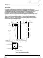
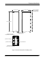
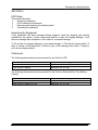
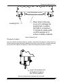
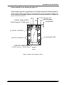
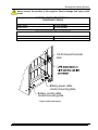
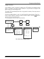
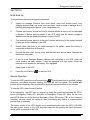
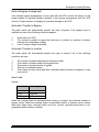
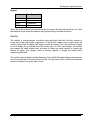
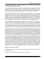
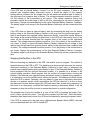
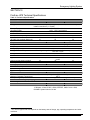
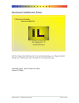
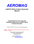
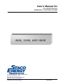
Figure 1 shows the UPS cabinet dimensions. Figure 2 shows the Battery Cabinet
dimensions. The 480 volt, 16 kW model uses two battery cabinets; all other systems
consist of the UPS and one battery cabinet.
32.38 [822.4mm]
23.00 [584.2mm]
31.94 [811.2mm]
6.00 [152.4mm] MIN.
WALL CLEARANCE
FOR VENTILATION
ESC
+
EPO
70.00 [1778.0mm]
INTAKE VENTILATION HOLES
EXTERNAL BATTERY CONTROL
CABLE ENTRY
2.25 [57.2mm] X 1.75 [44.5mm]
EXTERNAL BATTERY POWER CABLE ENTRY
2.25 [57.2mm] X 1.75 [44.5mm]
(2) SWIVEL CASTERS
(4) LEVELING FEET
(2) RIGID CASTERS
POWER CABLE ENTRY
7.25 [184.2mm] X 3.00 [76.2mm]
Figure 1- The FirstLine UPS 8–16 KW
Form No. 003-2287 Rev D
1
Emergency Lighting System
22.31 [566.7mm]
31.94 [811.2mm]
6.00 [152.4mm] MIN.
WALL CLEARANCE
FOR VENTILATION
70.00 [1778.0mm]
POWER CABLE ENTRY
3.25 [82.6mm] X 1.75 [44.5mm]
CUSTOMER CONNECTION
TERMINAL ACCESS
(2) SWIVEL CASTERS
(4) LEVELING FEET
(4) RIGID CASTERS
CONTROL CABLE ENTRY
2.25 [57.2mm] X 1.75 [44.5mm]
Figure 2- The FirstLine Extended Run Time Battery Cabinet
Form No. 003-2287 Rev D
2
Emergency Lighting System
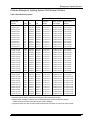
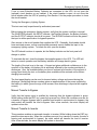
FirstLine Emergency Lighting System Part Number Scheme
Table 1-Part Numbering System
System Part
Number
Rating
Vin
Vout
UPS Part
Number
System Consists Of
Second Battery
Battery Cabinet
Cabinet Part
Part Number
Number
FLU924-8-20-N
8 kW
208/120Y
208/120Y
FLU-10T-20-1
FLU-BAT-20-2-N
(not required)
FLU924-8-20-B
8 kW
208/120Y
208/120Y
FLU-10T-20-1
FLU-BAT-20-2-B
(not required)
FLU924-8-20-N-I
8 kW
208 Delta
208/120Y
FLU-10T-20-1-I
FLU-BAT-20-2-N
(not required)
FLU924-8-20-B-I
8 kW
208 Delta
208/120Y
FLU-10T-20-1-I
FLU-BAT-20-2-B
(not required)
FLU924-8-42-N
8 kW
480/277Y
208/120Y
FLU-10T-42-1
FLU-BAT-20-2-N
(not required)
FLU924-8-42-B
8 kW
480/277Y
208/120Y
FLU-10T-42-1
FLU-BAT-20-2-B
(not required)
FLU924-8-42-N-I
8 kW
480 Delta
208/120Y
FLU-10T-42-1-I
FLU-BAT-20-2-N
(not required)
FLU924-8-42-B-I
8 kW
480 Delta
208/120Y
FLU-10T-42-1-I
FLU-BAT-20-2-B
(not required)
FLU924-8-44-N
8 kW
480/277Y
480/277Y
FLU-10T-44-1
FLU-BAT-20-2-N
(not required)
FLU924-8-44-B
8 kW
480/277Y
480/277Y
FLU-10T-44-1
FLU-BAT-20-2-B
(not required)
FLU924-8-44-N-I
8 kW
480 Delta
480/277Y
FLU-10T-44-1-I
FLU-BAT-20-2-N
(not required)
FLU924-8-44-B-I
8 kW
480 Delta
480/277Y
FLU-10T-44-1-I
FLU-BAT-20-2-B
(not required)
FLU924-12-20-N
12 kW
208/120Y
208/120Y
FLU-15T-20-1
FLU-BAT-20-3-N
(not required)
FLU924-12-20-B
12 kW
208/120Y
208/120Y
FLU-15T-20-1
FLU-BAT-20-3-B
(not required)
FLU924-12-20-N-I
12 kW
208 Delta
208/120Y
FLU-15T-20-1-I
FLU-BAT-20-3-N
(not required)
FLU924-12-20-B-I
12 kW
208 Delta
208/120Y
FLU-15T-20-1-I
FLU-BAT-20-3-B
(not required)
FLU924-12-42-N
12 kW
480/277Y
208/120Y
FLU-15T-42-1
FLU-BAT-20-3-N
(not required)
FLU924-12-42-B
12 kW
480/277Y
208/120Y
FLU-15T-42-1
FLU-BAT-20-3-B
(not required)
FLU924-12-42-N-I
12 kW
480 Delta
208/120Y
FLU-15T-42-1-I
FLU-BAT-20-3-N
(not required)
FLU924-12-42-B-I
12 kW
480 Delta
208/120Y
FLU-15T-42-1-I
FLU-BAT-20-3-B
(not required)
FLU924-12-44-N
12 kW
480/277Y
480/277Y
FLU-15T-44-1
FLU-BAT-20-3-N
(not required)
FLU924-12-44-B
12 kW
480/277Y
480/277Y
FLU-15T-44-1
FLU-BAT-20-3-B
(not required)
FLU924-12-44-N-I
12 kW
480 Delta
480/277Y
FLU-15T-44-1-I
FLU-BAT-20-3-N
(not required)
FLU924-12-44-B-I
12 kW
480 Delta
480/277Y
FLU-15T-44-1-I
FLU-BAT-20-3-B
(not required)
FLU924-16-20-N
16 kW
208/120Y
208/120Y
FLU-20T-20-2
FLU-BAT-20-3-N
(not required)
FLU924-16-20-B
16 kW
208/120Y
208/120Y
FLU-20T-20-2
FLU-BAT-20-3-B
(not required)
FLU924-16-20-N-I
16 kW
208 Delta
208/120Y
FLU-20T-20-1-I
FLU-BAT-20-2-N
FLU-BAT-20-2-N
FLU924-16-20-B-I
16 kW
208 Delta
208/120Y
FLU-20T-20-1-I
FLU-BAT-20-2-B
FLU-BAT-20-2-B
FLU924-16-42-N
16 kW
480/277Y
208/120Y
FLU-20T-42-1
FLU-BAT-20-2-N
FLU-BAT-20-2-N
FLU924-16-42-B
16 kW
480/277Y
208/120Y
FLU-20T-42-1
FLU-BAT-20-2-B
FLU-BAT-20-2-B
FLU924-16-42-N-I
16 kW
480 Delta
208/120Y
FLU-20T-42-1-I
FLU-BAT-20-2-N
FLU-BAT-20-2-N
FLU924-16-42-B-I
16 kW
480 Delta
208/120Y
FLU-20T-42-1-I
FLU-BAT-20-2-B
FLU-BAT-20-2-B
FLU924-16-44-N
16 kW
480/277Y
480/277Y
FLU-20T-44-1
FLU-BAT-20-2-N
FLU-BAT-20-2-N
FLU924-16-44-B
16 kW
480/277Y
480/277Y
FLU-20T-44-1
FLU-BAT-20-2-B
FLU-BAT-20-2-B
FLU924-16-44-N-I
16 kW
480 Delta
480/277Y
FLU-20T-44-1-I
FLU-BAT-20-2-N
FLU-BAT-20-2-N
FLU924-16-44-B-I
16 kW
480 Delta
480/277Y
FLU-20T-44-1-I
FLU-BAT-20-2-B
FLU-BAT-20-2-B
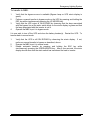
-B signifies that the battery cabinets are equipped with a disconnect breaker.
-N signifies that the battery cabinets are not equipped with a disconnect breaker and the
breaker must be provided externally as part of the installation.
-I signifies that the UPS has an input isolation transformer and does not require an input neutral.
Form No. 003-2287 Rev D
3
Emergency Lighting System
SECTION 2
Safety Warnings
IMPORTANT SAFETY INSTRUCTIONS
SAVE THESE INSTRUCTIONS
This manual contains important instructions that you should follow during installation and
maintenance of the UPS and batteries. Please read all instructions before operating the
equipment and save this manual for future reference.
READ AND FOLLOW ALL SAFETY INSTRUCTIONS
Do not use outdoors.
Do not route wiring across or near hot surfaces.
Do not install near gas or electric heaters.
Use caution when servicing batteries. Battery acid can cause burns to skin and
eyes. If acid is spilled on skin or in eyes, flush acid with fresh water and contact
a physician immediately.
e. Equipment should be installed where it will not readily be subjected to tampering
by unauthorized personnel.
f. The use of accessory equipment not recommended by the manufacturer may
cause an unsafe condition.
g. Do not use this equipment for other than intended use.
a.
b.
c.
d.
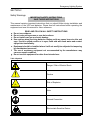
Table 2-Symbols
Danger / Risk of Electric Shock
Caution
Risk of Explosion
Note
Ground Connection
Electrostatic Sensitive Device
Form No. 003-2287 Rev D
4
Emergency Lighting System
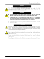
DANGER
This UPS contains LETHAL VOLTAGES. All repairs and service should be
performed by AUTHORIZED SERVICE PERSONNEL ONLY. There are NO
USER SERVICEABLE PARTS inside the UPS.
WARNING
This UPS contains its own energy source (batteries). The UPS output may
carry live voltage even when the UPS is not connected to an AC supply.
To reduce the risk of fire or electric shock, install this UPS in a temperature
and humidity controlled, indoor environment, free of conductive contaminants.
Do not operate near water or excessive humidity (95% maximum).
Input and output over-current protection and disconnect switches must be
provided by others.
CAUTION
Batteries can present a risk of electrical shock or burn from high short circuit
current. Observe proper precautions. Servicing should be performed by qualified
service personnel knowledgeable of batteries and required precautions. Keep
unauthorized personnel away from batteries.
Risk of explosion if batteries are replaced by an incorrect type. Replace with same
type and rating only.
Proper disposal of batteries is required. Refer to your local codes for disposal
requirements.
Never dispose of batteries in a fire. Batteries may explode when exposed to flame.
Form No. 003-2287 Rev D
5
Emergency Lighting System
SECTION 3
UPS Setup
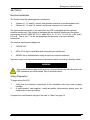
This section describes:
Equipment inspection
Floor loading and clearances
Removing and replacing the cabinet panels
Unloading the cabinet(s)
Inspecting the Equipment
If any equipment has been damaged during shipment, keep the shipping and packing
materials for the carrier or place of purchase and file a claim for shipping damage. If you
discover damage after acceptance, file a claim for concealed damage.
To file a claim for shipping damage or concealed damage: 1) File with the carrier within 15
days of receipt of the equipment, 2) Send a copy of the damage claim within 15 days to
your service representative.
Clearances
The following clearances are recommended for the FirstLine UPS.
From Front of Cabinet
From Back of Cabinet
From Side of Cabinet
36” (91.4 cm) working space
6” (15.2 cm)
Minimum 24” (61 cm)
The following clearances are recommended for the FirstLine Extended Run Time Battery
Cabinet.
From Front of Cabinet
From Back of Cabinet
From Side of Cabinet to UPS
Form No. 003-2287 Rev D
36” (91.4 cm) working space
6” (15.2 cm)
Minimum 24” (61 cm)
6
Emergency Lighting System
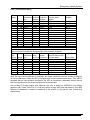
Floor Loading
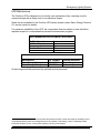
When planning the installation, consider the Emergency Lighting System’s weight for floor
loading. The strength of the installation surface must be adequate for point and distributed
loading. The approximate weights are shown in the following table.
Table 3-Model Floor Loadings
UPS Cabinet
Maximum
Weight
Battery Cabinet(s)
Point
Maximum
Loading
Weight
Point
Loading
System Part
Number
Rating
Vin
Vout
Lbs
kg
Lbs/in2
kg/cm2
Lbs
kg
Lbs/in2
kg/cm2
FLU924-8-20-N
8 kW
208/120Y
208/120Y
1024
464
326
23
1385
628
441
31
FLU924-8-20-B
8 kW
208/120Y
208/120Y
1024
464
326
23
1385
628
441
31
FLU924-8-20-N-I
8 kW
208/120Y
208/120Y
1314
596
418
29
1385
628
441
31
FLU924-8-20-B-I
8 kW
208/120Y
208/120Y
1314
596
418
29
1385
628
441
31
FLU924-8-42-N
8 kW
480/277Y
208/120Y
1200
544
382
27
1385
628
441
31
FLU924-8-42-B
8 kW
480/277Y
208/120Y
1200
544
382
27
1385
628
441
31
FLU924-8-42-N-I
8 kW
480/277Y
208/120Y
1335
606
425
30
1385
628
441
31
FLU924-8-42-B-I
8 kW
480/277Y
208/120Y
1335
606
425
30
1385
628
441
31
FLU924-8-44-N
8 kW
480/277Y
480/277Y
1485
674
473
33
1385
628
441
31
FLU924-8-44-B
8 kW
480/277Y
480/277Y
1485
674
473
33
1385
628
441
31
FLU924-8-44-N-I
8 kW
480/277Y
480/277Y
1620
735
516
36
1385
628
441
31
FLU924-8-44-B-I
8 kW
480/277Y
480/277Y
1620
735
516
36
1385
628
441
31
FLU924-12-20-N
12 kW
208/120Y
208/120Y
1024
464
326
23
1919
870
611
43
FLU924-12-20-B
12 kW
208/120Y
208/120Y
1024
464
326
23
1919
870
611
43
FLU924-12-20-N-I
12 kW
208/120Y
208/120Y
1314
596
418
30
1919
870
611
43
FLU924-12-20-B-I
12 kW
208/120Y
208/120Y
1314
596
418
30
1919
870
611
43
FLU924-12-42-N
12 kW
480/277Y
208/120Y
1200
544
382
27
1919
870
611
43
FLU924-12-42-B
12 kW
480/277Y
208/120Y
1200
544
382
27
1919
870
611
43
FLU924-12-42-N-I
12 kW
480/277Y
208/120Y
1335
606
425
30
1919
870
611
43
FLU924-12-42-B-I
12 kW
480/277Y
208/120Y
1335
606
425
30
1919
870
611
43
FLU924-12-44-N
12 kW
480/277Y
480/277Y
1485
674
473
33
1919
870
611
43
FLU924-12-44-B
12 kW
480/277Y
480/277Y
1485
674
473
33
1919
870
611
43
FLU924-12-44-N-I
12 kW
480/277Y
480/277Y
1620
735
516
36
1919
870
611
43
FLU924-12-44-B-I
12 kW
480/277Y
480/277Y
1620
735
516
36
1919
870
611
43
FLU924-16-20-N
16 kW
208/120Y
208/120Y
1558
707
496
35
1919
870
611
43
FLU924-16-20-B
16 kW
208/120Y
208/120Y
1558
707
496
35
1919
870
611
43
FLU924-16-20-N-I
16 kW
208/120Y
208/120Y
1314
596
418
30
1385
628
441
31
FLU924-16-20-B-I
16 kW
208/120Y
208/120Y
1314
596
418
30
1385
628
441
31
FLU924-16-42-N
16 kW
480/277Y
208/120Y
1200
544
382
27
1385
628
441
31
FLU924-16-42-B
16 kW
480/277Y
208/120Y
1200
544
382
27
1385
628
441
31
FLU924-16-42-N-I
16 kW
480/277Y
208/120Y
1335
606
425
30
1385
628
441
31
FLU924-16-42-B-I
16 kW
480/277Y
208/120Y
1335
606
425
30
1385
628
441
31
FLU924-16-44-N
16 kW
480/277Y
480/277Y
1485
674
473
33
1385
628
441
31
FLU924-16-44-B
16 kW
480/277Y
480/277Y
1485
674
473
33
1385
628
441
31
FLU924-16-44-N-I
16 kW
480/277Y
480/277Y
1620
735
516
36
1385
628
441
31
FLU924-16-44-B-I
16 kW
480/277Y
480/277Y
1620
735
516
36
1385
628
441
31
Please note that there are two Battery Cabinets for all 16 kW Systems except the FLU924-16-20-N
and the FLU924-16-20-B. All other Systems use just one Battery Cabinet. Refer to Table 1.
Form No. 003-2287 Rev D
7
Emergency Lighting System
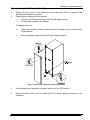
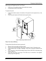
Unloading the Cabinet(s)
The following tools are required for unloading the cabinet(s):
Wrenches for 1/4” bolts and 1/2” nut
Forklift
CAUTION
The UPS and Battery cabinets are heavy (see Table 3). Unloading the cabinets
requires at least two people to safely remove the cabinets from the pallet.
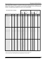
To remove the UPS or Battery cabinets from the ship pallet:
1.
2.
3.
Remove all banding, wrapping, and foam protectors.
Loosen the six 1/2” nuts and washers securing the shipping brackets to the pallet
(see Figures 3 and 4).
Remove and discard the four 1/4” bolts and washers securing the shipping brackets
to the cabinet side panels, also remove the four ¼” bolts and washers the brackets
surrounds but does not touch. Save these as they must be reinstalled later. Pull the
brackets away from the cabinet..
Forklift access
from rear
Pallet
Shipping bracket - (1) this
side and opposite side
Figure 3-UPS on pallet
Form No. 003-2287 Rev D
8
Emergency Lighting System
Remove and discard
1/4" bolt and washers
(4) places
Remove (4) 1/4" bolts.
Reinstall after the unit is on the floor
Pull (2) shipping brackets
away from cabinet.
Loosen (3) 1/2" nuts on each bracket
Remove (4) 1/4" bolts.
Remove and discard
Reinstall after the unit is on the floor
1/4" bolt and washers
(4) places
Figure 4-Shipping Bracket
4.
5.
6.
7.
8.
9.
10.
11.
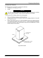
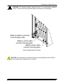
Remove the front cover (see Figure 12) before inserting the lifting forks.
Ensure that the four (4) leveling feet are raised so that they will not touch the floor
when the cabinet is placed on the floor.
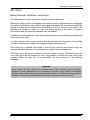
Lift the cabinet with a forklift from the rear of the unit, one to two inches (1”-2” [2.55cm]) above the pallet (see figure 5).
Slide the pallet completely away from the raised cabinet.
Slowly lower the cabinet to the floor.
Reinstall the front cover and (4) ¼” bolts and washers (see figure 4).
Roll the cabinet to the desired location.
Do not move the cabinet to another location by forklift as the cabinets are heavy and
may fall.
DO NOT ALLOW THE FORKLIFT TO MOVE WHILE THE CABINET IS RAISED,
ONLY MOVE THE CABINET VERTICALLY TO REMOVE THE PALLET FROM
UNDER THE CABINET
Form No. 003-2287 Rev D
9
Emergency Lighting System
13.00" [330mm] Max. on UPS
10.00" [254mm] Max. on Battery
Leveling foot
Place forks in this area
so as not to damage the
leveling feet or casters.
Set forks to a maximum
13 inches at outside width
on UPS cabinets & 10
inches on battery cabinets.
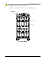
Figure 5-Lifting fork area
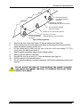
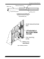
Placing the Cabinet
Once the cabinet has been rolled into position, remove the front panel to access the front
leveling feet by pulling the panel outward at the bottom of the unit until it unsnaps and then
lift up and off the cabinet (see figure 9). Adjust the leveling feet as shown in figure 6.
Lower the leveling foot
to the floor to secure
the UPS in position
Figure 6-Leveling foot being adjusted down to the floor
Form No. 003-2287 Rev D
10
Emergency Lighting System
SECTION 4
Electrical Installation
The FirstLine has the following power connections:
3-phase (L1, L2, andL3), neutral, and ground connection for rectifier/bypass input
3-phase (L1, L2, and L3), neutral, and ground connection for load output
The input neutral connection is not used when the UPS is equipped with the optional
isolation transformer. If the system is equipped with an isolation transformer, the system
part number will be FLU924-XX-YY-Z-I, where XX is 16, 12, or 8; YY is 20, 42, or 44; and Z
is N or B. That is, the "-I" at the end designates the presence of an input isolation
transformer.
The nominal input/output voltages are:
120/208 VAC
480V, 60 Hz input is available when using an input transformer.
480/480 Vac is available when using an input and output transformer.
Input and output overcurrent protection and disconnect switch must be provided by others.
WARNING
Only qualified service personnel (such as a licensed electrician) should perform the
UPS installation and initial startup. Risk of electrical shock.
Wiring Preparation
To begin wiring the UPS:
1.
2.
Verify that the electrical connections to the installation site have been properly
installed.
A wall-mounted, user-supplied, readily-accessible disconnection device must be
incorporated in the input wiring.
Compare the circuit breaker ratings to the ones in Table 6 on page 14.
Form No. 003-2287 Rev D
11
Emergency Lighting System
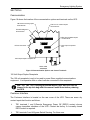
3.
4.
5.
6.
Switch off utility power to the distribution point where the UPS will be connected. Be
absolutely sure there is no power.
Determine your equipment’s grounding requirements according to your local
electrical code.
Remove the UPS rear panel.
Conduit landing plates are located at the rear bottom of the base to accommodate
bottom wire entry to the cabinet (see Figure 7).
Remove plate and drill or punch hole to fit conduit bushing with Greenlee punch or similar
device. Make certain that the bushing will be clear in the opening in the base. Mount
bushing to plate and tighten to manufacturer’s recommendations. Replace the plate and
mount conduit.
FRONT
EXTERNAL BATTERY CONTROL
CABLE ENTRY
2.25 [57.2mm] X 1.75 [44.5mm]
EXTERNAL BATTERY POWER
CABLE ENTRY
2.25 [57.2mm] X 1.75 [44.5mm]
4.75 [120.7mm]
4.75 [120.7mm]
2.12 [54.0mm]
(2) SWIVEL CASTERS
(2) RIGID CASTERS
(4) LEVELING FEET
.81 [20.6mm]
POWER CABLE ENTRY
7.25 [184.2mm] X 3.00 [76.2mm]
4.75 [120.7mm]
REAR
Figure 7-Bottom View
Form No. 003-2287 Rev D
12
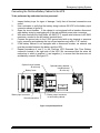
Emergency Lighting System
Wiring Installation
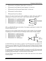
1.
2.
3.
4.
Unscrew and remove the rear panel.
Connect the input wires to the proper terminals shown in Figure 8. Insure proper
phase rotation.
Connect the output wires to the proper terminals shown in Figure 8.
Replace the rear panel.
A
B
C
INPUT
N
A
B
C
OUTPUT
N
NOTICE
FOR SUPPLY CONNECTIONS,
USE WIRES SUITABLE FOR AT
LEAST 75°C
Figure 8-Terminal Blocks
Table 4-Input/Output Terminal
INPUT/OUTPUT TERMINAL TIGHTENING TORQUE
#2/0 - #6 AWG
#8 - #12 AWG
120 inch-pounds
50 inch-pounds
Table 5-Ground Lugs
GROUND LUGS TIGHTENING TORQUE
#10 AWG
#8 AWG
#4 - #6 AWG
#1/0 - #2 AWG
Form No. 003-2287 Rev D
35 inch-pounds
40 inch-pounds
45 inch-pounds
50 inch-pounds
13
Emergency Lighting System
Table 6-FirstLine UPS 8, 12, 16 KW Current Requirements
UPS
Rating
Input
Voltage
8 KW
8 KW
208 V
480 V
Max. Input
Current (A)
Allowed for
Specified
Branch
Protector
32
14
12 KW
12 KW
208 V
480 V
47
21
60
30
16 KW
16 KW
208 V
480 V
63
28
80
35
UPS
Rating
Output
Voltage
40
20
8 KW
8 KW
208 V
480 V
22
10
Maximum
Allowable
Circuit
Protection
(A)
(note 1)
35
12 KW
12 KW
208 V
480 V
33
15
(note 1)
35
16 KW
16 KW
208 V
480 V
44
19
(note 1)
Note 1:
Rated Max.
Output Current
(A)
Maximum
Allowable Branch
Circuit Protection
(A)
Output circuit protection requirement determined by distribution circuit.
Form No. 003-2287 Rev D
14
Emergency Lighting System
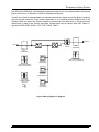
Wiring Specifications and Diagrams
Note: Unless the system is a "-I" model with an input isolation transformer, the
input neutral must be wired for proper operation or the UPS will not start. The
input neutral must be grounded at the source. If an input isolation transformer is
present, the input neutral is not used and no input neutral wire needs to be
provided. The neutral of the isolation transformer is bonded to ground at the
UPS. The UPS chassis must be grounded to the source via a grounding
conductor per Table 7.
Note: Do not over-tighten the screws; be sure to use the specified tightening
torque values shown in Table 4, Table 5, and Table 8.
8KW, 208V:
CAUTION to reduce the risk of fire, connect only to a circuit provided with
40 amperes maximum branch circuit protection in accordance with the
National Electrical Code, ANSI/NFPA 70.
8 KW, 480V:
CAUTION to reduce the risk of fire, connect only to a circuit provided with
20 amperes maximum branch circuit protection in accordance with the
National Electrical Code, ANSI/NFPA 70.
12 KW, 208V:
CAUTION to reduce the risk of fire, connect only to a circuit provided with
60 amperes maximum branch circuit protection in accordance with the
National Electrical Code, ANSI/NFPA 70.
12 KW, 480V
CAUTION to reduce the risk of fire, connect only to a circuit provided with
30 amperes maximum branch circuit protection in accordance with the
National Electrical Code, ANSI/NFPA 70.
16 KW, 208V
CAUTION to reduce the risk of fire, connect only to a circuit provided with
80 amperes maximum branch circuit protection in accordance with the
National Electrical Code, ANSI/NFPA 70.
16 KW, 480V:
CAUTION to reduce the risk of fire, connect only to a circuit provided with
35 amperes maximum branch circuit protection in accordance with the
National Electrical Code, ANSI/NFPA 70.
Form No. 003-2287 Rev D
15
Emergency Lighting System
Table 7 Terminal Block Wiring
UPS
Voltage Input
Phase
Neutral
Rating
Transformer Conductor Conductor
Type
Min/Max Min/Max
10kva 208/120 NA
#8/2-0
#8/2-0
208 isolation
#8/2-0
(none)
480/277 auto
#10/2-0 #10/2-0
480 isolation
#10/2-0 (none)
Neutral Conductor with
non-linear loads
Min/Max
#6/2-0
(none)
#8/2-0
(none)
Ground Wire
Min/Max
15kva
208/120 NA
208 isolation
480/277 auto
480 isolation
#6/2-0
#6/2-0
#8/2-0
#8/2-0
#6/2-0
(none)
#8/2-0
(none)
#4/2-0
(none)
#6/2-0
(none)
#8/1-0
#8/1-0
#8/1-0
#8/1-0
20kva
208/120 NA
208 isolation
480/277 auto
480 isolation
#4/2-0
#4/2-0
#8/2-0
#8/2-0
#4/2-0
(none)
#8/2-0
(none)
#2/2-0
(none)
#6/2-0
(none)
#6/1-0
#6/1-0
#6/1-0
#6/1-0
#8/1-0
#8/1-0
#8/1-0
#8/1-0
OUTPUT-Minimum wire size required to support rated load. Smaller wire may be used if rated
load current is not needed and the appropriate circuit protection is applied.
Output
UPS
Transformer Phase
Neutral
Neutral Conductor with
Rating Voltage Type
Conductor Conductor non-linear loads
Ground Wire
10 kVA 208/120 NA
#10
#10
#8
#8/1-0
480/277 auto
#12
#12
#10
#8/1-0
15 kVA 208/120 NA
480/277 auto
#8
#10
#8
#10
#6
#8
#8/1-0
#8/1-0
20 kVA 208/120 NA
480/277 auto
#6
#10
#6
#10
#4
#8
#6/1-0
#6/1-0
Note: No output circuit protection is required if the output conductor sizes are at least as large as
the input conductors, unless the UPS is equipped with an input isolation transformer. If the UPS is
equipped with an input isolation transformer, the UPS is considered a separately derived source
and circuit protection for the output conductors must be provided.
Use at least 75°C-rated copper wire. Minimum wire size is based on 120/208 full load ratings
applied to NEC Code Table 310-16. Code may require a large AWG size than shown in this table
because of temperature, number of conductors in the conduit, or long service runs. Follow local
requirements.
Form No. 003-2287 Rev D
16
Emergency Lighting System
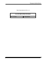
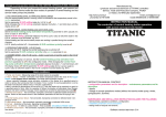
Per NEC article 300-20(2), all three-phase conductors must be run in the same conduit. Neutral and
ground must be run in the same conduit as the phase conductors.
Conduit to be sized to accommodate one neutral conductor the same size as the phase conductor
and one ground conductor. If two neutral conductors or an oversized neutral conductor are to be
installed, check the size of the conduit needed to accommodate the extra wire or size and use that
conduit size in place of the conduit size listed. Conduit sizes can be chosen from NEC Table C1,
type letters RHH, RHW, RHW-2, TW, THW, THHW, THW-2.
OUTPUT
INPUT
STATIC
SWITCH
INVERTER
RECTIFIER
208Y
(STANDARD)
208Y
(STANDARD)
+
-
BATTERY
(STANDARD)
TRANSFORMER
(480V OUTPUT MODELS)
AUTOTRANFORMER
(480V INPUT MODELS)
+
-
EXTENDED
BATTERY
(SOME MODELS)
ISOLATION
TRANSFORMER
(OPTION)
(208 )
(480 )
+
-
EXTERNAL
BATTERY(S)
Figure 9-Wiring Single Line Diagram
Form No. 003-2287 Rev D
17
Emergency Lighting System
To begin wiring the Battery Cabinet(s)
1.
2.
Switch off utility power to the distribution point where the UPS is connected. Be
absolutely sure there is no power.
Removing and replacing the front panel:
Pull the top of the panel outward until the ball studs unsnap.
Lift the panel up and off the cabinet.
To replace the panel:
Lower the shoulder screws at the bottom of the panel into the keyhole slots
on the cabinet.
Press the panel inward until the ball studs snap into place.
Figure 10- Removing the Battery Cabinet Front Panel
3.
If the optional circuit breaker is included, switch it to the “Off” position.
4.
Remove the inner front cover by removing the (12) twelve screws mounting it to the
enclosure.
Form No. 003-2287 Rev D
18
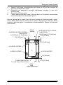
5.
Emergency Lighting System
Conduit landing plates are located at the front bottom of the base to accommodate
bottom wire entry to the cabinet (see figure 10).
Remove plates and drill or punch hole to fit conduit bushing with Greenlee punch or
similar device. Make certain that the bushing will be clear in the opening in the base.
Mount bushing to plate and tighten to manufacturer’s recommendations. Replace the
plates and mount conduit.
7.00 [177.8mm] TYP.
6.03 [153.2mm]
POWER CABLE ENTRY
2.12 [54.0mm]
3.25 [82.6mm] X 1.75 [44.5mm]
(2) SWIVEL CASTERS
(4) LEVELING FEET
(4) RIGID CASTERS
CONTROL CABLE ENTRY
2.25 [57.2mm] X 1.75 [44.5mm]
REAR
Figure 11-Bottom View, Battery Cabinet
Form No. 003-2287 Rev D
19
Emergency Lighting System
Removing and Replacing the Front Panel
1.
2.
Pull the top of the panel outward until the ball studs unsnap.
Lift the panel up and off the cabinet.
To replace the panel:
1.
2.
Lower the shoulder screws at the bottom of the panel into the keyhole slots on the
cabinet.
Press the panel inward until the ball studs snap into place.
KEYHOLE SLOT
SHOULDER SCREW
BALL STUD CATCH
Figure 12-Removing the UPS Front Panel
Check the Internal Battery
To be performed by authorized service personnel:
1.
2.
3.
4.
5.
Remove front cover panel and interior panel.
Remove and discard shipping support panel mounted in front of the battery trays.
Inspect battery trays for signs of damage. Verify that all terminal connections are
sound.
Use a voltmeter to verify that the battery string is above 420 VDC at the battery plug
shown in figure 13.
Verify that the positive (red) plug of the lower tray is connected to the negative
(black) plug of the upper tray.
Form No. 003-2287 Rev D
20
Emergency Lighting System
Never connect the positive red (red) plug to the negative (black) plug from the
same tray. Severe damage and injury could result.
6.
7.
If the UPS has four battery trays, also check the lower two battery trays.
Connect the external battery to the UPS, using the procedure that follows.
Battery fuse
DC input plug
Inverter fuse
Black
!
Red
Battery plug
Blue plug
Figure 13-Internal Battery
Form No. 003-2287 Rev D
21
Emergency Lighting System
Connecting the FirstLine Battery Cabinet to the UPS
To be performed by authorized service personnel:
1.
2.
3.
4.
5.
6.
7.
Inspect battery trays for signs of damage. Verify that all terminal connections are
sound.
Use a voltmeter to verify that the battery string is above 408 VDC at the battery input
connector shown in figure 14.
Open the circuit breaker. If the cabinet is not equipped with a breaker disconnect
each battery string by unplugging all of the red and black power pole connectors.
With wire sized per the local codes, #6 AWG 75°C copper wire minimum to #2 AWG
maximum, connect to the left battery terminal block.
Connect the ground wire to the 1/4-20 ground stud with a ring terminal or pressure
lug by removing and replacing the top nut and washers only with a 7/16” wrench.
If the battery cabinet is not equipped with a disconnect breaker, an external one
must be provided between the battery and the UPS.
Repeat procedures 4 and 5 to the FirstLine UPS Extended Run Time Battery
connector located in the right side of the UPS. We recommend that the wires be
marked as to which is positive (+) and negative (-) to ensure that the wires are not
accidentally crossed. See figure 15.
Optional circuit breaker
-B units only
Battery fuses
Optional battery breaker
interface board
-B units only
AUX.
SHUNT
CONTACT TRIP
J4
J5
J3
BATTERY
J1
J2
IN
OUT
BATTERY
DO NOT DISCONNECT
UNDER LOAD
NOTICE
FOR SUPPLY CONNECTIONS,
USE WIRES SUITABLE FOR AT
LEAST 75°C
USE COPPER
CONDUCTORS ONLY
Battery input connector
Ground connection
Battery output connector
to next battery cabinet
Figure 14-Input/Output Panel
Form No. 003-2287 Rev D
22
Emergency Lighting System
Never connect the positive to the negative. Severe damage and injury could
result.
BATTERY INPUT/OUTPUT TERMINAL
TIGHTENING TORQUE
#2-#3 AWG
#4-#6 AWG
50 inch-pounds
45 inch-pounds
GROUND STUD TIGHTENING TORQUE
Extended Run Time Battery Cabinet
UPS Cabinet
100 inch-pounds
55 inch-pounds
1/4-20 Ground terminal
stud
Battery power cable
conduit mounting plate
Battery control cable
conduit mounting plate
Figure 15-UPS Connections
Form No. 003-2287 Rev D
23
Emergency Lighting System
Battery Connection, continued
8. If the system has two battery cabinets, prepare the second battery cabinet by removing
the panels. Repeat steps 1 through 7 for the second cabinet. The other end of the wires
from the second cabinet connect to the right-hand battery terminal block using the
procedure described in steps 4 and 5.
9. If the battery cabinet is equipped with the optional circuit breaker, connect the breaker
interface cable(s) as described in Section 5 of this manual, then return to this procedure.
10. If the battery cabinet does not have an internal breaker, close the external breaker. Do
not close the internal breaker at this time. Connect the internal battery of the UPS by
connecting the red and black battery plug to the red and black dc input plug. Refer to
Figure 13. If the UPS has twp internal batteries, also connect the second battery plug to
the second dc input plug.
11. Referring to figure 14, at the external battery cabinet, measure the dc voltage from the
left-hand fuse (positive lead of meter) to the right-hand fuse (negative lead of meter). The
voltage measured should be positive. If not, the polarity of the battery connections is not
correct and must be corrected. Expect to measure 400 to 445 Vdc during this test,
depending on the state of charge of the battery. Repeat this test for the second battery
cabinet, if present.
12. If the battery polarity is correct, open the external breaker (if equipped) and connect all
of the internal red and black power pole battery connectors in both battery cabinets.
13. Install the internal covers on both battery cabinets and on the UPS.
Warning: batteries must be connected to the UPS before the rectifier is started. (The
rectifier starts automatically when the UPS is turned on). All battery breakers must be
closed prior to starting the UPS. If a battery breaker is opened for any reason, the UPS
must be turned off before closing the breaker. Refer to section 9 for additional information.
14. Close the internal breakers and/or external breakers for the battery cabinets.
15. The UPS is now ready to be started. The outer covers can be installed as desired.
Form No. 003-2287 Rev D
24
Emergency Lighting System
SECTION 5
Circuit breaker interface
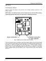
Figure 16 shows the location of the optional circuit breaker interface connectors in the
Battery Cabinet.
NOTE: Wires to the battery breaker interface board must not enter the UPS or battery
cabinet through the same port as the input/output or battery power wires.
AUX.
SHUNT
CONTACT TRIP
J4
J5
J3
Input connector
J1
J2
IN
OUT
Output connector
to next cabinet
Figure 16-Battery Breaker Interface Board Assembly
If the circuit breaker option is included in the battery cabinet, attach one end of the provided
6 pin circular din molded cable to the input connector of the battery breaker interface board,
see figure 16. Attach the opposite end of the cable to the J1 battery breaker connector
cable located in the front lower left of the UPS, see figure 17. If more than one battery
cabinet is used, connect the additional cable from the J2 output connector on the battery
breaker interface board in the first cabinet to the J1 input connector in the second cabinet
and so on.
Form No. 003-2287 Rev D
25
Emergency Lighting System
CAUTION: The battery breaker interface board is an electrostatic sensitive
device. The user should be grounded when connecting to this assembly.
Battery breaker connector
in the Firstline UPS
Battery control cable
conduit mounting plate
Battery power cable
conduit mounting plate
Figure 17-Battery Breaker Connector
CAUTION: If the optional circuit breaker trips, the internal batteries of the UPS are
still connected and providing power to the UPS.
Form No. 003-2287 Rev D
26
Emergency Lighting System
SECTION 6
Communication
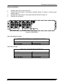
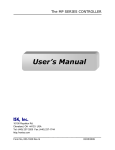
Figure 18 shows the location of the communication options and terminals on the UPS.
TB2 Contact sensing inputs
terminal block
TB3 Form C contact outputs
terminal block
TB1 REPO/Bypass
terminal block
1
2
3
4
1
2
3
4
5
6
7
8
9 10
1
2
3
4
5
6
7
8
9 10 11 12 13 14 15
1
2
3
4
5
6
7
8
9 10
RS-232 Connector
TB4 Opto-isolated outputs
terminal block
120V Output receptacle
fuse
FUS E
120V Output duplex receptacle
REAR VIEW
Figure 18-Communication Options and Control Terminals
120 Volt Output Duplex Receptacle
The 120 volt receptacle is only to be used to power Staco supplied communications
equipment. It is imperative that no other loads be connected to this receptacle.
Note: TB1, TB2, TB3, TB4 plug-in terminal blocks, fuse, and fuse cap are
shipped in the zip-lock bag with this manual. Install them before powering
up the UPS.
Customer Interface
The Customer Interface is located on the rear cover of the UPS. There are seven dry
contact inputs that function as follows:
TB1 terminals 1 and 2-Remote Emergency Power Off (REPO) contact closure
causes immediate shutdown of the UPS. Contact the factory if a normally closed
REPO switch is required.
TB1 terminals 3 and 4-Bypass Switch Sensing. For future use.
Form No. 003-2287 Rev D
27
Emergency Lighting System
TB2 terminals 1 and 2-Battery Charge Inhibit. For future use.
TB2 terminals 3 and 4-Reduced Current Operation. For future use.
TB2 terminals 5 and 6-Automaitc Restart Inhibit. For future use.
TB2 terminals 7 and 8-not defined.
TB2 terminal 9 and 10-not defined.
There are five sets of form-C dry contact available as outputs. They are capable of
switching up to 30 volts (AC or DC) at up to 1 amp. Listed in order of NO, COM, NC.
TB3 terminals 1, 2, 3 – running on inverter.
TB3 terminals 4, 5, 6- battery discharging.
TB3 terminals 7, 8, 9- low battery reserve.
TB3 terminals 10, 11, 12- on bypass.
TB3 terminals 13, 14, 15- alarm present.
1
2
Example
3
Figure 19 TB3
TB3
J232 is an RS-232 DCE three wire interface. See separate specification for details. (Not
currently enabled-future use).
There are five sets of optically isolated open collector outputs available. They are capable
of switching up to 30 volts DC and up to 3 milliamps. Listed in order of Emitter, Collector.
TB4 terminals 1,2 – running on inverter
TB4 terminals 3,4 – battery discharging
TB4 terminals 5,6 – low battery reserve
TB4 terminals 7,8 – on bypass
TB4 terminals 9, 10 – alarm present
Vcc = 5.0 VDC
RL
2
1
Vo
Typical
application
TB4
Figure 20-TB4
An RS-232 DCE three wire interface is available. The UPS shipped with an installation CD
containing monitor software and an RS-232 cable. The monitor software will allow a single
user to connect the UPS to a computer via the RS-232 port for local monitoring of UPS
operation.
For advanced monitoring Ethernet and SNMP are supported via the RS-232 interface with
an external adaptor. A 120 volt AC outlet has been provided on the back panel of the UPS
for powering the external adaptor. Consult the factory for more details.
The local RS-232 monitor function cannot be used at the same time as the external
monitoring adaptor.
Form No. 003-2287 Rev D
28
Emergency Lighting System
Table 8-Torque Values for TB1, 2, 3, 4
TORQUE VALUES FOR TERMINAL BLOCKS
ON CUSTOMER INTERFACE BOARD
#22 - #12 AWG
Form No. 003-2287 Rev D
4.4 inch-pounds
29
Emergency Lighting System
SECTION 7
Operation
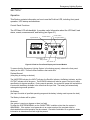
This Section contains information on how to use the FirstLine UPS, including front panel
operation, UPS startup and shutdown.
Control Panel Functions
The UPS has LCD with backlight. It provides useful information about the UPS itself, load
status, events, measurements, and setting (see figure 21).
Bypass Indicator
Inverter Indicator
On Bypass Indicator
Rectifier Indicator
ESC
+
EPO
Input Indicator
Battery Indicator
Alarm Indicator
Output Indicator
Figure 21-FirstLine Front Panel Display and Control Module
To assure that the Emergency Lighting System is functioning properly, observe the front panel
display on the UPS. There are three conditions that could exist:
System Normal
(everything is working as desired)
The INVERTER indicator, the INPUT indicator, the Rectifier Indicator, the Battery Indicator, and the
OUTPUT indicator will all be green. The BYPASS indicator will also be green if the input is within
specification for bypass operation. During normal operation, the system will power the load with the
inverter with the battery available in the event that the input fails. The battery will automatically
recharge during normal operation.
On Battery
(the input is outside of specified operating range and the battery is being used to power the load)
The Battery Indicator will be yellow.
Abnormal
(the system is running on bypass or there is a fault)
If neither the SYSTEM NORMAL nor the ON BATTERY condition exists, then the system is
ABNORMAL. If the system is on bypass due to an output overload, the overload must be
eliminated before normal operation can be restored. Use table 9 and table 10 as guides to obtain
information to determine what fault might be present.
Form No. 003-2287 Rev D
30
Emergency Lighting System
The following table shows the indicator status and description:
Indicator
Status
Description
Bypass
Bypass
Bypass
Bypass
Off
Green
Yellow
Red
Bypass input voltage or frequency not qualified
Bypass input voltage or frequency qualified
Inverter output not synchronized to bypass input
Bypass input voltage has incorrect phase sequence
Input
Input
Input
Off
Green
Red
Rectifier input voltage or frequency not qualified
Rectifier input voltage and frequency qualified
Rectifier input voltage has incorrect phase sequence
Rectifier
Rectifier
Rectifier
Rectifier
Off
Green
Yellow
Red
System OFF or Rectifier input not qualified
Rectifier is running normally
Rectifier is running at input power limit
Rectifier failure or DC Bus Fault, call for Service
Battery
Battery
Battery
Battery
Off
Green
Yellow
Red
System OFF
Battery is being charged or is at full charge
Battery is discharging
Battery fault or no battery present
Inverter
Inverter
Inverter
Inverter
Off
Green
Yellow
Red
System OFF or on Bypass
Running ON INVERTER (normal mode)
Bus voltage out of range or tripped on over current
Inverter failure, call for service
On Bypass
On Bypass
On Bypass
Off
Green
On Bypass
Red
System OFF or not on Bypass (normal mode)
ON Bypass
On Bypass, overload present, reduce load before system
shuts down
Static Switch Failure, Do Not Operate UPS, call for Service
Output
Output
Output
Output
Off
Green
Yellow
Red
System off
Output is present (On Inverter or on Bypass)
Output is overloaded, reduce load before system shuts down
Output failed or EPO was activated or REPO was activated
Alarm
Alarm
Off
Yellow
No alarms are present
An alarm is present
Yellow
Table 9-Indicator Status and Description
Form No. 003-2287 Rev D
31
Emergency Lighting System
Display Functions
As the default or after 15 minutes of inactivity, the LCD displays the selectable startup
screen. The default is the Staco Energy Products Co. logo and can be changed to the
Mimic screen in the User Settings menu.
The backlit LCD automatically dims after a long period of inactivity. Press any button to
restore the screen.
Use the two middle buttons (↑ and ↓) to scroll through the menu structure. Press the →
button to enter a submenu. Press the button to select an option. Press the ESC button to
cancel or return to the previous menu.
The following table shows the basic menu structure.
>
>
Staco Energy Products
Alarms
Logs
<
<
/\
\/
\/
/\
Scroll
Alarms
Escape
Key
\/
Scroll
Logs
/\
Bypass Input
>
<
V Ph A ___ L-L
>
<
V Ph A ___ L-L
V Ph B ___ L-L
V Ph C ___ L-L
Rectifier Input
V Ph C ___ L-L
\/
I Ph A ___ Amp
I Ph B ___ Amp
I Ph C ___ Amp
\/
>
V Ph A ___ L-L
V Ph B ___ L-L
\/
UPS Output
<
Battery
>
____ Volts DC
V Ph B ___ L-L
____ Amps DC
\/
V Ph C ___ L-L
\/
\/
I Ph A ___ Amp
I Ph B ___ Amp
I Ph C ___ Amp
\/
Frequency ___ Hz
\/
Frequency ___ Hz
\/
Table 10-Menu Pap for Display Functions
Form No. 003-2287 Rev D
32
Emergency Lighting System
SECTION 8
Initial Start Up
To be performed by authorized service personnel.
1.
Inspect for damage. Remove front cover panel, inner front access panel, front
shipping support panel, top cover, and rear panel. Look for signs of damage due to
handling including bent supports, loose components, etc.
2.
Connect input power source and load to terminal blocks at rear of unit as described
in Section 4. Before applying power to the UPS, verify that the correct voltage is
available and that the phase sequence is correct (A-B-C).
3.
If an external bypass switch is to be used, contact the factory for the correct method
to interface contact sensing to the UPS.
4.
Double check that there is no visible damage to the battery. Insure the battery is
connected as described in Section 4.
5.
Reinstall the rear cover, the top cover, and the front inner access panel. Reinstall the
decorative front panel.
6.
If one or more Extended Battery Cabinets are connected to the UPS, close the
circuit breaker on each cabinet, if they are equipped with this option. Close the
external circuit breaker for the battery, if so equipped.
7.
Apply power to the UPS.
8.
Press the on/off button
to start the UPS.
Normal Operation
To start the UPS, press the on/off power button
. If the bypass input is qualified (voltage,
frequency, and phase sequence correct), the UPS will start on bypass. The rectifier and
inverter will automatically start and the static switch will transfer the load to the inverter.
To stop the UPS, press the on/off button.
In an emergency, the UPS can be stopped by lifting the guard and pressing the “EPO”
button (Emergency Power Off). Activation of Emergency Power Off, either via the front
panel EPO button or via the Remote Emergency Power Off function (TB1 on the Customer
Interface), will also cause the system to reset, interrupting any display or communication
process that is underway.
The output circuits of the UPS; should not be considered safe unless the UPS is Off AND
the input power source to the UPS has been removed by opening the input disconnect
device which is external to the UPS.
Form No. 003-2287 Rev D
33
Emergency Lighting System
If one or more Extended Battery Cabinets are connected to the UPS, do not open the
(optional) circuit breaker on any cabinet. If the circuit breaker is open, do not close the
circuit breaker while the UPS is operating. See Section 8 for the proper procedure to close
the circuit breaker.
Testing the Emergency Lighting System
This test must only be performed by authorized personnel.
Before testing the emergency lighting system, verify that the system condition is normal.
The INVERTER indicator, the INPUT indicator, the Rectifier Indicator, the Battery Indicator,
and the OUTPUT indicator should all be green. The BYPASS indicator will also be green if
the input is within specification for bypass operation.
Gain access to the circuit breaker that supplies the UPS. Generally, this breaker should
have restricted access, so that unauthorized personnel cannot disable the input to the
emergency lighting system. To initiate the test, open the breaker.
The UPS should continue to operate, but the Battery indicator on the front panel will
change to yellow.
To terminate the test, close the breaker that supplies power to the UPS. The UPS will
return to normal operation and the Battery indicator will change back to green.
The length of the test is up to the user. A longer test gives additional confidence as to the
condition of the battery, but battery life is adversely affected by the number and depth of
discharges. Also, the available battery run-time is reduced as a function of the amount of
energy used during the test, so the battery time available will be reduced until sufficient
charging has occurred.
The front panel display can be used to observe battery voltage and current during the
discharge. Multiplying the two numbers gives an approximation of the power supplied by
the battery (in watts; ignore the sign of the answer, since discharge is reported as negative
current).
Manual Transfer to Bypass
Verify that the bypass input is qualified by observing that the bypass indicator is green.
While holding down the ESC key, press the up-arrow key. When the conditions are met for
a transfer to bypass (bypass input is qualified and inverter is synchronized to bypass), the
static switch will transfer the load to bypass. After a few seconds, the mimic display will
update to show this.
Manual Transfer to Inverter
This procedure enables an automatic transfer to inverter. While holding down the ESC key,
press the down-arrow key. When the conditions are met for a transfer to inverter (inverter is
running and synchronized to bypass), the static switch will transfer the load to inverter.
After a few seconds, the mimic display will update to show this.
Form No. 003-2287 Rev D
34
Emergency Lighting System
External Bypass Arrangement
If an external bypass arrangement is to be used with the UPS, contact the factory for the
proper method to interface auxiliary switches in the bypass arrangement with the UPS
controls. Proper interface is mandatory to prevent damage to the UPS.
Automatic Transfer to Bypass
The static switch will automatically transfer the load to bypass if the bypass input is
qualified and one of the following conditions applies:
1.
2.
3.
Initial start-up of UPS..
The .inverter is unable to support the load due to a) failure, b) overload, c) battery
reaches end of discharge voltage.
Loss of output voltage is detected.
Automatic Transfer to Inverter
The static switch will automatically transfer the load to inverter if all of the following
conditions are true:
1.
2.
3.
5.
6.
The inverter has been started and is running normally.
The inverter is phase-locked to the bypass input.
There was no manual transfer to bypass.
There is no overload present.
There have not been more than three overload-caused transfers to bypass in a one
hour period.
Over Load
Inverter
Load
Time Supported
100%
110%
125%
Continuous
2 Minutes
30 Seconds
When the overload limits are exceeded while running on inverter, an automatic transfer to
bypass occurs. When the overload clears, an automatic transfer to inverter occurs, unless
there have been three overloads within one hour. Inverter overload performance is not
guaranteed while running on battery.
Form No. 003-2287 Rev D
35
Emergency Lighting System
Bypass
Load
Time Supported
110%
125%
150%
700%
Continuous
2 Minutes
10 Seconds
5 Cycles
When the overload limits are exceeded while on bypass, the static switch will turn off. Note
that external circuit protection devices may operate during overload conditions.
Rectifier
The rectifier is microprocessor controlled using algorithms that limit the input current to
levels that protect the rectifier components. If the inverter requires more current than the
rectifier can provide, the battery will supply current as needed. Thus, the rectifier will supply
as much energy as is available from the rectifier input. At 80% input voltage, the rectifier
can support the rated inverter load, but does not have any extra capacity to charge the
battery. At higher line voltages, there is enough capacity to charge the battery while
supporting rated load.
The rectifier uses an advanced high frequency Pulse Width Modulated design that presents
low current distortion to the input power source. Its high power factor means that maximum
power is obtained for a given input current.
Form No. 003-2287 Rev D
36
Emergency Lighting System
SECTION 9
Battery Removal, Installation, and Service
The batteries must only be serviced by authorized service personnel.
Before any battery service is attempted, the batteries must be disconnected by unplugging
the cables to the battery trays. Before unplugging the cables, the connections should be
marked in a way that no confusion will exist when it is time to reconnect the cables. The
batteries are mounted in slide out trays that permit access to the battery to battery
connections when the trays are withdrawn from the cabinet.
If batteries are being replaced, only use the same manufacturer and battery type and rating
as the battery removed.
It is very important that only one tray at a time be extended from the cabinet. If more than
one tray is extended, the cabinet can become unstable and topple over.
After each tray is installed or serviced, it must be fully inserted and secured using the
supplied threaded fasteners before attempting to install or service another tray.
If the trays are to be removed, always remove the highest tray first. The battery trays are
very heavy and it will be necessary to use a lifting device to support the trays as they are
removed. When the trays are to be reinstalled, use the procedure in the following
paragraph.
WARNING
Never connect the two cables from a battery tray or from a battery string (two trays)
together as severe damage will occur, resulting in fire and/or injury. Battery connections
should only be made by a person wearing eye protection. It is advised that eye wash be
available. If there are any doubts about the proper connections, do not proceed.
Form No. 003-2287 Rev D
37
Emergency Lighting System
Notch
Extension limit tab
Battery tray
Tray mounting screw
Battery shelf
Cutaway side view of battery tray
batteries not shown for clarity
Figure 22-Battery Tray
1/4-20 Ground terminal
stud
Tray mounting
screw
Battery tray
assemblies
Figure 23-Battery Installation
Form No. 003-2287 Rev D
38
Emergency Lighting System
Special Considerations for Connection Batteries to the FirstLine UPS, including
Extended Run Time Battery Cabinets
It is never safe to work within either the UPS or the extended battery cabinet while the UPS
is powered. The battery produces a lethal voltage whether or not the UPS is powered or
running. Always work with extreme caution. No service work should be performed unless
the personnel are properly trained and appropriate tools and equipment are available.
All batteries must be connected to the UPS prior to starting the rectifier. The rectifier runs
whenever the UPS is on. If a battery is disconnected while the rectifier is running (for
example, if the optional breaker on an extended battery cabinet is opened while the UPS is
running), it must not be closed without first stopping the rectifier. This same precaution
applies to opening the external user supplied battery disconnect device. If one is present.
Connecting a battery while the rectifier is running will cause equipment damage that is not
covered by the equipment warranty. See the procedure, below, for stopping the rectifier.
It is essential that the Extended Battery Cabinet be connected with the proper polarity.
Reverse polarity will cause equipment damage that is not covered by the equipment
warranty. There is a polarity verification procedure, below, that will help to prevent mishaps.
Wires should be marked using colored tape to avoid confusion. Note that the terminal block
in the UPS and the terminal blocks in the Extended Battery Cabinet all use the left-hand
terminal for the positive connection and the right-hand terminal for the negative connection.
Before connecting the wires between the UPS and the Extended Battery Cabinet, the UPS
must be powered down, the front outer panel must be removed, the front inner safety panel
must be removed, and all internal batteries must be disconnected by unplugging the red
and black battery plug from the DC input plug for each battery string. Most units have one
battery string, but a second string is an option in the tall cabinet version. On the Extended
Battery Cabinet, the front outer panel must be removed, the front inner safety panel must
be removed, and all internal batteries must be disconnected by unplugging the red and
black battery plugs between each battery string and the plug pair between the lowest
battery string and the input/output panel. Connect the three wires (positive, negative, and
ground) to the external battery terminal block and the grounding stud at the UPS end.
Connect the Extended Battery Cabinet end of the three wires to the terminal block on the
left and to the ground stud. The positive wire goes to the left-hand terminal and the
negative wire goes to the right-hand terminal. If additional cabinets are to be added, run the
three wires from the first cabinet to the second using the right-hand terminal block in the
first cabinet and the left-hand terminal block in the second cabinet. If a third cabinet is
present, run the three wires from the second cabinet to the third using the right-hand
terminal block in the second cabinet and the left-hand terminal block in the third cabinet.
Polarity Verification Procedure
Check to make sure that all wiring is proper and secure and that all personnel are clear of
hazardous circuits.
For this procedure, the UPS should be off with no power applied.
Form No. 003-2287 Rev D
39
Emergency Lighting System
If the UPS has an internal battery, connect it to the DC input connector. If there is an
external user supplied battery disconnect device, it should be closed. At the external
battery cabinet, measure the dc voltage from the left-hand fuse (positive lead of meter) to
the right-hand fuse (negative lead of meter). The voltage measured should be positive. If
not, the polarity of the connections is not correct. (The voltage measured during this
procedure should be in the range of 400 to 445 Vdc, depending on the state of charge of
the battery). Repeat this measurement for the other Extended Battery Cabinets, if present.
The battery plugs for all strings in the Extended Battery Cabinet(s) can be connected at this
time.
If the UPS does not have an internal battery, start by connecting the plug from the lowest
battery string in the Extended Battery Cabinet to the plug from the input/output panel. If
there is an external user supplied battery disconnect device, it should be closed. Measure
the voltage at the external battery terminal block in the UPS with the positive lead of the
meter on the left-hand terminal and the negative lead of the meter on the right-hand
terminal. The voltage measured should be positive. If not, the polarity of the connections is
not correct. If there is a second Extended Battery Cabinet, measure the dc voltage in that
cabinet from the left-hand fuse (positive lead of meter) to the right-hand fuse (negative lead
of meter). The voltage measured should be positive. If not, the polarity of the connections is
not correct. Repeat this measurement for the third Extended Battery Cabinet, if present.
The battery plugs for all strings in the Extended Battery Cabinet(s) can be connected at this
time.
Stopping the Rectifier in the UPS
Before connecting any batteries to the UPS, the rectifier must be stopped. The rectifier is
stopped whenever the UPS is OFF. The batteries are disconnected whenever the optional
disconnect breaker(s) in the Extended Battery Cabinet(s) is (are) open, or whenever the
external user supplied battery disconnect device is open. If the Extended Battery Cabinet(s)
is(are) equipped with the optional disconnect breaker, it is possible for a breaker to be
opened during operation, which requires that the rectifier be stopped before closing the
breaker. If the external user supplied battery disconnect device is opened during operation,
it is necessary to stop the rectifier before closing the device. All breakers should be closed
when the UPS is started. Generally, the only reason to open any of the battery disconnect
devices is to perform service, which requires that the UPS be turned off. It is best to close
the disconnect devices before starting the UPS and leave them closed during operation. In
the event of an emergency condition that requires opening a disconnect device, it will be
necessary to stop the rectifier in order to restore the system to normal configuration.
The simplest way to stop the rectifier is to turn off the UPS by pressing the power ("linecircle") button on the front panel. This will remove power from the load. Once the battery
breaker(s) has (have) been closed, the UPS can be restarted by pressing the power button.
If the UPS is connected to the load using a Maintenance Bypass Switch (MBS), the load
can be maintained when the UPS is turned OFF.
Form No. 003-2287 Rev D
40
Emergency Lighting System
To transfer to MBS:
1.
2.
3.
4.
Verify that the bypass source is available (Bypass lamp on UPS mimic display is
green).
Perform a manual transfer to bypass mode on the UPS by pressing and holding the
ESC key while simultaneously pressing the UP-ARROW key.
Verify that the UPS output is ON BYPASS by observing that the lamp associated
with the bypass line at the static switch block on the mimic display is green and that
the lamp associated with the inverter is not lit.
Operate the MBS to put it in bypass mode.
It is now safe to turn off the UPS and close the battery breaker(s). Restart the UPS. To
transfer back to normal mode:
1.
2.
3.
Verify that the UPS is still ON BYPASS by observing the mimic display. If not,
perform a manual transfer to bypass as described, above.
Operate the MBS to put it in normal mode.
Enable automatic transfer by pressing and holding the ESC key while
simultaneously pressing the DOWN-ARROW key. After a few seconds, the mimic
display should show that the static switch has transferred the load to inverter.
Form No. 003-2287 Rev D
41
Emergency Lighting System
UPS Maintenance
The FirstLine UPS is designed to be virtually user maintenance free, requiring only the
occasional wipe with a damp cloth or non-abrasive cleaner.
Spare kits are available for the FirstLine UPS series, please contact Staco Energy Products
Co. service center for details.
For maximum availability of the UPS, the components that are subject to wear should be
replaced as part of a comprehensive preventive maintenance program:
RECOMMENDED REPLACEMENT INTERVALS
Dc Filter Capacitors
AC Filter Capacitors
Fans
Rectifier Chokes
Batteries
5 years
5 years
2 years
10 years
2 to 5 years1
REPLACEMENT BATTERY
Manufacturer
China Storage Battery
China Storage Battery
Cat. Number
HRL1280W
HR1290W
Quantity Required
34 per string
34 per string
All servicing should be performed by qualified service personnel.
1
Battery life is highly dependent on the ambient temperature and the number and depth of discharge cycles.
A discharged battery should be recharged as soon as possible. If the battery is left in a discharged state,
irreversible sulfation occurs, reducing the capacity (run-time) of the battery.
Form No. 003-2287 Rev D
42
Emergency Lighting System
SECTION 10
FirstLine UPS Technical Specifications
Table 11-Technical Specifications
UPS Rating KW
8
12
16
Input
Voltage
208Y, 480Y Three phase plus ground; 208 Delta, 480 Delta with optional
isolation transformer (-I models)
Start-up Range
+10% - 10% From Nominal
Operating Range
+10% - 15% From Nominal
Frequency
57-63 Hz
Power Factor
> 0.98 At Full Load
Current Distortion (THD)
< 5% At Full Load
Input Current
Nominal:
28
40
52
(at 208V, Non-Isolated) Maximum:
41
55
69
Input Current Inrush
Walk-In from 25% maximum to 100% full load rating in 5 seconds
Output
Voltage
208Y, 480 Three Phase 4 wire plus ground
Frequency
60 Hz +/- 0.01%
Voltage Regulation
+/- 1% balanced load, +/- 3% with 100% unbalanced load
Voltage Transient Response
< 5% voltage change for 100% load step with recovery to less than 2% in
less than 1 cycle
Voltage Distortion THD
< 2% with linear load, < 5% with 100% non-linear load
Inverter Overload
100% continuous, 125% for 2 minutes, 150% for 1 second
Bypass Overload
110% continuous, 125% for 2 minutes, 150% for 10 seconds, 700% for 5
cycles
Output Current (Amp’s at 208V)
22
33
44
Heat Rejection (BTU/Hr)
6800
7500
8200
2
Battery Operation
Run time on battery
90 minutes
90 minutes
90 minutes
Rated recharge time
168 hours
168 hours
168 hours
Typical recharge time
24 hours
24 hours
24 hours
Environmental
Altitude
Derate load capability above 1000 meters 1% per 100 meters.
o
Maximum Operating Temperature
40 C
o
o
Non-Operating Temperature
-20 to + 60 C. Exceeding 0 - 40 C will degrade battery life.
Dimensions and Weights (mm) (Kg)
Refer to Figures 1 and 2 in Section 1 and Table 3 in Section 3
Standards
208V and 480V Models
UPS UL listed to 1778, NEMA PE-1, ASME, ASA-C-39.1-1984, FCC Part
15 Subpart J Class B, NEC, OSHA, IEEE587, ANSI C 62.41-1980,
ISO9000. System listed to UL 924
2
Run time is approximate and depends on the battery state of charge, age, operating temperature and other
conditions.
Form No. 003-2287 Rev D
43