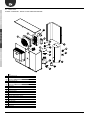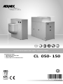
1
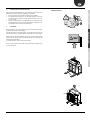
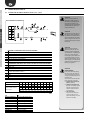
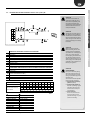
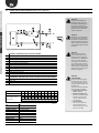
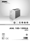
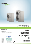
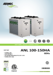
AIR-COOLED REVERSIBLE HEAT PUMP - Installa on manual
REVERSIBLE HEAT PUMPS
• INDOOR UNIT / OUTDOOR UNIT
• HIGH EFFICIENCIES
• PRODUCTION OF HOT WATER UP TO 60 °C
CL 050- 150
ICLIV 12.05 6755562_00
Dear Customer,
Thank you for choosing an AERMEC product. This product is the result of many years of experience and
in-depth engineering research, and it is built using top quality materials and advanced technologies.
In addition, the CE mark guarantees that our appliances fully comply with the requirements of the European
Machinery Directive in terms of safety. We constantly monitor the quality level, and as a result AERMEC products are synonymous with Safety, Quality, and Reliability.
The data may be subject to modifications deemed necessary for improving the product at any time and
without forewarning.
Thank you again.
AERMEC S.p.A
AERMEC S.p.A. reserves the right to make any modifications considered necessary to improve its products at any moment and is not obliged to add these modifications to
machines that have already been manufactured, delivered or are under construction.
Aermec code 12.05 6755562_00
3
AERMEC S.p.A.
37040 Bevilacqua (VR) Italy–Via Roma, 996
Tel. (+39) 0442 633111
Telefax 0442 93730–(+39) 0442 93566
www .aermec. com - info @aermec. com
CL
SERIAL NUMBER
DECLARATION OF CONFORMITY
We, the undersigned, hereby declare under our own responsibility that the assembly in question,
defined as follows:
NAME
CL
TYPE
AIR/WATER REVERSIBLE HEAT PUMP
MODEL
To which this declaration refers, complies with the following harmonised standards:
IEC EN 60335-2-40
Safety standard regarding electrical heat pumps, air conditioners and dehumidifiers.
IEC EN 61000-6-1
IEC EN 61000-6-3
Immunity and electromagnetic emissions for residential environments.
IEC EN 61000-6-2
IEC EN 61000-6-4
Immunity and electromagnetic emissions for industrial environments
EN378
Refrigerating system and heat pumps - Safety and environmental requirements.
UNI EN 12735
UNI EN 14276
Seamless, round copper pipes for air conditioning and refrigeration.
Pressurised equipment for cooling systems and heat pumps.
Thereby, compliant with the essential requirements of the following directives:
- LVD Directive: 2006/95/CE
- Electromagnetic Compatibility Directive 2004/108/CE.
- Machinery Directive 2006/42/CE
- PED Directive regarding pressurised devices 97/23/CE (Form A: CL050-090)
The product, in agreement with Directive 97/23/EC, satisfies the Total quality Guarantee procedure (form H for size 100 - 150) with certificate
no. 06/270-QT3664 Rev. 6 issued by the notified body n.1131 CEC via Pisacane 46 Legnano (MI) - Italy
The person authorised to constitute the technical file is: Massimiliano Sfragara - 37040 Bavilacqua (VR) Italy - Roma, 996
Bevilacqua
23/12/2011
Marketing Manager
Signature
4
Aermec code 12.05 6755562_00
SELECTION AND PLACE OF INSTALLATION ................................................................... 7
3.
4.
4.1.
4.2.
4.3.
POSITIONING .................................................................................................................. 7
MAIN HYDRAULIC CIRCUITS .......................................................................................... 8
INTERNAL AND EXTERNAL HYDRAULIC CIRCUIT TO CL ° / H/ L................................... 8
INTERNAL AND EXTERNAL HYDRAULIC CIRCUIT TO CL P / HP / LP ............................ 9
INTERNAL AND EXTERNAL HYDRAULIC CIRCUIT TO CL A / HA / LA..........................10
5.
EXAMPLE OF CL SYSTEM WITH DHW PRODUCTION WITH VMF DHW
ACCESSORY ...................................................................................................................11
6.
DISCHARGE HOOD POSSIBLE CONFIGURATIONS SITE MODIFIED .........................12
7.
DIMENSIONS .................................................................................................................14
8.
POSITION OF HYDRAULIC CONNECTIONS ..................................................................16
9.
WEIGHT DISTRIBUTION ON SUPPORTS % WEIGHT OF UNITS WHEN EMPTY .....18
10.
10.1.
10.1.1.
10.1.2.
10.1.3.
10.1.4.
10.1.5.
10.1.6.
10.1.7.
10.1.8.
ELECTRIC POWER CONNECTION TO THE ELECTRICAL MAINS ..................................20
ELECTRIC CONNECTIONS .............................................................................................20
UXILIARY CONNECTIONS UNDER THE RESPONSIBILITY OF THE USER/INSTALLER .21
SUMMER/WINTER REMOTE CONTROL C/F ..............................................................21
ON/OFF CONTROL IA ..................................................................................................21
REMOTE ALARM AE ....................................................................................................21
REMOTE PANEL TRA ...................................................................................................21
CONTACT FOR THERMOSTATING DOMESTIC HOT WATER DHW TWS ...................21
CONTACT FOR BOILER CONTROL ...............................................................................21
PR3 CONNECTION ACCESSORY ..................................................................................21
11.
CONTROL AND COMMISSIONING ...............................................................................21
Aermec code 12.05 6755562_00
PREPARATION FOR COMMISSIONING.........................................................................21
SEASON CHANGEOVER .................................................................................................22
SEASON CHANGEOVER ON MACHINE .........................................................................22
ENABLING OF REMOTE PANEL .....................................................................................22
12.
CALIBRATIONS OF SAFETY AND CONTROL PARAMETERS .........................................22
13.
13.1.
13.2.
13.3.
13.4.
13.5.
13.6.
13.7.
OPERATING FEATURES..................................................................................................23
SET POINT IN COOLING MODE ....................................................................................23
SET POINT IN HEATING MODE.....................................................................................23
COMPRESSOR START UP DELAY...................................................................................23
CIRCULATION PUMPS ...................................................................................................23
ANTI FREEZE ALARM ....................................................................................................23
WATER FLOW RATE ALARM ..........................................................................................23
SETTING MAXIMUM VOLTS DCP .................................................................................23
14.
14.1.
14.2.
14.3.
14.4.
ROUTINE MAINTENANCE .............................................................................................24
HYDRAULIC CIRCUIT .....................................................................................................24
ELECTRIC CIRCUIT .........................................................................................................24
COOLING CIRCUIT .........................................................................................................24
MECHANICAL CHECKS ..................................................................................................24
15.
EXTRAORDINARY MAINTENANCE ...............................................................................24
16.
DISPOSAL .......................................................................................................................24
17.
17.1.
17.2.
PROCEDURE FOR SELECTION OF THE TYPE OF SYSTEM ............................................25
HOW TO MODIFY A PARAMETER FROM THE USER MENU........................................25
HOW TO MODIFY A PARAMETER FROM THE INSTALLER MENU...............................25
18.
TROUBLESHOOTING .....................................................................................................26
19.
SPARE PARTS..................................................................................................................27
TECHNICAL SECTION
2.
11.1.
11.2.
11.3.
11.4.
INSTALLER SECTION
GENERAL WARNINGS FOR THE INSTALLER ................................................................... 6
PRESERVATION OF THE DOCUMENTATION .................................................................. 6
WARNINGS REGARDING SAFETY AND INSTALLATION STANDARDS .......................... 6
USER SECTION
1.
1.1.
1.2.
5
TECHNICAL SECTION
INSTALLER SECTION
GENERAL WARNINGS FOR THE INSTALLER
AERMEC CL are constructed according to the acknowledged technical standards and safety regulations.
They have been designed for air conditioning and the
production of domestic hot water (DHW) and must be
used compatibility with their technical features. Any
contractual or extracontractual liability of the Company
is excluded for injury/damage to persons, animals or
objects owing to installation, regulation and maintenance errors or improper use. All uses not expressly
indicated in this manual are prohibited.
ELECTRIC PART
1.
IEC EN 60335 2 40,
2.
IEC EN 61000 6 1/2/3/4
1.
ACOUSTIC PART
1.
ISO DIS 9614/2
intensimetric method
FAN
1.
EUROPEAN RULES N. 327/2011
DIRETTIVA 2009/125/EC
PROTECTION RATING
IP24
USER SECTION
1.
Standards complied with
WHEN DESIGNING and MANUFACTUR
ING the unit:
SAFETY
1.
Machinery Directive
2006/42/CE
2.
Low Voltage Directive
LVD 2006/95/CE
3.
Electromagnetic Compatibility
Directive EMC 2004/108/EC
4.
Directive regarding pressurised
devices
PED 97/23/CE, EN 378,
5.
UNI12735, UNI14276
CERTIFICATION
1.
EUROVENT
REFRIGERANT GAS
This unit contains fluoride gases with
greenhouse effect covered by the Kyoto
Protocol. Maintenance and disposal must
only be performed by qualified staff, in
compliance with standards in force.
1.1.
2.
3.
4.
PRESERVATION OF THE DOCUMENTA
TION
The instructions and all related documentation
must be given to the user of the system, who is
responsible for preserving the same so that they
are always on hand when required.
Read this file carefully; the execution of all jobs
must be performed by qualified staff, according
to the Standards in force on this subject in the
different countries.
The appliance warranty does not cover the
costs for ladders, scaffolding, or other elevation
systems that may become necessary for carrying
out servicing under warranty.
Do not modify or tamper with the appliance as
dangerous situations can be created and the
manufacturer will not be liable for any damage
caused. The warranty shall be become null and
void if the above-mentioned indications are not
respected.
1.2.
1.
2.
WARNINGS REGARDING SAFETY AND
INSTALLATION STANDARDS
The appliance must be installed by a qualified
and suitably trained technician, in compliance
with the national legislation in force in the country of destination.
AERMEC will not assume any liability for damage
if these instructions are not respected.
Before beginning any operation, READ THESE
INSTRUCTIONS CAREFULLY AND CARRY OUT
THE SAFETY CHECKS IN ORDER TO REDUCE ALL
HAZARDS TO MINIMUM. All the staff involved
must have thorough knowledge of the operations and any dangers that may arise at the
moment in which the installation operations are
carried out.
ATTENTION
1.
The refrigerant fluid circuit is pressurised. Interventions must only be
performed on the appliance by ATS
(Authorised Technical Service) or a
qualified technician.
6
2.
GAS R410A
The chiller is delivered with a sufficient amount of R410A refrigerant
fluid for operation. It is a chlorinefree refrigerant fluid that does not
damage the ozone layer. R410A
is not inflammable. However, all
maintenance must be performed
exclusively by a specialised
technician with suitable protective
equipment.
3.
Danger of electric shock!
The appliance must be disconnected from the mains power supply
before the chiller is opened.
Aermec code 12.05 6755562_00
2.
SELECTION AND PLACE OF INSTALLATION
HANDLING EXAMPLE
3.
TECHNICAL SECTION
Before beginning the installa on process, decide with the customer where the appliance is to be installed, whilst paying a en on to the following:
1. the support surface must be capable of suppor ng the unit weight;
2. the safety differences between the unit and other appliances or structures
must be scrupulously respected so that the inlet and outlet air from the fans
is free to circulate;
3. the unit must be installed by an enabled technician in compliance with the
na onal legisla on in force in the country of des na on, respec ng the minimum technical spaces in order to allow maintenance.
POSITIONING
INSTALLER SECTION
Before handling the unit, verify the li ing capacity of the machines used, respecting the indica ons given on the packaging.
To handle the machine on horizontal surfaces, use fork li trucks or similar in the
most appropriate manner, paying a en on to the distribu on of the unit weight.
Posi on the unit in the place indicated by the customer, placing a rubber covering
between the base and the support (min. thickness 10 mm.) or alterna vely an vibra on feet (ACCESSORIES).
For further informa on, refer to the dimensional tables
USER SECTION
Fix the unit checking that it is level. Make sure that the hydraulic and electric part
can be easily reached.
Aermec code 12.05 6755562_00
7
TECHNICAL SECTION
4.
MAIN HYDRAULIC CIRCUITS
4.1.
INTERNAL AND EXTERNAL HYDRAULIC CIRCUIT TO CL ° / H/ L
4
5
4
INSTALLER SECTION
9
3
11
13
6
ATTENTION
The choice and installation of
components outside the unit is
the installer's responsibility, who
must operate according to the
code of practice and in compliance
with the Standard in force in the
country of destination.
7
10
ATTENTION
The hydraulic connection pipes to
the appliance must be suitably dimensioned for the effective water
flow rate requested by the system
when running. The water flow rate
to the heat exchanger must always
be constant.
14
1
8
2
5
USER SECTION
1
2
3
4
5
8
6
12
11
4
STANDARD CL COMPONENTS SUPPLIED AS PER STANDARD
Plate exchanger
Water filter
Flow switch
Air vent valve
Water temperature probes (IN/OUT)
Safety valve (not available for the sizes 100-150)
RECOMMENDED COMPONENTS NOT SUPPLIED FOR WHICH INSTALLER IS RESPONSIBLE
6 Anti-vibration joints
7 Cut-off cocks
9 Expansion vessel
System storage tank (installation recommended whenever the system water content is
10
less than that indicated in TAB. 1)
11 Manometer
12 Pump
13 Resistance
14 Drain cock
MINIMUM WATER CONTENT
Number of compressors
Recommended minimum
water content
025 030 040 050 070 080 090 100 150 200
1
1
1
1
1
1
1
1
1
1
Model "°" - "L"
l/kW 4
4
4
4
4
4
4
4
4
4
Model "H"
l/kW 10
10
10
10
10
10
10
10
10
10
n°
TAB. 1
PH
Electric conductivity
Chloride ions
Sulphuric acid ions
Total iron
Alkalinity M
Total hardness
Sulphur ions
Ammonia ions
Silicone ions
8
6-8
Less than 200 mV/cm (25°C)
Less than 50 ppm
Less than 50 ppm
Less than 0.3 ppm
Less than 50 ppm
Less than 50 ppm
None
None
Less than 30 ppm
ATTENTION
Wash the system thoroughly
before connecting the unit. This
cleaning operation will eliminate
any residues such as welding drips,
scale, rust, or other impurities
from the piping. These substances
can also deposit inside and cause
appliance malfunctioning. The connection piping must be adequately
supported so that its weight is not
borne by the appliance.
ATTENTION
SYSTEM DRAINING
If the system should stop during
the winter period, the water present in the exchanger may freeze,
causing irreparable damage to the
exchanger itself.
There are three solutions possible
for the prevention of freezing:
1. Drain the water from the appliance completely.
2. Operation with glycoled water, with a percentage of glycol
selected on the basis of the
minimum external temperature envisioned.
3. Use of resistances.
In this case, the resistances
must be live for the entire
period that freezing may occur
(machine in stand-by).
Aermec code 12.05 6755562_00
ATTENTION
The choice and installation of
components outside the unit is
the installer's responsibility, who
must operate according to the
code of practice and in compliance
with the Standard in force in the
country of destination.
4
9
4
11
13
3
6
7
10
ATTENTION
The hydraulic connection pipes to
the appliance must be suitably dimensioned for the effective water
flow rate requested by the system
when running. The water flow rate
to the heat exchanger must always
be constant.
14
1
8
12
2
5
1
2
3
4
5
8
9
12
6
11
4
ATTENTION
Wash the system thoroughly
before connecting the unit. This
cleaning operation will eliminate
any residues such as welding drips,
scale, rust, or other impurities
from the piping. These substances
can also deposit inside and cause
appliance malfunctioning. The connection piping must be adequately
supported so that its weight is not
borne by the appliance.
STANDARD CL COMPONENTS SUPPLIED AS PER STANDARD
Plate exchanger
Water filter
Flow switch
Air vent valve
Water temperature probes (IN/OUT)
Safety valve (not available for the sizes 100-150)
Expansion vessel
Pump
RECOMMENDED COMPONENTS NOT SUPPLIED FOR WHICH INSTALLER IS RESPONSIBLE
6 Anti-vibration joints
7 Cut-off cocks
System storage tank (installation recommended whenever the system water content is
10
less than that indicated in TAB.1)
11 Manometer
13 Resistance
14 Drain cock
MINIMUM WATER CONTENT
Number of compressors
Recommended minimum
water content
PH
Electric conductivity
Chloride ions
Sulphuric acid ions
Total iron
Alkalinity M
Total hardness
Sulphur ions
Ammonia ions
Silicone ions
025 030 040 050 070 080 090 100 150 200
1
1
1
1
1
1
1
1
1
1
Model "°" - "L"
l/kW 4
4
4
4
4
4
4
4
4
4
Model "H"
l/kW 10
10
10
10
10
10
10
10
10
10
n°
6-8
Less than 200 mV/cm (25°C)
Less than 50 ppm
Less than 50 ppm
Less than 0.3 ppm
Less than 50 ppm
Less than 50 ppm
None
None
Less than 30 ppm
Aermec code 12.05 6755562_00
INSTALLER SECTION
5
TECHNICAL SECTION
INTERNAL AND EXTERNAL HYDRAULIC CIRCUIT TO CL P / HP / LP
TAB. 1
USER SECTION
4.2.
ATTENTION
SYSTEM DRAINING
If the system should stop during
the winter period, the water present in the exchanger may freeze,
causing irreparable damage to the
exchanger itself.
There are three solutions possible
for the prevention of freezing:
1. Drain the water from the appliance completely.
2. Operation with glycoled water, with a percentage of glycol
selected on the basis of the
minimum external temperature envisioned.
3. Use of resistances.
In this case, the resistances
must be live for the entire
period that freezing may occur
(machine in stand-by).
9
INTERNAL AND EXTERNAL HYDRAULIC CIRCUIT TO CL A / HA / LA
TECHNICAL SECTION
4.3.
ATTENTION
The choice and installation of
components outside the unit is
the installer's responsibility, who
must operate according to the
code of practice and in compliance
with the Standard in force in the
country of destination.
4
11
9
4
5
13
FL
6
10
USER SECTION
INSTALLER SECTION
3
7
ATTENTION
The hydraulic connection pipes to
the appliance must be suitably dimensioned for the effective water
flow rate requested by the system
when running. The water flow rate
to the heat exchanger must always
be constant.
14
1
8
12
5
1
2
3
4
5
8
9
10
12
13
14
2
6
4
11
ATTENTION
Wash the system thoroughly
before connecting the unit. This
cleaning operation will eliminate
any residues such as welding drips,
scale, rust, or other impurities
from the piping. These substances
can also deposit inside and cause
appliance malfunctioning. The connection piping must be adequately
supported so that its weight is not
borne by the appliance.
STANDARD CL COMPONENTS SUPPLIED AS PER STANDARD
Plate exchanger
Water filter
Flow switch
Air vent valve
Water temperature probes (IN/OUT)
Safety valve
Expansion vessel
System storage tank
Pump
200 W resistance antifreeze
Drain cock
RECOMMENDED COMPONENTS NOT SUPPLIED FOR WHICH INSTALLER IS RESPONSIBLE
6 Anti-vibration joints
7 Cut-off cocks
11 Manometer
MINIMUM WATER CONTENT
Number of compressors
Recommended minimum
water content
PH
Electric conductivity
Chloride ions
Sulphuric acid ions
Total iron
Alkalinity M
Total hardness
Sulphur ions
Ammonia ions
Silicone ions
10
025 030 040 050 070 080 090 100 150 200
1
1
1
1
1
1
1
1
1
1
Model "°" - "L"
l/kW 4
4
4
4
4
4
4
4
4
4
Model "H"
l/kW 10
10
10
10
10
10
10
10
10
10
n°
6-8
Less than 200 mV/cm (25°C)
Less than 50 ppm
Less than 50 ppm
Less than 0.3 ppm
Less than 50 ppm
Less than 50 ppm
None
None
Less than 30 ppm
TAB. 1
ATTENTION
SYSTEM DRAINING
If the system should stop during
the winter period, the water present in the exchanger may freeze,
causing irreparable damage to the
exchanger itself.
There are three solutions possible
for the prevention of freezing:
1. Drain the water from the appliance completely.
2. Operation with glycoled water, with a percentage of glycol
selected on the basis of the
minimum external temperature envisioned.
3. Use of resistances.
In this case, the resistances
must be live for the entire
period that freezing may occur
(machine in stand-by).
Aermec code 12.05 6755562_00
EXAMPLE OF CL SYSTEM WITH DHW PRODUCTION with VMF-DHW ACCESSORY
2
TECHNICAL SECTION
5.
1
INSTALLER SECTION
M
3
8
5
6
7
USER SECTION
4
CL
VMF SYSTEM FOR THE PRODUCTION AND MANAGEMENT OF THE HOT WATER AND DHW (accessory)
1 E5 (black and white)
VMF-ACS3KTN | 6KTN |8KTN
2 - 3-way valve (not supplied)
- DHW temperature probe (supplied)
- Resistance for DHW storage tank (anti-legionella cycle management)
3 3-way valve (not supplied)
4 Electrical resistance for DHW storage tank (not supplied) (anti-legionella cycle management)
5 RS-485 MOD-BUS interface (MODU-485A ACCESSORY)
6 DHW storage tank (not supplied)
7 Electrical resistance (BSKW ACCESSORY)
8 System storage tank (not supplied)
9 For further information regarding the VMF
system, refer to the documentation available
on the website: www .aermec. com
10 The accessory is necessary for the VMF
system to communicate wit the heat pump.
Aermec code 12.05 6755562_00
11
TECHNICAL SECTION
6.
DISCHARGE HOOD POSSIBLE CONFIGURATIONS SITE MODIFIED
CL 050 - 070 - 080 - 090
1
3
2
INSTALLER SECTION
Default posi on
4
5
6
USER SECTION
CL 100 - 150
1
2
3
4
5
Default posi on
CL 100 - 150
1
2
3
5
Default posi on
12
Aermec code 12.05 6755562_00
INSTALLER SECTION
TECHNICAL SECTION
DUCTING EXAMPLE
USER SECTION
CLPA SUCTION PLENUM:
ATTENTION
Do not allow the weight of the ductwork to
be imposed on the plas c discharge hood
Aermec code 12.05 6755562_00
13
DIMENSIONS
1020
1281
CL 050 090
VERSION: STANDARD"°"
VERSION: WITH PUMP "P"
26
1160
INSTALLER SECTION
TECHNICAL SECTION
7.
450
322
213
USER SECTION
798
97
34
400
630
571
125
25
1000 mm
24
410
300 mm
14
800 mm
41
991
127
1000 mm
500 mm
Aermec code 12.05 6755562_00
USER SECTION
INSTALLER SECTION
TECHNICAL SECTION
CL 050 090
VERSION: WITH STORAGE TANK AND PUMP "A "
1000 mm
300 mm
1000 mm
800 mm
500 mm
Aermec code 12.05 6755562_00
15
1674
TECHNICAL SECTION
CL 100 150
VERSION: STANDARD"°"
VERSION: WITH "P"
VERSION: WITH STORAGE TANK AND PUMP "A "
801
USER SECTION
INSTALLER SECTION
1895
321
1326
227
49
48
30
47
184
80
393
1111
392
23
758
23
1000 mm
16
800 mm
50
1774
50
800 mm
800 mm
800 mm
Aermec code 12.05 6755562_00
8.
POSITION OF HYDRAULIC CONNECTIONS
TECHNICAL SECTION
CL 050 090
VERSION: STANDARD"°"
VERSION: WITH PUMP "P"
69
INSTALLER SECTION
189
48
52
52
USER SECTION
180
111
180
69
189
111
48
CL 050 090
VERSION: WITH STORAGE TANK AND PUMP "A"
OUT 1”1/4
IN 1”1/4
Aermec code 12.05 6755562_00
17
TECHNICAL SECTION
CL 100 150
VERSION: STANDARD"°"
VERSION: WITH PUMP "P"
VERSION: WITH SOTRAGE TANK AND PUMP "A"
102
415
INSTALLER SECTION
122
USER SECTION
123
2
18
797
801
2
Aermec code 12.05 6755562_00
4 SUPPORTS
6 SUPPORTS
Yg
Yg
C
A
C
A
E
G
G
B
B
D
BARYCENTRE
Gx
Gy
A
VERSION STANDARD "°"
171
487
35.8%
21.9%
26.3%
16.0%
172
486
35.7%
22.0%
26.1%
16.1%
173
462
458
483
887
879
35.7%
22.2%
22.6%
22.3%
30.4%
30.3%
25.9%
20.0%
20.1%
MODEL COOLING ONLY "°" AND SILENCED MODE "L"
050
°P
217
070
°P
225
080
090
°P
221
100
°P
482
VERSION WITH PUMP "P"
171
474
36.4%
22.4%
176
469
36.0%
173
454
470
906
36.3%
22.3%
452
903
22.5%
150
VERSION
°P
487
F
D
WEIGHT
UNIT
MODEL COOLING ONLY "°" AND SILENCED MODE "L"
050
°
208
070
°
210
080
090
°
212
100
°
469
150
°
471
CL
INSTALLER SECTION
Xg
Xg
INSTALLER SECTION
TECHNICAL SECTION
WEIGHT DISTRIBUTION ON SUPPORTS % WEIGHT OF UNITS WHEN EMPTY
WEIGHT DISTRIBUTION ON SUPPORTS (%)
B
C
D
E
F
KIT
VT
-
-
-
-
-
-
16.1%
27.4%
26.9%
-
-
-
25.5%
15.7%
-
-
-
23.2%
24.8%
16.0%
-
-
-
22.8%
29.3%
25.1%
20.9%
15.8%
27.5%
-
-
-
29.2%
21.0%
27.3%
-
-
-
USER SECTION
9.
MODEL COOLING ONLY "°" AND SILENCED MODE "L" VERSIONE WITH STORAGE TANK AND PUMP"A"
050
070
080
090
100
150
°A
252
196
816
7.7%
5.9%
20.3%
15.7%
28.4%
22.0%
-
°A
260
201
816
7.1%
5.7%
20.7%
16.7%
27.6%
22.2%
-
°A
°A
°A
256
532
537
198
447
446
815
925
929
7.4%
22.3%
22.3%
5.8%
28.2%
28.0%
20.6%
21.9%
22.0%
16.2%
27.6%
27.7%
28.0%
-
22.0%
-
-
Aermec code 12.05 6755562_00
19
WEIGHT
BARYCENTRE
UNIT
Gx
Gy
MODEL HEATING PUMP "H" VERSION STANDARD "°"
050
H
229
180
496
070
H
240
179
479
080
090
H
234
180
489
100
H
504
457
885
150
H
527
448
845
VERSION
MODEL HEATING PUMP "H" VERSION WITH PUMP "P"
050
HP
239
181
070
HP
250
180
080
090
HP
243
180
100
HP
517
450
150
HP
543
443
A
WEIGHT DISTRIBUTION ON SUPPORTS (%)
B
C
D
E
F
KIT
VT
34.1%
22.8%
25.8%
17.3%
-
-
-
35.1%
23.2%
25.1%
16.6%
-
-
-
34.5%
22.6%
24.1%
23.0%
30.1%
30.7%
25.5%
20.3%
19.9%
17.0%
27.0%
25.3%
-
-
-
483
34.7%
23.3%
25.2%
16.9%
-
-
-
468
35.6%
23.7%
24.4%
16.2%
-
-
-
477
902
868
35.1%
22.6%
23.9%
23.4%
29.1%
29.7%
24.9%
21.1%
20.7%
16.6%
27.1%
25.7%
-
-
-
6.9%
5.7%
19.2%
15.9%
28.6%
23.7%
-
6.6%
5.4%
20.6%
16.9%
27.7%
22.8%
-
6.7%
22.6%
23.3%
5.6%
28.1%
28.6%
19.8%
22.0%
21.6%
16.3%
27.3%
26.5%
28.2%
-
23.3%
-
-
MODEL HEATING PUMP "H" VERSION WITH STORAGE TANK AND PUMP"A"
050
HA
274
204
833
070
HA
284
203
825
080
090
HA
279
204
830
100
HA
567
443
921
150
HA
593
441
899
USER SECTION
INSTALLER SECTION
TECHNICAL SECTION
CL
20
Aermec code 12.05 6755562_00
ELECTRIC POWER CONNECTION TO
THE ELECTRICAL MAINS
The CL heat pumps are completely wired at the factory
and only require connec on to the electrical mains,
downstream from a unit switch, according to that
envisioned by the Standards in force on this subject in
the country of installation.
It is also advised to check that:
the electrical mains features are suitable for the absorption values indicated in the electrical data table.
The unit must only be powered when installation has
been completed (hydraulic and electric).
Respect the connection indications of the phase and
earth wires.
The power supply line must have a relevant protection
against short circuits mounted upstream and dispersions to earth, which isolate the system with respect to
other utilities.
The voltage must be within a tolerance of ±10% of
the nominal power supply voltage of the machine
(for unbalanced three-phase unit max 3% between
the phases). Whenever these parameters are not respected, contact the electric energy public body.
For electric connections, use the cables with double
isolation according to the Standards in force on this
subject in the different countries.
TECHNICAL SECTION
All the electrical opera ons must be carried out bySTAFF IN POSSESSION OF THE NECES
SARY QUALIFICATIONS BY LAW, suitably trained and informed on the risks related to these
opera ons.
The features of the electrical lines and of the related components must be determined by STAFF
QUALIFIED TO DESIGN ELECTRICAL SYSTEMS, in compliance with the interna onal and na onal
regula ons of the place of installa on of the unit and in compliance with the regula ons in force at
the me of installa on.
For the installa on requirements refer only to the wiring diagram supplied with the appliance. The
wiring diagram along with the manuals must be kept in good condi on and ALWAYS BE AVAILABLE
FOR ANY FUTURE INTERVENTIONS ON THE UNIT.
ded for maximum lengths of 50 m.
For longer lengths or different cable laying, it is up to
the DESIGN ENGINEER to dimension the appropriate line switch, the power supply line as well as the
connection to the earth wire and connection cables
depending on:
the length;
the type of cable;
the absorption of the unit and the physical location
and also the environment temperature.
THE FOLLOWING ARE MANDATORY
The use of an omnipolar magnet circuit breaker switch
is mandatory, in compliance with the IEC-EN Standards
(contact opening at least 3 mm), with suitable cut-off
power and differential protection on the basis of the
electric data table shown below, installed as near as
possible to the appliance.
It is mandatory to make an effective earth connection. The manufacturer is not liable for any damage
caused by the lack of or ineffective appliance earth
connection.
For units with three-phase power supply, check the
correct connection of the phases.
ATTENTION
It is prohibited to use the water
pipes to earth the appliance.
ATTENTION
Check the tightness of all power
wire clamps on commissioning
and after 30 days from start-up.
Successively check them every six
months.
Loose terminals can cause
overheating of the cables and
components.
10.1. ELECTRIC CONNECTIONS
Before connecting the unit to the power supply mains,
make sure that the isolating switch is open.
Open the front panel
Use the holes in the lower part of the framework for
the main electric power supply cable and the cables of
the other external connections under the responsibility
of the installer.
It is prohibited to access positions not specifically
envisioned in this manual with electric cables.
Avoid direct contact with non-insulated copper piping
and with the compressor.
Identify the clamps for the electric connection and
always refer exclusively to the wiring diagram supplied
The cable sections shown in the table are recommen-
INSTALLER SECTION
It is mandatory to verify that the machine is water ght before making the electrical connec ons and it
must only be powered a er the hydraulic and electrical works have been completed.
USER SECTION
10.
ATTENTION
FOR THE MODEL 230V/1/50Hz:
The unit is equipped with a compressor
starting device for the reduction of the
starting current. This device contains
capacitors that could overheat in case
of close repeated starts. In case power
supply to the unit is removed, wait
at least 3 minutes before restoring it
again.
°/L
H
Fans [n°]
H
°/L
H
090 ° / L / H
°/L
100
H
080
150
Power supply
°/L
Compressors [n°]
070
°/L
H
400V/3N/50Hz
050
Vers
Size
ELECTRIC DATA TABLE*
1
1
1
1
1
1
1
1
2
2
2
2
TOTAL ABSORPTION
L.R.A.: F.L.A.:
[A]
[A]
77,2
64,2
13,7
13,5
77,2
15,4
74,2
77,2
94,2
105,2
90,9
77,7
14,7
17,0
15,2
20,4
27,4
27,0
92,6
30,8
109,3
30,3
RECOMMENDED CABLE SECTION x 50 mt. max. length
SEC. A
SEC. B EARTH (PE)
cables for
phases
Cable section Total cables
[mm2]
single phase
[mm2]
[n°]
[n°]
[mm2]
[n°]
IL
[A]
3+N
4
4 mm²
4
1,5 mm²
4 mm²
16
3+N
4
4 mm²
4
1,5 mm²
4 mm²
25
3+N
4
6 mm²
4
1,5 mm²
6 mm²
25
3+N
4
6 mm²
4
1,5 mm²
6 mm²
25
3+N
4
10 mm²
4
1,5 mm²
10 mm²
40
3+N
4
16 mm²
4
1,5 mm²
16 mm²
40
Maximum input power
Maximum input current
Peak current
Power supply
Aermec code 12.05 6755562_00
PE
phase phase phase neutral
230/1/50Hz
PE
*Data refer to th version "°" standard, without pump
KEY
F.L.I.:
F.L.A.:
L.R.A.:
Sec A:
400V/3N/50Hz
3+N:
Sec B:
EARTH:
IL:
phase phase phase neutral
3 phases + neutral
Controls and safety device connection
Earth wire to connect to unit
Master switch
21
TECHNICAL SECTION
INSTALLER SECTION
with the unit.
For the operational connection of the unit, take the
power supply cable to the electric control board inside
the unit and connect it to the U-N and PE clamps, respecting (U) phase, (N) neutral, (PE) earth in the event
of single-phase power supply (230V/50Hz),
U-V-W as phases N as neutral and PE as earth in the
event of three-phase power supply (400V/3N/50Hz).
Re-position the inspection panels.
Ensure that all protections removed for the electric
connection have been restored before powering the
unit electrically.
Position the system master switch (outside the appliance) at “ON”.
10.1.1. UXILIARY CONNECTIONS UNDER THE RE
SPONSIBILITY OF THE USER/INSTALLER
All clamps to which reference is made in the following
explanations are part of the 13 POLE removable terminal board situated inside the electric control board and
connected to the MODUCONTROL.
10.1.2. SUMMER/WINTER REMOTE
CONTROL C/F
To prepare a remote summer/winter switch-over
device, connect the device contact to clamps 3 and 5 of
the 13 POLE terminal board.
Please note that, on request by the Aermec customer
or the legitimate owner of the machine, the units in
this series can be started up by the Aermec After-Sales
Service in your area (valid only on ITALIAN territory).
The start of operation must be scheduled in advance
agreed on the basis of the time frame regarding the
realisation of the system. Prior to the intervention,
all other works (electrical and hydraulic connections,
priming and bleeding of air from the system) must
have been completed.
commissioning
Preliminary operations to be performed with no
voltage present
Control:
All safety conditions have been respected.
The unit is correctly fixed to the support surface.
The minimum technical spaces have been respected.
That the main power supply cables have appropriate
cross-sec on, which can support the total absorp on
of the unit. (see electric data sec ons) and that the
unit has been duly connected to earth.
That all the electrical connec ons have been made
correctly and all the clamps adequately ghtened.
evaporator inlet. (Mandatory component for warranty
to be valid).
Make sure that the circulation pump/s is/are operating
and that the water flow rate is sufficient to close the
flow switch contact.
Check the water flow rate, measuring the pressure
difference between evaporator inlet and outlet and
calculate the flow rate using the evaporator pressure
drop diagram present in this documentation.
Check correct operation of the flow switches, if installed; on closing the cut-off valve at the heat exchanger
outlet, the unit must display the block. Finally, open
the valve and rearm the block.
Machine COMMISSIONING
The unit can be used after all of the above-mentioned
controls have been performed.
Close the electric control board hatch.
Position the appliance master switch at ON.
Press the ON key for 3 sec to switch the machine on.
By pressing the ON key , the display will show the
temperature of the water and the type of machine
operation. Check the operating parameters set (setpoint) and reset any alarms present. The unit will begin
operating after a few minutes.
USER SECTION
With the machine on, check
10.1.3. ON/OFF CONTROL IA
To prepare a remote ON/OFF switch-over device,
connect the device contact to clamps 4 and 5 of the 13
POLE terminal board.
10.1.4. REMOTE ALARM AE
If it should be necessary to display the machine block
in a remote point due to operating anomaly, clamps
6 and 7 of the 13 POLE terminal board can be used to
connect a visual or acoustic alarm signal.
10.1.5. REMOTE PANEL TRA
To prepare a remote ON/OFF switch-over device,
connect the device contact to clamps 8 and 9 of the 13
POLE terminal board.
10.1.6. CONTACT FOR THERMOSTATING DOME
STIC HOT WATER DHW TWS
To prepare a stand-alone thermostating device, connect to clamps 10 and 11 of the 13 POLE terminal
board.
10.1.7. CONTACT FOR BOILER CONTROL
To prepare a boiler control, connect to clamps 12 and
13 of the 13 POLE terminal board.
10.1.8. PR3 CONNECTION ACCESSORY
If you should have the PR3 accessory, always connect
it to the 13 POLE terminal board as shown in the wiring diagram. Remember that the maximum distance
accepted is 150 mt. REMEMBER THAT THE PR3 AS
WELL AS BEING CONNECTED MUST BE ENABLED (see
subsequent pages).
11.
CONTROL AND
COMMISSIONING
11.1. PREPARATION FOR COMMISSIONING
22
ATTENTION
FOR THE MODEL 230V/1/50Hz:
The unit is equipped with a compressor starting device for the reduction
of the starting current. This device
contains capacitors that could
overheat in case of close repeated
starts. In case power supply to the
unit is removed, wait at least 3 minutes before restoring it again.
The following operations are to be carried out when
the unit is live.
Supply power to the unit by turning the master switch
to the ON position. The display will switch on a few
seconds after voltage has been supplied; check that
the operating status is on OFF.(OFF BY KEY B on lower
side of the display).
Use a tester to verify that the value of the power
supply voltage to the U.V.W. phases is equal to 400V
±10%; also verify that the unbalance between phases
is no greater than 3%.
Check that the connections made by the installer are in
compliance with the documentation.
Verify that the compressor sump resistance/s is/are
operating by measuring the increase in temperature of
the oil pan. The resistance/s must function for at least
12 hours before start-up of the compressor and in any
event, the temperature of the oil pan must be 10-15°C
higher than room temperature.
HYDRAULIC CIRCUIT
Check that all hydraulic connections are made
correctly, that the plate indications are complied with
and that a mechanical filter has been installed at the
COOLING CIRCUIT
CHECK:
That the compressor input current is lower
than the maximum indicated in the technical data
table.
That in models with three-phase power
supply, the compressor noise level is not abnormal,
symptom of inverse rotation. If this is the case, invert a
phase.
That the voltage value lies within the
pre-fixed limits and that unbalance between the three
phases (three-phase power supply) is not above 3%.
The presence of any refrigerant GAS
leaks, par cularly in correspondence with the manometers pressure transducers and pressure switches
pressure points. (vibra ons during transporta on
could loosen the fi ngs).
Overheating
Comparing the temperature read using a
contact thermostat positioned on the compressor intake with the temperature shown on the low pressure
manometer (saturation temperature corresponding
to the evaporation pressure). The difference between
these two temperatures gives the overheating value.
Optimal values are between 4 and 8°C.
Pressing line temperature. If the
subcooling and overheating values are regular, the
temperature measured in the pressing line pipe at the
outlet of the compressor must be 30/40°C above the
condensation temperature.
Control and safety devices
CHECK:
-
The manual reset high pressure switch.
That stops the compressor, generating the
respective alarm, when the flow pressure exceeds the
set-point value. Its correct operation can be controlled
Aermec code 12.05 6755562_00
11.4. ENABLING OF REMOTE PANEL
Access the INSTALLER SET list using the .key, enter the
password for access to the menu:
installer password 030.
Use the arrow keys to display the PAN parameter
index 9 of the menu, select it using the..key, set it using
the arrow keys on the desired value:
VALUE 1:
SEASON CHANGE piloted by the appliance.
ON/OFF CONTROL from PR3
VALUE 2:
SEASON CHANGE piloted from PR3
ON/OFF CONTROL from the appliance
VALUE 3:
SEASON CHANGE piloted from PR3
ON/OFF CONTROL piloted from PR3
-
The anti-freeze control
The anti-freeze control managed by
electronic regulation and by the temperature probe located at the evaporator outlet is to prevent the formation of ice when the water flow rate is too low. Correct
operation can be checked by progressively increasingly
the anti-freeze set-point until it exceeds the outlet
water temperature and keeping the water temperature
controlled with a high precision thermometer. Verify
that the unit is off and generates the respective alarm
After this operation, take the anti-freeze set-point back
to its original value.
11.2. SEASON CHANGEOVER
11.3. SEASON CHANGEOVER ON MACHINE
Confirm the selection using the
menu using the key.
Access the SET USER list using the key and conform
the password 000 using the same key.
Use the arrow keys to display the STA parameter 0
index of the menu, select it using the key and set it
using the arrow keys on the desired value, VALUE
0 operating in cooling mode VALUE 1 operating in
heating mode.
Confirm the selection using the key and exit the
090
100
150
AP
TAP
TBP
H
°/L
H
°/L
H
°/L
H
°/L
H
Power supply
Fans [n°]
080
°/L
Compressors [n°]
070
°/L
H
400V/3N/50Hz
050
key and exit the
Once the PR3 remote panel is enabled, just operate
directly on the switch to change the season (fig.1). The
machine will switch off automatically and switch back
on with the operating mode selected.
(fig.1)
For further information refer to the USER MANUAL
CALIBRATIONS OF SAFETY AND CONTROL PARAMETERS
Vers
Size
12.
TECHNICAL SECTION
If in possession of the PR3, it must be enabled after
electric connection.
ATTENTION
Commissioning must be performed
with standard settings. Only when
the inspection has been completed
can the operating Set-Point values
be changed.
Before start-up, power the unit
for at least 12 hours, positioning
the magnet circuit breaker switch
and the door lock isolating switch
at ON
INSTALLER SECTION
menu using the key.
Season changeover from PR3
(accessory)
USER SECTION
by closing the air intake to the exchanger (in cooling
mode) and keeping the high pressure manometer under control, check the intervention in correspondence
of the calibration value. Attention: if there is no intervention at the calibration value, stop the compressor
immediately and check the cause. Reset is manual and
can only take place when the pressure drops below the
differential value. (For the set and differential values,
consult the technical manual).
1
1
1
1
1
1
1
1
2
2
2
2
"Taratura magnetotermici
compressori"
"Taratura magnetotermici
ventilatori"
AP
TAP
TBP
(A)
(A)
(bar)
(bar)
(bar)
10,0
9,5
Fisso 6
42
39
40
4
2
Fisso 6
42
39
4
Fisso 6
42
Fisso 6
42
Fisso 10
42
40
39
40
39
40
39
40
2
4
2
4
2
4
2
Fisso 10
42
39
4
40
2
12,5
10,5
15,0
11,0
16,0
16,0
10,0
9,5
12,5
11,0
MANUAL RESET HIGH PRESSURE SWITCH
HIGH PRESSURE TRANSDUCER
LOW PRESSURE TRANSDUCER
Aermec code 12.05 6755562_00
23
TECHNICAL SECTION
13.
OPERATING FEATURES
13.5. ANTI FREEZE ALARM
(Factory set) = 7°C, ∆t = 5°C.
The alarm is always ac ve even in stand-by mode. In
order to prevent damage to the plate heat exchanger
due to the water it contains freezing, on reaching a water temperature value below the minimum an -freeze
set of 3°C, the unit will be switched off immediately
and the rela ve alarm is given. The unit can only
re-start a er manual reset and the an -freeze probe
measures a water temperature over 4°C
. With the unit off and with water temperature below
4°C, the heat exchanger an -freeze electric resistance,
mounted as per standard, is ac vated. It is switched off
when the water temperature exceeds 5°C. The water
pump is always ac ve.
13.2. SET POINT IN HEATING MODE
(Factory set) = 45°C, ∆t = 5°C.
If the unit power supply is restored a er a temporary
interrup on, the mode set will be kept in the memory.
INSTALLER SECTION
13.3. COMPRESSOR
START UP DELAY
USER SECTION
ATTENTION
13.1. SET POINT IN COOLING MODE
Two func ons have been set-up to prevent compressor
start-ups that are too close.
- Minimum time from last switch-off 60 seconds in
cooling mode.
- Minimum time from last switch-on 300 seconds in
heating mode.
13.6. WATER FLOW RATE ALARM
The unit manages a water flow rate alarm controlled
by a differen al pressure switch or flow switch,
installed as per standard on the machine. This type of
safety device can intervene a er the first 30 seconds of
pump opera on, if the water flow rate is not sufficient.
The interven on of this alarm determines compressor
and pump block
13.4. CIRCULATION PUMPS
The circuit board envisions outputs for the management of the circula on pumps.
The u li es side pump starts immediately and a er
the first 30 seconds of opera ng, when the water flow
rate has gone into normal working condi ons, the differen al pressure switch/flow switch control func ons
are ac vated.
Whenever alarms do not occur, the appliance starts.
Anti-freeze set temperature
can only be varied by an
authorised after-sales centre
and only after having checked
that there is a suitable %
anti-freeze solution in the
hydraulic circuit.
Whenever this alarm intervenes, call an authorised
after-sales service immediately.
ATTENTION
FOR THE MODEL 230V/1/50Hz:
The unit is equipped with a compressor starting device for the reduction
of the starting current. This device
contains capacitors that could
overheat in case of close repeated
starts. In case power supply to the
unit is removed, wait at least 3 minutes before restoring it again.
13.7. SETTING MAXIMUM VOLTS DCP
SET DEFAULT VOLT MAX DCP
Max volt DCP (psw 84; param 4)
Available nominal sta c pressure
24
U.M.
(V)
Vers.
CL 050
CL 070
CL 080
CL 090
CL 100
CL 150
°/H
5,0
5,0
5,0
5,5
4,5
5,4
L
°/H/L
3,5
80
3,5
80
3,5
80
4,0
80
3,0
80
4,0
100
Aermec code 12.05 6755562_00
14.4. MECHANICAL CHECKS
ATTENTION
In the 230V/1/50Hz versions with
soft-start, in the event of a power
cut due to technical problems or for
maintenance, in order to preserve
good operation of the appliance
it is mandatory to wait 5 minutes
before re-applying voltage to the
heat pump.
All cleaning is prohibited until the unit has been disconnected from the electric power supply mains 1.
Make sure there is no voltage present before operating.
Periodic maintenance is fundamental to keep the unit
perfectly efficient under an operational and energy
point of view.
It is therefore essential to carry out periodic yearly
controls on the:
CHECK:
1.
The tightening of the screws, the compressors
and the electrical box, as well as the exterior
panelling of the unit. Bad fixing can cause abnormal noises and vibrations.
2.
The state of the structure and the integrity of the
discharge air hood in plastic
If there are any oxidised parts, treat with paint
suitable to eliminate or reduce oxidation.
ATTENTION
In the cooling circuit it is prohibited
to use oxygen or acetylene or other
inflammable or poisonous gases
because they are a cause of explosions or intoxication. We recommend
to envision a machine book (not
supplied, but the user's responsibility), which allows to keep track of the
interventions performed on the unit.
In this way it will be easy to suitably
organise the interventions making
research and the prevention of any
machine breakdowns easier.
Use the date to record date, type
of intervention made (routine
maintenance, inspection or repairs),
description of the intervention,
measures actuated…
14.1. HYDRAULIC CIRCUIT
15.
CHECK:
1.
Water circuit filling.
2.
Water filter cleaning.
3.
Pressure switch or flow switch control.
4.
The absence of air in the circuit (bleeding).
5.
That the water flow rate to the evaporator is
constant.
6.
The thermal insulation of the hydraulic piping.
7.
The percentage of glycol, when envisioned.
the CL are filled with R410A gas and are inspected
at the factory. Under normal conditions they do not
require Technical Assistance related to control of refrigerant gas. Through time gas leakage may be generated,
causing refrigerant to escape and discharge the circuit,
causing appliance malfunctioning. In these cases the
refrigerant leakage points must be detected, repaired
and the refrigerant load is to be replenished, respecting Law n°549 law dated 28 December 1993.
14.2. ELECTRIC CIRCUIT
16.
CHECK:
8.
Safety device efficiency.
9.
The electric power supply voltage.
10. Electrical absorption.
11. Connections tightness.
12. The operation of the compressor guard resistance.
Envisions that disposal of the unit is carried out in
conformity with the Standards in force in the different
countries
ATTENTION
FOR THE MODEL 230V/1/50Hz:
The unit is equipped with a compressor starting device for the reduction
of the starting current. This device
contains capacitors that could
overheat in case of close repeated
starts. In case power supply to the
unit is removed, wait at least 3 minutes before restoring it again.
Aermec code 12.05 6755562_00
EXTRAORDINARY MAINTENANCE
DISPOSAL
USER SECTION
ATTENTION
It is forbidden to LOAD the cooling
circuit with a refrigerant different
to that indicated. Using a different
refrigerant gas can cause serious
damage to the unit.
TECHNICAL SECTION
ROUTINE MAINTENANCE
INSTALLER SECTION
14.
14.3. COOLING CIRCUIT
CHECK:
13. State of compressor.
14. Plate exchanger resistance efficiency.
15. Work pressure.
16. Leak test for water tightness control of the cooling circuit.
17. Operation of high and low pressure switches.
18. Carry out the appropriate checks on the filter
dryer to check efficiency.
25
USER SECTION
INSTALLER SECTION
TECHNICAL SECTION
17.
PROCEDURE FOR SELECTION OF THE TYPE OF SYSTEM
Some parameters in the MODUCONTROL board must
be set appropriately on the basis of the type of system
in which the unit is installed.
These modifications, performed by the installer, are
summarised and organised in the following guided
procedures, with which to correctly set the unit circuit
board parameters.
QUESTION
(1) What type of system terminals
are used in the heating circuit?
(4) Is a 3-way diverter valve envisioned in the DHW production
circuit?
To access the USER SET list, press the key and confirm
the password 000 using the same key. The index of
the USER parameter is displayed along with a string
of three characters that identifies it; the sting remains
displayed for one second, after which it is replaced by
the value relative to the parameter itself.
To pass to the next parameter, use the arrow keys . To
modify a parameter, just select it by pressing the key,
modify the value assigned via the arrow keys and
confirm the modification using the key. To exit the
menu, press the key.
To enter and modify the INSTALLER menu, follow the
same procedure as for the user menu.
Installer menu password: 030
WHAT TO DO
• Go to question 2
• Radiant panels
• Set the parameter StC (index 3 USER menu) with the value of 35 °C
• Low temperature fan coils or
radiators
• Other applications
• Not installed
• Installed
• Set the StC parameter (index 3 USER menu) with the value of 45°C (default value)
•
•
•
•
Not envisioned
Envisioned
Not envisioned
Envisioned
• Not envisioned
• Envisioned
(5) Is a room thermostat installed?
17.2. HOW TO MODIFY A PARAMETER FROM
THE INSTALLER MENU
ANSWER
• The unit is a cooling only model
(2) Is the remote panel accessory
installed (PR3) ?
(3) Is the production of DHW
envisioned?
17.1. HOW TO MODIFY A PARAMETER FROM
THE USER MENU
• Set the parameter StC (index 3 USER menu) with the value of 55 °C
• Go to question 3
• Set the PAN parameter (index 9 INSTALLER menu) with the appropriate value:
Value (1):
• Season control piloted from the circuit board
• ON/OFF control enabled from PR3
Value (2):
• Season control enabled from PR3
• ON/OFF control from panel on machine
Value (3):
• Season control enabled from PR3
• ON/OFF control enabled from PR3
• Go to question 5
• Set the ASA parameter (INSTALLER MENU with the value (1)
• Go to question 5
• Set the AAS parameter (index C INSTALLER menu) with the appropriate value (in seconds). This
parameter indicates the stand-by time for inversion of the 3-way diverter valve on the DHW
production system.
• No operation
• This parameter enables a digital clamp ID (indicated on the circuit board with the code TRA) to
which a room thermostat must be connected, used to disable the compressors and the integrative resistances. Set the trA parameter( index D INSTALLER menu), with the appropriate value,
selecting from:
1. Value (1 or 2): ENABLED
2. Value (0 or 3): DISABLED
3. Remember that the OPEN state on the clamp represents:
•
the compressors and resistances block operation if the parameter is set at 1
•
the compressors, pumps and resistances block operation if the parameter is set at 2
•
represents the pump alarm (as in the previous software version), if the parameter is set at
the value 3
ATTENTION
For further information, refer to the USER manual supplied with the chiller and also available on www .
aermec. com
26
Aermec code 12.05 6755562_00
CAUSE
• No electric voltage
The unit does not start
Insufficient yield
Noisy compressor
Noise and vibrations
The compressor stops due to intervention
of the protections
•
•
•
•
•
•
•
•
•
•
•
•
•
•
•
•
•
•
•
•
•
•
•
•
•
•
•
Master switch at OFF
Remote switch at OFF (if present)
Control panel at OFF
Main switch at OFF
Compressor magnet circuit breaker at OFF
Power supply voltage too low
Remote control switch coil broken
Circuit board broken
Peak condenser broken
Compressor broken
No refrigerant
Dirty coils
Water filter clogged
Appliance dimensioning
Operation outside of operational limits
Liquid return to the compressor
Inadequate fixing
Inverted phase
Contacts between metal bodies
Weak support
Loose screws
Excessive flow pressure
Low intake pressure
Low power supply voltage
Electric connections fastened badly
Operation outside of operational limits
Pressure switch malfunctioning
• Circuit breaker protection intervention
• High external air temperature
• High utility inlet water temperature
Compressor high discharge pressure
Low discharge pressure
High intake pressure
• Insufficient air flow
• Insufficient water flow
•
•
•
•
•
•
•
•
•
•
•
•
•
•
Fan regulation anomalous operation
Air in the hydraulic system
Excessive refrigerant gas load
Low external air temperature
Low input water temperature
Humidity in the cooling circuit
Air in the hydraulic system
Insufficient gas load
High external air temperature
High utility inlet water temperature
Thermostatic expansion valve too open or damaged
Low utility water inlet temperature
Low external air temperature
Thermostatic expansion valve damaged or blocked
Low intake pressure
• Insufficient water flow
• Insufficient air flow
Aermec code 12.05 6755562_00
REMEDY
• Check the presence of voltage
• Check the safety systems upstream
from the appliance
• Position at ON
• Check power supply line
• Replace the component
•
•
•
•
•
INSTALLER SECTION
ANOMALY
TECHNICAL SECTION
TROUBLESHOOTING
Check the load and any leaks
Clean the coils
Clean the filter
Check performance
Check the operational limits using the graphics
• Check
•
•
•
•
Invert a phase (400V/3N/50Hz)
Check
Strengthen
Tighten the screws
USER SECTION
18.
• Check the operational limits using the graphics
• Replace the component
• Check power supply voltage and calibration
• Check electric isolation of the windings
• Check the operational limits using the graphics
•
1.
2.
3.
4.
•
•
•
•
Check:
Fan operation
Cleanliness of the coils
Pump operation (speed)
Filter cleanliness
Check or replace if broken
Bleed the circuit
Restore the correct load
Check the operational limits using the graphics, as
above
• Empty and restore the gas load
• Bleed the circuit
• Restore the correct load
• Check the operational limits using the graphics
• Adjust or replace if damaged
• Check the operational limits using the graphics
• Adjust or replace if damaged
•
1.
2.
3.
4.
Check:
Fan operation
Cleanliness of the coils
Pump operation (speed)
Filter cleanliness
27
19.
SPARE PARTS
TECHNICAL SECTION
CL MODEL "°"COOLING ONLY VERSION "A" WITH STORAGE TANK AND PUMP
INSTALLER SECTION
15
14
13
16
17
5
6
12
10
USER SECTION
11
7
18
8
19
9
1
4
3
2
1
2
3
4
5
6
7
8
9
10
11
12
13
14
15
16
17
18
19
28
KEY
Compressors scroll
Thermostatic valve
Dehydrator filter
System storage tank
Finned exchanger
Cut-off vent valve
Flow switch
High pressure switch
200 W resistance antifreeze
Pressure trasducer
Water drain
Pump
Plug fans with EC Inverter motors
Electrical box
Expansion vessel
Plate exchanger
Cut-off valve
Water filter
Safety valve
Aermec code 12.05 6755562_00
TECHNICAL SECTION
CL MODEL "H"HEATING PUMP VERSION "A" WITH STORAGE TANK AND PUMP
15
18
19
20
16
14
INSTALLER SECTION
17
21
13
12
11
4
5
6
7
8
3
USER SECTION
9
10
2
1
1
2
3
4
5
6
7
8
9
10
11
12
13
14
15
16
17
18
19
20
21
22
22
KEY
Compressors scroll
System storage tank
Finned exchanger
Flow switch
Water filter
Cut-off vent valve
Pressure trasducer
Safety valve (6 bar)
Cycle reversing valve
One-way valves
Liquid separator
Electrical box
Cut-off valve
Dehydrator fi lter
Liquid storage tank
Thermostatic valve
Plate exchanger
Expansion vessel
Plug fans with EC Inverter motors
Pump
Cut-off valve
Condensate tray
Aermec code 12.05 6755562_00
29
AERMEC S.p.A.
37040 Bevilacqua (VR) Italy–Via Roma, 996
Tel. (+39) 0442 633111
Telefax 0442 93730–(+39) 0442 93566
www .aermec. com - info @aermec. com
The technical data given in this documentation is not binding. Aermec reserves the right to make all modifications deemed necessary for improving the product at any time.