1
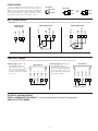
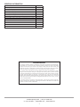
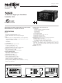
Drawing No. LP0902A Effective 04/13 Tel +1 (717) 767-6511 Fax +1 (717) 764-0839 www.redlion.net PAX2S 1/8 DIN Strain Gage Input Panel Meter Installation Guide C UL R US LISTED 3RSD PROCESS CONTROL EQUIPMENT CERTIFICATIONS AND COMPLIANCES: CE Approved EN 61326-1 Immunity to Industrial Locations Emission CISPR 11 Class A IEC/EN 61010-1 RoHS Compliant UL Listed: File #E179259 Type 4X Indoor Enclosure rating (Face only) IP65 Enclosure rating (Face only) IP20 Enclosure rating (Rear of unit) CONNECTIONS: High compression cage-clamp terminal block Wire Strip Length: 0.3" (7.5 mm) Wire Gauge Capacity: One 14 AWG (2.55 mm) solid, two 18 AWG (1.02 mm) or four 20 AWG (0.61 mm) CONSTRUCTION: This unit is rated NEMA 4X/IP65 for indoor use only. IP20 Touch safe. Installation Category II, Pollution Degree 2. One piece bezel/ case. Flame resistant. Synthetic rubber keypad. Panel gasket and mounting clip included. WEIGHT: 8 oz. (226.8 g) See the Red Lion website at www.redlion.net or the enclosed USB thumbdrive for a complete user manual SPECIFICATIONS POWER: AC Power: 40 to 250 VAC, 50/60 Hz, 20 VA DC Power: 21.6 to 250 VDC, 8 W Isolation: 2300 Vrms for 1 min. to all inputs and outputs. INPUT: Connection Type: 4-wire bridge (differential); 2-wire (single-ended) Common Mode Range (with respect to input common): 0 to +5 VDC Rejection: 80 dB (DC to 120 Hz) Input Ranges: ± 24 mVDC ± 240 mVDC EXCITATION POWER: Jumper selectable +5 VDC @ 65 mADC max., +/-2% +10 VDC @ 125 mADC max., +/-2% Temperature Coefficient (ratio metric): 20 ppm/ºC max. USER INPUTS: Three programmable user inputs Max. Continuous Input: 30 VDC Isolation To Sensor Input Common: Not isolated. CUSTOM LINEARIZATION: Data Point Pairs: Selectable from 2 to 16 Display Range: -199,999 to 999,999 Decimal Point: 0 to 0.0000 ENVIRONMENTAL CONDITIONS: Operating Temperature Range: 0 to 50 °C Storage Temperature Range: -40 to 60 °C Vibration to IEC 68-2-6: Operational 5-150 Hz, 2 g Shock to IEC 68-2-27: Operational 25 g (10 g relay) Operating and Storage Humidity: 0 to 85% max. RH non-condensing Altitude: Up to 2000 meters Note: Recommended minimum clearance (behind the panel) for mounting clip installation is 2.1" (53.4) H x 5.5" (140) W. DIMENSIONS In inches (mm) 1.95 (49.53) 1.75 (44.45) 12 34 3.80 (96.52) 0.10 (2.54) 4.14 (105) 1 3.60 (91.44) SAFETY SUMMARY SETTING THE JUMPERS Bridge Excitation All safety related regulations, local codes and instructions that appear in this literature or on equipment must be observed to ensure personal safety and to prevent damage to either the instrument or equipment connected to it. If equipment is used in a manner not specified by the manufacturer, the protection provided by the equipment may be impaired. Do not use this unit to directly command motors, valves, or other actuators not equipped with safeguards. To do so can be potentially harmful to persons or equipment in the event of a fault to the unit. This jumper is used to select bridge excitation voltage level. Use the 5 V excitation with high output (3 mV/V) bridges, so that the higher sensitivity 24 mV range can be used. Using the 5 V excitation also reduces bridge power consumption compared to the 10 V excitation. A maximum of four 350 ohm load cells can be driven by the internal bridge excitation voltage. JUMPER SELECTIONS The CAUTION: Risk of electric shock. CAUTION: Risk of Danger. Read complete instructions prior to installation and operation of the unit. indicates factory setting. BRIDGE EXCITATION METER INSTALLATION 5V 10V The PAX2S meets NEMA 4X/IP65 requirements when properly installed. The unit is intended to be mounted into an enclosed panel. Prepare the panel cutout to the dimensions shown. Remove the panel latch from the unit. Slide the panel gasket over the rear of the unit to the back of the bezel. The unit should be installed fully assembled. Insert the unit into the panel cutout. While holding the unit in place, push the panel latch over the rear of the unit so that the tabs of the panel latch engage in the slots on the case. The panel latch should be engaged in the farthest forward slot possible. To achieve a proper seal, tighten the latch screws evenly until the unit is snug in the panel (Torque to approximately 7 in-lbs [79N-cm]). Do not over-tighten the screws. INPUT RANGE ±24mV ±240mV REAR TERMINALS FRONT DISPLAY PANEL Main Circuit Board BEZEL LATCHING SLOTS PANEL LATCH USB Connector LATCHING TABS PANEL GASKET Finger Tab PANEL MOUNTING SCREWS Installation Environment The unit should be installed in a location that does not exceed the operating temperature and provides good air circulation. Placing the unit near devices that generate excessive heat should be avoided. REAR TERMINALS PANEL CUT-OUT 3.62 +.03 -.00 (92 +.8 -.0 ) JUMPER LOCATION 1.77+.02 -.00 (45 +.5 -.0 ) 2 Finger Tab POWER WIRING The power supplied to the meter shall employ a 15 Amp UL approved circuit breaker for AC input and a 1 Amp, 250 V UL approved fuse for DC input. It shall be easily accessible and marked as a disconnecting device to the installed unit. This device is not directly intended for connection to the mains without a reliable means to reduce transient over-voltages to 1500 V. AC Power 1 AC/DC 2 AC/DC DC Power + 1 AC/DC - 2 AC/DC OR - 1 AC/DC + 2 AC/DC INPUT SIGNAL WIRING IMPORTANT: Before connecting signal wires, the Input Range Jumper and Bridge Excitation Jumper should be verified for proper position. 4-Wire Bridge Input + EXC +SIG -SIG COMM EXC 5 COMM COMM 4 -SIG - SIG 3 6-Wire Bridge Input +SIG + SIG 2-Wire Single Ended Input 3 4 5 6 3 4 5 6 +SEN +EXC. +SIG. +EXC. -SIG. -SIG. -SEN +SIG. -EXC. -EXC. USER INPUT WIRING If not using User Inputs, then skip this section. User Input terminal does not need to be wired in order to remain in inactive state. Sourcing Logic (USrACt HI) 10 11 USER COMM USER COMM 9 USER 3 USER 3 8 USER 2 USER 2 7 USER INPUTS When the USrACt parameter is programmed to HI, the user inputs of the meter are internally pulled down to 0 V with 20 KW resistance. The input is active when a voltage greater than 2.2 VDC is applied. USER 1 USER 1 USER INPUTS USER COMM When the USrACt parameter is programmed to LO, the user inputs of the meter are internally pulled up to +3.3 V with 20 KW resistance. The input is active when it is pulled low (<1.1 V). USER COMM Sinking Logic (USrACt LO) 7 8 9 10 11 - + V SUPPLY (30V max.) SETPOINT (ALARMS) WIRING SERIAL COMMUNICATION WIRING See appropriate plug-in card bulletin for wiring details. ANALOG OUTPUT WIRING 3 ORDERING INFORMATION DESCRIPTION PART NUMBER Strain Gage Input Panel Meter PAX2S000 Dual Setpoint Relay Output Card PAXCDS10 Quad Setpoint Relay Output Card PAXCDS20 Quad Setpoint Sinking Open Collector Output Card PAXCDS30 Quad Setpoint Sourcing Open Collector Output Card PAXCDS40 RS485 Serial Communications Card with Terminal Block PAXCDC10 Extended RS485 Serial Communications Card with Dual RJ11 Connector PAXCDC1C RS232 Serial Communications Card with Terminal Block PAXCDC20 Extended RS232 Serial Communications Card with 9 Pin D Connector PAXCDC2C DeviceNet Communications Card PAXCDC30 Profibus-DP Communications Card PAXCDC50 Analog Output Card PAXCDL10 LIMITED WARRANTY The Company warrants the products it manufactures against defects in materials and workmanship for a period limited to two years from the date of shipment, provided the products have been stored, handled, installed, and used under proper conditions. The Company’s liability under this limited warranty shall extend only to the repair or replacement of a defective product, at The Company’s option. The Company disclaims all liability for any affirmation, promise or representation with respect to the products. The customer agrees to hold Red Lion Controls harmless from, defend, and indemnify RLC against damages, claims, and expenses arising out of subsequent sales of RLC products or products containing components manufactured by RLC and based upon personal injuries, deaths, property damage, lost profits, and other matters which Buyer, its employees, or sub-contractors are or may be to any extent liable, including without limitation penalties imposed by the Consumer Product Safety Act (P.L. 92-573) and liability imposed upon any person pursuant to the Magnuson-Moss Warranty Act (P.L. 93-637), as now in effect or as amended hereafter. No warranties expressed or implied are created with respect to The Company’s products except those expressly contained herein. The Customer acknowledges the disclaimers and limitations contained herein and relies on no other warranties or affirmations. 20 Willow Springs Circle | York, PA 17406 USA +1 (717) 767-6511 | [email protected] | www.redlion.net 4