1
RN4020 Bluetooth® Low Energy Module
User’s Guide
2014 Microchip Technology Inc.
DS70005191A
Note the following details of the code protection feature on Microchip devices:
•
Microchip products meet the specification contained in their particular Microchip Data Sheet.
•
Microchip believes that its family of products is one of the most secure families of its kind on the market today, when used in the
intended manner and under normal conditions.
•
There are dishonest and possibly illegal methods used to breach the code protection feature. All of these methods, to our
knowledge, require using the Microchip products in a manner outside the operating specifications contained in Microchip’s Data
Sheets. Most likely, the person doing so is engaged in theft of intellectual property.
•
Microchip is willing to work with the customer who is concerned about the integrity of their code.
•
Neither Microchip nor any other semiconductor manufacturer can guarantee the security of their code. Code protection does not
mean that we are guaranteeing the product as “unbreakable.”
Code protection is constantly evolving. We at Microchip are committed to continuously improving the code protection features of our
products. Attempts to break Microchip’s code protection feature may be a violation of the Digital Millennium Copyright Act. If such acts
allow unauthorized access to your software or other copyrighted work, you may have a right to sue for relief under that Act.
Information contained in this publication regarding device
applications and the like is provided only for your convenience
and may be superseded by updates. It is your responsibility to
ensure that your application meets with your specifications.
MICROCHIP MAKES NO REPRESENTATIONS OR
WARRANTIES OF ANY KIND WHETHER EXPRESS OR
IMPLIED, WRITTEN OR ORAL, STATUTORY OR
OTHERWISE, RELATED TO THE INFORMATION,
INCLUDING BUT NOT LIMITED TO ITS CONDITION,
QUALITY, PERFORMANCE, MERCHANTABILITY OR
FITNESS FOR PURPOSE. Microchip disclaims all liability
arising from this information and its use. Use of Microchip
devices in life support and/or safety applications is entirely at
the buyer’s risk, and the buyer agrees to defend, indemnify and
hold harmless Microchip from any and all damages, claims,
suits, or expenses resulting from such use. No licenses are
conveyed, implicitly or otherwise, under any Microchip
intellectual property rights.
Trademarks
The Microchip name and logo, the Microchip logo, dsPIC,
FlashFlex, KEELOQ, KEELOQ logo, MPLAB, PIC, PICmicro,
PICSTART, PIC32 logo, rfPIC, SST, SST Logo, SuperFlash
and UNI/O are registered trademarks of Microchip Technology
Incorporated in the U.S.A. and other countries.
FilterLab, Hampshire, HI-TECH C, Linear Active Thermistor,
MTP, SEEVAL and The Embedded Control Solutions
Company are registered trademarks of Microchip Technology
Incorporated in the U.S.A.
Silicon Storage Technology is a registered trademark of
Microchip Technology Inc. in other countries.
Analog-for-the-Digital Age, Application Maestro, BodyCom,
chipKIT, chipKIT logo, CodeGuard, dsPICDEM,
dsPICDEM.net, dsPICworks, dsSPEAK, ECAN,
ECONOMONITOR, FanSense, HI-TIDE, In-Circuit Serial
Programming, ICSP, Mindi, MiWi, MPASM, MPF, MPLAB
Certified logo, MPLIB, MPLINK, mTouch, Omniscient Code
Generation, PICC, PICC-18, PICDEM, PICDEM.net, PICkit,
PICtail, REAL ICE, rfLAB, Select Mode, SQI, Serial Quad I/O,
Total Endurance, TSHARC, UniWinDriver, WiperLock, ZENA
and Z-Scale are trademarks of Microchip Technology
Incorporated in the U.S.A. and other countries.
SQTP is a service mark of Microchip Technology Incorporated
in the U.S.A.
GestIC and ULPP are registered trademarks of Microchip
Technology Germany II GmbH & Co. KG, a subsidiary of
Microchip Technology Inc., in other countries.
All other trademarks mentioned herein are property of their
respective companies.
© 2014, Microchip Technology Incorporated, Printed in the
U.S.A., All Rights Reserved.
Printed on recycled paper.
ISBN: 978-1-63276-306-8
QUALITY MANAGEMENT SYSTEM
CERTIFIED BY DNV
== ISO/TS 16949 ==
DS70005191A-page 2
Microchip received ISO/TS-16949:2009 certification for its worldwide
headquarters, design and wafer fabrication facilities in Chandler and
Tempe, Arizona; Gresham, Oregon and design centers in California
and India. The Company’s quality system processes and procedures
are for its PIC® MCUs and dsPIC® DSCs, KEELOQ® code hopping
devices, Serial EEPROMs, microperipherals, nonvolatile memory and
analog products. In addition, Microchip’s quality system for the design
and manufacture of development systems is ISO 9001:2000 certified.
2014 Microchip Technology Inc.
Object of Declaration: RN4020 Bluetooth® Low Energy Module
2014 Microchip Technology Inc.
DS70005191A-page 3
RN4020 Bluetooth Low Energy Module User’s Guide
NOTES:
DS70005191A-page 4
2014 Microchip Technology Inc.
RN4020 BLUETOOTH LOW
ENERGY MODULE USER’S GUIDE
Table of Contents
Preface ........................................................................................................................... 7
Chapter 1. Introduction
1.1 Bluetooth Low Energy Fundamentals .......................................................... 13
Chapter 2. RN4020 OEM Module Interface
2.1 RN4020 Control Lines .................................................................................. 15
2.2 RN4020 UART Control Interface .................................................................. 19
2.3 Device Firmware Upgrade ............................................................................ 59
Chapter 3. Application Examples
3.1 Demonstration with a Smart Device ............................................................. 61
3.2 Connecting Two RN4020 Modules ............................................................... 71
3.3 MLDP Demonstration ................................................................................... 74
3.4 RN4020 Scripting Demonstration ................................................................. 75
Appendix A. PICtail™ Daughter Board Schematics ................................................. 77
Worldwide Sales and Service .................................................................................... 84
2014 Microchip Technology Inc.
DS70005191A-page 5
RN4020 Bluetooth Low Energy Module User’s Guide
NOTES:
DS70005191A-page 6
2014 Microchip Technology Inc.
RN4020 BLUETOOTH LOW ENERGY
MODULE USER’S GUIDE
Preface
NOTICE TO CUSTOMERS
All documentation becomes dated, and this manual is no exception. Microchip tools and
documentation are constantly evolving to meet customer needs, so some actual dialogs
and/or tool descriptions may differ from those in this document. Please refer to our web site
(www.microchip.com) to obtain the latest documentation available.
Documents are identified with a “DS” number. This number is located on the bottom of each
page, in front of the page number. The numbering convention for the DS number is
“DSXXXXXXXXA”, where “XXXXXXXX” is the document number and “A” is the revision level
of the document.
For the most up-to-date information on development tools, see the MPLAB® IDE online help.
Select the Help menu, and then Topics to open a list of available online help files.
INTRODUCTION
This chapter contains general information that will be useful to know before using the
RN4020 Bluetooth® Low Energy Module. Items discussed in this chapter include:
•
•
•
•
•
•
•
Document Layout
Conventions Used in this Guide
Recommended Reading
The Microchip Web Site
Development Systems Customer Change Notification Service
Customer Support
Document Revision History
DOCUMENT LAYOUT
This document describes how to use the RN4020 Bluetooth® Low Energy Module as a
development tool to emulate and debug firmware on a target board. This document
includes the following chapters:
• Chapter 1. “Introduction” provides a brief overview of the RN4020, highlighting
its features and uses.
• Chapter 2. “RN4020 OEM Module Interface” provides information on the
module interface.
• Chapter 3. “Application Examples” provides application examples that
emphasize the features of the RN4020.
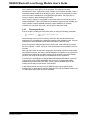
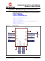
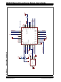
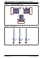
• Appendix A. “PICtail™ Daughter Board Schematics” provides schematic
diagram information for the PICtail Daughter Board.
2014 Microchip Technology Inc.
DS70005191A-page 7
RN4020 Bluetooth Low Energy Module User’s Guide
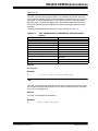
CONVENTIONS USED IN THIS GUIDE
This manual uses the following documentation conventions:
DOCUMENTATION CONVENTIONS
Description
Italic characters
Initial caps
Examples
Referenced books
MPLAB® IDE User’s Guide
Emphasized text
...is the only compiler...
A window
the Output window
A dialog
the Settings dialog
A menu selection
select Enable Programmer
Quotes
A field name in a window or
dialog
“Save project before build”
Underlined, italic text with
right angle bracket
A menu path
File > Save
Bold characters
A dialog button
Click OK
A tab
Click the Power tab
Text in angle brackets < >
A key on the keyboard
Press <Enter>, <F1>
Plain Courier New
Sample source code
#define START
Filenames
autoexec.bat
File paths
c:\mcc18\h
Keywords
_asm, _endasm, static
Command-line options
-Opa+, -Opa-
Bit values
0, 1
Constants
0xFF, ‘A’
Italic Courier New
A variable argument
file.o, where file can be any
valid filename
Square brackets [ ]
Optional arguments
mcc18 [options] file
[options]
Curly brackets and pipe
character: { | }
Choice of mutually exclusive
arguments; an OR selection
errorlevel {0|1}
Ellipses...
Replaces repeated text
var_name [, var_name...]
Represents code supplied by
user
void main (void)
{ ...
}
Notes
DS70005191A-page 8
Represents
A Note presents information
that we want to re-emphasize,
either to help you avoid a
common pitfall or to make you
aware of operating differences
between some device family
members. A Note can be in a
box, or when used in a table
or figure, it is located at the
bottom of the table or figure.
Note:
This is a standard
note box.
CAUTION
This is a caution note.
Note 1: This is a note used in a
table.
2014 Microchip Technology Inc.
RECOMMENDED READING
The following documents are recommended as supplemental reference resources.
RN4020 Family Data Sheet (DS50002279)
Consult this document for detailed information on the RN4020 Bluetooth® Low Energy
Module. Reference information found in this data sheet includes:
• Device pinout and packaging details
• Device electrical specifications
• List of features included on the device
This document is available for download from the Microchip website
(www.microchip.com).
Bluetooth Core Specification v4.0, 30 June 2010
This specification is available for download from www.bluetooth.org.
Bluetooth Core Specification v4.1, 3 December 2013
Bluetooth® Core Specification 4.1 is an important evolutionary update to the Bluetooth
Core Specification. It rolls up adopted Bluetooth Core Specification Addenda (CSA 1,
2, 3, and 4) while adding new features and benefits. Bluetooth 4.1 improves usability
for consumers, empowers innovation for product developers, and extends the technology's foundation as an essential link for the Internet of Things.
This specification is available for download from www.bluetooth.org.
2014 Microchip Technology Inc.
DS70005191A-page 9
RN4020 Bluetooth Low Energy Module User’s Guide
THE MICROCHIP WEB SITE
Microchip provides online support via our web site at: http://www.microchip.com. This
web site makes files and information easily available to customers. Accessible by most
Internet browsers, the web site contains the following information:
• Product Support – Data sheets and errata, application notes and sample
programs, design resources, user’s guides and hardware support documents,
latest software releases and archived software
• General Technical Support – Frequently Asked Questions (FAQs), technical
support requests, online discussion groups, Microchip consultant program
member listings
• Business of Microchip – Product selector and ordering guides, latest Microchip
press releases, listings of seminars and events; and listings of Microchip sales
offices, distributors and factory representatives
DEVELOPMENT SYSTEMS CUSTOMER CHANGE NOTIFICATION SERVICE
Microchip’s customer notification service helps keep customers current on Microchip
products. Subscribers will receive e-mail notification whenever there are changes,
updates, revisions or errata related to a specified product family or development tool of
interest.
To register, access the Microchip web site at www.microchip.com, click on Customer
Change Notification and follow the registration instructions.
The Development Systems product group categories are:
• Compilers – The latest information on Microchip C compilers and other language
tools
• Emulators – The latest information on the Microchip in-circuit emulator, MPLAB®
REAL ICE™
• In-Circuit Debuggers – The latest information on the Microchip in-circuit
debugger, MPLAB ICD 3
• MPLAB X IDE – The latest information on Microchip MPLAB X IDE, the
Windows® Integrated Development Environment for development systems tools
• Programmers – The latest information on Microchip programmers including the
PICkit™ 3 development programmer
CUSTOMER SUPPORT
Users of Microchip products can receive assistance through several channels:
•
•
•
•
Distributor or Representative
Local Sales Office
Field Application Engineer (FAE)
Technical Support
Customers should contact their distributor, representative or field application engineer
(FAE) for support. Local sales offices are also available to help customers. A listing of
sales offices and locations is included in the back of this document.
Technical support is available through the web site at: http://support.microchip.com
DS70005191A-page 10
2014 Microchip Technology Inc.
DOCUMENT REVISION HISTORY
Revision A (June 2014)
Initial release of this document.
2014 Microchip Technology Inc.
DS70005191A-page 11
RN4020 Bluetooth Low Energy Module User’s Guide
NOTES:
DS70005191A-page 12
2014 Microchip Technology Inc.
RN4020 BLUETOOTH LOW ENERGY
MODULE USER’S GUIDE
Chapter 1. Introduction
This chapter introduces the RN4020 module and includes the following topic:
• Bluetooth Low Energy Fundamentals
The RN4020 Bluetooth® Low Energy Module is a single mode Bluetooth Smart module
that complies with Bluetooth Core Specification v4.1.
Through its high-speed UART interface, this module can be configured to act as either
a central or peripheral role when establishing a connection. This module supports 13
public profiles and 17 public services, which are adopted by the Bluetooth Special Interest Group (SIG).
For all supported profiles and services, the RN4020 module can be configured to act
as server and client roles at the same time. Furthermore, the RN4020 module supports
the private Microchip Low-energy Data Profile (MLDP), which provides an
asynchronous serial data connection between two RN4020 devices.
Finally, the Microchip RN4020 module also supports a user-defined private profile/service, which can precisely fit a user's particular application. All configurations will be
saved in on-board non-volatile memory (NVM), so users need to set up the module only
once.
The Microchip RN4020 module is easy to use and provides users with a fast-to-market,
flexible, and powerful solution for BTLE technology.
1.1
BLUETOOTH LOW ENERGY FUNDAMENTALS
When two BTLE devices need to be connected, one is in a central role and the other
in a peripheral role. The peripheral advertises its connection status, while the central
device starts the connection process. Once connected, either end of the connection
can initiate the bond. Once bonded, all security-related keys will be saved and the
security process will be waived when reconnecting. The bonded peripheral device can
only perform direct advertise; therefore, it is no longer able to connect to devices other
than its bonded peer.
Similar to Bluetooth Classic, BTLE uses the concept of profiles to ensure interoperability between different devices. However, unlike Bluetooth Classic, BTLE profiles are a
collection of services. All BTLE services are built on top of the Generic Attribute Profile
(GATT), where GATT defines the accessibility of attributes, which are called characteristics. Therefore, the main functionality of BTLE profiles is built around these characteristics. Devices that maintain the value of characteristics in a service are the “server”
of the service. Conversely, devices that acquire data from their peer are considered the
“client”.
Each service and its characteristics are identified by their Universally Unique Identifier
(UUID). The UUID can either be short form (16-bit) or long form (128-bit). All Bluetooth
SIG adopted services and characteristics have a short UUID, whereas a user-defined
private UUID must be in long form. For information on the Bluetooth SIG adopted services and characteristics, visit the Bluetooth Developer Portal at: https://developer.bluetooth.org/gatt/profiles/Pages/ProfilesHome.aspx.
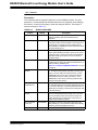
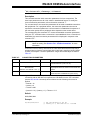
The accessibility of each characteristic is defined by the 8-bit characteristic property in
bitmap format, as shown in Table 1-1.
2014 Microchip Technology Inc.
DS70005191A-page 13
RN4020 Bluetooth Low Energy Module User’s Guide
TABLE 1-1:
CHARACTERISTIC PROPERTIES
Property
Bitmap
Description
Extended Property(1)
0‘b10000000 Additional property available.
Authenticated Write(1)
0‘b01000000 Write characteristic with authentication from client to server.
Indicate
0‘b00100000 Indicate value of characteristic with acknowledgment from server to client.
Notify
0‘b00010000 Notify value of characteristic without acknowledgment from server to client.
Write
0‘b00001000 Write value of characteristic with acknowledgment from client to server.
Write Without Response 0‘b00000100 Write value of characteristic without acknowledgment from client to server.
Read
0‘b00000010 Read value of characteristic. Value is sent from server to client.
Broadcast
0‘b00000001 Broadcast value of characteristic.
Note 1:
The RN4020 does not currently support this property.
DS70005191A-page 14
2014 Microchip Technology Inc.
RN4020 BLUETOOTH LOW ENERGY
MODULE USER’S GUIDE
Chapter 2. RN4020 OEM Module Interface
This chapter describes the interface for the RN4020 module.
The RN4020 module is a fully agent certified Bluetooth Low Energy single mode
OEM module. The module is controlled by the user through input/output lines (i.e.,
physical device pins) and a UART interface.
The following topics are included:
• RN4020 Control Lines
• RN4020 UART Control Interface
• Device Firmware Upgrade
2.1
RN4020 CONTROL LINES
The RN4020 module uses the WAKE_SW (pin 7), CMD/MLDP (pin 8), WAKE_HW
(pin 15) pins to place the module into different states, and three output pins to
indicate its current status.
WAKE_SW is used to control the operating state of the RN4020. When WAKE_SW is
set high, the module wakes up and is set into Active mode. Upon waking up, “CMD”
will be output to the UART and indicate that the module is in Command mode and
ready to take commands from UART. Conversely, when WAKE_SW is set low, the
module exits Command mode by outputting “END” to the UART, and then operates in
Deep Sleep mode. The UART interface will not be responsive in Deep Sleep mode
unless the UART baud rate is 2400 bps. When the module is in Deep Sleep mode,
MLDP_EV (pin 11) will be output low.
CMD/MLDP (pin 8) is used to control the RN4020 module when an MLDP serial data
service (see Section 2.2.5 “Microchip MLDP Commands”) is used. Once MLDP
mode is entered by setting CMD/MLDP high, all data from the UART is sent to the
peer device as a data stream. To exit MLDP mode, CMD/MLDP must be set low so
that the RN4020 module is returned to Command mode by outputting “CMD” to the
UART.
Setting WAKE_HW (pin 15) high wakes the RN4020 module from Dormant mode.
After powering up, if WAKE_HW flips up and down three cycles (putting the
WAKE_HW pin into high, and then low, and then high again is considered one flip
cycle) in the first five seconds, the RN4020 module performs a factory Reset. If
WAKE_SW is high when a factory Reset is performed, the factory Reset is complete;
otherwise, it is a partial factory Reset that retains the device name, private service,
and scripts.
When the RN4020 module is connected to a peer device, CONNECTION LED (pin
10) will output high; otherwise, CONNECTION LED outputs low.
When in MLDP mode, if the RN4020 module must output a status to the UART or is
requesting a response from the host MCU, MLDP_EV will be set high. Once the
RN4020 module exits MLDP mode and returns to Command mode, status and/or
requests will be output to the UART. Once stored data is output to the UART,
MLDP_EV will be set low. The maximum buffer size of status and requests is 256
bytes. When the RN4020 module is in Active mode, WS (pin 12) will be output high;
otherwise, it outputs low.
2014 Microchip Technology Inc.
DS70005191A-page 15
RN4020 Bluetooth Low Energy Module User’s Guide
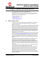
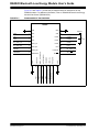
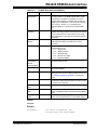
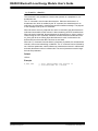
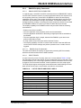
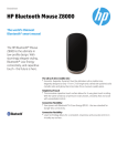
Figure 2-1 and Table 2-1 provide the pin diagram and their descriptions for the
RN4020 module. For additional information, refer to “RN4020 Bluetooth Low Energy
Module Data Sheet” (DS50002279).
FIGURE 2-1:
RN4020 MODULE PIN DIAGRAM
RN4020
24
VDD3V3
23
RSVD3
21
RSVD2
20
RSVD1
19
PIO7
18
BT_UART_RTS
17
SPI_PIO
C1
4.7 μF
GND
22
16
15
BT_WAKE
WAKE_HW
SPI/PIO
CTS/PIO5
CMD/MLDP
9
DS70005191A-page 16
RTS/PIO6
WAKE_SW
14
8
PIO7
PIO4/MISO
CMD/MLDP
UART_RX
BT_UART_CTS
7
RSVD
13
SWAKE
UART_TX
PIO4
6
RSVD
WS/PIO3/MOSI
BT_UART_RX
AIO0
12
5
PIO3
BT_UART_TX
MLDP_EV/PIO2/CS
4
RSVD
11
AIO0
AIO1
PIO2
3
VDD
PIO1/SCK
AIO1
AIO2
10
2
GND
AIO2
GND
GND
PIO1
1
2014 Microchip Technology Inc.
RN4020 OEM Module Interface
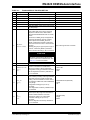
TABLE 2-1:
Pin
RN4020 MODULE PIN DESCRIPTION
Symbol
1
2
3
4
5
6
GND
AIO2
AIO1
AIO0
UART TX
UART RX
7
WAKE_SW
8
CMD/MLDP
FACTORY RESET
Description
Ground.
Bidirectional with programmable analog I/O.
Bidirectional with programmable analog I/O.
Bidirectional with programmable analog I/O.
UART Transmit (TX).
UART Receive (RX).
Function
Ground
1.65V input, 1.35V out, and 30 mA max out
1.65V input, 1.35V out, and 30 mA max out
1.65V input, 1.35V out, and 30 mA max out
Output from RN4020
Input to RN4020
Deep Sleep Wake; active-high to wake module
Input; weak pull-down
from Deep Sleep.
Command or MLDP mode – In Command
mode, UART traffic is sent to the command
interpreter. In MLDP mode, UART traffic is
routed to the MLDP Bluetooth LED connection,
if active.
At boot time, if WAKE_HW pin is flipped three
times within the first five seconds, a factory
Reset is performed. If WAKE_SW is low
(default) a partial factory Reset is performed,
which is the same as if a “SF,1” command were
executed.
Input; active-high to enter Command
If WAKE_SW (pin7) is high and pin8 is high at
boot time, a full factory Reset is performed,
which is similar to executing a “SF,2” command.
CAUTION
A full factory reset erases scripts and sets
the device name to the serialized name. See
the SF,<1,2> command for details.
9
GND
10
CONNECTION LED
PIO[1]
SCK
11
MLDP_EV
PIO[2]
CS
12
WS
PIO[3]
MOSI
Ground.
Default state is output: Active-high indicates the
module is connected to a remote device.
Active-high indicates a disconnected state.
Configurable as PIO[1] via software command.
SCK for diagnostics and factory calibration if
pin 17 is asserted.
Default function is output used for MLDP data
event indicator (red LED). Active-high indicates
MLDP data received or UART console data
pending. Low level indicates no events. Event
only triggered in CMD mode, when CMD/MLDP
(pin 8) is high.
Configurable as PIO[2] via “|O” and “|I”
commands.
CS for diagnostics and factory calibration if pin
17 is asserted.
Default function is an output used for an Activity
indicator (blue LED). High level indicates the
module is awake and active. Low level
indicates the module is in a Sleep state.
Accessible as PIO[3] via “|O” and “|I”
commands.
MOSI for diagnostics and factory calibration if
pin 17 is asserted.
2014 Microchip Technology Inc.
Ground
• Green LED
• PIO[1]
• SCK
• MLDP Data Event (Red LED)
• PIO[2]
• CS
• WS (Blue LED)
• PIO[3]
• MOSI
DS70005191A-page 17
RN4020 Bluetooth Low Energy Module User’s Guide
TABLE 2-1:
Pin
RN4020 MODULE PIN DESCRIPTION (CONTINUED)
Symbol
Description
Trigger pin to generate event @PIOH and
@PIOL.
MISO for diagnostics and factory calibration if
pin 17 asserted.
13
PIO[4]
MISO
14
CTS
PIO[5]
15
WAKE_HW
16
GND
Ground.
17
SPI/PIO
SPI/PIO for pins 10-13, active-high.
18
PIO[6]
19
PIO[7]
20
21
22
23
24
RSVD
RSVD
RSVD
VDD
GND
DS70005191A-page 18
Function
• PIO[4]
• MISO
Reserved for CTS if hardware flow control is on • CTS (input)
the UART.
• PIO[5]
Hardware wake from Hibernate or Dormant
Active-high; internal pull down
state.
Reserved for RTS if hardware flow control on
UART. Configurable as PIO[6] if hardware flow
control is disabled.
Spare PIO. Refer to Section 2.2.2 “Action
Commands” for the “|O” and “|I” commands.
Do not connect. Factory diagnostics.
Do not connect. Factory diagnostics.
Do not connect. Factory diagnostics.
Supply voltage.
Ground.
Ground
Input with internal pull down; selects SPI on
10-13
• RTS (output)
• PIO[6]
Spare PIO configurable as input or output
No Connect
No Connect
No Connect
1.8 to 3.6V
Ground
2014 Microchip Technology Inc.
RN4020 OEM Module Interface
2.2
RN4020 UART CONTROL INTERFACE
The UART is the main control interface for the RN4020 module. The default UART
port configuration is shown in Table 2-2.
TABLE 2-2:
RN4020 UART CONFIGURATION
Parameter
Value
Baud Rate
115200
Data Bits
8
Parity
None
Stop Bits
1
Flow Control
None
The UART baud rate can be adjusted from 2400 to 932 Kbps with the “SB”
command. When the UART baud rate is set to 2400, there is no need to wake the
module via WAKE_SW (pin 7) before communicating with the module.
All control takes place through ASCII commands and their parameters. All commands
and parameters are separated by commas. No spaces are allowed between
commands and parameters. All commands are completed by either a line feed or a
return.
All commands are divided into the following types:
•
•
•
•
•
•
•
•
Set/Get Commands
Action Commands
Characteristic Access Commands
Private Service Configuration Commands
Microchip MLDP Commands
RN4020 Scripting Commands
Remote Command
DFU Commands
Table 2-3 lists and provides brief descriptions of all commands by type.
TABLE 2-3:
Type
Set/Get
2014 Microchip Technology Inc.
COMMAND DESCRIPTIONS
Command Name
Description
S-
Serialized name
SB
Set UART baud rate
SDF
Set firmware revision
SDH
Set hardware revision
SDM
Set model name
SDN
Set manufacturer name
SDR
Set software revision
SDS
Set serial number
SF
Factory default
SM
Set Timers in μs
SN
Set name
SR
Set features
SS
Set server services
ST
Set connection parameters
DS70005191A-page 19
RN4020 Bluetooth Low Energy Module User’s Guide
TABLE 2-3:
Type
Action
Services
Private Services
MLDP
COMMAND DESCRIPTIONS (CONTINUED)
Command Name
+
DS70005191A-page 20
Echo
@O
Output analog signal
@I
Input analog signal
|O
Set PIO’s output
|I
Get PIO’s input
A
Advertise
B
Bond
D
Dump configuration
E
Establish connection
F
Start scan
H
Help
J
Observer role
K
Disconnect
M
Get RSSI from peer
N
Enter broadcast information
O
Enter dormant state
R
Reboot
T
Change parameter for current connection
U
Unbond
V
Firmware version
X
Stop scan
Y
Stop advertisement
Z
Stop connecting
LC
List client services
LS
List server services
CHR
Read value from client handle
CHW
Write value of client handle
CURC
Read configuration of client UUID
CURV
Read value of client UUID
CUWC
Client UUID notify/indicate start
CUWV
Write value to client UUID
SHR
Read value of server handle
SHW
Write value to server handle
SUR
Read value of server UUID
SUW
Write value to server UUID
PC
Set private characteristic UUID
PS
Set private service UUID
PZ
Clear private service
SE
Set MLDP security mode
I
Scripting
Description
Enter MLDP mode
LW
Show script
WC
Clear script
WP
Pause script
WR
Run script
WW
Write script
2014 Microchip Technology Inc.
RN4020 OEM Module Interface
TABLE 2-3:
Type
COMMAND DESCRIPTIONS (CONTINUED)
Command Name
Description
Remote
!
Enter Remote Command mode
DFU
~
Device Firmware Update
2.2.1
Set/Get Commands
This group of commands is used to configure specific functions of the RN4020
module. The Set commands start with the letter S and are followed by one or two
letters as the command identifier. The Set command parameters are mandatory and
are separated from the command by a comma. The format of the Set commands is
provided in Example 2-1.
EXAMPLE 2-1:
S
SET COMMAND FORMAT
Command Identifier
,
Input Parameter
A reboot is required for most Set commands to ensure the new settings will take
effect. Configurations from the Set commands are stored in the non-volatile memory
(NVM) of the RN4020 module and restored after a power cycle or reset. All Set
commands have a corresponding Get command to output the configurations to the
UART. Get commands have the same command identifier as Set commands, but
have no parameters.
S-,<string>
Description
This command sets the serialized Bluetooth-friendly name of the device, where
<string> is up to 15 alphanumeric characters. This command automatically appends
the last 2 bytes of the Bluetooth MAC address to the name, which is useful for
generating a custom name with unique numbering.
Default:
Not applicable.
Example
S-,MyDevice
2014 Microchip Technology Inc.
// Set device name to “MyDevice-ABCD”
DS70005191A-page 21
RN4020 Bluetooth Low Energy Module User’s Guide
SB,<0-7>
Description
This command sets the baud rate of the UART communication. The input parameter
is a single digit number in the range of 0 to 7, representing a baud rate from 2400 to
921K, as shown in Table 2-4. When the baud rate is set to 2400, there is no need to
wake the RN4020 module by pulling WAKE_SW high for UART communication.
TABLE 2-4:
UART BAUD RATE SETTINGS
Setting
Baud Rate
Comments
0
2400
When the UART is set to 2400 Kbps, the RN4020
module can remain in Deep Sleep. In other
words, when set to 2400 Kbps, the UART is
always accessible; therefore, the WAKE_SW line
does not need to be pulled high to wake the
RN4020 module for UART access.
1
9600
—
2
19200
—
3
38400
—
4
115200
—
5
230400
—
6
460800
—
7
921600
—
SDF,<text>
Description
This command sets the value of the firmware revision characteristic in the Device
Information Service.
The Device Information Service is used to identify the device. Since all of its
characteristics rarely change, the values of the characteristics in the Device
Information Service can be set and saved into NVM. All characteristic values in the
Device Information Service have a maximum size of 20 bytes.
Default:
Determined by firmware version.
Example
SDF,0.9
DS70005191A-page 22
2014 Microchip Technology Inc.
RN4020 OEM Module Interface
SDH,<text>
Description
This command sets the value of the hardware revision characteristics in the Device
Information Service.
Default
Determined by hardware version.
Example
SDH,2.1
SDM,<text>
Description
This command sets the value of the model characteristics in the Device Information
Service.
Default
RN4020
Example
SDM,RN4020
SDN,<text>
Description
This command sets the value of the manufacturer name characteristics in the Device
Information Service.
Default
Microchip
Example
SDN,Microchip
2014 Microchip Technology Inc.
DS70005191A-page 23
RN4020 Bluetooth Low Energy Module User’s Guide
SDR,<text>
Description
This command sets the value of the software revision characteristics in the Device
Information Service.
Default
Determined by software version.
Example
SDR,1.0
SDS,<text>
This command sets the value of the serial number characteristics in the Device
Information Service.
Default
The MAC address of the device.
Example
SDS,12345678
SF,<1,2>
This command resets the configurations to the factory default at the next reboot. The
parameters of this command are ‘1’ and ‘2’.
When the input parameter is ‘1’, a majority of the settings will be restored to the
factory default, but some settings, such as device name, device info, script and
private services, stay the same. When the input parameter is ‘2’, all parameters are
restored to factory default.
Default
Not applicable.
Example
SF,1
DS70005191A-page 24
2014 Microchip Technology Inc.
RN4020 OEM Module Interface
SM,<1-3>,<hex32>
This command starts one of the application timers. The first parameter is the identifier
of the timer to start, and the second parameter is the timer expiration time in
microseconds if the value is in the range between 0x00000001 and 0x7FFFFFFF.
The second parameter outside the this range will stop the timer.
Default
Not applicable.
Example
SM,1,000f4240
// Start Timer1 to expire in 1 second
SM,1,FFFFFFFF
// Stop Timer1 immediately
SN,<string>
Description
This command sets the device name, where <string> is up to 20 alphanumeric
characters.
Default
Not applicable.
Example
SN,MyDevice
2014 Microchip Technology Inc.
// Set the device name to “MyDevice”
DS70005191A-page 25
RN4020 Bluetooth Low Energy Module User’s Guide
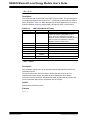
SR,<hex32>
Description
This command sets the supported features of current RN4020 module. The input
parameter is a 32-bit bitmap that indicates features to be supported. After changing
the features, a reboot is necessary to make the changes effective. The bitmap of
features is shown in Table 2-5.
TABLE 2-5:
Feature
DS70005191A-page 26
BITMAP FEATURES
Bitmap
Description
Central
0x80000000
If set, the device that starts the connection is central. If
cleared, the device that starts advertisement is
peripheral.
Real-time Read
0x40000000
If set, the device request values from the host MCU
through the UART and the host MCU must respond in a
timely manner. If cleared, the device reads from the
internal RAM of the RN4020 for the characteristic values
that were previously set.
Auto Advertise
0x20000000
This setting only applies to a peripheral device. If set, the
device starts advertisement after a power cycle, reboot,
or disconnection. If cleared, the device starts advertisement after receiving command “A” from the UART in
Command mode.
Support MLDP
0x10000000
If set, the device supports the private service MLDP that
provides asynchronous serial data over Bluetooth LE. If
cleared, MLDP is disabled. See
Section 2.2.5 “Microchip MLDP Commands” for more
information.
Auto MLDP
Disable
0x08000000
This setting is only effective when MLDP is enabled. If
set, the device enters MLDP mode after receiving command “I” from the UART in Command mode, or when
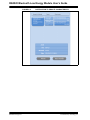
CMD/MLDP (pin 8) is set high. If cleared, the device
enters MLDP mode not only by command “I” or the
CMD/MLDP pin, but also by receiving an MLDP data
stream from the peer device.
No Direct
Advertisement
0x04000000
This setting is only effective for peripheral devices. If set,
the peripheral will not issue a direct advertisement even
if it is bonded; therefore, it is discoverable whenever it is
advertising. This setting is useful when working with iOS
or Android devices.
UART Flow
Control
0x02000000
This setting is used to control RTS/CTS hardware flow
control on the RN4020 module UART port. If set, flow
control is enabled and the host needs to support the
UART hardware flow control feature. Flow control is
required when MLDP is enabled.
Run Script After
Power On
0x01000000
This setting is used to control script execution. If set,
after powering on, script execution will be automatically
started by generating a @PW_ON event.
Reserved
0x00800000
—
2014 Microchip Technology Inc.
RN4020 OEM Module Interface
TABLE 2-5:
Feature
BITMAP FEATURES (CONTINUED)
Bitmap
Description
Enable
Authentication
0x00400000
This setting enables authentication during connection,
preventing a Man-In-The-Middle (MITM) attack. When
authentication is enabled, I/O capability is set to be
keyboard and/or display. For details, refer to Table 2.5:
“Mapping of IO Capabilities to STK Generation Method”
in Vol 3, Part H, Section 2.3.5.1 “Selecting STK
Generation Method” in “Bluetooth Core Specification
v4.1”.
Enable Remote
Command
0x00200000
This setting is only effective if the MLDP feature is
enabled. This setting enables the local device to receive
remote commands from a remote device and to send
command output to a remote device through the MLDP
data stream.
Do not Save
Bonding
0x00100000
Once set, the bonding information will not be saved in
NVM and the bonding is only valid for the current
connection.
I/O Capabilities
0x000E0000
I/O capability of the module. Only useful if the Enable
Authentication bit is set.
• ‘b000 = Display Only
• ‘b001 = Display Yes/No
• ‘b010 = Keyboard Only
• ‘b011 = No Input, no output
• ‘b100 = Keyboard Display
Block Set
Commands in
Remote
Command Mode
0x00010000
If set, all “Set” commands are no longer effective in
Remote Command mode.
Enable OTA
0x00008000
If set, DFU over the air is effective. Otherwise, support of
DFU OTA is disabled.
iOS Mode
0x00004000
If set, connection parameters will be checked against
Apple® Bluetooth Accessory Design Guidelines. See the
ST,<interval>,<latency>,<timeout> command for
details.
Server Only
0x00002000
If set, the RN4020 module will not act as a client. No service discovery will be performed after connection to save
connection time and power.
Enable UART in
Script
0x00001000
If set, allow normal UART output when running a script.
Auto-enter MLDP
Mode
0x00000800
If set, and the Support MLDP bit is also set, once connected, the RN4020 module automatically enters MLDP
mode.
MLDP without
Status
0x00000400
If set, no additional status string, such as “CMD”, “Connected”, and “Connection End”, is in the UART output.
Default
00000000
Example
SR,20000000
2014 Microchip Technology Inc.
// Set device as peripheral, and
// automatically start advertisement
DS70005191A-page 27
RN4020 Bluetooth Low Energy Module User’s Guide
SS,<hex32>
Description
This command sets the services supported by the device in a server role. The input
parameter is a 32-bit bitmap that indicates the services supported as a server.
Supporting the service-as-server role means that the host MCU needs to supply the
values of all characteristics in the supported services and provides client access to
those values upon request. The values for the service characteristics are written to
the server database using ‘SSW’ commands. Once the service bitmap is modified,
the device must reboot to make the new services effective. The 32-bit bitmap is
provided in Table 2-6.
TABLE 2-6:
BITMAP SERVICES
Service
Device Information
Bitmap
Used in Profiles
0x80000000 Blood Pressure, Cycling Speed Cadence,
Glucose, Health Thermometer, Heart Rate,
Running Speed Cadence
Battery
0x40000000
Heart Rate
0x20000000 Heart Rate
Health Thermometer
0x10000000 Health Thermometer
Glucose
0x08000000 Glucose
Blood Pressure
0x04000000 Blood Pressure
Running Speed Cadence
0x02000000 Running Speed Cadence
Cycling Speed Cadence
0x01000000 Cycling Speed Cadence
Current Time
0x00800000 Time
Next DST Change
0x00400000 Time
Reference Time Update
0x00200000 Time
Link Loss
0x00100000 Proximity
Immediate Alert
0x00080000 Find Me, Proximity
TX Power
0x00040000 Proximity
Alert Notification
0x00020000 Alert Notification
Phone Alert Status
0x00010000 Phone Alert Status
Scan Parameters
0x00004000 Scan Parameters
User Defined Private Service 0x00000001 User Defined Private Profile
Default
80000000
Example
SS,060000
DS70005191A-page 28
// Support blood pressure and running speed
// cadence as server role
2014 Microchip Technology Inc.
RN4020 OEM Module Interface
ST,<interval>,<latency>,<timeout>
Description
This command sets the initial connection parameters for future connections. The
three input parameters are all 16-bit values in hexadecimal format. To modify the
current connection parameters, refer to the action command “T”.
For a central device, the connection parameters will be used to establish connections
with peripherals. For a peripheral device, the connection parameters are used to
request the connection update once a new connection is established. Acceptance of
the connection update from a peripheral device depends on the central device.
The corresponding Get command “GT” returns the desirable connection parameters
set by the “ST” command when a connection is not established. Once a connection is
established, the actual connection parameters will be displayed in response to the
command “GT”.
Note:
Every Set command has a corresponding Get command, which is used to
obtain the setting. See Section 2.2.1 “Set/Get Commands” for more
information.
Connection interval, latency and timeout are often associated with how frequently a
peripheral device needs to communicate with central and is therefore closely related
to power consumption. The three parameters’ ranges and relationships are listed in
Table 2-7.
TABLE 2-7:
CONNECTION PARAMETERS
Parameter
Range
Default Value
Description
Interval
0x0006-0x0C80
0006
The time interval of communication between two
connected devices. (unit: 1.25 ms)
Latency
0x0000-0x01F3
Must less than:
(Timeout * 10 / Interval * 1.25 - 1)
0000
The number of consecutive connection events that
the peripheral does not need to communicate with
central.
Timeout
0x000A-0x0C80
0064
The maximum time between raw communications
before the link is considered lost. (unit: 10 ms)
Apple iOS devices have a special requirement of these parameters. As a result, if
connection with an iOS device is expected, the iOS Mode bit in the “SR” command
(see the SR,<hex32> command) will be enabled and the following rules must be
applied:
•
•
•
•
Interval ≥ 16
Latency ≤ 4
Timeout ≤ 600
(Interval + 16) * (Latency + 1) < Timeout * 8 / 3
Default
0006,0000,0064
Example
ST,0064,0002,0064
2014 Microchip Technology Inc.
// Set the interval to 125 ms,
// latency to 2, and time-out to 1 second
DS70005191A-page 29
RN4020 Bluetooth Low Energy Module User’s Guide
2.2.2
Action Commands
The group of action commands are mainly used to initiate functionality, as well as
display critical information.
+
This command toggles the local echo on and off. If the “+” command is sent in
Command mode, all typed characters are echoed to the output. Entering the “+”
command again will turn local echo off.
Default
Off
Example
+
// Turn on local echo
@O,<0-2>,<hex16>
@I,<0-2>
Description
These commands set the analog port output (O) and get the input (I) voltage. The
first parameter can be 0, 1, or 2, which specifies the analog port number. The second
parameter is only for analog output, which sets the output voltage in mV. The range
of output/input voltage is 0V to 1.3V (valid range is 0x0000 to 0x0514).
When outputting the analog signal, the RN4020 module cannot operate in Deep
Sleep mode. Instead, the firmware will automatically adjust the operation mode to
Shallow Sleep. Once the analog output is turned off by issuing the command
@O,<0-2>,0000, the firmware will again automatically adjust the operation mode back
to Deep Sleep mode, when available.
Default
Not applicable.
Example
@O,1,03E8
DS70005191A-page 30
// Set AIO1 output voltage to be 1000 mV
2014 Microchip Technology Inc.
RN4020 OEM Module Interface
|O,<hex8>,<hex8>
|I,<hex8>
Description
The “|O” and “|I” commands set the output (O) and get the input (I) on the digital I/O
pins (PIO1, PIO3, and PIO7). The first input parameter is a bitmap to indicate which
PIO is affected by this command and the second parameter indicates the digital value
to set. Table 2-8 shows the bitmap of the pins. Notice that PIO1 through PIO3 are
used as output to indicate status by default. For example, the RN4020 PICtail™
Daughter Board uses these status PIOs to drive indicator LEDs (see Appendix
A. “PICtail™ Daughter Board Schematics”). Once these pins are read or written
by setting the first three bits in the first parameter, the status is no longer output and
the user has full control over the pins.
TABLE 2-8:
BITMAP OF “|O” AND “|I” COMMANDS
Bitmap
PIO
0‘b00000001
PIO1
0‘b00000010
PIO2
0‘b00000100
PIO3
0‘b00001000
PIO7
Default
Not applicable.
Example
|O,07,05
// Set PIO1 and PIO3 output to be high and PIO2
// output to be low
|I,06
// Read states of PIO2 and PIO3. The result is a one
// byte bitmap. If the result is 04, PIO2 is low
// and PIO3 is high.
CAUTION
Accessing PIO1-PIO3 will disable the default behavior of serving as status indicators
(blue, green, red).
2014 Microchip Technology Inc.
DS70005191A-page 31
RN4020 Bluetooth Low Energy Module User’s Guide
A,<hex16>,<hex16>
This command is only available to a device that operates as a peripheral or in a
broadcaster role.
The “A” command is used to start advertisement. When the device acts in a
broadcaster role, which is enabled by the “N” command, the advertisement is an
undirected, unconnectable, manufacturer-specific broadcast message. The payload
of the message is set by the “N” command.
When the device acts in a peripheral role and it is not bonded, the advertisement is
undirected connectable, which means it is discoverable by all BTLE central devices.
When the device is bonded, the advertisement is directed if the no_direct_adv bit is
cleared using the “SR” command; otherwise, the advertisement is undirected if the
no_direct_adv bit is set. When direct advertisement is used, it is directed to the
bonded device so that other BTLE devices are not heard.
When the “A” command is issued without a parameter, by default, the advertisement
interval is 100 ms and advertising is indefinite. The “A” command can be followed by
two 16-bit hex parameters, which indicates an advertisement interval in milliseconds
and total advertisement time in milliseconds. The second parameter must be larger
than the first parameter.
Default
100 ms
Example
A,0050,07D0
DS70005191A-page 32
// Start advertisement with interval of
// 80 milliseconds for 2 seconds
2014 Microchip Technology Inc.
RN4020 OEM Module Interface
B,<0,1>
This command is used to secure the connection and bond two connected devices.
The “B” command is only effective if two devices are already connected. Bonding can
be issued from either a central or a peripheral device.
If no input parameter is provided or the input parameter is ‘1’, the connection will be
secured and the peer device remembered. In this situation, the two devices are
considered bonded. If the input parameter is ‘0’, the connection is secured; however,
the peer device is not saved into NVM. In this situation, the connection is not bonded.
Once bonded, security information is saved to both ends of the connection if the
“do_not_save_bonding” setting is cleared using the “SR” command. Therefore,
reconnection between bonded devices does not require authentication, allowing
reconnection to be done in a short amount of time. For bonded peripheral devices,
advertisement can only be directed. As a result, bonded peripheral devices are not
available for inquiry or connection.
After a bonded connection is lost due to any reason, reconnection does not provide a
secured link automatically. To secure the connection, another “B” command will be
issued. However, this command is only for securing links rather than saving
connection information.
Default
‘0’ (Not bonded)
Example
B
// bond with connected peer device
D
This command displays critical information about the current device over the UART.
The following information will be output after issuing a “D” command:
•
•
•
•
Device MAC Address
Device Name
Device Connection Role (Central or Peripheral)
Connected Device: Show the MAC address and address type (Public or Random)
if connected, or “no” if no active connection
• Bonded Device: Show the MAC address and address type (Public or Random) if
connected, or “no” if no bonding device
• Server Services: Bitmap of services that are supported in the server role
Default
The “D” command has no parameters.
Example
D
2014 Microchip Technology Inc.
// Dump information
DS70005191A-page 33
RN4020 Bluetooth Low Energy Module User’s Guide
E,<0,1>,<mac address>
The “E” command starts the process to establish a connection with a peer peripheral
device.
Note:
This command is only available to devices in a central role.
If the central device is already bonded with a peripheral, issuing the “E” command
without parameters will automatically start the process of connecting with the bonded
peripheral. Usually, the bonded central device needs to first issue the “E” command,
and then the bonded peripheral starts the directed advertisement.
If the central device is not bonded with the peripheral, two input parameters are
required to establish connection with a peripheral device. The first parameter is the
MAC address type, and second parameter is the MAC address of the peripheral
device. The MAC address type is either ‘0’ for public address or ‘1’ for a random
address. The address type will be available in the result of an inquiry using the “F”
command. The second parameter is a 6-byte MAC address, which is also available
as a result of using the “F” command.
Default
Bonded MAC address
Example
E,0,00035B0358E6
// Connect to peripheral with
// public address 00035B0358E6
F,<hex16>,<hex16>
This command is only available to a device in a central or observer role. For a central
device, it is used to query the peripheral devices before establishing a connection.
For the observer role, it is used to receive broadcast messages.
If no parameter is provided, the “F” command starts the active scan process with a
default scan interval of 375 milliseconds and a scan window of 250 milliseconds. The
user has the option to specify the scan interval and scan window as the first and
second parameter, respectively, as a 16-bit hex value in milliseconds.
Default
375 ms for scan interval, 250 ms for scan window.
Example
F,012C,00C8
DS70005191A-page 34
// Start inquiry with 300 ms scan interval
// and 200 ms scan window
2014 Microchip Technology Inc.
RN4020 OEM Module Interface
H
This command sends a help page to the UART. The help page is grouped into “Set
Commands”, “Action Commands”, “Service Commands”, “Private Service
Commands” and “MLDP Commands”. According to the feature settings from “Set
Commands”, the help page displays only commands that apply to the current
settings.
Default
The “H” command has no parameters.
Example
H
// Display the help page
J,<0,1>
This command places the device into or out of an observer role.
If the input parameter is ‘1’, the RN4020 module enters Observer mode. After issuing
the “F” command, the RN4020 module is able to receive undirected, unconnectable
advertisements from broadcasters. If the input parameter is ‘0’, the RN4020 module
exits Observer mode.
Default
Not applicable.
Example
J,1
// Enter observer mode. To receive broadcast,
// the “F” command must be issued.
K
This command is used to disconnect the active BTLE link. The “K” command can be
used in a central or peripheral role. An error is returned if there is no connection.
Default
The “K” command does not have any parameters.
Example
K
2014 Microchip Technology Inc.
// Kill the active BTLE connection
DS70005191A-page 35
RN4020 Bluetooth Low Energy Module User’s Guide
M
This command is used to obtain the signal strength of the last communication with
the peer device. The signal strength can be used to estimate the distance between
the device and its peer.
The return value of the “M” command is the Received Signal Strength Indication
(RSSI) in dBm. The accuracy of the result is within 6 dBm.
Default
The “M” command does not have any parameters.
Example
M
// Check the signal strength of the last
// communication with the peer device
N,<hex>
This command is used to place the RN4020 module into a broadcaster role and to
set the advertisement content. The input parameter is in hexadecimal format, with a
limit of up to 25 bytes. After setting the advertisement content, use the “A” command
to start advertisement.
Default
The “N” command does not have any parameters.
Example
N,11223344
// Place RN4020 module into a broadcaster role and set
// advertisement content to be 0x11, 0x22, 0x33, and 0x44.
O
This command places the module into a Dormant mode that consumes very little
power, and can be issued by either a central or peripheral device.
When the RN4020 module is in Dormant mode, power consumption is less than 700
nA. For comparison, power consumption is less than 5 μA in Deep Sleep mode.
Once the RN4020 module enters Dormant mode, the WS pin (pin 10, PIO1/BLUE
LED) will assert low and all connection will be lost, as well as any data in RAM. To
exit Dormant mode and enter Deep Sleep, pull the WAKE_HW pin (pin 15) high.
Once the module has exited from Dormant mode, it behaves the same as after a
reboot. To exit Deep Sleep and enter Active mode, pull WAKE_SW high.
Default
The “O” command does not have any parameters.
Example
O
DS70005191A-page 36
// Enter low-power dormant mode
2014 Microchip Technology Inc.
RN4020 OEM Module Interface
R,1
This command forces a complete device reboot (similar to a power cycle). It has one
mandatory parameter of ‘1’. After rebooting the RN4020 module, all prior change
settings take effect.
Default
Not applicable.
Example
R,1
// Reboot the RN4020 module
T,<interval>,<latency>,<timeout>
This command is used to change the connection parameters, interval, latency, and
time-out for the current connection. The parameters of the “T” command are lost after
a power cycle. All parameters are 16-bit values in hexadecimal format. The “T”
command is only effective if an active connection exists when the command is
issued.
For the definitions, ranges and relationships of connection interval, latency, and
timeout, please refer to the “ST” command and Table 2-7 for details.
When a “T” command with valid parameters is issued by a peripheral device, a
minimum time-out interval is required between the two connection parameter update
requests. Also, whether to accept the connection parameter update request is up to
the central device. When the RN4020 module acts as a central device, it accepts all
valid connection parameter update requests.
Default
Interval: 6
Latency: 0
Time-out: 100
Example
T,0190,0001,03E8
2014 Microchip Technology Inc.
// Request Connection Parameter
// to be interval 400 ms, latency 1,
// and timeout 1000 ms
DS70005191A-page 37
RN4020 Bluetooth Low Energy Module User’s Guide
U
This command removes the existing bonding. The “U” command not only removes
the bonding, but it also changes the advertisement method. If a peripheral is
advertising when a “U” command is issued, the RN4020 module will remove the
bonding, stop the directed advertisement, and then start undirected advertisement.
Default
The “U” command does not have any parameters and can be issued by either the
central or peripheral device.
Example
U
// Remove existing bond
V
This command displays the firmware version.
Default
Not applicable.
Example
V
// Display the firmware version
X
This command is only available to a central or observer device. For a central device,
it stops the inquiry process. For observers, it stops receiving broadcast messages.
Default
The “X” command does not have any parameters.
Example
X
// Stop inquiry
Y
This command is only available to a peripheral or broadcaster device. It stops
advertisement that was started by an “A” command.
Default
The “Y” command does not have any parameters.
Example
Y
DS70005191A-page 38
// Stop advertisement
2014 Microchip Technology Inc.
RN4020 OEM Module Interface
Z
This command is only available to a central device. It stops the connection process
that was started by an “E” command.
Default
The “Z” command does not have any parameters.
Example
Z
2014 Microchip Technology Inc.
// Stop the connection process
DS70005191A-page 39
RN4020 Bluetooth Low Energy Module User’s Guide
2.2.3
Characteristic Access Commands
The main functionality of BTLE profiles and services are providing access to the
values and configurations of characteristics. The RN4020 module provides a set of
commands to address this issue.
2.2.3.1
DEFINITION OF CHARACTERISTIC ACCESS COMMANDS
The RN4020 module can be configured to act as a server and client at the same
time. When it performs dual roles as the server and client, two sets of services and
characteristics are known to the RN4020 module. For services where the RN4020
module acts as the server, these are called “server services”, where all values and
configurations of characteristics are stored locally. For services where the RN4020
module acts as the client, these are called “client services”, where all data and
configurations of the characteristics are stored remotely in the peer device. To
address server services, the first letter of a characteristic access command is “S”,
and to address client services, the first letter of a characteristic access command is
“C”.
The Bluetooth SIG adopted a group of public services specifications, which are the
basis of interoperability between devices. All Bluetooth SIG public service and
characteristics in the service have been assigned 16-bit short UUIDs. However, users
are able to define their own private service and its associated characteristics with
128-bit long UUIDs. Conversely, even though it is rare, one public characteristic may
be used in more than one service. Furthermore, because addressing a 128-bit private
characteristic may not be very efficient, the RN4020 module provides a unique 16-bit
reference handle to each characteristic. Therefore, a characteristic can be addressed
either by its UUID or its handle. To address a characteristic by its UUID, the second
letter of a characteristic access command is “U”, and to address a characteristic by
its handle, the second letter of a characteristic access command is “H”.
In addition, the value or configuration of a characteristic can either be read or write.
To read a characteristic, the third letter of a characteristic access command is “R”,
and to write a characteristic, the third letter of a characteristic access command is
“W”.
Finally, access to a characteristic may be directed to its value or its configuration.
Usually, only client services need to access the configuration of a characteristic. If the
address is done by handle, this problem has been solved, since the value and
configuration of a characteristic have different handles. However, if addressing is
done by UUID, a fourth letter “V” or “C” needs to be added to indicate whether the
access request to client service is for either the value (V) or the configuration (C) of a
characteristic.
Before addressing the characteristics, users may want to determine the accessible
characteristics. The Characteristic Access Commands group provides two
commands, “LC” and “LS”, to list the client services and server services, respectively.
DS70005191A-page 40
2014 Microchip Technology Inc.
RN4020 OEM Module Interface
LC
This command lists the available client services and their characteristics. Client
services and their characteristics are only available under two conditions:
• An active connection exists
• Peer device supports services in a server role
The output of the “LC” command follows this format:
• The first line is the primary service UUID
• The second line starts with two spaces, and then follows the characteristic UUID,
handle, and characteristic property
• The property for the characteristic value follows the definitions shown in Table 1-1
in Chapter 1. “Introduction”. The property for the characteristic value must have
bit 4 and bit 5 cleared (no notification or indication), while the property for the
characteristic configuration must have either bit 4 or bit 5 set
Example 2-2 shows the Battery Service output. 0x180F is the UUID for the Battery
Service. The second line shows that the Battery Level UUID is 0x2A19, its handle is
0x001A and the property is 0x02 (Readable, a value handle (see Table 1-1)). The
third line shows that the Battery Level UUID is 0x2A19, its handle is 0x001B and its
property is 0x10 (Notify, a configuration handle).
When the “LC” command has no parameter, it displays all client services along with
their characteristics. Optionally, the “LC” command can accept one or two
parameters.
If one parameter is provided to the “LC” command, it must be the UUID of the client
service. Then, only the client service with the provided UUID along with all of its
characteristics will be displayed. If two parameters are provided to the “LC”
command, the first parameter is the UUID of the client service, and the second
parameter is the UUID of its characteristic. Only the characteristic with the provided
UUID in the client service with the given UUID is displayed.
EXAMPLE 2-2:
LISTING CLIENT SERVICE AND CHARACTERISTICS
180F
2A19,001A,02
2A19,001B,10
LS
This command lists the server services and their characteristics.
The output format of the “LS” command is similar to that of the “LC” command, as
follows:
• The first line is the primary service UUID
• The second line starts with two spaces, and then follows the characteristic UUID,
handle, and letter “V” or “C” to indicate the value handle or configuration handle,
respectively.
Example
LS
2014 Microchip Technology Inc.
// Display all server services
DS70005191A-page 41
RN4020 Bluetooth Low Energy Module User’s Guide
CHR
The “CHR” command reads the content of the characteristic of the client service from
a remote device by addressing its handle.
The parameter of the “CHR” command is the 16-bit hexadecimal value of the handle,
which corresponds to a characteristic of the client service. Users can find a match
between the handle and its characteristic UUID using the “LC” command.
This command is only effective if an active link with a peer exists, the handle
parameter is valid, and the corresponding characteristic is readable according to its
property. The value returned is retrieved from the remote peer device.
Example
CHR,001A
// Read the content of the characteristic with
// the handle 0x001A from a remote device
CHW
The “CHW” command writes the contents of the characteristic in the client service
from a remote device by addressing its handle.
This command expects two parameters. The first parameter is the 16-bit hexadecimal
value of the handle, which corresponds to a characteristic of the client service. Users
can find a match between the handle and its characteristic UUID using the “LC”
command. The second parameter is the content to be written to the characteristic.
The format of each public characteristic is defined in the Bluetooth SIG specifications.
The format of each private characteristic is defined by the user.
This command is only effective if an active link with a peer exists, the handle
parameter is valid, and the corresponding characteristic is writable according to its
property. The content value is written to the remote peer device. The writing method
depends on the property of the characteristic.
When writing to a configuration handle of a remote device, the Bluetooth
Specification defines the format to be 0x0000, 0x0001, or 0x0002. Value 0x0001 (01
00 over the air in little-endian) starts notification, value 0x0002 (02 00 over the air in
little-endian) starts indication, and value 0x0000 stops both of them. To start
notification or indication depends on the service specification, as well as the property
of the characteristic. Please refer to Table 1-1 in Chapter 1. “Introduction” and
Example 2-2 for details.
Example
DS70005191A-page 42
CHW,001A,64
// Set the value of the characteristic
// with the handle value 0x001A to be
// 100 on the remote device
CHW,001B,0100
// Start notification on the characteristic
// by writing 0x0001 to its configuration
// handle 0x001B on the remote device
2014 Microchip Technology Inc.
RN4020 OEM Module Interface
CURC
The “CURC” command reads the configuration of a characteristic in the client service
from a remote device by addressing its UUID.
This command expects one parameter, which is the UUID of the characteristic in the
client service. The UUID can be either a 16-bit short UUID for a public characteristic,
or a 128-bit long UUID for a private characteristic. Only characteristics with a property
of notification or indication have a configuration and, therefore, are addressable by
this command.
This command is only effective if an active link with a peer exists and the UUID
parameter is valid. The configuration of a characteristic, if it exists, is always
readable. The value returned is retrieved from the remote peer device. The return
value is 0000, 0100, or 0200, or endian format for value 0x0000, 0x0001, and
0x0002. A return value of 0000 means no indication or notification started, a return
value of 0100 means a notification started, and 0200 means an indication started.
Example
CURC,2A19
// Read the configuration of the characteristic
// Battery Level with the UUID 0x2A19 from the
// remote device
CURV
The “CURV” command reads the value of a characteristic in the client service from a
remote device by addressing its UUID.
This command expects one parameter, which is the UUID of the characteristic in the
client service. The UUID can be either a 16-bit short UUID for a public characteristic,
or a 128-bit long UUID for a private characteristic.
This command is only effective if an active link with a peer exists, the UUID
parameter is valid, and the characteristic is readable according to its property. The
value returned is retrieved from the remote peer device.
Example
CURV,2A19
2014 Microchip Technology Inc.
// Read the value of the characteristic
// Battery Level with the UUID 0x2A19
// from the remote device
DS70005191A-page 43
RN4020 Bluetooth Low Energy Module User’s Guide
CUWC
The “CUWC” command writes the configuration of a characteristic in the client
service to a remote device by addressing its UUID.
This command expects two parameters. The first parameter is the UUID (either a
16-bit short UUID or a 128- bit long UUID) of the characteristic. The second
parameter is either ‘0’ or ‘1’. Parameter ‘1’ starts notification or indication, depending
on the property of the configuration handle. Parameter ‘0’ turns off notification or
indication. Only characteristics with a property of notification or indication have a
configuration and, therefore, are addressable by this command.
This command is only effective if an active link with a peer exists and the UUID
parameter is valid. The characteristic configuration, if it exists, is always writable.
Example
CUWC,2A19,1
// Start notification on the remote device
// for the characteristic Battery Level with
// the UUID 0x2A19
CUWV
The “CUWV” command writes the value of a characteristic in the client service to a
remote device by addressing its UUID.
This command expects two parameters. The first parameter is the UUID (either a
16-bit short UUID or a 128-bit long UUID) of the characteristic. The second
parameter is the hexadecimal value of the contents to be written. The format of the
public characteristic is defined in the Bluetooth SIG specifications. The format of the
private characteristic is defined by the user.
This command is only effective if an active link with a peer exists, the UUID
parameter is valid, and the characteristic is writable according to its property. The
content value is written to the remote peer device. The writing method depends on
the property of the characteristic.
Example
CUWV,2A19,64
DS70005191A-page 44
// Write 100% to the remote device for the
// characteristic Battery Level with the
// UUID 0x2A19
2014 Microchip Technology Inc.
RN4020 OEM Module Interface
SHR
The “SHR” command reads the contents of the characteristic of the server service on
a local device by addressing its handle.
The parameter of the “SHR” command is the 16-bit hexadecimal value of the handle,
which corresponds to a characteristic of the server service. Users can find a match
between the handle and its characteristic UUID using the “LS” command.
This command is effective with or without an active link. Reading the contents of a
characteristic locally is always permitted regardless of characteristic property. The
characteristic property is only used for remote access. The value returned is retrieved
from the local device and equal to what was written the most recently.
Example
SHR,001A
2014 Microchip Technology Inc.
// Read the local content of the characteristic
// with the handle 0x001A
DS70005191A-page 45
RN4020 Bluetooth Low Energy Module User’s Guide
SHW
The “SHW” command writes the contents of the characteristic in the server service to
a local device by addressing its handle.
This command takes two parameters. The first parameter is the 16-bit hexadecimal
value of the handle, which corresponds to a characteristic of the server service. Users
can find a match between the handle and its characteristic UUID using the “LS”
command. The second parameter is the content to be written to the characteristic. The
format of each public characteristic is defined in the Bluetooth SIG specifications. The
format of each private characteristic is defined by the user.
This command is effective only if the handle is valid in the server service. The
characteristic in the server service is always writable regardless of its property. The
characteristic property is only for remote access. The contents of a configuration
handle, which starts or stops notification/indication, is usually set remotely. It is highly
recommended to not write to the configuration handle, although that operation is not
prohibited.
When the Real-Time Read feature is enabled (see the “SR” command), the RN4020
module requests the contents of a characteristic from the host MCU when receiving a
read request from the remote device. The host MCU needs to use the “SHW” or “SUW”
command to write the contents and, therefore, responds to the request.
When the “SHW” command is used to change the local contents of a characteristic, a
notification or indication will be sent to the remote device, provided the following
conditions are met:
• An active connection exists
• The remote device supports the corresponding service and characteristic in a
client role
• The property of the corresponding characteristic supports notification or indication
• The notification or indication service for the corresponding characteristic has been
started by the remote device
Example
SHW,001A,64
DS70005191A-page 46
//
//
//
//
//
Set the local value of characteristic Battery
Level with value handle 0x001A to be 100%. If the
notification service was previously started on
Battery Level, the local device will notify the
new value of 100% to the remote peer device
2014 Microchip Technology Inc.
RN4020 OEM Module Interface
SUR
The “SUR” command reads the value of the characteristic in the server service on a
local device by addressing its UUID.
The parameter of the “SUR” command is the hexadecimal value of the UUID of a
characteristic. The UUID can be either a 16-bit short UUID for a public characteristic,
or a 128-bit long UUID for a private characteristic.
This command can only read the value of a characteristic. Generally, the
configuration of a characteristic in a server service is accessed remotely by a peer
device. Therefore, the local device does not care about the setting. If the user needs
to know the configuration of a local characteristic, the “SHR” command will be used
to retrieve this information.
This command is effective with or without an active link. Reading the value of a
characteristic locally is always permitted regardless of the characteristic property. The
characteristic property is only used for remote access. The value returned is retrieved
from the local device and is equal to what was written the most recently.
Example
SUR,2A19
2014 Microchip Technology Inc.
// Read the local value of the characteristic with
// the UUID 0x2A19
DS70005191A-page 47
RN4020 Bluetooth Low Energy Module User’s Guide
SUW
The “SUW” command writes the contents of the characteristic in the server service to
a local device by addressing its UUID.
This command takes two parameters. The first parameter is the hexadecimal value of
the UUID of a characteristic. The UUID can be either a 16-bit short UUID for a public
characteristic, or a 128-bit long UUID for a private characteristic. The second
parameter is the content to be written to the characteristic. The format of each public
characteristic is defined in the Bluetooth SIG specifications. The format of each
private characteristic is defined by the user.
The “SUW” command is effective only if the UUID is valid in the server service. The
characteristic in the server service is always writable regardless of its property. The
characteristic property is only for remote access. The configuration of a
characteristic, which starts or stops notification/indication, is usually set remotely.
Therefore, the “SUW” command cannot be used to modify the configuration of a local
characteristic. In the exceptional case that such a configuration has to be modified,
the “SHW” command will be used.
When the Real-Time Read feature is enabled (see the “SR” command), the RN4020
module requests the contents of a characteristic from the host MCU when receiving a
read request from the remote device. The host MCU needs to use the “SHW” or
“SUW” command to write the content and, therefore, responds to the request.
When the “SUW” command is issued to change the local contents of characteristic, a
notification or indication will be sent to the remote device, provided the following
conditions are met:
• An active connection exists
• The remote device supports the corresponding service and characteristic in a
client role
• The property of the corresponding characteristic supports notification or indication
• The notification or indication service for the corresponding characteristic has been
started by the remote device
Example
SUW,2A19,64
DS70005191A-page 48
//
//
//
//
//
Set the local value of the characteristic Battery
Level with value handle 0x001A to be 100%. If the
notification service was previously started on
Battery Level, the local device will notify the
new value of 100% to the remote peer device
2014 Microchip Technology Inc.
RN4020 OEM Module Interface
2.2.4
Private Service Configuration Commands
The Bluetooth SIG Specification defines public profiles, services, and characteristics
to ensure interoperability between devices. Alternatively, it is possible to define a
private service to address unique requirements not provided by a public service. The
RN4020 module provides the capability to define their own private service or
characteristics in the server role, as well as working with private service or
characteristics in the client role.
All Bluetooth adopted public service/characteristics have a 16-bit short UUID.
Conversely, all private service/characteristics have a 128-bit long UUID. Once the
private service is enabled (see the “SS” command and its bitmap parameter), the
private service/characteristic commands will be displayed in a help page (see the “H”
command).
All private service/characteristic configuration commands begin with the letter “P”.
The main function of those commands is to define the private service and its private
characteristics. All definitions will be saved in NVM on the RN4020 module, which
can be restored after a power cycle.
PC
The “PC” command sets the private characteristic. This command must be called
after the private service UUID has been set (see the “PS” command). Calling this
command adds one private characteristic to the private service at a time. Calling this
command later will not overwrite the previous settings, but instead will add another
private characteristic. This command is only effective if the private service bit is set
(see the “SS” command and its bitmap parameter). The new settings will not take
effect until a power cycle is performed.
Note:
The RN4020 module supports up to 10 private characteristics.
Private characteristics with a property of notification or indication occupy two slots,
whereas those characteristics without a property of notification or indication occupy
one slot.
The “PC” command expects three or four parameters.
The first parameter is the 128-bit UUID for the private characteristic. There are many
ways that a user can generate the 128-bit UUID with little possibility of conflict. For
information, refer to the related Wikipedia page:
http://en.wikipedia.org/wiki/Universally_unique_identifier.
The second parameter is the 8-bit property bitmap of the characteristic. Refer to
Table 1-1 in Chapter 1. “Introduction” for the characteristic property.
The third parameter is an 8-bit value that indicates the maximum data size in bytes
that the private characteristic holds. The real data size can be smaller. The maximum
data size of a characteristic cannot exceed 20 bytes.
The optional fourth parameter is the 8-bit security flag bitmap of the characteristic.
The bitmap is described in Table 2-9. Note that if an authenticated read or write is
defined, the authentication bit in the “SR” command must be set and the RN4020
module must have I/O capability for security keys. If this parameter is not provided,
access to the characteristic requires no additional GATT security.
TABLE 2-9:
Name
SECURITY FLAGS OF CHARACTERISTIC
Bitmap
Description
ENCR_R
0b00000001
Encryption required to read the characteristic
AUTH_R
0b00000010
Authentication required to read the characteristic
ENCR_W
0b00010000
Encryption required to write the characteristic
AUTH_W
0b00100000
Authentication required to write the characteristic
2014 Microchip Technology Inc.
DS70005191A-page 49
RN4020 Bluetooth Low Energy Module User’s Guide
Example
PC,11223344556677889900AABBCCDDEEFF,1A,05
// Define a private characteristic with UUID
// 0x11223344556677889900AABBCCDDEEFF. It is readable, writable and
// could perform notification. Maximum data size for this
// characteristic is 5 bytes.
PS
The “PS” command sets the UUID of the private service. This command must be
called before the “PC” command is called. This command is only effective if the
private service bit is set (see the “SS” command and its bitmap parameter).
The effect of the “PS” command can only be shown after a valid “PC” command has
been issued and after a power cycle.
The “PS” command expects one parameter, which is the 128-bit UUID for the private
service. The UUID generation process is the same as that of private characteristics.
For information, refer to the related Wikipedia page:
http://en.wikipedia.org/wiki/Universally_unique_identifier.
Example
PS,010203040506070809000A0B0C0D0E0F
// Define a private service with UUID 0x010203040506070809000A0B0C0D0E0F
PZ
The “PZ” command clears all settings of the private service and the private
characteristics. A power cycle is required to make the changes effective.
Example
PZ
DS70005191A-page 50
// Clear all private service and characteristics settings
2014 Microchip Technology Inc.
RN4020 OEM Module Interface
2.2.5
Microchip MLDP Commands
2.2.5.1
MICROCHIP LOW-ENERGY DATA PROFILE (MLDP)
Built on top of BTLE GATT, Microchip developed the private service MLDP to
simulate the operation of SPP.
To enable MLDP, the MLDP bit has to be set (see the “SR” command).
To run MLDP between two RN4020 modules, both devices must have the MLDP
feature enabled.
The throughput of MDLP communication highly depends on the connection
parameters, which decide the frequency of communication between a central device
and a peripheral device (see the “T” command). High MLDP throughput requires
frequent communication between the two devices and, therefore, consumes more
power and shortens battery life. If battery life is the priority of the application, the
expectation of MLDP throughput can be lowered.
Once MLDP is enabled, connection parameters are decided and an active link has
been established between a central and peripheral device. Setting CMD/MLDP (pin
8) high enters MLDP mode. In MLDP mode, any data input from the UART module of
the RN4020 will be sent wirelessly to the peer device. To exit MLDP mode,
CMD/MLDP must be set low. After exiting MLDP mode, the RN4020 module will be
back to the default Command mode.
To ensure data streams between the two RN4020 devices, both devices must enter
MLDP mode. Conversely, the user has the option to enter MLDP mode automatically
when receiving an MLDP message from the peer device by setting the
MLDP_ENABLE_RX bit in the RN4020 features (see the “SR” command). When the
MLDP_ENABLE_RX bit is set, MLDP mode can be initiated from one side of
communication.
Besides being controlled by the CMD/MLDP pin, MLDP mode can also be entered by
issuing the “I” command.
I
This command places the RN4020 module into MLDP simulation mode.
The “I” command is only effective if all of the following conditions are met:
• Central and peripheral devices have been connected
• MLDP mode is enabled using the “SR” command, which takes effect after a power
cycle on both of the RN4020 devices
Once the “I” command is issued, the RN4020 module enters MLDP mode and all
data through the UART will be wirelessly transmitted to the peer device. The only way
to exit MLDP mode is to assert CMD/MLDP low.
Default
This command does not have any parameters.
Example
I
2014 Microchip Technology Inc.
// Enter MLDP mode
DS70005191A-page 51
RN4020 Bluetooth Low Energy Module User’s Guide
SE,<0-2>
The “SE” command sets the security mode for MLDP communications and expects
one parameter.
If the parameter is ‘0’, no additional security is required.
If the parameter is ‘1’, MLDP data over the air will be encrypted. Bonding is required
before the MLDP service starts.
If the parameter is ‘2’, MLDP data over the air will be authenticated. If this mode is
enabled, the Enable Authentication bit must be set for the “SR” command, the
RN4020 module must have I/O capability, and bonding must be done before the
MLDP service starts.
Default
0
Example
SE,1
DS70005191A-page 52
// Secure MLDP data over the air
2014 Microchip Technology Inc.
RN4020 OEM Module Interface
2.2.6
RN4020 Scripting Commands
2.2.6.1
RN4020 SCRIPTING CAPABILITIES
In a typical setup, a host MCU via ASCII commands drives the RN4020 BLE module
over the UART interface. However, for simple applications that do not require the I/O
and computing functions of a host MCU, the RN4020 on-board I/O and scripting
capabilities can be used. These scripts are ASCII commands that do not need to be
compiled or processed before writing to the RN4020. The RN4020 firmware is not
changed by writing, reading or executing the scripts. Scripts are written into the NVM
of the RN4020 module, so a power cycle does not affect the script contents.
The scripting capability on the RN4020 module may be useful under the following
circumstances:
• Reduced cost of the host MCU
• The user application uses proprietary service and characteristics
• The user application lends itself to the analog or digital ports that are available on
the RN4020
• The user application logic is simple; instead of the RN4020, a peer device can
perform interpolation of data
• A script cannot exceed 512 bytes and be less than 50 lines
• The scripting capability can also be used to lower the load of the host MCU and
can be used to initialize settings and perform operations once a certain event is
triggered
2.2.6.1.1
RN4020 Script Fundamentals
The main functionalities of scripting are achieved by executing ASCII commands,
which are the same as those via the UART interface.
2.2.6.2
EVENT DRIVEN
A script is driven by events. Currently, there are 11 events defined. Table 2-10 lists
the supported events and their labels. All event scripts start with an event label, which
is then followed by one or more logic operations or ASCII commands. Once an event
is triggered, if an event label is defined, control is passed over to the script engine.
The script engine begins executing the commands that are listed following the event
label until the end of script or until another event label is encountered.
TABLE 2-10:
LIST OF EVENTS AND EVENT LABELS
Event
Event Label
Power On
@PW_ON
Timer1 expired
@TMR1
Timer2 expired
@TMR2
Timer3 expired
@TMR3
Connected
@CONN
Disconnected
@DISCON
PIO4 (pin 13) Input Change to Low
@PIOL
PIO4 (pin 13) Input Change to High
@PIOH
High Priority Alert
@ALERTH
Low Priority Alert
@ALERTL
Alert Off
@ALERTO
2014 Microchip Technology Inc.
DS70005191A-page 53
RN4020 Bluetooth Low Energy Module User’s Guide
2.2.6.3
COMMENTS
The RN4020 script engine handles each script line by line. Each line can start with
multiple spaces or tabs and end with a return or line feed. Even though spaces are
generally not supported between ASCII commands and their parameters, which is
the same as commands through the UART, spaces or tabs are supported in
assignment and logic expressions, as shown in the following example.
Comment lines can be added to the script. A comment line starts with the ‘#’
character and lasts the whole line. The script engine will ignore the comment line and
jump to the next script line once a comment line is detected.
The following script line is treated as a comment:
# This is an example of a comment line
2.2.6.4
VARIABLES
The RN4020 script engine defines two variables: $VAR1 and $VAR2. Variable names
are case sensitive. Using the ‘=’ operator, the value of the variables can be assigned
to a constant value, or a value that is returned by an ASCII command. For instance,
the following script line assigns the value 0x1234 to the variable $VAR1:
$VAR1 = “1234”
Similarly, the following script line assigns the reading of AIO1 to the variable $VAR2:
$VAR2 = @I,1
After assigning a value, variables can then be used in an ASCII command. For
instance, the following ASCII command assigns the value of the variable $VAR1 to
the server characteristic handle 0x0019.
SHW,0019,$VAR1
The range of variables can be defined so that if a variable value is not in the defined
range, the corresponding ASCII command(s) with variables would not be executed.
The range of a variable can be a single condition, such as the following script line,
which defines that the variable $VAR1 must be larger than 0x0100.
$VAR1 > “0100”
The variable range can also be defined by two conditions using the Boolean
operators “&&” for logical AND, and “||” for logical OR. In the following script lines,
$VAR1 is defined to be valid in the range between 0x0050 and 0x0120, while $VAR2
is defined to be either larger than 0x0100 or less than 0x0020.
$VAR1 > “0050” && $VAR1 < “0120”
$VAR2 > “0100” || $VAR2 < “0020”
$VAR1 = @I,0
$VAR2 = @I,1
SHW,0019,$VAR1
SHW,0021,$VAR2
In the first two lines of the script, the variable ranges are defined. The following two
script lines read the values of analog port AIO0 and AIO1, respectively, and assigns
them to the two variables. If the read of AIO0 is between the values of 0x0050 and
0x0120, the value is assigned to server characteristic handle 0x0019; otherwise, no
value is assigned to the handle. Similarly, if the read of AIO1 is larger than 0x0100 or
less than 0x0020, the value is assigned to server characteristic handle 0x0021;
otherwise, no value is assigned to the handle.
Currently, only two single character logic operators, “>” and “<”, are supported.
DS70005191A-page 54
2014 Microchip Technology Inc.
RN4020 OEM Module Interface
2.2.6.4.1
Handle Association
An I/O port can be associated with the handle of a server characteristic. Once the
handle receives requests from a peer device to read or write, the I/O port is read or
written, respectively, without further instruction. The analog port and four digital ports
can be associated with a handle. The associated handle can be identified by the
proceeding identifier “%”.
For instance, the following script line associates server characteristic handle 0x0021
with a read operation of analog port AIO2, so whenever the peer device wants to
read handle 0x0021, AIO2 is read and the value will be returned to the peer device.
%0021 = @I,2
The following script line associates server characteristic handle 0x0023 with a write
operation of analog port AIO0, so whenever the peer device wants to write to handle
0x0023, the written value from the peer device will be used to set the output voltage
on AIO0.
@O,0,%0023
In the same manner, a characteristic value can be associated with, or linked to, one
or more ports using “|I” or “|O”. For example, the following command maps PIO1 and
PIO7 to characteristic handle 0x0021 for reading:
%0021 = |I,09
The following command maps PIO2 and PIO3 to handle characteristic 0x0023 (hex)
for writing:
|O,06,%0023
NOTICE
Association with digital I/O ports can be either read and/or write; however, a read or
write association can only be done once. A subsequent read association will overwrite
the previous read. The same rule applies to write association, but a read association
does not overwrite a write association.
2014 Microchip Technology Inc.
DS70005191A-page 55
RN4020 Bluetooth Low Energy Module User’s Guide
2.2.7
RN4020 Script Commands
The following ASCII commands over the UART were developed to support the
scripting functionality on the RN4020 module.
LW
The “LW” command lists the current script that is loaded in the RN4020 module. After
all script lines are output, the string “END” will be output to the UART.
Default
The “LW” command has no parameters.
Example
LW
// List the complete script loaded in the RN4020 module
WC
The “WC” command clears the script, if any, that is loaded in the RN4020.
Default
The “WC” command has no parameters.
Example
WC
// Clear the script loaded in the RN4020 module
WP
The “WP” command stops script execution.
Default
The “WP” command has no parameters.
Example
WP
DS70005191A-page 56
// Stop running the script
2014 Microchip Technology Inc.
RN4020 OEM Module Interface
WR,<0-9>
The “WR” command starts script execution. If no parameter is provided, the script
runs normally by starting a @PW_ON event. When a parameter in the range of 0 to 9
is provided, the script starts running the corresponding event in Debugging mode.
When the script is running Debugging mode, all variables assigned and any ASCII
commands executed would be output to the UART for debugging purposes by the
developer.
The input parameters and their associated events are listed in Table 2-11.
TABLE 2-11:
“WR” COMMAND INPUT PARAMETERS AND ASSOCIATED
EVENTS
Input Parameter
Event
0
@PW_ON
1
@TMR1
2
@TMR2
3
@CONN
4
@DISCON
5
@PIOL
6
@PIOH
7
@ALERTH
8
@ALERTL
9
@ALERTO
Default
Not applicable.
Example
WR,1
// Starts script by entering @TMR1 event
WW
The “WW” command enters Script Input mode. When in Script Input mode, the script
can be input through the UART line by line. Once all script lines are input, press the
“ESC” key to exit Script Input.
Default
The “WW” command has no parameters.
Example
WW
2014 Microchip Technology Inc.
// Enter script input mode
DS70005191A-page 57
RN4020 Bluetooth Low Energy Module User’s Guide
2.2.8
Remote Command
The RN4020 module has the capability of executing an ASCII command remotely
from connected devices. This remote command feature is built on top of MLDP, so it
is a prerequisite to support MLDP before using the remote command feature.
The remote command feature enables users to execute commands on connected
peer devices. The command is sent to the connected remote device, executed at the
remote device, and the result is sent back to the local device. Since the UART output
rate is usually much higher than the BLE transmission rate, if the output data (such
as the “H” or “LS” command, etc.) exceeds the buffer size (128 bytes), the local
device may only receive whatever is stored in the buffer.
The remote command capability provides a mechanism for another Bluetooth device
running in Central mode to send commands to a remote RN4020 module in
Peripheral mode. A host device can use a remote command to gain access to the
remote device and access and control all of its analog or digital I/O ports. All
application logic is performed on the host device. Therefore, no programming or
application logic needs to be run on the remote device. To summarize, the remote
command function allows the central host to connect to any RN4020 peripheral
device and invoke commands.
!,<0,1>
The “!” command enables the remote command feature. This command is only
effective under the following three conditions:
• The local and remote devices both support the MLDP feature
• The Enable Remote Command bit of the remote device was set using the “SR” command
• The two devices are connected
The “!” command expects one parameter, either ‘1’ or ‘0’.
If the input parameter is ‘1’, the Remote Command mode is enabled, the device
enters Remote Command mode automatically, and the message “RMT_CMD” is sent
from the remote device to indicate the start of the remote command session.
To exit Remote Command mode, the local device sets the CMD/MLDP pin low, and
then issues the command “!,0”. The remote device will then exit Remote Command
mode and return to local command mode.
DS70005191A-page 58
2014 Microchip Technology Inc.
RN4020 OEM Module Interface
2.3
DEVICE FIRMWARE UPGRADE
The Device Firmware Upgrade (DFU) feature allows the RN4020 module to upgrade
its firmware in the field. As with any DFU process, a firmware upgrade should be
handled carefully to avoid unrecoverable damage to the device.
The RN4020 module supports two methods for performing a DFU:
• A wired solution through the UART
• A wireless solution Over-the-Air (OTA)
Both solutions provide firmware integrity support. If an upgrade fails for any reason,
keep the RN4020 module alive and try to recover by applying the DFU process
again.
The following conditions must be met when the RN4020 module performs a DFU
through the UART:
• UART hardware flow control (RTS/CTS) must be used
• No UART communication other than streaming the DFU image
• No RF communication attempts. All other operations during a DFU period should
be avoided
The following conditions must be met when the RN4020 performs DFU through OTA:
• Only a one-to-one connection is allowed between the device whose firmware is to
be updated and the device that provides the update image
• Avoid RF interference whenever possible
• The module that is streaming the image to the remote device must have UART
hardware flow control enabled
See Section 2.3.1 “DFU Commands” for a description of the actions that occur
during a DFU.
2014 Microchip Technology Inc.
DS70005191A-page 59
RN4020 Bluetooth Low Energy Module User’s Guide
2.3.1
DFU Commands
~,<1,2>
The “~” command places the device into Device Firmware Service mode. To use this
command, it is mandatory to enable the UART flow control. The “~” command
expects one input parameter.
If the input parameter is ‘1’, DFU mode is set for the upgrade to be handled through
the UART. The message “DFU” will be output and the RN4020 module waits for the
DFU image to be sent through the UART. The user must then stream the signed
Microchip RN4020 image to the UART. If a terminal emulator is used, it is
recommended to use a feature such as “send file” or something similar.
If the input parameter is ‘2’, DFU mode is set for the upgrade to occur OTA. A valid
BLE connection must be established before the command “~,2” can be issued from
the device that will send the DFU image. Both ends of the connection must support
MLDP, and ENABLE OTA must be set by the “SR” command.
Once both devices enter OTA mode, the message “OTA” is sent to the UART of the
device that is to send the DFU image. The device sending the DFU image can then
begin streaming the valid and signed Microchip RN4020 image. If a terminal emulator
is used, it is recommended to use the “send file” feature to upload the DFU image.
Visit http://www.microchip.com/RN4020 for the latest DFU images.
Once the DFU has completed and is verified as successful, the message “Upgrade
OK” is displayed and the RN4020 module reboots to use the new firmware. If the DFU
is not successful, the message “Upgrade Err” is displayed and both RN4020
modules remain in OTA mode. Users should NOT reset or power down either
module, but instead try to stream the valid and signed Microchip RN4020 image
again until the upgrade is successful.
DS70005191A-page 60
2014 Microchip Technology Inc.
RN4020 BLUETOOTH LOW ENERGY
MODULE USER’S GUIDE
Chapter 3. Application Examples
This chapter provides application examples for the RN4020 module. The following
topics are included:
• Demonstration with a Smart Device
• Connecting Two RN4020 Modules
• MLDP Demonstration
• RN4020 Scripting Demonstration
The Bluetooth Low Energy capabilities of the RN4020 module can be demonstrated
either between the RN4020 and a third-party Bluetooth Smart/Smart Ready device
(such as a smartphone or tablet), or between two RN4020 modules.
3.1
DEMONSTRATION WITH A SMART DEVICE
In this section, a step-by-step procedure is detailed which demonstrates how the
RN4020 module can interface with a smartphone or tablet device. To support BTLE,
the following hardware and software are required:
• Bluetooth Low Energy enabled smart phone or tablet
• Bluetooth Low Energy Browser APP - BTLE BROWSER APP (see the Note)
• Terminal emulator connected to the RN4020 UART for access to the command
interface
Note:
3.1.1
The following diagrams show a generic version Smartphone BTLE Service
Browser APP, which is referred to as the BTLE BROWSER APP.
Setup
Before connecting an RN4020 module to a smartphone device, users may need to
set up the RN4020 module as follows:
1. Set the WAKE_SW pin high to enter Command mode.
2. Open a terminal emulator that connects to the serial port of the RN4020 module
with the following parameters:
• Baud rate: 115200
• Data bits: 8
• Parity: None
• Stop bits: 1
3. Issue the “+” command to turn on echo.
4. Issue the command SF,1 to reset to the factory default configuration.
5. Issue the command SS,C0000000 to enable support of the Device Information
and Battery services.
6. Issue the command SR,00000000 to set the RN4020 module as a peripheral.
7. Issue the command R,1 to reboot the RN4020 module and to make the new
settings effective.
2014 Microchip Technology Inc.
DS70005191A-page 61
RN4020 Bluetooth Low Energy Module User’s Guide
8. After the RN4020 module has powered up and “CMD” is displayed on the terminal emulator, issue the “LS” command to display the current services that the
RN4020 module enumerates and supports in the server role. The output of the
“LS” command will be as follows:
180A
2A25,000B,V
2A27,000D,V
2A26,000F,V
2A28,0011,V
2A29,0013,V
2A24,0015,V
180F
2A19,0018,V
2A19,0019,C
END
3.1.2
Running the Demonstration
1. On the terminal emulator, enter the “A” command to start advertisement.
2. Launch your BTLE BROWSER APP.
3. Configure the BTLE BROWSER APP to be the “Central” device and start active
scan for BTLE peripherals. After the scan is completed, the RN4020 module will
be listed as “RN4020-xxxx”, where “xxxx” is the first two bytes of the Bluetooth
device address. The RN4020 module is now ready to be connected.
FIGURE 3-1:
DS70005191A-page 62
DISCOVERING THE RN4020 MODULE
2014 Microchip Technology Inc.
Application Examples
4. From BTLE BROWSER APP, issue the command to connect to the RN4020. The
BTLE BROWSER APP will list the handle of the services, service “180A” and
“180F”, and the UUIDs of the Device Information and Battery Services, respectively, will be seen.
5. Opening the service “180A” will display six additional UUIDs for the characteristics of the Device Information service. Access each of the six characteristic
UUIDs to display the characteristic window. Invoke the read command in the
BTLE BROWSER APP to read the current settings of those characteristics.
Figure 3-2 shows an example of the application displaying the Model Number
String of RN4020 in the Device Information Service.
FIGURE 3-2:
READING THE MODEL NUMBER STRING FROM THE DEVICE
INFORMATION SERVICE
6. Read UUID “180F” to show one characteristic Battery Level with UUID “2A19”.
Reading the “2A19” characteristic shows this characteristic’s property: readable
and notification can be started.
2014 Microchip Technology Inc.
DS70005191A-page 63
RN4020 Bluetooth Low Energy Module User’s Guide
7. Return to the terminal emulator to control the RN4020 directly to set the Battery
Level to 99% using either of the following two commands:
SUW,2A19,63
SHW,0018,63
The first command sets the value of characteristic Battery Level to be 99 (0x63)
by addressing its UUID 0x2A19.
The second command sets the value of characteristic Battery Level to be 99
(0x63) by addressing its handle 0x0018. The match between handle and UUID
can be found by command “LS”. The handle value for each characteristic stays
the same for the same set of server service settings. As long as the supported
server services are not changed by command “SS”, the handles of the characteristics stay the same.
8. Read the characteristic identified by UUID 0x2A19. The returned value will show
63 in hexadecimal and 99 in decimal, as shown in Figure 3-3.
FIGURE 3-3:
READING BATTERY LEVEL IN BATTERY SERVICE
The application can also start notification on the Battery Level characteristic by
tapping the “Start Notify” button. On the RN4020 side, a notification will output to
the screen and display as follows:
WC,0019,0100
DS70005191A-page 64
2014 Microchip Technology Inc.
Application Examples
This output means the application tried to write the two byte value, 0x0001 (little
endian over air makes it 0100), to the configuration handle of the Battery Level
characteristic with the UUID 0x2A19 in the Battery Service with the UUID
0x180F, effectively enabling notification for this characteristic. Refer to Table
3.11: “Client Characteristic Configuration bit field definition” in Volume 3, Part G,
Section 3.3.3.3 “Client Characteristic Configuration” of “Bluetooth Core
Specification v4.1”, for details.
9. Update the battery level to 50% on the RN4020 module by entering either of the
following two commands:
SUW,2A19,32
SHW,0018,32
After issuing either of the two commands, users will see that the characteristic
value of UUID 2A19 in the BTLE BROWSER APP automatically updates to 0x32
(50 decimal). This is because with an active notification, any update to the value
of a characteristic on the server side will be notified to the client side. See
Figure 3-4 for an example.
FIGURE 3-4:
NOTIFICATION RESULT OF BATTERY LEVEL
If desired, the private services that can be defined by the user on the RN4020
module can be tested. The command procedures and their descriptions are shown in
Example 3-1.
2014 Microchip Technology Inc.
DS70005191A-page 65
RN4020 Bluetooth Low Energy Module User’s Guide
EXAMPLE 3-1:
USER-DEFINED PRIVATE SERVICES
SS,C0000001 //Enable private service support
PZ
// Clear the current private service and characteristics
PS,11223344556677889900AABBCCDDEEFF
// Set private service UUID to be 0x11223344556677889900AABBCCDDEEFF
PC,010203040506070809000A0B0C0D0E0F,02,05
// Add private characteristic 0x010203040506070809000A0B0C0D0E0F to
// current private service. The property of this characteristic is 0x02
// (readable; see Table 1-1) and has a maximum data size of 5 bytes
PC,111213141516171819101A1B1C1D1E1F,18,02
// Add private characteristic 0x111213141516171819101A1B1C1D1E1F to
// current private service. The property of this characteristic is 0x18 (writable
// and could notify; see Table 1-1) and has a maximum data size of 2 bytes.
U
R,1
+
LS
//
//
//
//
//
Unbond to make device discoverable
Reboot RN4020 to make the changes effective
Enable echo
list the services on server side. Private service and
characteristics could be found in the list
The following results will be returned for the server services:
180A
2A25,000B,V
2A27,000D,V
2A26,000F,V
2A28,0011,V
2A29,0013,V
2A24,0015,V
180F
2A19,0018,V
2A19,0019,C
11223344556677889900AABBCCDDEEFF
010203040506070809000A0B0C0D0E0F,001C,02,05
111213141516171819101A1B1C1D1E1F,001E,08,02
111213141516171819101A1B1C1D1E1F,001F,10,02
END
Since the service settings were changed, but the previous settings are still in the
smartphone/tablet’s cache, rebooting the smartphone/tablet device may be necessary to clear the device cache. After power cycling and launching the BTLE
BROWSER APP, the private service and characteristics will be seen. Figure 3-5
shows that the BTLE BROWSER APP has discovered the private services that
were just defined.
DS70005191A-page 66
2014 Microchip Technology Inc.
Application Examples
FIGURE 3-5:
PRIVATE SERVICES DISCOVERED AFTER POWER CYCLE
Just as with public services, such as Device Information and Battery service,
these characteristics can read, write and get notification by issuing commands
as follows:
SUW,010203040506070809000A0B0C0D0E0F,1234
// Set value 0x3412 to characteristic
// 0x010203040506070809000A0B0C0D0E0F
SHW,001C,5678
// Set value 0x7856 to handle 0x001C, which is associated
// with characteristic 0x010203040506070809000A0B0C0D0E0F
The application can then read the value of characteristic
0x010203040506070809000A0B0C0D0E0F, as shown in Figure 3-6.
2014 Microchip Technology Inc.
DS70005191A-page 67
RN4020 Bluetooth Low Energy Module User’s Guide
FIGURE 3-6:
READING THE PRIVATE CHARACTERISTIC
The BTLE BROWSER APP can also write or start notification on characteristic
0x111213141516171819101A1B1C1D1E1F. The effect is the same as operating
on a public characteristic. The only difference to the RN4020 module is that the
public characteristic has a short 16-bit UUID, while the private characteristic has
a long 16-byte UUID.
Figure 3-7 shows writing the value 0x3412 (little endian) to the private characteristic 0x111213141516171819101A1B1C1D1E1F from the application. On the
terminal emulator of the RN4020 module, the following status message will
appear, which means the value of characteristic
0x111213141516171819101A1B1C1D1E1F (with handle 0x001E) has been
written as 0x3412.
WV,001E,1234
DS70005191A-page 68
2014 Microchip Technology Inc.
Application Examples
FIGURE 3-7:
WRITING VALUES TO PRIVATE CHARACTERISTICS
Notification on a private characteristic can also be enabled. The RN4020 module
will notify the host of the start of notification by the following status message,
which means the configuration of characteristic
0x111213141516171819101A1B1C1D1E1F has been written as 0x0001 (little
endian); therefore, the notification has been started.
WC,001F,0100
Once the notification has been started, the value of the private characteristic is
updated from the RN4020 module, and the updated value is displayed in the
BTLE BROWSER APP.
Use the following commands to update the value of the private characteristic:
SUW, 111213141516171819101A1B1C1D1E1F,AB90
// Set value 0x90AB to characteristic
// 0x111213141516171819101A1B1C1D1E1F
SHW,001E,EFCD
// Set value 0xCDEF to handle 0x001E, which is associated
// with characteristic 0x111213141516171819101A1B1C1D1E1F
The value of the private characteristic
0x111213141516171819101A1B1C1D1E1F will be updated automatically to
0x90AB and 0xCDEF, respectively, as shown in Figure 3-8.
2014 Microchip Technology Inc.
DS70005191A-page 69
RN4020 Bluetooth Low Energy Module User’s Guide
FIGURE 3-8:
DS70005191A-page 70
NOTIFICATION TO PRIVATE CHARACTERISTIC
2014 Microchip Technology Inc.
Application Examples
3.2
CONNECTING TWO RN4020 MODULES
BTLE functionality can be demonstrated between two RN4020 modules.
Note:
In this demonstration, one RN4020 module must act in a central role and
the other in a peripheral role. In addition, the services as server and client
roles will also be demonstrated.
To demonstrate module-to-module connectivity, two RN4020 modules are required.
For this demonstration, the RN4020 Bluetooth Low Energy PICtail™/PICtail Plus
Daughter Board is recommended.
3.2.1
Configure the First Device (Module A)
The first RN4020 module, which is referred to as Module A, must be configured to be
in a central role. The following commands are issued to configure the device:
1. Pull WAKE_SW high to enter Command mode. On the daughter board, this is the
default state.
2. Open a terminal emulator that connects to the serial port of Module A with the
following parameters:
• Baud rate: 115200
• Data bits: 8
• Parity: none
• Stop bits: 1
• Flow control: hardware
3. +
// turn echo on
4. SF,1
// factory reset
5. SS,C0000000
// Support Device Info and Battery as server
6. SR,92000000
// Set device as central, support MLDP and enable
// UART flow control
// reboot to make changes effective
7. R,1
3.2.2
Configure the Second Device (Module B)
The second RN4020 module, which is referred to as Module B, must be configured to
be in a peripheral role. The following commands are issued to configure this device:
1. Pull WAKE_SW high to enter Command mode. On the daughter board, this is the
default state.
2. Open a terminal emulator that connects to the serial port of Module A with the
following parameters:
• Baud rate: 115200
• Data bits: 8
• Parity: none
• Stop bits: 1
• Flow control: hardware
3. +
// turn echo on
4. SF,1
// factory reset
5. SS,30000000
// Support Heart Rate and Health Thermometer
6. SR,32000000
7. R,1
2014 Microchip Technology Inc.
//
//
//
//
//
//
services as server. Notice that server services
in Module B overlap client services in Module A
Set device as peripheral with automatic
advertisement, and support for MLDP and flow
control features
Reboot the device to make the changes effective
DS70005191A-page 71
RN4020 Bluetooth Low Energy Module User’s Guide
3.2.3
Connecting the Two Devices
When Module B is powered up, it automatically starts advertisement since the
automatic advertisement feature is enabled with the “SR” command. Module A can
then try to connect to Module B using the “F” command:
F
// Start scan
The scan result will appear quickly as follows, where the three elements are the MAC
address, the MAC address type, and the device name, respectively.
00035B0358E6,0,MCHP-LE,-50
Issue an “X” command followed by an “E” command to stop scanning and then
establish a connection:
X
E,0,00035B0358E6
3.2.4
// Stop scanning
// Try to establish connection with device of
// public MAC address 0x00035B0358E6
Checking Server and Client Services
Once connected, the message “Connected” will appear on the terminal emulators of
both devices. Then we can check the server and client services on both modules.
From Module A, issue the following commands:
LS
LC
// List server services
// List client services
The server and client services for Module A are listed in Table 3-1.
TABLE 3-1:
MODULE A SERVER AND CLIENT SERVICES
Server Services
180A
2A25,000B,V
2A27,000D,V
2A26,000F,V
2A28,0011,V
2A29,0013,V
2A24,0015,V
180F
2A19,0018,V
2A19,0019,C
END
Client Services
180D
2A37,000B,00
2A37,000C,10
2A38,000E,02
2A39,0010,08
1809
2A1C,0013,00
2A1C,0014,20
2A1D,0016,02
END
From Module B, issue the following commands:
LS
LC
// List server services
// List client services
The server and client services for Module B are listed in Table 3-2.
DS70005191A-page 72
2014 Microchip Technology Inc.
Application Examples
TABLE 3-2:
MODULE B SERVER AND CLIENT SERVICES
Server Services
180D
2A37,000B,V
2A37,000C,C
2A38,000E,V
2A39,0010,V
1809
2A1C,0013,V
2A1C,0014,C
2A1D,0016,V
END
Client Services
180A
2A25,000B,02
2A27,000D,02
2A26,000F,02
2A28,0011,02
2A29,0013,02
2A24,0015,02
180F
2A19,0018,02
2A19,0019,10
END
Users will notice that the server services on Module A match the client services on
Module B and vice versa. Therefore, the data exchange between Module A and
Module B can follow the client-server model where the server maintains the data and
the client has access to the data.
3.2.5
Setting the Battery Service
From Module A, the Battery Service is a server service, so the battery level can be
set to 100% by either of the following commands as server services access:
SUW,2A19,64
SHW,0018,64
// Set Battery Level (UUID 0x2A19) to be 100
// Set Battery Level (handle 0x0018) to be 100
From Module B, the Battery Service is in a client role, so the battery level can be read
from the server service on Module A using the following commands as client access:
CURV,2A19
CHR,0018
Both commands will return the value of Battery Level characteristic 0x2A19 to be 100
as follows:
R,64
The output means the characteristic read returns data of 1 byte in length and a value
of 0x64.
From Module B, notification can be started by issuing either of the following
commands:
CUWC,2A19,1
CHW,0019,0100
The client service command, “CUWC”, writes a configuration of UUID 0x2A19 to be
notification enabled. The client service command, “CHW”, writes value 0x0001
(little-endian format) to handle 0x0019, which corresponds to the characteristic UUID
of 0x2A19. According to Table 3.11: “Client Characteristic Configuration bit field
definition” in Volume 3, Part G, Section 3.3.3.3 “Client Characteristic Configuration” of
“Bluetooth Core Specification 4.1”, the value 0x0001 means start notification.
Once notification is successfully started, Module A will notify the host of the event
with the following format:
WC,0019,0100
This means the configuration for primary service 0x180F (Battery Service),
characteristic 0x2A19 (Battery Level), has been written by 2 bytes with value 0x0001
(little endian format), or means notification has started. If the Battery Level
characteristic had a set value before, a notification will be sent to Module B
automatically.
2014 Microchip Technology Inc.
DS70005191A-page 73
RN4020 Bluetooth Low Energy Module User’s Guide
Once notification is successfully started, and the Battery Level characteristic has
been set to the previous value, a notification will be received by Module B with the
following format:
Notify,0018,64
This means that the value of characteristic 0x2A19 (Battery Level) in the primary
service 0x180F (Battery Service) has been updated to 0x64.
After notification starts, the value change on the Battery Level on Module A will be
updated on Module B. Use either of the following commands on Module A and check
the automatic updates on Module B.
SUW,2A19,5A
SHW,0018,50
// Set Battery Level to be 90% on Module A
// Set Battery Level to be 80% on Module A
Similar operations can be performed on Heart Rate or Health Thermometer services,
where Module B sets the values and Module A reads values.
3.3
MLDP DEMONSTRATION
Once access of characteristics in public services have been verified, the MLDP
service can be started. The MLDP service is built on top of the private service, but
acts transparently to the user. To use the MLDP service between two RN4020
devices, both devices must enable MLDP with the proper parameters using the “SR”
command. MLDP mode can only be started when two RN4020 modules both have
MLDP enabled and are connected together.
To start MLDP mode, simply assert the CMD/MLDP pin to be high. The RN4020
module will output “MLDP” to indicate the start of MLDP mode. Once in MLDP mode,
any data from the UART will be sent to the peer device. When receiving MLDP data
from the peer, if the AUTO_MLDP_DISABLE feature is not enabled (see the “SR”
command), the RN4020 module will automatically enter MLDP mode; otherwise, all
data will be ignored until CMD/MLDP is set high to enter MLDP mode.
From Module A, assert CMD/MLDP to be high and wait until “MLDP” is output to the
terminal emulator. Provided Module B shows “MLDP”, anything typed on the terminal
emulator of Module A Type will appear on the terminal emulator of Module A. Users
can also try to type on the terminal emulator of Module B, which shows the same
output on the terminal emulator of Module A.
To exit MLDP mode, set CMD/MLDP to be low and “CMD” will appear on the terminal
emulator to indicate that the RN4020 module is back in Command mode. Next, set
CMD/MLDP to be low on Module B (WAKE_HW and CMD/MLDP have weak pull
down resistors, so they will stay low if not pulled high). Then, disable the notification
on Battery Level with either of the following commands:
CHW,0019,0000
CUWC,2A19,0
On Module A, the status change will be notified to the host. However, Module A is
currently in MLDP mode and only output MLDP data is sent to the UART. Instead,
PIO2 will be set high (the red LED (MLDP_EV) illuminates on the RN4020 PICtail
Daughter Board) to indicate the pending status message. Once CMD/MLDP is set
low to enter Command mode, the status message will be output to the UART. The
maximum status message that can be held is 256 bytes.
DS70005191A-page 74
2014 Microchip Technology Inc.
Application Examples
3.4
RN4020 SCRIPTING DEMONSTRATION
In this section, a step-by-step guide is provided to demonstrate the capability of
scripting on the RN4020 Bluetooth Low Energy PICtail™/PICtail Plus Daughter
Board.
3.4.1
Setting Up Private Service and Characteristics
The scripting function works best with the private service and characteristics. The main
input/output peripherals in scripting are the analog or digital ports. The predefined data
format of public services and characteristics may not always work with the reading or
output of RN4020 ports. However, private service and characteristics can define the
data format freely. Therefore, a peer device of the BLE connection is able to take over
the data interpolation functionality without involvement of the device that runs scripts.
The following UART ASCII commands set up the private service and characteristics:
+
// Echo on
SF,1
// Factory Reset
SS,00000001 // Enable private service
SR,00000000 // Set as Peripheral
PZ
// Clean private Service
PS,123456789012345678901234567890FF // Set private service UUID
PC,12345678901234567890123456789011,12,02 // Set private
// characteristic to be readable, notifiable and 2 bytes
// in length
PC,12345678901234567890123456789022,02,02 // Set private
// characteristic to be readable and 2 bytes in length
R,1
// Reboot
After rebooting, the “LS” command can be used to check the server characteristics:
123456789012345678901234567890FF
12345678901234567890123456789011,000B,02,02
12345678901234567890123456789011,000C,10,02
12345678901234567890123456789022,000E,02,02
3.4.2
Script Input
To start writing the script, it must first be cleared and Script Input mode is entered
using the following commands:
WC
WW
// Clean script
// Enter script input mode
Next, input the following script. After entering the script, press the “ESC” key to exit.
@PW_ON
# start advertisement
A
# define range of variable $VAR1
$VAR1 < “0300”
# associate handle 0x000E to reading of AIO2
%000E = @I,2
@CONN
# set timer 1 to be around 5 seconds
SM,1,00500000
@TMR1
# read AIO0
$VAR1 = @I,0
# set handle 0x000B to the AIO0 value
SHW,000B,$VAR1
# restart timer
SM,1,00500000
2014 Microchip Technology Inc.
DS70005191A-page 75
RN4020 Bluetooth Low Energy Module User’s Guide
After powering on, event @PW_ON is generated. The script will first start
advertisement. Then, it defines the range of $VAR1 to be less than 0x0300. Finally, it
associates handle 0x000E to the analog port AIO1, which is the temperature sensor.
Once connection is established, event @CONN is generated. The script sets up
Timer1 to expire in approximately five seconds.
Once Timer1 is expired, event @TMR1 is generated. AIO0 is read and the value is
assigned to $VAR1. If the read is within the predefined range (less than 0x0300), the
value is written to handle 0x000B; otherwise, handle 0x000B is not updated.
If desired, the command “WR,<0-9>” can be used to debug the script.
3.4.3
Running the Script
Run the script by enabling the script after power on using the following commands:
SR,01000000
R,1
// Run script after power on
// Reboot
After rebooting, the script will be running. Users can open the Bluetooth access
application from a smartphone or tablet and connect to the RN4020 module. Click the
characteristic 0x12345678901234567890123456789011 and start notify.
Every five seconds, AIO0 (the light sensor) will be read. If the AIO0 value matches
the rule for $VAR1 < “0300”, the value of the characteristic will be updated every five
seconds.
When the light sensor is exposed to bright light, the reading of AIO0 is usually higher
than 0x0400; therefore, the value to handle 0x000B is not updated. If the light sensor
is blocked from bright light, the AIO0 reading may be lowered to less than 0x0300;
therefore, the value will be updated on the Bluetooth access application.
Conversely, for characteristic 0x12345678901234567890123456789022, users can
read its value using a BTLE BROWSER APP. Since the corresponding handle
0x000E has been associated with AIO2, a read of handle 0x000E will return the
reading of AIO2 without involvement of a host MCU.
In this demonstration, the script runs the RN4020 module and performs tasks
independently. It shows that for a simple application like this, the RN4020 module can
run stand-alone without the need for a host MCU.
DS70005191A-page 76
2014 Microchip Technology Inc.
RN4020 BLUETOOTH LOW ENERGY
MODULE USER’S GUIDE
Appendix A. PICtail™ Daughter Board Schematics
This appendix provides the schematic diagrams for the PICtail Daughter Board and
includes the following figures:
•
•
•
•
•
•
•
•
•
FIGURE A-1:
Figure A-1: “RN4020 Module”
Figure A-2: “PIC18LF25K50-I/ML Device”
Figure A-3: “28-pin and 30-pin PICtail™ Connectors”
Figure A-4: “RN4020 Module Breakout Pins”
Figure A-5: “Status LEDs”
Figure A-6: “Voltage Regulator”
Figure A-7: “Decoupling Capacitor for the PIC18LF25K50-I/ML Device”
Figure A-8: “Test Switch”
Figure A-9: “ICSP™ Connector”
RN4020 MODULE
M1
1
RN4020
GND
GND
24
VDD3V3
AIO2
2
AIO2
VDD
23
AIO1
3
AIO1
RSVD
22
RSVD3
AIO0
4
21
RSVD2
BT_UART_TX
C1
4.7uF
AIO0
RSVD
5
UART_TX
RSVD
20
RSVD1
BT_UART_RX
6
UART_RX
PIO7
19
PIO7
SWAKE
7
18
BT_UART_RTS
CMD/MLDP
8
17
SPI_PIO
2014 Microchip Technology Inc.
GND
16
WAKE_HW
15
BT_WAKE
CTS/PIO5
14
13
PIO4
BT_UART_CTS
12
PIO3
PIO4/MISO
11
PIO2
WS/PIO3/MOSI
10
PIO1/SCK
SPI/PIO
PIO1
9
GND
CMD/MLDP
RTS/PIO6
MLDP_EV/PIO2/CS
WAKE_SW
DS00000000A-page 77
FIGURE A-2:
6
USB Mini B
GND
VBUS
DMTAB
D+
J5
5
1
2
3
VUSB
R5
10k
BT_UART_TX
BT_UART_RX
DD+
VDD3V3
BT_UART_TX
SENSE
14
13
12
11
10
9
RC6
D+
D-
VUSB3V3
RC2
RC1
29
TH
C4
10nF
RC0
RC7
15
8
RA7
VSS
16
R4
4k7
5
VSS
VDD
17
VUSB
7
RA6
6
4
18
VDD3V3
RSVD3
RA5
RB0
BT_UART_RTS
19
RA0
RA1
RB4
RB5
RB6
RB7
PIO2
22
PGC
24
PIO1
PGD
25
23
MCLR
26
27
28
U2
PIC18LF25K50-I/ML
MCLR/VPP/RE3
RB1
RSVD2
BT_WAKE
RB2
BT_UART_CTS 20
3
RA4
2
RA3
CMD/MLDP
1
RA2
RB3
21
DS00000000A-page 78
SWAKE
PIC18LF25K50-I/ML DEVICE
4k7
R6
VDD3V3
RN4020 Bluetooth Low Energy Module User’s Guide
2014 Microchip Technology Inc.
2014 Microchip Technology Inc.
DS00000000A-page 79
FIGURE A-3:
VDD3V3
PIO2
BT_UART_RTS
PIO1
PIO4
PIO3
CMD/MLDP
BT_UART_CTS
PIO2
PIO3
PIO1
BT_UART_TX
BT_UART_RX
1
3
5
7
9
11
13
15
17
19
21
23
25
27
29
1
3
5
7
9
11
13
15
17
19
21
23
25
27
J2
2
4
6
8
10
12
14
16
18
20
22
24
26
28
PICTAIL PLUS 30 Pin
2
4
6
8
10
12
14
16
18
20
22
24
26
28
30
PICTAIL 28 Pin
RA5
RA4
RA3
RC5
RC4
RC3
RA0
RA1
RA2
RC0
RC1
RC2
V_VAR
GND
RF2/U1RX_E
RB2/SS1/AN2
RF6/SCK1
RF3/U1TX_E
RG2/SCL1
RF7/SDI1_E
RG3/SDA1
RF8/SDO1_E
GND
GND
RB1/AN1
RB0/AN0
RB3/AN3
RB4/AN4
GND
GND
RE8/INT1
RE9/INT2
RD14/U1CTS_E RD15/U1RTS_E
3.3V
3.3V
5V
5V
9V
9V
RF0
RG0
RF1
RG1
J1
RE2
RE3
RA7/OSC1
RA6/OSC2
RC7
RC6
RB7
RB6
RB5
RB4
RB3
RB2
RB1
RB0
28-PIN AND 30-PIN PICtail™ CONNECTORS
CMD/MLDP
SWAKE
VDD3V3
PIO3
BT_UART_CTS
SENSE
BT_WAKE
BT_UART_TX
BT_UART_RX
Vin
i
Power Net
BT_UART_RTS
BT_WAKE
SWAKE
JP1
2
1
MCLR
RN4020 Bluetooth Low Energy Module User’s Guide
FIGURE A-4:
RN4020 MODULE BREAKOUT PINS
1
2
3
4
5
6
7
8
VDD3V3
PIO1
PIO2
PIO3
PIO4
BT_UART_CTS
BT_WAKE
AIO2
AIO1
AIO0
BT_UART_TX
BT_UART_RX
SWAKE
CMD/MLDP
J4
1
2
3
4
5
6
7
8
J3
RSVD3
RSVD2
RSVD1
PIO7
BT_UART_RTS
SPI_PIO
1
2
3
4
5
6
7
8
J6
FIGURE A-5:
STATUS LEDs
D1
Blue
DS00000000A-page 80
PIO1
PIO2
PIO3
R1
330R
R2
330R
D2
Red
R3
330R
D3
Green
2014 Microchip Technology Inc.
VOLTAGE REGULATOR
1
Vin
C2
4.7uF
PMEG2005CT,215
U1
Vout
3
VDD3V3
Tab
Vin
TC1262-3.3VDBTR
i Power Net
C3
4.7uF
4
Power Net
i
GND
Power Net
D4
i
VUSB
2
FIGURE A-6:
Power Net i
FIGURE A-7:
DECOUPLING CAPACITOR FOR THE PIC18LF25K50-I/ML DEVICE
VDD3V3
C5
100nF
FIGURE A-8:
TEST SWITCH
S1
VDD3V3
FIGURE A-9:
C6
100nF
R15
FN
PIO3
330R
ICSP™ CONNECTOR
MCLR
VDD3V3
PGD
PGC
1
2
3
4
5
J7
PICICSP
2014 Microchip Technology Inc.
DS00000000A-page 81
RN4020 Bluetooth Low Energy Module User’s Guide
NOTES:
DS00000000A-page 82
2014 Microchip Technology Inc.
NOTES:
2014 Microchip Technology Inc.
DS70005191A-page 83
Worldwide Sales and Service
AMERICAS
ASIA/PACIFIC
ASIA/PACIFIC
EUROPE
Corporate Office
2355 West Chandler Blvd.
Chandler, AZ 85224-6199
Tel: 480-792-7200
Fax: 480-792-7277
Technical Support:
http://www.microchip.com/
support
Web Address:
www.microchip.com
Asia Pacific Office
Suites 3707-14, 37th Floor
Tower 6, The Gateway
Harbour City, Kowloon
Hong Kong
Tel: 852-2943-5100
Fax: 852-2401-3431
India - Bangalore
Tel: 91-80-3090-4444
Fax: 91-80-3090-4123
Austria - Wels
Tel: 43-7242-2244-39
Fax: 43-7242-2244-393
Denmark - Copenhagen
Tel: 45-4450-2828
Fax: 45-4485-2829
Atlanta
Duluth, GA
Tel: 678-957-9614
Fax: 678-957-1455
Austin, TX
Tel: 512-257-3370
Boston
Westborough, MA
Tel: 774-760-0087
Fax: 774-760-0088
Chicago
Itasca, IL
Tel: 630-285-0071
Fax: 630-285-0075
Cleveland
Independence, OH
Tel: 216-447-0464
Fax: 216-447-0643
Dallas
Addison, TX
Tel: 972-818-7423
Fax: 972-818-2924
Detroit
Novi, MI
Tel: 248-848-4000
Houston, TX
Tel: 281-894-5983
Indianapolis
Noblesville, IN
Tel: 317-773-8323
Fax: 317-773-5453
Los Angeles
Mission Viejo, CA
Tel: 949-462-9523
Fax: 949-462-9608
New York, NY
Tel: 631-435-6000
San Jose, CA
Tel: 408-735-9110
Canada - Toronto
Tel: 905-673-0699
Fax: 905-673-6509
DS70005191A-page 84
Australia - Sydney
Tel: 61-2-9868-6733
Fax: 61-2-9868-6755
China - Beijing
Tel: 86-10-8569-7000
Fax: 86-10-8528-2104
China - Chengdu
Tel: 86-28-8665-5511
Fax: 86-28-8665-7889
China - Chongqing
Tel: 86-23-8980-9588
Fax: 86-23-8980-9500
China - Hangzhou
Tel: 86-571-8792-8115
Fax: 86-571-8792-8116
China - Hong Kong SAR
Tel: 852-2943-5100
Fax: 852-2401-3431
China - Nanjing
Tel: 86-25-8473-2460
Fax: 86-25-8473-2470
China - Qingdao
Tel: 86-532-8502-7355
Fax: 86-532-8502-7205
China - Shanghai
Tel: 86-21-5407-5533
Fax: 86-21-5407-5066
China - Shenyang
Tel: 86-24-2334-2829
Fax: 86-24-2334-2393
China - Shenzhen
Tel: 86-755-8864-2200
Fax: 86-755-8203-1760
China - Wuhan
Tel: 86-27-5980-5300
Fax: 86-27-5980-5118
China - Xian
Tel: 86-29-8833-7252
Fax: 86-29-8833-7256
India - New Delhi
Tel: 91-11-4160-8631
Fax: 91-11-4160-8632
India - Pune
Tel: 91-20-3019-1500
Japan - Osaka
Tel: 81-6-6152-7160
Fax: 81-6-6152-9310
Japan - Tokyo
Tel: 81-3-6880- 3770
Fax: 81-3-6880-3771
Korea - Daegu
Tel: 82-53-744-4301
Fax: 82-53-744-4302
Korea - Seoul
Tel: 82-2-554-7200
Fax: 82-2-558-5932 or
82-2-558-5934
France - Paris
Tel: 33-1-69-53-63-20
Fax: 33-1-69-30-90-79
Germany - Dusseldorf
Tel: 49-2129-3766400
Germany - Munich
Tel: 49-89-627-144-0
Fax: 49-89-627-144-44
Germany - Pforzheim
Tel: 49-7231-424750
Italy - Milan
Tel: 39-0331-742611
Fax: 39-0331-466781
Italy - Venice
Tel: 39-049-7625286
Malaysia - Kuala Lumpur
Tel: 60-3-6201-9857
Fax: 60-3-6201-9859
Netherlands - Drunen
Tel: 31-416-690399
Fax: 31-416-690340
Malaysia - Penang
Tel: 60-4-227-8870
Fax: 60-4-227-4068
Poland - Warsaw
Tel: 48-22-3325737
Philippines - Manila
Tel: 63-2-634-9065
Fax: 63-2-634-9069
Singapore
Tel: 65-6334-8870
Fax: 65-6334-8850
Taiwan - Hsin Chu
Tel: 886-3-5778-366
Fax: 886-3-5770-955
Spain - Madrid
Tel: 34-91-708-08-90
Fax: 34-91-708-08-91
Sweden - Stockholm
Tel: 46-8-5090-4654
UK - Wokingham
Tel: 44-118-921-5800
Fax: 44-118-921-5820
Taiwan - Kaohsiung
Tel: 886-7-213-7830
Taiwan - Taipei
Tel: 886-2-2508-8600
Fax: 886-2-2508-0102
Thailand - Bangkok
Tel: 66-2-694-1351
Fax: 66-2-694-1350
China - Xiamen
Tel: 86-592-2388138
Fax: 86-592-2388130
China - Zhuhai
Tel: 86-756-3210040
Fax: 86-756-3210049
03/25/14
2014 Microchip Technology Inc.