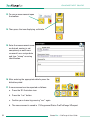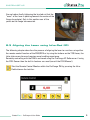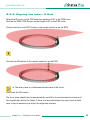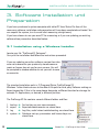
1
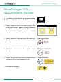
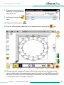
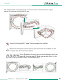
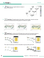
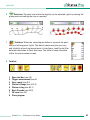
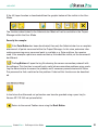
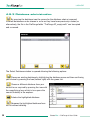
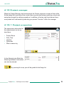
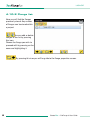
Software for Flange Measurement
User Guide
BA 1065 E 10/13
Another fine solution by
CONTENT
User Guide – English
Software
September 2012 – Software Version 3.1112.16.0
We would like to congratulate you on the purchase of your Status Pro Software. Before
initial usage you should carefully read the safety instructions as well as the user guidelines contained in this manual. We wish you every success when using this Measurement
Instrument.
Please note: User Manuals can be amended when improvements or changes to the product range have been carried out. Use the link below to make sure you have the most up
to date version of your User Manual:
www.statuspro.com/doc/Maschinengeometrie/Bedienungsanleitungen/BA_ProFlangeV3_1065_E.pdf
Content
PROFLANGE V3 – QUICKSTART GUIDE . . . . . . . . . . . . . . . . . . . . . . . . . . . . . . . . . . . . . . . . . . . . .4
1. SYSTEM COMPONENTS . . . . . . . . . . . . . . . . . . . . . . . . . . . . . . . . . . . . . . . . . . . . . . . . . . . . . . . .7
1.1 Laser source . . . . . . . . . . . . . . . . . . . . . . . . . . . . . . . . . . . . . . . . . . . . . . . . . . . . . . . . . . . . . . .7
1.2 Laser Receiver . . . . . . . . . . . . . . . . . . . . . . . . . . . . . . . . . . . . . . . . . . . . . . . . . . . . . . . . . . . . .7
2. SYSTEM SET-UP . . . . . . . . . . . . . . . . . . . . . . . . . . . . . . . . . . . . . . . . . . . . . . . . . . . . . . . . . . . . . . .8
2.1 Horizontal situation . . . . . . . . . . . . . . . . . . . . . . . . . . . . . . . . . . . . . . . . . . . . . . . . . . . . . . . . .8
2.2 Vertical or sloping flange situation . . . . . . . . . . . . . . . . . . . . . . . . . . . . . . . . . . . . . . . . . . . .8
2.3 Aligning the Laser using Infra-Red (IR) . . . . . . . . . . . . . . . . . . . . . . . . . . . . . . . . . . . . . . . .9
2.3.1 Aligning the laser: Y-Axis . . . . . . . . . . . . . . . . . . . . . . . . . . . . . . . . . . . . . . . . . . . . . . .10
2.3.2 Aligning the laser: X-Axis . . . . . . . . . . . . . . . . . . . . . . . . . . . . . . . . . . . . . . . . . . . . . .11
3. SOFTWARE INSTALLATION UND PREPARATION . . . . . . . . . . . . . . . . . . . . . . . . . . . . . . . . . .12
3.1 Installation using a Windows Installer . . . . . . . . . . . . . . . . . . . . . . . . . . . . . . . . . . . . . . . .12
3.2 Installation without a Windows Installer . . . . . . . . . . . . . . . . . . . . . . . . . . . . . . . . . . . . . .13
3.3 Connecting Sensors with the Software . . . . . . . . . . . . . . . . . . . . . . . . . . . . . . . . . . . . . . .13
3.3.1 Choice of sensor . . . . . . . . . . . . . . . . . . . . . . . . . . . . . . . . . . . . . . . . . . . . . . . . . . . . . .14
3.3.2 Sensor search . . . . . . . . . . . . . . . . . . . . . . . . . . . . . . . . . . . . . . . . . . . . . . . . . . . . . . . .14
3.3.3 License key . . . . . . . . . . . . . . . . . . . . . . . . . . . . . . . . . . . . . . . . . . . . . . . . . . . . . . . . . . .14
3.3.4 Connection status . . . . . . . . . . . . . . . . . . . . . . . . . . . . . . . . . . . . . . . . . . . . . . . . . . . . .15
2
Status Pro – ProFlange v3 User Guide
CONTENT
4. PROFLANGE V3 – USAGE . . . . . . . . . . . . . . . . . . . . . . . . . . . . . . . . . . . . . . . . . . . . . . . . . . . . . .16
4.1 Start dialogue . . . . . . . . . . . . . . . . . . . . . . . . . . . . . . . . . . . . . . . . . . . . . . . . . . . . . . . . . . . . .16
4.1.1 Open existing measurement – opens a previously stored measurement . . . . . .16
4.1.2 Start a new measurement – Initiate a new measurement . . . . . . . . . . . . . . . . . .17
4.2 Options bar . . . . . . . . . . . . . . . . . . . . . . . . . . . . . . . . . . . . . . . . . . . . . . . . . . . . . . . . . . . . . . .19
4.3 3D view . . . . . . . . . . . . . . . . . . . . . . . . . . . . . . . . . . . . . . . . . . . . . . . . . . . . . . . . . . . . . . . . . . .20
4.4 2D view . . . . . . . . . . . . . . . . . . . . . . . . . . . . . . . . . . . . . . . . . . . . . . . . . . . . . . . . . . . . . . . . . . .25
4.5 Taper . . . . . . . . . . . . . . . . . . . . . . . . . . . . . . . . . . . . . . . . . . . . . . . . . . . . . . . . . . . . . . . . . . . . .26
4.6 Short-Waviness . . . . . . . . . . . . . . . . . . . . . . . . . . . . . . . . . . . . . . . . . . . . . . . . . . . . . . . . . . .28
4.7 Data view . . . . . . . . . . . . . . . . . . . . . . . . . . . . . . . . . . . . . . . . . . . . . . . . . . . . . . . . . . . . . . . . .31
4.8 Tool bar . . . . . . . . . . . . . . . . . . . . . . . . . . . . . . . . . . . . . . . . . . . . . . . . . . . . . . . . . . . . . . . . . . .32
4.8.1 Open a measurement . . . . . . . . . . . . . . . . . . . . . . . . . . . . . . . . . . . . . . . . . . . . . . . . . .32
4.8.2 Storing a measurement . . . . . . . . . . . . . . . . . . . . . . . . . . . . . . . . . . . . . . . . . . . . . . . .33
4.9 Toolbox . . . . . . . . . . . . . . . . . . . . . . . . . . . . . . . . . . . . . . . . . . . . . . . . . . . . . . . . . . . . . . . . . . .34
4.9.1 User role . . . . . . . . . . . . . . . . . . . . . . . . . . . . . . . . . . . . . . . . . . . . . . . . . . . . . . . . . . . . .35
4.9.2 Advanced Set-up . . . . . . . . . . . . . . . . . . . . . . . . . . . . . . . . . . . . . . . . . . . . . . . . . . . . . .35
4.9.3 Database administration . . . . . . . . . . . . . . . . . . . . . . . . . . . . . . . . . . . . . . . . . . . . . . .38
4.10 Project manager . . . . . . . . . . . . . . . . . . . . . . . . . . . . . . . . . . . . . . . . . . . . . . . . . . . . . . . . . .39
4.10.1 Project properties . . . . . . . . . . . . . . . . . . . . . . . . . . . . . . . . . . . . . . . . . . . . . . . . . . . .39
4.10.2 Flange list . . . . . . . . . . . . . . . . . . . . . . . . . . . . . . . . . . . . . . . . . . . . . . . . . . . . . . . . . . .40
4.10.3 Flange properties . . . . . . . . . . . . . . . . . . . . . . . . . . . . . . . . . . . . . . . . . . . . . . . . . . . .41
4.10.4 Flange properties Page 2 (Administrator Mode) . . . . . . . . . . . . . . . . . . . . . . . . . .42
4.10.5 Ring list . . . . . . . . . . . . . . . . . . . . . . . . . . . . . . . . . . . . . . . . . . . . . . . . . . . . . . . . . . . . .42
4.10.6 Point list . . . . . . . . . . . . . . . . . . . . . . . . . . . . . . . . . . . . . . . . . . . . . . . . . . . . . . . . . . . .43
4.10.7 Short waviness classes . . . . . . . . . . . . . . . . . . . . . . . . . . . . . . . . . . . . . . . . . . . . . . .43
5. MEASUREMENT . . . . . . . . . . . . . . . . . . . . . . . . . . . . . . . . . . . . . . . . . . . . . . . . . . . . . . . . . . . . . .44
6. ANALYSIS . . . . . . . . . . . . . . . . . . . . . . . . . . . . . . . . . . . . . . . . . . . . . . . . . . . . . . . . . . . . . . . . . . .46
6.1 Setting points to zero, manually . . . . . . . . . . . . . . . . . . . . . . . . . . . . . . . . . . . . . . . . . . . . .46
6.2 Best-Fit Analysis . . . . . . . . . . . . . . . . . . . . . . . . . . . . . . . . . . . . . . . . . . . . . . . . . . . . . . . . . . .46
6.2.1 Ring select . . . . . . . . . . . . . . . . . . . . . . . . . . . . . . . . . . . . . . . . . . . . . . . . . . . . . . . . . . .47
6.2.2 Best-Fit Mode . . . . . . . . . . . . . . . . . . . . . . . . . . . . . . . . . . . . . . . . . . . . . . . . . . . . . . . .47
7. EXPORT AND REPORT . . . . . . . . . . . . . . . . . . . . . . . . . . . . . . . . . . . . . . . . . . . . . . . . . . . . . . . . .48
7.1.1 Export content . . . . . . . . . . . . . . . . . . . . . . . . . . . . . . . . . . . . . . . . . . . . . . . . . . . . . . . .49
7.1.2 Report Header / Corporate symbol . . . . . . . . . . . . . . . . . . . . . . . . . . . . . . . . . . . . . .49
7.2 Report . . . . . . . . . . . . . . . . . . . . . . . . . . . . . . . . . . . . . . . . . . . . . . . . . . . . . . . . . . . . . . . . . . . .50
8. ACCESSORIES AND FIXTURES . . . . . . . . . . . . . . . . . . . . . . . . . . . . . . . . . . . . . . . . . . . . . . . . .51
Status Pro – ProFlange v3 User Guide
3
QUICKSTART GUIDE
ProFlange V3 –
Quickstart Guide
1. Turn on the Display Unit and the Bluetooth Sensor.
2. Start the ProFlange software using the desktop icon.
3. Choose wether to start a new measurement (Start
a new measurement) or open a previous measurement (Open existing measurement). Our following
example will be a ”new measurements:
4. Specify amount of rings per flange (Ring count on
flange).
5. Specify the amount of points per ring (Point count
on ring).
6. Choose direction of measurement progress, either
clockwise (CW) or anti-clockwise (CCW).
7. Move to the next page.
4
Status Pro – ProFlange v3 User Guide
QUICKSTART GUIDE
8. Choose the appropriate ring
and enter the ring diameters.
(Ring diameter)
9. Confirm by pressing the
icon.
10. Choose the starting point.
11. Start the measurement procedure for the chosen point by pressing the
icon.
12. The measurement window will appear with the measurement value, as soon as the
value is stable, press the measurement icon on the display or on the R280 sensor. The
next point to be measured will be displayed automatically. The order of measurement
is 1 Outside, 1 Inside, 2 Outside, 2 Inside etc.
Status Pro – ProFlange v3 User Guide
5
QUICKSTART GUIDE
13. To save a measurement open
the toolbox.
14. Then press the icon displaying a diskette.
15. Enter the measurement name
as desired, naming is not
compulsory as each measurement has a unique date
and time “stamp“ ensuring
identification.
16. After entering the appropriate details press the
diskette symbol.
17. A measurement can be exported as follows:
a. Press the 3D illustration icon
b. Press the ”csv“ button
c. Confirm your choice by pressing ”csv“ again
d. The measurement is saved in C:\Programme\Status Pro\ProFlange V3\export
6
Status Pro – ProFlange v3 User Guide
SYSTEM COMPONENTS
1. System Components
1.1 Laser source
To carry out a flange measurement we utilise the T330 Sweep Laser from Status Pro:
T330 – Self-levelling Sweep Laser (BG 830203)
The T330 sweep laser delivers, in addition to the beam for
straightness, a laser plane perpendicular to the linear beam. This
laser plane enables flange measurements to be carried out,
using the self levelling properties of the T330 if needed. Ease of
use and flexibility are keywords when describing the T330,
making complex geometrical tasks a lot simpler.
1.2 Laser Receiver
For flange measurements there is a choice of two sensors:
R280 – Laser Receiver (BG 831500)
The R280 is a robust sensor for use with the rotating beam of
the T330. The R280 has a measurement range of 40 mm. The
measuring distance between T330 and R280 is up to 80 metres.
Communication between the R280, the T330 and Remote Control
(RC310) is over Infra-red, communication between R280 and
Display Unit (UMPC) is over Bluetooth. A button for triggering
a measurement remotely is also housed within the sensor, ensuring complete concentration on the measurement.
R310 – Laser Receiver (BG 830134)
The R310 is a robust sensor for use with the rotating beam of the
T330. The R310 has a measurement range of 80 mm. The measuring distance between T330 and R310 is up to 80 metres.
Communication between the R310, the T330 and Remote Control
(RC310) is over Infra-red. An LED display and a touchpad for the
menu make the R310 into a complete measurement equipment in
itself without the need for software or a PC. An optional Bluetooth
attachment is available for use with the UMPC and software.
Status Pro – ProFlange v3 User Guide
7
SYSTEM SET-UP
2. System Set-up
To measure the flatness of a flange we need a T330 Sweep Laser and either a R280 or an
R310 Laser Receiver. The laser plane is first aligned more or less parallel to the measurement surface, which can be horizontal, vertical or even sloping. The rotating laser beam
provides a virtual plane and the sensor simply measures the distance between the surface and the laser plane.
2.1 Horizontal situation
If the flange is positioned horizontally and has been
levelled then the set up is achieved very easily by activating the self-levelling function of the T330.
To do this, simply press the levelling button on the T330.
The T330 now adjusts both the X and the Y-axes parallel to the flange as in the horizontal plane both axes are
sensitive to gravity. The four LED´s surrounding the
laser aperture keep you informed of the levelling progress. When the LED´s are lit constantly green, then
the laser has completed the levelling process.
Nevertheless make a quick check using a sensor to
make sure the laser plane is parallel to the measurement surface.
2.2 Vertical or sloping flange situation
If the flange is not horizontally placed the T330 Laser may have to
be secured to the flange using the flange adapter BG 830580 and
one of the flange holes.
The laser is placed on the measurement side of the flange, the
long M8 screw is placed through a screw hole from the reverse
side of the flange and screwed into the M8 threaded hole in the
laser. The cone is moved up to the flange and then the knurled
clamping nut is tightened against the cone thus clamping the laser
to the flange.
8
Status Pro – ProFlange v3 User Guide
SYSTEM SET-UP
Ensure before finally tightening the knurled nut that the
“nose” of the laser is pointing towards the centre of the
flange (see photo). Only in this position can all the
points on the flange be measured.
2.3 Aligning the Laser using Infra-Red (IR)
The following chapter describes the process of aligning the laser to a surface using either
the remote control function of the R280/R310 or by using the buttons on the T330 Laser; the
latter takes more time and requires more handling experience.
Remotely controlling with the R280 is achieved using the ProFlange V3 Software or if using
the R310 Sensor then the built in features are used (consult the R310 Manual).
Start the Remote Control Monitor within the ProFlange SW by pressing the InfraRed button on the task bar.
Status Pro – ProFlange v3 User Guide
9
SYSTEM SET-UP
2.3.1 Aligning the laser: Y-Axis
Place the R280 / R310 nearest to the T330 on the flange.
Press the 0 button.
Open the IR mirror on the laser to around 45° and point it towards the opposite side of the
flange.
Place the R280 / R310 farthest away from the T330 on the opposite of the flange.
Choose and press the POS Y button in the remote control or on the R310.
Activate the IR function in the remote control or on the R310.
➜ The laser plane is pulled down towards zero in the y-axis.
Deactivate the IR function.
Check the zero position of the laser plane at the nearest and farthest points of the y-axis
again and if necessary repeat the process.
10
Status Pro – ProFlange v3 User Guide
SYSTEM SET-UP
2.3.2 Aligning the laser: X-Axis
Rotate the IR mirror on the T330 Laser to a position at 90° to the T330 Laser.
Position the R280 / R310 Sensor on the flange at 90° to the T330 Laser.
Choose and press the POS X button in the remote control or on the R310
Activate the IR function in the remote control or on the R310
➜ The laser plane is pulled down towards zero in the x-axis.
Deactivate the IR function.
The laser plane should now be approximately parallel to the measurement surface at all
four coordinates within the flange. If there are large deviations from zero in one or both
axes it may be necessary to repeat the alignment process.
Status Pro – ProFlange v3 User Guide
11
INSTALLATION AND PREPARATION
3. Software Installation und
Preparation
If you have purchased a system complete with tablet PC from Status Pro then all the
necessary software installation and preparation will have been completed and tested. You
can unpack the system, turn it on and start measuring straight away.
If you have chosen to use your own PC for measuring or if you are updating you existing
software then proceed as described below:
3.1 Installation using a Windows Installer
Locate your file ”ProFlangeV3_Setup.exe“.
Carry out the installation and follow the instructions presented.
If you are updating an earlier software version then take
care not to overwrite your previously stored measurements or license key set-ups for your sensors. You will
be prompted to choose whether or not you wish to save
or overwrite.
The standard installation path is: C:\Programs\Status Pro\ProFlange V3
Windows 7 often blocks access to the default file path for third party Software making an
Export impossible. If this is the case please designate a different location for storage, for
example C:\ Applications, or desired, a different partition.
The ProFlange V3 file contains several different folders and files:
1.
2.
3.
4.
12
backup
export
log
system
➜
➜
➜
➜
For backing up your measurements
Exported measurements are stored here
Log files, useful when troubleshooting, are stored here
Database set-ups, parameters and license keys are
stored here.
Status Pro – ProFlange v3 User Guide
INSTALLATION AND PREPARATION
A short cut (link) to the ProFlange Software will be placed on your desktop
during installation.
3.2 Installation without a Windows Installer
If you have received the software as a complete folder without the installer, then you can
freely choose where you store the program folder and place a short-cut on your desktop,
Windows 7 often blocks access to the default file path for third party Software making an
Export impossible. If this is the case please designate a different location for storage, for
example C:\ Applications, or desired, a different partition. It is also possible to run the software without installing, provision is that all the necessary files are complete. It is also
possible to copy the complete software folder onto other computers and to run the software locally when evaluating for example.
If you have only received a ProFlange.exe file for upgrading then replace the old with the
new file in the main folder thus keeping all stored information and licenses.
3.3 Connecting Sensors with the Software
If you have purchased a system complete with tablet PC from Status Pro then the sensors
will already be registered within the ProFlange software. If you have installed the software on your PC, after starting the software the sensor will not be registered, the sensor
symbol is greyed-out .
To register a sensor for the first time turn the sensor on and ensure Bluetooth is
turned on. Enter the toolbox by pressing the icon at the bottom left side of the user
screen, then confirm by pressing the toolbox icon again.
In the toolbox menu there is a magnifying glass icon at the bottom left corner of the
screen. When pressed the Device Manager is opened:
Status Pro – ProFlange v3 User Guide
13
INSTALLATION AND PREPARATION
3.3.1 Choice of sensor
When the “Select Device” screen is opened
press the icon at the bottom left hand side of
the screen.
A further window called ”Search for Devices“
will be opened.
3.3.2 Sensor search
In the ”Search for Devices“ window, the discovered com ports and Bluetooth devices will
be listed.
If several sensors are being showed then
choose your sensor and confirm by pressing
the OK button in the task bar. The sensor will
now be listed in the Select Device list.
All devices found within the ”Search for Devices“ will be listed under ”Select Devices“.
This enables speedy changes between different sensors (i.e. R280 and R310) if necessary.
Choose the desired sensor from the ”Select Devices“ list and confirm through
acknowledging the “tick“ icon.
3.3.3 License key
If a sensor is being registered in the software
for the time then you will be prompted to enter
a valid license key. The license key should
have been delivered with the software.
Enter the 16 digit code (with or without hyphen) an confirm by pressing OK.
If successful a green ”tick“ will appear, confirm by pressing the tick.
14
Status Pro – ProFlange v3 User Guide
INSTALLATION AND PREPARATION
When sensor and software communication has been established then
the sensor symbol in the top right hand corner of the measurement
screen will be coloured red and yellow.
3.3.4 Connection status
1)
2)
3)
1) Bluetooth in the UMPC is turned off , no sensors are connected with the software
➜ Check if Bluetooth is switched on or not, re-start the software.
2) Bluetooth is turned on but no sensors are connected with the software
➜ If you have not yet registered your sensor with the software, proceed from
chapter 3.3.
➜ Tap the greyed out sensor icon to initiate a short sensor search.
➜ If necessary, check the Bluetooth mode on the sensor (R310 BT).
3) Bluetooth is turned on and a sensor is available and connected.
Status Pro – ProFlange v3 User Guide
15
USAGE
4. ProFlange V3 – Usage
When ProFlange V3 is started the sensor is connected automatically. If the connection
fails follow the instruction in the Connecting Sensors link.
4.1 Start dialogue
Initially you have the choice between:
Open existing measurement
➜ opens a previously stored measurement
Start a new measurement
➜ initiates a new measurement / opens a template
4.1.1 Open existing measurement – opens a previously stored measurement
All relevant information for the flange; ring count, point count, diameter etc. can be stored
as a template without any measured points. This accelerates a measurement on site as all
the parameters are ready for recall when measuring. To do this, proceed as in the next
chapter.
The following pages describe how to make a template for regular use.
Information on how to find and open a template is described under chapter 4.8.1.
16
Status Pro – ProFlange v3 User Guide
USAGE
4.1.2 Start a new measurement – Initiate a new
measurement
To proceed, a certain amount of detail must be entered:
Page 1: New measurement > Flange properties
1
2
3
5
6
4
7
9
8
1 Project name: Choose a suitable name for the project or leave as the default
_Standard, all measurements would then be stored under _Standard.
2 Flange name: Allocate the flange to be measured a name for unique identification, it is
also possible to leave the default _Flange Nr 1.
3 Ring count on flange: Enter how many rings within a flange are to be measured.
4 Point count on each ring: Enter how many points are to be measured within the rings.
5 Flange orientation: Enter either (clockwise) or anti-clockwise (counter clockwise)
6 Tolerance / Longwaviness: you can enter one tolerance threshold, more than one
threshold by entering a value at _1 and/or _2, or no threshold using the N/V button.
7 Taper / Tilt Tolerance: Tolerance threshold for tilt and taper can also be chosen.
Negative Tilt is a tilt towards the flange centre.
8 Go to the next page
9 End entry (X). In this case the tick cannot be acknowledged as data is missing.
Status Pro – ProFlange v3 User Guide
17
USAGE
Page 2: New measurement > Ring properties
1
2
3
5
4
1
2
3
4
5
Ring name: Choose a ring from column 3 and give it a name or leave as the default.
Ring diameter: Enter the diameter of the chosen ring*.
Ringliste: Shows a list of rings to be measured counting down in diameter.
Back to page 1 (”Flange properties“).
Break off entry procedure (X).
Complete the information entry procedure (Tick).
After confirming your entries you will automatically move on to the 3D view where the
flange is depicted with the entered attributes. The measurement can be carried out immediately!
* When entering the ring diameters, enter the diameters at the points directly under the
sensor and not the physical inside and outside diameters of the flange.
18
Status Pro – ProFlange v3 User Guide
USAGE
4.2 Options bar
Using the button to the left of the Power Button
a menu bar will be opened:
3D view – 3D view of the flange. This is the main screen used when carrying out the
measurement.
2D view – 2D view of the flange ”opened out“ or ”unravelled“. You can analyse single
point reliability as well as the relationship a particular point and its neighbours.
Taper / Tilt view – When 2 or more rings have been measured then the tilt and taper
of the flange can be viewed when this button is pressed.
Short waviness view – The waviness classes can be viewed here providing they
were entered in the Project Manager.
Data view – Tabelled view of all of the measured points/values.
Export – Opens the Export Monitor, here you can export all the information relevant
to the measurement as a .pdf file or as a .csv file or simply pictograms as a bmp file.
Measurement monitor – delivers ”real time“ values from the sensor.
Remote control – opens the remote control feature enable control of the R280
sensor.
Abbruch – Closes the menu bar.
Status Pro – ProFlange v3 User Guide
19
USAGE
4.3 3D view
1
10
2
3
4
9
5
6
7
11
8
1 Info bar: Detailed information is shown here: flange number, rings, measurement
points, ring diameter and present point value.
By pressing the
button, additional information can be viewed.
2 View Control: Using this feature, you can change the view of the flange to meet your
preference. Some of the symbols have more than one function, in this case scroll
through to use the features.
Maximise view: Use this button to return to the full view of the flange if you have
been using the zoom feature.
3D mode: The globe signifies that the 3D view is active. When you move over the
screen with your finger the graphic is freely rotatable.
20
Status Pro – ProFlange v3 User Guide
USAGE
The example below shows the flange in a vertical then in a horizontal plane. Again,
choose the view most comfortable for you.
Freeze: By clicking the 3D ”globe“ display movement is disabled.
Movement: Clicking the crossed arrows again will enable up and down as well
as side to side movement of the display.
Views: By toggling the grids you can choose between view from
below (N), from the side (W), Birds eye view with Point 1 at the
top (Top), Birds eye view with Point 1 at the bottom (Top).
Status Pro – ProFlange v3 User Guide
21
USAGE
3
Zoom: Use the magnify feature to zoom in
and out as required.
4
Guidelines: Through toggling the guides, the zero plane, then the max/min
planes will be displayed, pressing again will remove all guides.
5
Labelling: By clicking the XYZ Symbol, the screen for the choice of labels is
opened. The measurement points are allocated with the desired information.
The size of the texting can also be adjusted using the green point shift.
22
Status Pro – ProFlange v3 User Guide
USAGE
6
Point size: The point size within the display can be adjusted, again by moving the
green point and setting the size as required.
7
Statistics: When the cake diagram button is pressed, the point
analysis table appears (right). The details concerning the accuracy
and reliability of each measured point is listed here, read Capital 6 for
detailed information to Point Accuracy. The table is freely moveable
within the measurement screen.
8 Task bar:
1
1
2
3
4
5
6
7
8
2
3
4
5
6
7
8
Open tool bar (see 4.8)
Trigger measurement (see 5.)
Zero a point (see 6.1)
Choice of flange (see 4.10.2)
Choice of ring (see 6.2.1)
Best-Fit mode (see 6.2.2)
3D view (see 4.2)
Close program
Status Pro – ProFlange v3 User Guide
23
USAGE
24
9
Scaling: Using this feature you can change the scale of the diagram being displayed, similar to a zoom feature.
10
Connection status: The upper symbol displays the Bluetooth availability of the
Display Unit or PC. The lower symbol displays whether or not the measurement
sensor is connected with the software. (see Chapter 3.3.4)
11
Battery status: The upper symbol shows the charge level of the sensor battery.
The lower symbol shows the charge level of the Display Unit or PC battery.
Status Pro – ProFlange v3 User Guide
USAGE
4.4 2D view
In the 2D view the flange is depicted as if it has been ”unravelled“ or opened out. A sinusoidal line is not unusual here as it is essentially a circle.
Graphics: All measured rings are displayed within the diagram and are displayed using
unique symbols. The parameter lines or guides are displayed as coloured lines, measurement points which are outside of these tolerances are clearly visible. The tolerance or
guidelines can blended in or out by toggle-clicking within the graphic window.
Information: By ”hovering“ the cursor over the measurement points within the diagram, a
grey column will appear and a desired point can be chosen by moving to the left or right.
The measurement information for the appropriate point is displayed in the lower table of
information.
Zoom: To zoom in within the diagram, simply move the cursor to the top left hand corner of
the diagram then click and hold the left mouse button, then drag the cursor towards the
bottom right hand corner. To zoom out, press and hold the left mouse button, then move
from bottom right towards top left within the diagram.
To maximise the diagram simply press the Max icon.
The statistics table will appear when the symbol is pressed (see 3D view).
The XYZ button reveals the labelling options (see 3D view).
Status Pro – ProFlange v3 User Guide
25
USAGE
4.5 Taper
In the Taper window, the inclination of the flange is expressed as Taper [mm] and Tilt
[mrad]. The gradient is calculated and shown for each measured point. The calculation is
as follows: Value of the inner ring point – (minus) value of the outer ring point, hence,
when the outer ring is lower than the inner ring we have a positive gradient and when the
outer ring is higher than the inner ring, we have a negative slope or gradient.
Graphic view: In the graphic view, the gradient of each and every point is shown as a bar
chart. Positive gradients are have a bar above the zero line and negative gradients are
below the zero line. If the value of the point is within the desired tolerances the bar is
coloured green, values outside the tolerances are either red or blue in colour.
The graphic always shows rings that are directly neighboured or next to each other, if
there are more than two rings, then the outside two rings are firstly illustrated, afterwards
the next ring in the inward direction and so on. The change between rings is achieved by
scrolling down within the Point table.
Analysis table: In the middle table the statistical values of the measurement or flange as a
whole are shown.
26
Status Pro – ProFlange v3 User Guide
USAGE
Result table: Choose a point by clicking on a bar within the diagram. The vertical grey bar
indicates the present position. All relevant information concerning the present point is
shown in the Points Table.
When scrolling down in the Points Table, the next rings in the inward direction are shown
successively. The last inner ring has no data concerning tilt or taper.
Zoom: Zoom in within the diagram, simply move the cursor to the top left hand corner of
the diagram then click and hold the left mouse button, then drag the cursor towards the
bottom right hand corner. To zoom out, press and hold the left mouse button, then move
from bottom right towards top left within the diagram
To return to the full view simply press the Max icon.
The statistics table will appear when this symbol is pressed (see 3D view).
The XYZ button reveals the labelling options (see 3D view).
Status Pro – ProFlange v3 User Guide
27
USAGE
4.6 Short-Waviness
The short waviness is a very useful tool for judging point to point detail and not only the
general waviness of the complete flange. To emphasize the significance of short-waviness, a flange can have a general waviness of 1 mm, but if this millimetre is the difference
between two or three neighboured point then there is probably a kerb in the flange.
The Short-waviness class can be chosen from the menu. Please read chapter 4.10.
Graphic chart: The short waviness for each point is shown in the diagram. The tolerances
are shown as coloured lines, in this case red. If the values are not within tolerances the
measured point will be shown in a colour other than green as entered in the menu.
Point results: In the middle table, the results can be viewed for the current point highlighted by the grey bar within the graphic chart.
Short waviness results: The short waviness of the flange can be viewed here, also dependant on which class or classes were chosen or desired. The statistical values are shown.
28
Status Pro – ProFlange v3 User Guide
USAGE
Zoom: To zoom in within the diagram, simply move the cursor to the top left hand corner of
the diagram then click and hold the left mouse button, then drag the cursor towards the
bottom right hand corner. To zoom out, press and hold the left mouse button, then move
from bottom right towards top left within the diagram.
To return to the full view simply press the Max icon.
The statistics table will appear when this symbol is pressed (see 3D view).
The XYZ button reveals the labelling options (see 3D view).
Calculation: The short waviness class for 2 points, for example, observes each and every
point within the flange, in direct relation to the points directly neighbouring, one to the left
and one to the right. A short waviness class for 3 points, for example, observes two points
to the left and two points to the right of each and every point on the flange.
Example of class 2 short-waviness (SW): The following diagram illustrates a measurement judged to Class 2 (Left, 2D view, right, short waviness view). Point 10 is viewed in
relation to points 9&11, Point 11 is viewed in relation to 10&12, Point 12 is viewed in relation to 11&13.
This shows for Point 11 (red area) two ”short-wavinesses“ (orange area):
Point 10 (-0,27) with Point 11 (-0,01) = 0,26 mm
Point 11 (-0,01) with Point 12 (+0,16) = 0,17 mm
The largest value shown is 0,26 and therefore the SW (Class2) value for Point 11.
Status Pro – ProFlange v3 User Guide
29
USAGE
Example of class 3 short waviness (SW): For the same measurement we will now “apply”
SW Class 3: Point 11 is compared to Point 9, Point 10, Point 12 und Point 13.
This shows for Point 11 (red area) three ”short-wavinesses“ (orange area):
Point 9 (-0,25), 10 (-0,27) and 11 (-0,01) = 0,26 mm
Point 10 (-0,27), 11 (-0,01) and 12 (+0,16) = 0,43 mm
Point 11 (-0,01), 12 (+0,16) and 13 (0,20) = 0,21 mm
The largest value shown is 0,43 mm and therefore the SW (Class3) value for Point.
30
Status Pro – ProFlange v3 User Guide
USAGE
4.7 Data view
The data view contains all the relevant data for the measurement and for analysis.
Point results: The results are sorted for Ring and Point respectively. Through clicking a
column header, the data can be sorted as wished, for example, sorting using the ”Z“
values.
The table delivers the following information for each measured point: Z or measurement
value, Taper, Tilt, Point Name, Angular position, Ring Diameter, Ring name, Measurement
reliability or quality, Date and time, Sensor temperature and Data Origin.
You can scroll through the measurement data either using the arrow buttons or by using
the touch screen with stylus or your fingers.
Analysis table: In the lowest table you will find the statistics for the measurement as a
whole:
•
•
•
•
•
Chosen Units and tolerances
Taper Max, Min, Absolute
Highest and lowest point (Peak to Peak)
Average and Standard Deviation
Median and RMS (Root mean square)
Status Pro – ProFlange v3 User Guide
31
USAGE
4.8 Tool bar
Using the tool symbol at the bottom left hand corner of the main screen
you open the tool bar containg the following options:
1 Project manager: Settings for the Project and Information concerning the
Rings, Flanges, Points, Tolerances as well as Analysis can be found here.
(see 4.10)
2 Empty page: Starts a new measurement. (see 4.1.2)
3 Open folder: Opens a stored measurement or template (see 4.8.1)
4 Save: Saves the current measurement, (opens save to disc dialogue).
5 Toolbox: Opens the toolbox for adjusting parameters etc.
6 Tool bar: Closes the tool bar.
4.8.1 Open a measurement
By pressing this icon you will 1
open the (stored) Measurements
screen enabling viewing or indeed 2
deleting of stored projects and
measurements as follows:
1 Closed files/projects: In block 1 3
there are three closed projects,
which can be opened by simply
pressing on the appropriate project.
4
5
6
Click again to close.
2 Project file opened: The opened file
shows the templates / measurements contained.
3 Measurement choice: Click the appropriate file to be opened.
4 Scrolling: Use the arrow buttons / icons to scroll through the screen entries.
5 Waste bin: The chosen file will be deleted.
6 Cancel / Open: Cancels or closes the dialogue (X) or opens the chosen measurement.
32
Status Pro – ProFlange v3 User Guide
USAGE
4.8.2 Storing a measurement
Using the diskette symbol you can save a measurement or template. By pressing the
icon, the Save Project screen will be opened:
Projekt name: The last saved project name will be suggested or you can choose a new
Project file name.
Measurement name: The name of the current measurement can be entered here.
Measured by: The name of the person who carried out the task can be entered here.
Memo: Any comments related to the measurement process before or during the measurement can be entered here.
The storing of the measurement will be carried out when the diskette symbol is
pressed.
Status Pro – ProFlange v3 User Guide
33
USAGE
4.9 Toolbox
In the Toolbox you can carry out adjustments concerning the measurement as follows:
1
2
3
4
5
6
10
1
2
3
4
5
6
7
8
9
10
11
12
13
14
34
9
8
7
11
12 13
14
System Unit: Choose the units of measurement.
Precision settings: Choose the displayed measurement precision / resolution.
Display averaging time: Choose the screen averaging time.
Measurement duration: Choose the duration of the a triggered measurement.
Tolerances: Direct link to the tolerances input in the project manager.
User Role: Choose normal or expert mode and advanced set-up (➜ 4.9.1)
Window Control: Maximize or minimize the measurement screen size.
Remote Control: Opens the remote control window for the R280. (➜ 2.3)
SW Version information: Opens the remote control window for the R280.
Toolbox: Return to the previous screen.
Log file: View the log file (Connection Protocol).
Seek: Search for new receivers. (➜ 3.3)
License: Enter the license key for a newly connected receiver. (➜ 3.3.3)
Database: Choose a different database (➜ 4.9.3)
Status Pro – ProFlange v3 User Guide
USAGE
4.9.1 User role
On-Site Mode:
This mode is set as a default. Only functions necessary for the measurement are visible,
enabling ease of use. Advanced set-up adjustments are not available. The range of available functions can be preset by the Administrator.
Administrator Mode:
In the administrator mode all functions are freely available and
visible. Advanced set-up capability as well as the setting-up of the
On-Site Mode is possible.
4.9.2 Advanced Set-up
Specialised setting up is possible here:
Fixed Ring distance: This
is the standard mode. If deactivated, the 3D display will be
shown with ”real-time“ scaling,
which means the rings within
the measurement could be displayed on top of each other.
Use only if needed.
Show short waviness tolerance: If this option has been chosen, the points within a
measurement will be analysed with respect to short-waviness to each other.
Status Pro – ProFlange v3 User Guide
35
USAGE
Measured points outside of the pre-determined tolerances will be displayed (coloured) as
determined:
Examples of long-waviness (left) and short-waviness (right) on the same flange:
Visible Functions
Here you can activate or de-activate the functions to be visible in the Onsite Mode.
Choose carefully to avoid confusing the person measuring, or indeed to control aspects of
the measurement.
The graphic below shows a complete menu bar with all functions available:
If the short-waviness evaluation is not activated, the graphic below will be visible.
36
Status Pro – ProFlange v3 User Guide
USAGE
If the tilt / taper function is deactivated then the graphic below will be visible in the User
Mode.
The functions deactivated in the Administrator Mode will not be available in the Project
Manager within the User Mode.
Security for example:
If the Point Button has been deactivated, then only the Administrator has a complete
overview of all points measured within the Project Manager. In this view, extensive information concerning every measured point is available, e.g. Date and time, the receiver
used. If for example a point was measured twice, this would be visible, as the time would
be different.
The Log Button will open the log file showing the sensor connection protocoll with
the software. This function is normally only useful when connection problems arise, enabling the Administrator to assess the problem and if necessary communicate with Status
Pro personnel to find a solution for the problem. If desired this function can be deactivated.
In the future the Advanced set-up function can be safe-guarded using a pass key (in
Version V3.1112.16.0 not yet available)
Return to the normal Toolbox view using the Back Button.
Status Pro – ProFlange v3 User Guide
37
USAGE
4.9.3 Database administration
By pressing the database icon the screen for the database choice is opened.
Different databases can be chosen in as far as they have been previously created, or
alternatively, the file in the ProFlange folder ”ProFlange V3_empty.mdb“ can be copied
and re-named.
The Select Database window is opened allowing the following options:
Choose an existing database by highlighting the database name and then confirming
your choice by pressing the Icon (bottom right) with the green tick.
Choose a different database from your
hard drive as required by pressing the icon with
the magnifying glass, which in turn opens the
search directory in the explorer.
Deletes the highlighted database.
Removes the highlighted database from
the list without deleting.
38
Status Pro – ProFlange v3 User Guide
USAGE
4.10 Project manager
When the Project Manager has been opened, the Project properties screen will be visible.
At the bottom left hand side of the screen there are now two buttons enabling a structured
navigation through the settings procedure. In addition, at the top right hand corner there
are symbols with red bordering indicating you present “location” within the manager.
4.10.1 Project properties
The appropriate information for
the measurement can be entered here:
•
•
•
•
•
Project Name
Date, Time
Location
Contractor
Who is measuring
In the Administrator Mode the
following additional information
can also be entered:
By pressing this icon, you will be guided to the flange list.
Status Pro – ProFlange v3 User Guide
39
USAGE
4.10.2 Flange list
Here you will find the flanges
previously stored. Any number
of flanges can be stored within
a project.
You can add or delete
flanges to the list by pressing
this icon.
Choose the flange you wish to
proceed with by pressing on the
name and highlighting it.
By pressing this icon you will be guide to the flange properties screen.
40
Status Pro – ProFlange v3 User Guide
USAGE
4.10.3 Flange properties
Here you can view and/or edit
all information concerning the
flange measurement:
•
•
•
•
•
Flange Name
Points per Ring
Direction of measurement
Long-waviness
tolerances (±)
Taper / Tilt Tolerances
The colour for each tolerance condition can be
freely chosen by clicking the colour box next to
the appropriate tolerance. A colour dialogue
opens, and then by adjusting the RGB slide controllers the desired colour can be chosen.
In the Administrator mode, the flange extreme diameters can also be
entered, but only for documentation purposes
By pressing this icon you will be guided to the ”Ring list“.
By pressing this icon you will be guided to the ”Short waviness classes“.
Status Pro – ProFlange v3 User Guide
41
USAGE
4.10.4 Flange properties Page 2 (Administrator
Mode)
In the Administrator
mode, pressing this button, it
will take you to a second Flange
properties page where you add
more details (see right).
By pressing this
icon you will be guided to the
”Ring list“.
4.10.5 Ring list
The Ring list shows details of
the rings that have been already
entered.
Each ring can be chosen separately and its properties viewed
and if need be, edited. The rings
are sorted with the greatest diameter to the top.
You can add or delete
flanges to the list by pressing
this icon.
By pressing this
icon, you will be guided to the ”Point list“.
42
Status Pro – ProFlange v3 User Guide
USAGE
4.10.6 Point list
All relevant details regarding
each measured point can be
viewed here.
You can name the points as
desired and see when the point
was measured and with which
sensor.
4.10.7 Short
waviness classes
The choice of short-waviness class can be chosen from
the flange properties page by
pressing this icon.
You can view or change the
class of waviness here.
Using these icons you
can add or remove short-waviness classes.
When a waviness class is added, the next higher class is automatically chosen.
You can change the tolerances for the classes at will and allocate colours as desired (see
flange properties).
Status Pro – ProFlange v3 User Guide
43
MEASUREMENT
5. Measurement
When you start a new measurement or open an existing one, the start screen is always a
3D view of the measurement or template.
When this icon is visible, you can ”turn“ the flange to the desired perspective.
This icon indicates a fixed (frozen) view and is obtained by pressing the
icon.
Choose the ”start“ point.
Start the measurement procedure.
After initiating the measurement procedure, the measurement monitor with value appears,
as soon as the value is stable, press the measurement button within the monitor, or press
the measurement button on the R280 to trigger and record a measurement. After the measurement has been recorded, the next point to be measured will be selected automatically.
44
Status Pro – ProFlange v3 User Guide
MEASUREMENT
The measurement order is; 1 outer – 1 inner, 2 outer – 2 inner – 3 outer, etc. ...
When there are more than two rings the order is always from the outer to the next inner
point and the to the next outer point.
An existing point can be deleted by pressing the N/V button within the monitor.
The measurement screen can be maximized by carrying out a ”double-click“ on the measurement value within the monitor. This can be useful when measuring alone, as the
UMPC can be left alone and you only need to carry the sensor with you; the values are
visible from a distance, and the measurement is triggered using the R280.
In the maximized monitor, the following information is at hand:
•
•
•
•
•
Ring Number
Point Number
Ring name, if applicable
Point name, if applicable
Current measurement value (Z value)
”Double-clicking“ the measurement value again minimizes the monitor.
After completing a measurement, it is advisable to store the data quickly (see
chapter 4.8.2).
Status Pro – ProFlange v3 User Guide
45
ANALYSIS
6. Analysis
There are different ”tools“ for choice when analysing the data, usually only one criterion
or method is chosen.
6.1 Setting points to zero, manually
In some cases it may be defined ,which points are to be zeroed. In this case, using
the Zero button, you can freely choose which point or points are to be set to zero. If only
one point is chosen, then the whole scatter plot is raised or lowered accordingly. When
three points are chosen the plane will be defined over the three zeroed points.
6.2 Best-Fit Analysis
By pressing the icon you can access the Best-fit settings. When a best fit mode is
chosen the measured points are analyzed, an ideal plane is laid through all the points so
that the distance between each and every point, with respect to the plane, is minimized.
This is, as it were the zero-plane through all points.
46
Status Pro – ProFlange v3 User Guide
ANALYSIS
6.2.1 Ring select
In the main view the rings at hand are listed. By clicking on the rings you can choose
which and how many of the rings are to be included for the Best-Fit analysis. In this example, Ring 1 was chosen and Ring 2 was deactivated.
In such cases, when a tilted ring or a taper is required (one ring lower or higher than the
other) it does not make sense to include both rings in the calculation, as the Best-Fit analysis or plane would be placed through both rings. This would “cancel-out” taper and tilt.
6.2.2 Best-Fit Mode
This is the default and the most commonly used mode. With this mode the
plane is placed through all measured points and is very useful for the analysis of pure
waviness.
The 3-lowest-points Mode calculates the plane using the three lowest
points of the ring or flange and setting them to zero. This is the plane on which the ring or
flange would lie if placed on, as the three lowest points are set to zero.
The 3-highest points Mode calculates the plane using the three highest
points and setting them to zero. In this case the zero plane would lie above or on top of the
flange or ring.
Status Pro – ProFlange v3 User Guide
47
EXPORT AND REPORT
7. Export and Report
By pressing the CSV icon you can access the reporting and exporting view:
The File-path is set to the Export File of the measurement software as a default. This is
normally: C:\Programme\Status Pro\ProFlange V3.
Use the folder icon to designate a different file path or destination file for the export
task. If a pen drive/USB is connected, you can save directly to the drive or export the
whole database to the drive.
When the destination has been chosen, the CSV icon is pressed to carry out the task.
48
Status Pro – ProFlange v3 User Guide
EXPORT AND REPORT
7.1.1 Export content
The current measurement will be saved along with any zeroing or compensation chosen,
as well as the chosen zoom factor.
Additionally, the CSV (comma separated values) file for further evaluation in MS Excel will
be exported as well as the graphics in bitmap form. A full Report in PDF format completes
the export “package“.
7.1.2 Report Header / Corporate symbol
A corporate symbol can be included into the Report. To do this click on the Status Pro logo
then go to the graphic file you wish to be displayed. The chosen symbol will be displayed
centrally and should be 745 x 144 pixels in size. If the symbol is larger than 745 x 144 pixels,
the edges will be ”trimmed-down“ equally. Smaller symbols will be displayed centrally.
Status Pro – ProFlange v3 User Guide
49
EXPORT AND REPORT
7.2 Report
The exported measurement report contains all relevant information:
•
•
•
•
•
•
•
•
•
•
50
Report header as desired
Measurement name
Who carried out the measurement
Laser / Receiver Serial Number
Date / Time of measurement
Comments as required
Graphics of X and Y
Statistical information
Analysis method (i.e. Best-Fit)
Complete table of measurement
data
Status Pro – ProFlange v3 User Guide
ACCESSORIES
8. Accessories and fixtures
T330
Sweep Laser (BG 830203)
T330 Self-levelling Sweep Laser provides the basis or reference
for the majority of geometrical applications. The second component within the system will be one or more sensors measuring the beam position. The Self-levelling capability coupled
with intuitive ease of use are key features within our measurement system. Whether you are measuring Levelness, Flatness,
Straightness or even more complex tasks, the Status Pro
Measurement System provides a reliable yet easy to use solution for your problem.
R280
Laser Receiver (BG 831500)
The R280 essentially measures the distance between the work
surface and the laser beam. The T330 laser provides a near to
360° laser plane with a Sensor “reachability” of around 80 m.
Bluetooth communication with the PC and a changeable Li-Ion
rechargeable cell giving 8 Hrs measurement time.
Meas. range:
Resolution:
Status Pro – ProFlange v3 User Guide
40 mm
0.01 mm
51
ACCESSORIES
R310 II
Laser Receiver (BG 830134)
The R310 essentially measures the distance between the work
surface and the laser beam. The T330 laser provides a near to
360° laser plane. Sensor “reachability” of around 80 m The sensor has a keypad giving complete access to all features without
the need for a PC. Real-time measurement values over the LED
Display If required, Bluetooth communication with a PC is possible using a combined BT/ Battery pack
Meas. range:
80 mm
Resolution:
0.01 mm
Battery pack exchangeable as required:
With Bluetooth
BG 830135
Without Bluetooth
BG 830136
DU 320 Display Unit with touchscreen (IT 200410)
Rugged Touchscreen PC mit rubber protectors and a display
shield. Internal and external Battery packs with “hot-swap”
capability. Data transfer either over Bluetooth or USB/Pen
drive. Perfect for on-site use.
52
Status Pro – ProFlange v3 User Guide
ACCESSORIES
Tripods for Laser and Sensors (FIX STATIV-01-P … FIX STATIV-04-P)
Tripod 01-P:
Adj. height 545 mm – 935 mm, Weight 5,5 kg
Tripod 1.5-P:
Adj. height 760 mm – 1700 mm, Weight 12 kg
Tripod 02-P:
Adj. height 870 mm – 1900 mm, Weight 12 kg
Tripod 03-P:
Adj. height 1160 mm – 2520 mm, Weight 13 kg
Tripod 04-P:
Adj. height 1880 mm – 3910 mm, Weight 19 kg
SP ProFlange 10 – Starter Package for Flange Flatness
•
•
•
•
•
T330 Self-levelling Sweep Laser
Laser Receiver R280 with Battery and Charger
Laser Case with foam inlays: IP 65
ProFlange v3 with license key for R280
Accessories
Status Pro – ProFlange v3 User Guide
53
ACCESSORIES
SP ProFlange 20 – Starter Package with IT for Flange Flatness
•
•
•
•
•
•
T330 Self-levelling Sweep Laser
Laser Receiver R280 with Battery and Charger
Display Unit / UMPC DU320 with touchscreen
Laser Case with foam inlays: IP 65
ProFlange v3 Software with license key for R280
Accessories
SP ProFlange 30 – Professional Package with IT for Flange Flatness
and Parallelism
•
•
•
•
•
•
•
•
54
T330 Self-levelling Sweep Laser
Laser Receiver R310
Laser Receiver R545
Display Unit / UMPC DU320 with Touchscreen
RC310 Remote Control for T330 or R310
Laser case, large, IP 65
ProFlange v2 Software with license key for R310
Accessories
Status Pro – ProFlange v3 User Guide
MEMOS
Memos
Status Pro – ProFlange v3 User Guide
55
Status Pro Maschinenmesstechnik GmbH
Mausegatt 19
D-44866 Bochum
Phone: + 49 (0) 2327 - 9881 - 0
Fax: + 49 (0) 2327 - 9881 - 81
www.statuspro.com
[email protected]
Distributor
BA 1065E 10/13 · Design / DTP: Seichter & Steffens Grafikdesign, D-44229 Dortmund, Germany
Copyright 2013 Status Pro Maschinenmesstechnik GmbH. This brochure or parts thereof may not be copied or reproduced in
any other way without prior approval by Status Pro GmbH. Technical correctness and completeness remain reserved and
may be subject to changes without prior information. Information about mistakes this brochure may contain will be welcome
at any time.