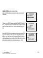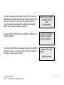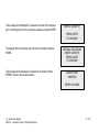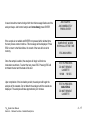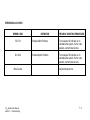
1
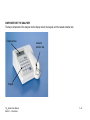
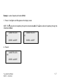
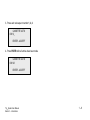
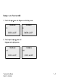
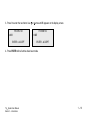
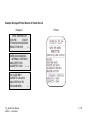
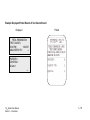
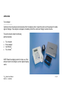
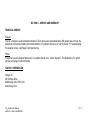
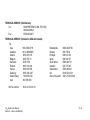
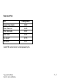
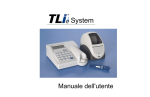
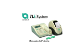
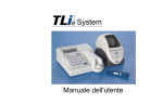
System User Manual IMPORTANT: Read the entire manual before operating the TLiIQ® System. Hologic UK Link 10 Napier Way Crawley, West Sussex RH10 9RA UK +44 (0) 1293 522 080 Hologic Inc. 250 Campus Drive Marlborough, MA 01752 USA TEL: For Technical Support (USA and Canada) 1-888-PRETERM (1-888-773-8376) 1-800-442-9892 FAX: 1-508-263-2967 TEL: For Technical Support (Outside the USA and Canada) Asia Australia: Austria: Belgium: Denmark: Finland: France: Germany: Ireland (Rep): Italy: +852 3526 0718 +61 2 9888 8000 0800 291 919 0800 773 78 8088 1378 0800 114 829 0800 913 659 0800 183 0227 1 800 554 144 800 786 308 Netherlands: Norway: Portugal: Spain: South Africa: Sweden: Switzerland: UK: Rest of the world: Intl Fax number: 0800 022 6782 800 155 64 800 841 034 900 994 197 0800 980 731 020 797 943 0800 298 921 0800 032 3318 0041.21.633.39.26 0041.21.633.39.10 2013 Hologic Inc. All rights reserved. No part of this publication may be reproduced, stored in a retrieval system, or transmitted, in any form or by any means in whole or in part without the prior written permission of Hologic Inc. The TLiIQ System is covered by U.S. patent numbers 6,267,722 and 6,394,952. The TLiIQ Analyzer is covered by U.S. patent number Des. 434,153. The Cassette Housing is covered by U.S. patent number Des. 432,244. The Hologic logo, TLiIQ, and TLiIQ QCette are registered trademarks of Hologic Inc. Printed in the USA i 06023-001 Rev 001 If this equipment is used in a manner not specified by the manufacturer, then the protection provided by the equipment may be impaired. FCC Notice: This equipment has been tested and found to comply with the limits of a Class B digital device, pursuant to Part 15 of the FCC Rules. These limits are designed to provide reasonable protection against harmful interference in a residential installation. This equipment generates, uses and can radiate radio frequency energy and, if not installed and used in accordance with the instructions, may cause harmful interference to radio communications. However, there is no guarantee that interference will not occur in a particular installation. If this equipment does cause harmful interference to radio or television reception, which can be determined by turning the equipment off and on, the user is encouraged to try to correct the interference by one or more of the following measures: Reorient or relocate the receiving antenna. Increase the separation between the equipment and receiver. Connect the equipment into an outlet on a circuit different from that to which the receiver is connected. Consult the dealer or an experienced radio/television technician for help. FCC Warning: Changes or modification not expressly approved by the manufacturer responsible for compliance could void the user's authority to operate the equipment. Note: The use of a non-shielded interface cable with this equipment is prohibited. TLiIQ System User Manual ii CE Notice: This equipment has been tested and found to be in compliance with the following standards per the IVD Directive: EN61326-1 EN55011 EN61010-1 EN61000-3-2 EN61000-3-3 EN61000-4-2 EN61000-4-4 EN61000-4-5 EN61000-4-6 EN61000-4-11 Electrical Equipment for Measurement, Control and Laboratory Use Radiated and Conducted Emissions Safety Requirements Harmonic Emissions Voltage Fluctuations Electrostatic Discharge Electrical Fast Transients Voltage Surges Conducted Immunity Voltage Interrupts TLiIQ System User Manual iii Disposal of Electrical & Electronic Equipment Waste Electrical and Electronic Equipment (WEEE) Hologic is dedicated to meeting country specific requirements associated with the environmentally sound treatment of our products. Our objective is to reduce the waste arising from our electrical and electronic equipment. Hologic realizes the benefits of subjecting such WEEE equipment to potential reuse, treatment, recycling or recovery to minimize the amount of hazardous substances entering the environment. Your Responsibility As a Hologic customer, you are responsible for ensuring that devices marked with the symbol shown below are not placed into the municipal waste system unless authorized to do so by the authorities in your area. Please contact Hologic (see below) prior to disposing any electrical equipment provided by Hologic. Symbol Used on the Instrument The following symbol is used on this instrument: Do not dispose in municipal waste. Contact Hologic (see below) for information regarding proper disposal. Reclamation Hologic will provide for the collection and proper reclamation of electrical devices we provide to our customers. Hologic strives to reuse Hologic devices, subassemblies, and components whenever possible. When reuse is not appropriate, Hologic will ensure the waste material is properly disposed of. TLiIQ System User Manual iv Hologic Contact Information Corporate Headquarters Authorized Representative - Europe TLiIQ System User Manual HOLOGIC INC. 250 CAMPUS DRIVE MARLBOROUGH, MA 01752 USA TEL: (USA and Canada) 1-888-PRETERM (1-888-773-8376) 1-800-442-9892 FAX: 1-508-263-2967 HOLOGIC (UK) LIMITED UNIT 2, LINK 10 NAPIER WAY CRAWLEY, WEST SUSSEX RH10 9RA UNITED KINGDOM Tel: +44 1293 522080 FAX: +44 1293 528010 v Symbols Used on the Instrument The following symbols are used on this instrument: TLiIQ System User Manual Warning, refer to accompanying documents. Manufactured by Waste Electrical and Electronic Equipment - contact Hologic for disposal of the instrument. Authorized Representative in the European Community Lot Store between 18°C and 30°C Catalog number For in vitro diagnostic testing vi TABLE OF CONTENTS Section I Introduction • Intended Use • General Description • Components of the Analyzer • Keypad • Keypad Functions • Keypad Entries • Cassette Insertion Site • Displayed/Printed Results • Specifications • Cautions and Warnings 2 Page 1-1 1-1 1-2 1-3 1-3 1-6 1-11 1-12 1-17 1-19 Installation • General • Environmental Factors • Unpacking • System Setup TLiIQ System User Manual Table of Contents 2-1 2-1 2-2 2-4 vii Section • • • • 3 4 Page 2-5 2-6 2-7 2-8 Getting Started Setting the Date and Time TLiIQ QCette® Setup Factory Default Settings General Operating/Testing Instructions • Starting the System • Set Calibration • Test Patient • Daily QC • Liquid Controls • Viewing Results On-Screen • Incubation Mode • Internal Mode • External Mode 3.1 3-2 3-4 3-7 3-9 3-12 3-13 3-13 3-14 Software Functions – Detailed Descriptions • Startup Screen • Main Menu 4-1 4-2 TLiIQ System User Manual Table of Contents viii Section • • • • • • • • 5 Page 4-3 4-5 4-10 4-14 4-19 4-19 4-21 4-23 4-24 4-24 4-27 4-28 4-29 4-33 Set Calibration Test Patient Daily QC Liquid Controls Access Data • View/Print Data • Data Transfer View Setup Change Setup • Date/Time • Autoprint • Incubation Mode • TLiIQ QCette® Setup Test Counts Care of the Analyzer • General Cleaning • Cleaning of Cassette Insertion Site • Cleaning Agents Approved for Use TLiIQ System User Manual Table of Contents 5-1 5-1 5-1 ix Section 6 Printer • Loading Printer Labels • Removing an Empty Label Roll • Clearing Label Jams 7 8 Page 6-1 6-4 6-5 Troubleshooting • General Information • Troubleshooting Table • Error/Invalid Codes 7-1 7-1 7-7 Service and Warranty • Technical Service • Contact Information - Technical Service • Replacement Parts • Contact Information - fFN Customer Service • Warranty 8-1 8-1 8-2 8-2 8-3 TLiIQ System User Manual Table of Contents x SECTION I – INTRODUCTION For In Vitro Diagnostic Use Only To be used by trained laboratory personnel INTENDED USE ® The Hologic TLiIQ System is intended to be used in conjunction with the Rapid fFN Cassette, the Rapid fFN Control Kit, ® and the TLiIQ QCette for the detection of fetal fibronectin in cervicovaginal secretions. Refer to the directional insert for the Rapid fFN Cassette for detailed intended use information. GENERAL DESCRIPTION ® The TLiIQ Analyzer is an electronic optical reflectance device that converts a colorimetric reaction from a cassette into a digitized format. The data are analyzed using multiple parameters, including a comparison of sample data to calibration data. The analyzer provides one of three possible patient test results: Positive, Negative, or Invalid. The result is positive if the signal intensity derived from the patient sample is greater than or equal to the reference calibration value specified by the calibration code. The result is negative if the signal intensity derived from the patient sample is less than the reference calibration value specified by the calibration code. The result is reported as invalid if specific internal test criteria have not been met. TLiIQ System User Manual Section 1 – Introduction 1–1 COMPONENTS OF THE ANALYZER The major components of the analyzer are the display screen, the keypad, and the cassette insertion site. Display screen Cassette insertion site Keypad TLiIQ System User Manual Section 1 – Introduction 1–2 KEYPAD Numeric – Use keypad to enter numerical characters from 0 to 9. Alpha – Use keypad to enter alpha characters from A to Z. KEYPAD FUNCTIONS (Vertical Scroll) Alpha characters - Use ↑ ↓ to navigate through the alphanumeric keys when selecting an alpha character. Scrolling through Data Records - Use ↑ ↓ when scrolling through data records in ACCESS DATA mode. Menu Screens - Some menus require up to three screens to display all of the options. Use ↑ ↓ to go to the next or previous screen of the menu. TLiIQ System User Manual Section 1 – Introduction 1–3 (Left Arrow Key) Previous Page - Use ← to go to the previous page within a data record. Delete - Use DELETE to delete characters to the left of the cursor. (Right Arrow Key) Next Page - Use → to go to the next page within a data record. Space - Use SPACE to enter a space in the position of the cursor. TLiIQ System User Manual Section 1 – Introduction 1–4 (Print/Enter Key) Accept/Confirm - Press ENTER to accept or confirm an entry in any data entry field. Print - Press PRINT to print a data record. This print function is only active when a data record is on the display screen. (Escape Key) Press ESC to return to the most recent Menu screen, unless otherwise specified. If ESC is pressed in any screen requiring data entry, all entries will revert to the previous setting. TLiIQ System User Manual Section 1 – Introduction 1–5 KEYPAD ENTRIES Entries of numerical characters require pressing the appropriate numeric key. Entries of alpha characters require pressing the numeric key containing the alpha character and the ↑ or ↓ arrows (scroll keys). TLiIQ System User Manual Section 1 – Introduction 1–6 Example - to enter Cassette Lot Number C9123. 1 - Press 2. Use ↑ arrow until C appears on the display screen. NOTE: The ↑ arrow will scroll repetitively through the characters 2-A-B-C. The ↓ arrow will scroll repetitively through the characters 2-C-B-A. CASSETTE LOT # >2 CASSETTE LOT # >C ENTER - ACCEPT ENTER - ACCEPT 2 - Press 9. CASSETTE LOT # >C9 ENTER - ACCEPT TLiIQ System User Manual Section 1 – Introduction 1–7 3 - Press each subsequent number 1, 2, 3. CASSETTE LOT # >C912_ ENTER - ACCEPT 4 - Press ENTER after all entries have been made. CASSETTE LOT # >C9123 ENTER - ACCEPT TLiIQ System User Manual Section 1 – Introduction 1–8 Example - to enter Patient Name ABE 1 - Press 2. Use ↑ or ↓ arrow until A appears on the display screen. PATIENT ID >2 PATIENT ID >A ENTER - ACCEPT ENTER - ACCEPT 2 - Press 2 again. Use ↑ or ↓ arrow until B appears on the display screen. PATIENT ID >A2 PATIENT ID >AB ENTER - ACCEPT TLiIQ System User Manual Section 1 – Introduction ENTER - ACCEPT 1–9 3 - Press 3 to enter the next letter. Use ↑ or ↓ arrow until E appears on the display screen. PATIENT ID >AB3 ENTER - ACCEPT PATIENT ID >ABE ENTER - ACCEPT 4 - Press ENTER after all entries have been made. TLiIQ System User Manual Section 1 – Introduction 1 – 10 CASSETTE INSERTION SITE The Cassette Insertion Site contains a slightly concave trough designed to capture any fluids that may have been spilled while applying sample to the Rapid fFN Cassette. This area of the instrument should be cleaned regularly (see Section 5). TLiIQ System User Manual Section 1 – Introduction 1 – 11 DISPLAYED/PRINTED RESULTS Each test result is displayed on the analyzer display screen. A test result requires three screens to display all of the data associated with the result. With AUTOPRINT ON, the test result is automatically printed. Each printed result requires one printer label. Results can be printed from any data record screen either immediately after a test or in DATA ACCESS mode. Example: Displayed/Printed Results of Calibration Record Displayed Printed FETAL FIBRONECTIN 02:10 PM 10/26/07 SYSTEM CALIBRATED USER:XXXXXXXXXXXX→ CAL CODE:FG56 CASSETTE LN:L1002 ANALYZER ID:01701 ESC-MAIN MENU ← TLiIQ System User Manual Section 1 – Introduction 1 – 12 ® Example: Displayed/Printed Results of TLiIQ QCette Displayed Printed QCette 02:40 PM 10/26/07 SYSTEM: PASS USER:XXXXXXXXXXXX → CAL CODE:FG56 QCette SN:004640 ANALYZER ID:01701 ESC-MAIN MENU TLiIQ System User Manual Section 1 – Introduction ← 1 – 13 Example: Displayed/Printed Results of Negative Control Record Displayed Printed FETAL FIBRONECTIN 02:45 PM 10/26/07 NEG CTL:M1023 RESULT:PASS → INTERNAL CONTROLS USER:XXXXXXXXXXXXXX ANALYZER: PASS CASSETTE: PASS ←→ CAL CODE:FG56 CASSETTE LN:L1002 ANALYZER ID:01701 ESC-MAIN MENU TLiIQ System User Manual Section 1 – Introduction ← 1 – 14 Example: Displayed/Printed Results of Patient Record Displayed Printed FETAL FIBRONECTIN 03:02 PM 10/26/07 PT:XXXXXXXXXXXXXXXX RESULT:POSITIVE → USER:XXXXXXXXXXXX INTERNAL CONTROLS ANALYZER: PASS CASSETTE: PASS ←→ CAL CODE:BB11 CASSETTE LN:A2222 ANALYZER ID:01701 ESC-MAIN MENU TLiIQ System User Manual Section 1 – Introduction ← 1 – 15 Example: Displayed/Printed Results of Test Counts Record Displayed Printed FETAL FIBRONECTIN TEST COUNTS 03:03 PM 10/26/07 ANALYZER:01701 → PATIENT:4 CONTROL:1 QCette:1 ← TLiIQ System User Manual Section 1 – Introduction 1 – 16 SPECIFICATIONS Power Supply UL 12 VDC listed power supply Memory Capacity 50 Calibration Records 50 QCette Records 50 Control Records 50 Patient Records Display 4 lines 20 characters per line alphanumeric 5 x 8 matrix Supertwist LCD Black characters with gray background Keypad 3.5 x 4.5 inches tactile membrane alphanumeric keys TLiIQ System User Manual Section 1 – Introduction 1 – 17 Dimensions Length - 8.9 inches Width - 6.9 inches Height - 1.0 to 3.0 inches Weight - 1.2 pounds Operating Temperature 18° to 30°C 64° to 86°F A.C. Supply 120VAC / 60Hz / 16W or 220VAC / 50Hz / 16W Input Connector Coaxial power plug with positive center conductor Output Connectors 9 pin male and 9 pin female data connectors TLiIQ System User Manual Section 1 – Introduction 1 – 18 CAUTIONS AND WARNINGS There are no known hazards associated with the TLiIQ System when it is operated in accordance with the instructions in this manual. However, you should be aware of situations that can result in serious injury. WARNING! Ensure that the analyzer power adapter is connected to a grounded AC electrical outlet that provides voltage and current specified by Hologic. Use of an incompatible power receptacle can cause shock and fire hazard. CAUTION! Use only the power adapter supplied by Hologic. Use of an incompatible power adapter can damage the internal components. CAUTION! Always turn off the power and unplug the power adapter before cleaning the exterior of the analyzer. Fluid can damage internal components. DO NOT clean the power adapter. CAUTION! Extreme heat can damage the display and other electronic components. TLiIQ System User Manual Section 1 – Introduction 1 – 19 WARNING! Never apply cleaning reagents by spray as the liquid may leak into the analyzer causing damage to the electrical components or possibly electrical shock to the user. CAUTION! Do not immerse the analyzer in liquid. Fluid can damage internal components. CAUTION! Do not clean the keypad with undiluted bleach solution or other solvents. Caustic cleaning solutions can damage the keypad. CAUTION! Use appropriate laboratory procedures for handling biohazardous materials. TLiIQ System User Manual Section 1 – Introduction 1 – 20 SECTION 2 – INSTALLATION GENERAL This section provides detailed installation instructions for the TLiIQ System. Follow installation steps carefully to insure proper installation and operation. ENVIRONMENTAL FACTORS The TLiIQ System has been designed to be safe under the following conditions: Indoor use; Altitudes up to 2000m; Maximum relative humidity of 80% for temperatures up to 31°C decreasing linearly to 50% relative humidity at 40°C; Main supply voltage fluctuations not to exceed ± 10% of the nominal; transient overvoltages according to Installation Category and Pollution Degree 2. However, as with all electronic instruments, prolonged exposure to high temperature and humidity should be avoided. The operating temperature should be held relatively constant. The optimum operating temperature is 18° to 30°C (64° to 86°F). Before operating, allow the instrument to equilibrate to room temperature. Place the instrument where it will not be subjected to extreme temperature variations (e.g., near open windows, ovens, hot plates, radiators, direct sunlight). TLiIQ System User Manual Section 2 – Installation 2–1 UNPACKING TLiIQ Analyzer _______________________ Carefully remove the analyzer and accessories from the shipping carton. Inspect the carton and the analyzer for visible signs of damage. If the analyzer is damaged, immediately contact the carrier and Hologic Customer Service. The carton should contain the following parts/accessories: • • • • TLiIQ Analyzer Power Adapter User Manual ® TLiIQ QCette NOTE: Retain the shipping carton for future use. If the analyzer needs to be shipped, use the original shipping carton. TLiIQ System User Manual Section 2 – Installation 2–2 Printer Carefully remove the printer and accessories from the shipping carton. Inspect the carton and the printer for visible signs of damage. If the printer is damaged, immediately contact the carrier and Hologic Customer Service. The printer carton should contain the following parts/accessories: • • • • Printer Printer Labels (2 rolls) Power Cord Printer Cable NOTE: Retain the shipping carton for future use. If the printer needs to be shipped, use the original shipping carton. TLiIQ System User Manual Section 2 – Installation 2–3 SYSTEM SETUP 1. The Analyzer and Printer should be placed on a flat, level surface. 2. Connect the 9-pin connector of the printer cable to the analyzer and the modular jack to the printer. System Printer Analyzer 3. Connect the small connector of the analyzer power adapter to the analyzer and the larger power connector to a grounded AC electrical outlet. Caution: Only power connectors provided with the TLiIQ analyzer and printer may be used. Any substitutions can result in damage to the TLiIQ analyzer and printer. 4. Connect the small connector of the printer power cord to the printer and the larger connector of the power cord to a grounded AC electrical outlet. TLiIQ System User Manual Section 2 – Installation 2–4 GETTING STARTED Turn the analyzer power switch to the ON position. The power switch is located on the left side of the instrument. (If the analyzer does not turn on, see Section 6, Troubleshooting.) The analyzer will perform SYSTEM DIAGNOSTICS (a self-test of the analyzer components). If there is a problem after the self-test, a beep will sound to indicate an error and an error code will be displayed. If an error code is displayed, refer to the troubleshooting section of the manual. HOLOGIC TLi SYSTEM VERSION 2.0 SYSTEM DIAGNOSTICS IN PROCESS HOLOGIC TLi SYSTEM VERSION 2.0 03:00 PM 10/26/07 Once SYSTEM DIAGNOSTICS is complete, the display will change to the software VERSION, DATE, and TIME for five seconds, and then to the fFN Main Menu. The date and time may need to be reset for your time zone. TLiIQ System User Manual Section 2 – Installation 2–5 SETTING THE DATE AND TIME 1. From the Main Menu, select CHANGE SETUP by pressing the ↓ to get to the second page of the Main Menu. Press 6 for CHANGE SETUP. This will display the SETUP MENU. 2. From the SETUP MENU, press 1 to display DATE/TIME and follow the prompts. fFN MAIN MENU 4-ACCESS DATA 5-VIEW SETUP 6-CHANGE SETUP ↑↓ SETUP MENU 1-DATE/TIME 2-AUTOPRINT 3-INCUBATION MODE ↓ For more details about setting the date and time, see Section 4, Software Functions – Detailed Descriptions. TLiIQ System User Manual Section 2 – Installation 2–6 ® TLiIQ QCette SETUP 1. From the Main Menu, select CHANGE SETUP by pressing the ↓ to get to the second page of the Main Menu. Press 6 for CHANGE SETUP. This will display the SETUP MENU. 2. From the SETUP MENU, press the ↓ or 4 to display QCette SETUP and follow the prompts. fFN MAIN MENU 4-ACCESS DATA 5-VIEW SETUP 6-CHANGE SETUP ↑↓ SETUP MENU 1-DATE/TIME 2-AUTOPRINT 3-INCUBATION MODE ↓ SETUP MENU 4-QCette SETUP ↑ For more details about setting up the TLiIQ QCette, see Section 4, Software Functions – Detailed Descriptions. TLiIQ System User Manual Section 2 – Installation 2–7 FACTORY DEFAULT SETTINGS The TLiIQ System uses the following default settings. To customize the unit to your laboratory requirements, refer to Section 4, Software Functions – Detailed Descriptions. The Default Settings are as follows: AUTOPRINT Factory setting is Autoprint ON. After every result, the printer will generate a printed result. INCUBATION MODE Factory setting is INTERNAL Mode. The incubation mode refers to the timing of the incubation process and the initiation of the cassette analysis. In the INTERNAL mode, the analyzer will time the incubation and automatically start the analysis when the incubation is complete. In the EXTERNAL mode, the user will be responsible for timing the incubation and for starting the analysis. NOTE: The INTERNAL mode is recommended by the manufacturer to ensure proper timing of the assay. TLiIQ System User Manual Section 2 – Installation 2–8 SECTION 3 – GENERAL OPERATING / TESTING INSTRUCTIONS After instrument installation, the TLiIQ analyzer can be operated on a day-to-day basis by using the following procedures. Read Section 4 for detailed descriptions of displays, prompts and operating sequences. STARTING THE SYSTEM 1. Turn on the analyzer using the on/off switch located on the left side of the analyzer. The screen will display SYSTEM DIAGNOSTICS. If the analyzer fails the self-test, two beeps will sound; otherwise the analyzer will go to the next screen. Once SYSTEM DIAGNOSTICS is complete, the display will change to the software VERSION and the DATE and TIME for five seconds and then to the Main Menu. Verify the date and time are correct. See Section 4 for setting Date/Time. HOLOGIC TLi SYSTEM VERSION 2.0 SYSTEM DIAGNOSTICS IN PROCESS HOLOGIC TLi SYSTEM VERSION 2.0 03:00 PM 10/26/07 2. Turn on the printer using switch at rear and ensure labels are in the printer. See Section 6 for loading printer labels. TLiIQ System User Manual Section 3 – General Operating/Testing Instructions 3−1 SET CALIBRATION NOTE: Calibration must be set when changing cassette lots. 1. From the Main Menu, press 2 to select SET CALIBRATION. 2. Enter USER ID and press ENTER. 3. Enter the CASSETTE LOT# (on cassette pouch) and press ENTER. The lot number must be entered to proceed to the next step. TLiIQ System User Manual Section 3 – General Operating/Testing Instructions fFN MAIN MENU 1-TEST PATIENT 2-SET CALIBRATION 3-DAILY QC ↓ SET CALIBRATION USER ID >JOHN SMITH ENTER-CONFIRM SET CALIBRATION CASSETTE LOT# >L1002 ENTER-ACCEPT 3−2 4. Enter the CALIBRATION CODE# (on cassette box label) and press ENTER. The code number must be entered to proceed to the next step. NOTE: The calibration code is established by Hologic for each lot of Rapid fFN Cassettes. 5. When calibration is complete, the system will automatically display and print the result if AUTOPRINT is set to ON, or it may be printed/reprinted by pressing the PRINT/ENTER key. SET CALIBRATION CALIBRATION CODE# >FG56 ENTER-ACCEPT FETAL FIBRONECTIN 03:00 PM 10/26/07 SYSTEM CALIBRATED USER:JOHN SMITH → 6. Press ESC to return to the Main Menu. TLiIQ System User Manual Section 3 – General Operating/Testing Instructions 3−3 TEST PATIENT (Internal Incubation Mode) 1. From the Main Menu, press 1 to select TEST PATIENT. 2. Enter USER ID and press ENTER. 3. Enter the last two digits of the CASSETTE LOT# (on cassette pouch) and press ENTER. The lot number must be entered to proceed to the next step. NOTE: The analyzer will automatically compare the CASSETTE LOT# used to set calibration with the cassette lot number used for patient testing. If the lot numbers do not match, the analyzer will request the user to recalibrate the system. The cassette lot number used for calibration will be displayed on the third line. TLiIQ System User Manual Section 3 – General Operating/Testing Instructions fFN MAIN MENU 1-TEST PATIENT 2-SET CALIBRATION 3-DAILY QC ↓ TEST PATIENT USER ID >JOHN SMITH ENTER-CONFIRM TEST PATIENT CASSETTE LOT# >L1002 ENTER-ACCEPT 3−4 4. Enter up to 16 alphanumeric characters for a PATIENT ID and press ENTER. PATIENT ID >JANE DOE 123 ENTER-ACCEPT 5. Insert cassette and press ENTER. 6. Add sample and immediately press ENTER. TLiIQ System User Manual Section 3 – General Operating/Testing Instructions INTERNAL INCUBATION INSERT CASSETTE PRESS ENTER TO CONTINUE ADD SAMPLE AND IMMEDIATELY PRESS ENTER 3−5 7. The analyzer will begin a 20-minute incubation countdown. 8. Following incubation, the analyzer will begin analysis of the cassette. 9. When testing is complete, the system will automatically display and print the result if AUTOPRINT is set to ON, or it may be printed/reprinted by pressing the PRINT/ENTER key. TEST IN PROCESS DO NOT REMOVE CASSETTE 19 MIN 56 SEC TEST IN PROCESS ANALYZING DO NOT REMOVE CASSETTE FETAL FIBRONECTIN 03:00 PM 10/26/07 PT:JANE DOE 123 RESULT:POSITIVE → 10. Press ESC to return to the Main Menu. TLiIQ System User Manual Section 3 – General Operating/Testing Instructions 3−6 DAILY QC NOTE: TLiIQ QCette SETUP must be performed PRIOR to running the QCette as a quality control device. See Section 4 for TLiIQ QCette SETUP. 1. From the Main Menu, press 3 to select DAILY QC. fFN MAIN MENU 1-TEST PATIENT 2-SET CALIBRATION 3-DAILY QC ↓ 2. Enter USER ID and press ENTER. QCette USER ID >JOHN SMITH ENTER-CONFIRM 3. Enter the QCette SN (on QCette plastic housing) and press ENTER. The serial number must be entered to proceed to the next step. The correct format is 6 numbers (e.g., 001004). Enter all leading zeros. QCette ENTER QCette SN >001004 ENTER-ACCEPT NOTE: The serial number entered at daily QC must be identical to the serial number entered at TLiIQ QCette setup. TLiIQ System User Manual Section 3 – General Operating/Testing Instructions 3−7 4. Insert the QCette and press ENTER. The analyzer will begin the analysis of the QCette. INSERT QCette ENTER-CONTINUE TEST IN PROCESS ANALYZING DO NOT REMOVE CASSETTE 5. When testing is complete, the system will automatically display and print the result if AUTOPRINT is set to ON, or it may be printed/reprinted by pressing the PRINT/ENTER key. 6. Press ESC to return to the Main Menu. TLiIQ System User Manual Section 3 – General Operating/Testing Instructions QCette 03:00 PM 10/26/07 SYSTEM: PASS USER:JOHN SMITH → 3−8 LIQUID CONTROLS (Internal Incubation Mode) 1. From the Main Menu, press 8 to select LIQUID CONTROLS. fFN MAIN MENU 7-TEST COUNTS 8-LIQUID CONTROLS ↓ 2. Enter USER ID and press ENTER. 3. Enter the CASSETTE LOT# (on cassette pouch) and press ENTER. The lot number must be entered to proceed to the next step. TLiIQ System User Manual Section 3 – General Operating/Testing Instructions RUN CONTROL USER ID >JOHN SMITH ENTER-CONFIRM RUN CONTROL CASSETTE LOT# >L1002 ENTER-ACCEPT 3−9 4. Select Negative or Positive Control. CONTROL TEST MENU 1-NEGATIVE CONTROL 2-POSITIVE CONTROL 5. Enter the CONTROL LOT# (on bottle label) and press ENTER. NEGATIVE CTL LOT# >M1023 ENTER-CONFIRM 6. Insert cassette and press ENTER. TLiIQ System User Manual Section 3 – General Operating/Testing Instructions INTERNAL INCUBATION INSERT CASSETTE PRESS ENTER TO CONTINUE 3 − 10 7. Add sample and immediately press ENTER. ADD SAMPLE AND IMMEDIATELY PRESS ENTER 8. The analyzer will begin a 20-minute incubation countdown. TEST IN PROCESS DO NOT REMOVE CASSETTE 19 MIN 56 SEC 9. Following incubation, the analyzer will begin analysis of the cassette. TEST IN PROCESS ANALYZING DO NOT REMOVE CASSETTE 10. When testing is complete, the system will automatically display and print the result if AUTOPRINT is set to ON, or it may be printed/reprinted by pressing the PRINT/ENTER key. 11. Press ESC to return to the Main Menu. TLiIQ System User Manual Section 3 – General Operating/Testing Instructions FETAL FIBRONECTIN 03:00 PM 10/26/07 NEG CTL:M1023 RESULT:PASS → 3 − 11 VIEWING RESULTS ON SCREEN Upon completion of every test, the analyzer will automatically display the results on up to three screens. Each screen can be accessed by using the ← and → keys. To print the result record, press the ENTER/PRINT key from any screen. FETAL FIBRONECTIN 03:00 PM 10/26/07 PT:JANE DOE 123 RESULT:POSITIVE → NOTE: Internal controls are performed automatically during each Rapid fFN test. These internal controls check for (1) a threshold level of signal at the procedural control line, (2) proper sample flow across the Rapid fFN Cassette, (3) absence of conjugate aggregation, and (4) proper functioning of the TLiIQ analyzer hardware. INTERNAL CONTROLS USER:JOHN SMITH ANALYZER: PASS CASSETTE: PASS ←→ CAL CODE:FG56 CASSETTE LN:L1002 ANALYZER ID:00426 ESC-MAIN MENU TLiIQ System User Manual Section 3 – General Operating/Testing Instructions 3 − 12 ← INCUBATION MODE The incubation mode may be Internal (incubation timed by analyzer) or External (incubation timed by user). The user prompts are the same for both modes until the analyzer reaches the “INSERT CASSETTE” screen. NOTE: The INTERNAL mode is recommended by the manufacturer to ensure proper timing of the assay. INTERNAL MODE – In this mode, pressing ENTER will prompt the user to add the sample and the analyzer will automatically complete the test. If the sample is not added within 2 minutes, the test is invalidated. INTERNAL INCUBATION INSERT CASSETTE PRESS ENTER TO CONTINUE ADD SAMPLE AND IMMEDIATELY PRESS ENTER TEST IN PROCESS DO NOT REMOVE CASSETTE 19 MIN 56 SEC TLiIQ System User Manual Section 3 – General Operating/Testing Instructions 3 − 13 EXTERNAL MODE – In this mode, the user is responsible for timing the incubation and starting the analysis. Upon completion of 20 minute incubation, insert cassette and press ENTER. The analyzer will automatically complete the test. If additional cassettes are run, wait at least 5 minutes before adding sample to the next cassette. EXTERNAL INCUBATION WHEN TIME COMPLETE INSERT CASSETTE AND PRESS ENTER TEST IN PROCESS ANALYZING DO NOT REMOVE CASSETTE TLiIQ System User Manual Section 3 – General Operating/Testing Instructions 3 − 14 SECTION 4 − SOFTWARE FUNCTIONS - DETAILED DESCRIPTIONS STARTUP SCREEN When the analyzer is turned on, the screen will display HOLOGIC TLi SYSTEM and the software version, while performing an internal self-test (SYSTEM DIAGNOSTICS). Following the self-test, the analyzer displays the software version and the current date and time for five seconds before displaying the Main Menu. HOLOGIC TLi SYSTEM VERSION 2.0 SYSTEM DIAGNOSTICS IN PROCESS HOLOGIC TLi SYSTEM VERSION 2.0 03:00 PM TLiIQ System User Manual Section 4 − Software Functions - Detailed Descriptions 10/26/07 4−1 MAIN MENU The Main Menu, displayed over three screens, consists of Test Patient, Set Calibration, Daily QC, Access Data, View Setup, Change Setup, Test Counts, and Liquid Controls. Selecting the number in front of each option initiates that procedure or displays a submenu. fFN MAIN MENU 1-TEST PATIENT 2-SET CALIBRATION 3-DAILY QC ↓ fFN MAIN MENU 4-ACCESS DATA 5-VIEW SETUP 6-CHANGE SETUP ↑↓ fFN MAIN MENU 7-TEST COUNTS 8-LIQUID CONTROLS ↑ TLiIQ System User Manual Section 4 − Software Functions - Detailed Descriptions 4−2 SET CALIBRATION Option 2 on the Main Menu screen allows the user to set the calibration on the analyzer. Follow the analyzer prompts. Calibration must be set when changing cassette lots. NOTE: If the calibration has not been set, menu option 2 will flash. Calibration must be set before the analyzer can be used for testing. The most recent USER ID is always displayed. Press ENTER to accept the ID, or enter a new User ID. This field will accept 15 alpha or numeric characters. To leave this field blank, delete the information using the ← key. TLiIQ System User Manual Section 4 − Software Functions - Detailed Descriptions fFN MAIN MENU 1-TEST PATIENT 2-SET CALIBRATION 3-DAILY QC ↓ SET CALIBRATION USER ID >JOHN SMITH ENTER-CONFIRM 4−3 The CASSETTE LOT# must be entered to proceed to the next step. The CASSETTE LOT# is located on the cassette pouch. The software requires that the lot number is entered in the correct format: one alpha character followed by four numeric characters (e.g., L1002). The CALIBRATION CODE# must be entered to proceed to the next step. The CALIBRATION CODE# is located on the cassette box. The software requires that the code number is entered in the correct format: two alpha characters followed by two numeric characters (e.g., FG56). NOTE: The calibration code is established by Hologic for each lot of Rapid fFN Cassettes. Calibration Data Record - This record is displayed over two screens. Each screen can be accessed by using the → and ← keys. The complete record will be printed automatically if AUTOPRINT is set to ON, or it may be printed/reprinted by pressing the PRINT/ENTER key. SET CALIBRATION CASSETTE LOT# >L1002 ENTER-ACCEPT SET CALIBRATION CALIBRATION CODE# >FG56 ENTER-ACCEPT FETAL FIBRONECTIN 03:00 PM 10/26/07 SYSTEM CALIBRATED USER:JOHN SMITH → CAL CODE:FG56 CASSETTE LN:L1002 ANALYZER ID:00426 ESC-MAIN MENU TLiIQ System User Manual Section 4 − Software Functions - Detailed Descriptions ← 4−4 TEST PATIENT (Internal Incubation Mode) Option 1 on the Main Menu screen allows the user to test a patient sample. Follow the analyzer prompts. The most recent USER ID is always displayed. Press ENTER to accept the ID, or enter a new User ID. This field will accept 15 alpha or numeric characters. To leave this field blank, delete the information using the ← key. The CASSETTE LOT# must be entered to proceed to the next step. For convenience, the last 2 numbers only can be entered if the lot has not changed. The CASSETTE LOT# is located on the cassette pouch. The software requires that the lot number is entered in the correct format: one alpha character followed by four numeric characters (e.g., L1002). TLiIQ System User Manual Section 4 − Software Functions - Detailed Descriptions fFN MAIN MENU 1-TEST PATIENT 2-SET CALIBRATION 3-DAILY QC ↓ TEST PATIENT USER ID >JOHN SMITH ENTER-CONFIRM TEST PATIENT CASSETTE LOT# >L1002 ENTER-ACCEPT 4−5 The analyzer automatically compares the CASSETTE LOT# used to set calibration with the cassette lot number used for patient testing. If the lot numbers do not match, the test process cannot continue. When this occurs, the cassette lot number used for calibration will be displayed, and the user is prompted to recalibrate the system. CASSETTE LOT CHANGED CALIBRATE SYSTEM L1002 ESC-MAIN MENU Enter up to 16 alphanumeric characters for a PATIENT ID and press ENTER. PATIENT ID >JANE DOE 123 ENTER-ACCEPT This message will be displayed if a cassette is present in the analyzer prior to reaching the next screen. Remove cassette and press ENTER. REMOVE CASSETTE PRESS ENTER TO CONTINUE TLiIQ System User Manual Section 4 − Software Functions - Detailed Descriptions 4−6 The analyzer then prompts the user to insert cassette and press ENTER. This message will be displayed if a cassette is not inserted. Press ENTER to return to the previous screen. INTERNAL INCUBATION INSERT CASSETTE PRESS ENTER TO CONTINUE CASSETTE CASSETT NOT NOT INSERTED ENTER-CONTINUE A two-minute timer starts during which time this message flashes and the analyzer beeps. Add patient sample and immediately press ENTER. TLiIQ System User Manual Section 4 − Software Functions - Detailed Descriptions ADD SAMPLE AND IMMEDIATELY PRESS ENTER 4−7 If the patient sample is not added and ENTER not pressed within allotted time, the test process cannot continue. This message will be displayed. Press ESC to return to the Main Menu. No record of the test will be held in memory. Once the sample is added, the analyzer will begin a 20-minute incubation countdown. To abort the test, press ESC. Pressing ESC will terminate the test and the data will be lost. Upon completion of the incubation period, the analyzer will begin the analysis of the cassette. Do not disturb the analyzer until the results are displayed. The analysis will take approximately 2 - 3 minutes. TLiIQ System User Manual Section 4 − Software Functions - Detailed Descriptions SAMPLE NOT ADDED WITHIN ALLOTTED TIME ESC-MAIN MENU TEST IN PROCESS DO NOT REMOVE CASSETTE 19 MIN 56 SEC TEST IN PROCESS ANALYZING DO NOT REMOVE CASSETTE 4−8 TEST WARNING: This message will be displayed if ESC was pressed during testing. Lines 1 and 2 will flash prompting the user to select ENTER to continue test, or ESC to end test. This message will hold for 5 seconds and then revert back to its respective screen. If the test is cancelled, a new cassette will be required to repeat the test. ARE YOU SURE YOU WANT TO CANCEL TEST ENTER-CONTINUE ESC-MAIN MENU Patient Data Record – This record is displayed over three screens. Each screen can be accessed by using the ← and → keys. The complete record will be printed automatically if AUTOPRINT is set to ON, or it may be printed/reprinted by pressing the PRINT/ENTER key. FETAL FIBRONECTIN 03:00 PM 10/26/07 PT:JANE DOE 123 RESULT:POSITIVE → Patient results are POSITIVE, NEGATIVE, or INVALID. An INVALID result should be repeated. (See Section 7, Item 13.) Invalid results will not be stored in memory. NOTE: Internal Controls are performed automatically during each Rapid fFN test. These internal controls check for (1) a threshold level of signal at the procedural control line, (2) proper sample flow across the Rapid fFN Cassette, (3) absence of conjugate aggregation, and (4) proper functioning of the TLiIQ analyzer hardware. TLiIQ System User Manual Section 4 − Software Functions - Detailed Descriptions INTERNAL CONTROLS USER:JOHN SMITH ANALYZER: PASS CASSETTE: PASS ←→ CAL CODE:FG56 CASSETTE LN:L1002 ANALYZER ID:00426 ESC-MAIN MENU ← 4−9 DAILY QC ® Prior to running the TLiIQ QCette for the first time, QCette SETUP must be performed. See page 4-29. Refer to the TLiIQ QCette directional insert for more information. Option 3 on the Main Menu screen allows the user to run the QCette. The most recent USER ID is always displayed. Press ENTER to accept the ID, or enter a new User ID. This field will accept 15 alpha or numeric characters. To leave this field blank, delete the information using the ← key. The QCette SN must be entered to proceed to the next step. The serial number is printed on the QCette plastic housing. The software requires that the serial number is entered in the correct format: six numeric characters (e.g., 001004). Enter all leading zeros. TLiIQ System User Manual Section 4 − Software Functions - Detailed Descriptions fFN MAIN MENU 1-TEST PATIENT 2-SET CALIBRATION 3-DAILY QC ↓ QCette USER ID >JOHN SMITH ENTER-CONFIRM QCette ENTER QCette SN >001004 ENTER-CONFIRM 4 − 10 This message will be displayed if the QCette serial number entered is not identical to the serial number entered at the time of QCette setup. This message will be displayed if a cassette is present in the analyzer prior to reaching the next screen. Remove cassette and press ENTER. CASSETTE # CHANGED NNNNNN SETUP ANALYZER CTL ESC-MAIN MENU REMOVE CASSETTE PRESS ENTER TO CONTINUE The analyzer then prompts the user to insert the QCette and press ENTER. INSERT QCette ENTER-CONTINUE This message will be displayed if the QCette is not inserted. Press ENTER to continue. CASSETTE NOT INSERTED ENTER-CONTINUE TLiIQ System User Manual Section 4 − Software Functions - Detailed Descriptions 4 − 11 A two-minute timer starts during which time this message flashes and the analyzer beeps. Insert the QCette and press ENTER. INSERT QCette ENTER-CONTINUE The analyzer will read the QCette. Do not disturb the analyzer until the results are displayed. The analysis will take approximately 2-3 minutes. TLiIQ System User Manual Section 4 − Software Functions - Detailed Descriptions TEST IN PROCESS ANALYZING DO NOT REMOVE CASSETTE 4 − 12 TEST WARNING: This message will be displayed if ESC was pressed during testing. Lines 1 and 2 will flash prompting the user to select ENTER to continue test, or ESC to end test. This message will hold for 5 seconds and then revert back to its respective screen. QCette Data Record – This record will be displayed on two screens. Each screen can be accessed by using the ← and → keys. The complete record will be printed automatically if AUTOPRINT is set to ON, or it may be printed/reprinted by pressing the PRINT/ENTER key. ARE YOU SURE YOU WANT TO CANCEL TEST ENTER-CONTINUE ESC-MAIN MENU QCette 03:00 PM 10/26/07 SYSTEM: PASS USER:JOHN SMITH → QCette results are SYSTEM PASS, SYSTEM FAIL, or INVALID. A FAIL or INVALID result should be repeated. (See Section 7, Items 9 and 10.) Invalid results will not be stored in memory. TLiIQ System User Manual Section 4 − Software Functions - Detailed Descriptions CAL CODE:FG56 QCette SN:00104 ANALYZER ID:00426 ESC-MAIN MENU ← 4 − 13 LIQUID CONTROLS (Internal Incubation Mode) Option 8 on the Main Menu screen allows the user to run the LIQUID CONTROLS. fFN MAIN MENU 7-TEST COUNTS 8-LIQUID CONTROLS ↓ The most recent USER ID is always displayed. Press ENTER to accept the ID, or enter a new User ID. This field will accept 15 alpha or numeric characters. To leave this field blank, delete the information using the ← key. The CASSETTE LOT# must be entered to proceed to the next step. For convenience, the last 2 numbers only can be entered if the lot has not changed. The CASSETTE LOT# is located on the cassette pouch. The software requires that the lot number is entered in the correct format: one alpha character followed by four numeric characters (e.g., L1002). TLiIQ System User Manual Section 4 − Software Functions - Detailed Descriptions RUN CONTROL USER ID >JOHN SMITH ENTER-CONFIRM RUN CONTROL CASSETTE LOT# >L1002 ENTER - ACCEPT 4 − 14 The analyzer automatically compares the CASSETTE LOT# used to set calibration with the cassette lot number used for testing controls. If the lot numbers do not match, the test process cannot continue. When this occurs, the cassette lot number used for calibration will be displayed, and the user is prompted to recalibrate the system. CASSETTE LOT CHANGED CALIBRATE SYSTEM L1002 ESC-MAIN MENU From the CONTROL TEST MENU, select 1-NEGATIVE CONTROL or 2POSITIVE CONTROL. CONTROL TEST MENU 1-NEGATIVE CONTROL 2-POSITIVE CONTROL The most recent CONTROL LOT# is always displayed. Press ENTER to accept the lot number, or enter a new control lot number. This field will accept up to 12 alphanumeric characters. NEGATIVE CTL LOT# >M1023 ENTER-CONFIRM TLiIQ System User Manual Section 4 − Software Functions - Detailed Descriptions 4 − 15 This message will be displayed if a cassette is present in the analyzer prior to reaching the next screen. Remove cassette and press ENTER. REMOVE CASSETTE PRESS ENTER TO CONTINUE The analyzer then prompts the user to insert the cassette and press ENTER. This message will be displayed if a cassette is not inserted. Press ENTER to return to the previous screen. INTERNAL INCUBATION INSERT CASSETTE PRESS ENTER TO CONTINUE CASSETTE NOT INSERTED ENTER-CONTINUE TLiIQ System User Manual Section 4 − Software Functions - Detailed Descriptions 4 − 16 A two-minute timer starts during which time this message flashes and the analyzer beeps. Add control sample and immediately press ENTER. ADD SAMPLE AND IMMEDIATELY PRESS ENTER If the sample is not added and ENTER not pressed within allotted time, the test process cannot continue. This message will be displayed. Press ESC to return to the Main Menu. No record of the test will be held in memory. SAMPLE NOT ADDED WITHIN ALLOTTED TIME Once the sample is added, the analyzer will begin a 20-minute incubation countdown. To abort the test, press ESC. Pressing ESC will terminate the test and the data will be lost. Upon completion of the incubation period, the analyzer will begin the analysis of the cassette. Do not disturb the analyzer until the results are displayed. The analysis will take approximately 2-3 minutes. TLiIQ System User Manual Section 4 − Software Functions - Detailed Descriptions ESC-MAIN MENU TEST IN PROCESS DO NOT REMOVE CASSETTE 19 MIN 56 SEC TEST IN PROCESS ANALYZING DO NOT REMOVE CASSETTE 4 − 17 TEST WARNING: This message will be displayed if ESC was pressed during testing. Lines 1 and 2 will flash prompting the user to select ENTER to continue test or ESC to end test. This message will hold for 5 seconds and then revert back to its respective screen. If the test is cancelled, a new cassette will be required to repeat the test. ARE YOU SURE YOU WANT TO CANCEL TEST ENTER–CONTINUE ESC–MAIN MENU Liquid Control Data Record - This record is displayed over three screens. Each screen can be accessed by using the ← and → keys. The complete record will be printed automatically if AUTOPRINT is set to ON, or it may be printed/reprinted by pressing the PRINT/ENTER key. FETAL FIBRONECTIN 03:00 PM 10/26/07 NEG CTL:M1023 RESULT:PASS → Control results are PASS, FAIL, or INVALID. A FAIL or INVALID result should be repeated (See Section 7, Items 11 and 12.) INTERNAL CONTROLS USER:JOHN SMITH ANALYZER: PASS CASSETTE: PASS ←→ Invalid results will not be stored in memory. CAL CODE:FG56 CASSETTE LN:L1002 ANALYZER ID:00426 ESC-MAIN MENU TLiIQ System User Manual Section 4 − Software Functions - Detailed Descriptions ← 4 − 18 ACCESS DATA - VIEW/PRINT DATA Option 4 on the Main Menu screen allows the user to ACCESS DATA stored in the analyzer. fFN MAIN MENU 4-ACCESS DATA 5-VIEW SETUP 6-CHANGE SETUP ↑↓ Select option 1 on the ACCESS DATA MENU for VIEW/PRINT DATA. ACCESS DATA MENU 1-VIEW/PRINT DATA 2-DATA TRANSFER Select the category of data records to view/print. The categories are displayed over two screens. Each screen can be accessed by using ↓ and ↑ keys. ACCESS DATA MENU 1-PATIENT 2-QCette 3-CONTROLS ↓ ACCESS DATA MENU 4-CALIBRATION ↑ TLiIQ System User Manual Section 4 − Software Functions - Detailed Descriptions 4 − 19 Most Recent Patient Record N The most recent record for the category of data records selected will be displayed. PATIENT was chosen for this example. Use the ↑ and ↓ keys to view other records in the category. ↓ Most Recent Patient Record N-1 ↑↓ Earliest Patient Record ↑ Use the ← and → keys to view pages within a record. Pg 1 of record → Pg 2 of record ←→ Pg 3 of record ← Printing the record – The record displayed may be printed by pressing the ENTER/PRINT key while in any of the three pages of the record. The full record will be printed on a single label. TLiIQ System User Manual Section 4 − Software Functions - Detailed Descriptions 4 − 20 ACCESS DATA - DATA TRANSFER Option 4 on the Main Menu screen allows the user to ACCESS DATA for data transfer to a computer via an RS232 port. Select option 2 on the ACCESS DATA MENU for DATA TRANSFER. fFN MAIN MENU 4-ACCESS DATA 5-VIEW SETUP 6-CHANGE SETUP ↑↓ ACCESS DATA MENU 1-VIEW/PRINT DATA 2-DATA TRANSFER Connect the appropriate end of the interface cable to the RS232 port (labeled DATA) of the analyzer. Connect the other end of the interface cable to the appropriate port of the laboratory computer. NOTE: Data transferred to a computer is in ASCII format. Capture and organization of the transferred data is done at the discretion of the user. Hologic Inc. DOES NOT provide software or technical support relating to the manipulation of data once it has left the analyzer. TLiIQ System User Manual Section 4 − Software Functions - Detailed Descriptions 4 − 21 This message will be displayed while the data transfer is in process. This message will be displayed if a computer is not attached. Press ESC to return to the ACCESS DATA MENU. PLEASE WAIT COMPUTER NOT PRESENT ESC-MENU TLiIQ System User Manual Section 4 − Software Functions - Detailed Descriptions 4 − 22 VIEW SETUP Option 5 on the Main Menu screen allows the user to view current settings without editing them. VIEW SETUP is displayed over two screens. Each screen can be accessed by using ↓ and ↑ keys. fFN MAIN MENU 4-ACCESS DATA 5-VIEW SETUP 6-CHANGE SETUP VIEW SETUP CAL CODE:FG56 DATE:10/26/07 TIME:03:00 PM ↑↓ ↓ VIEW SETUP INCUBATION:INTERNAL AUTOPRINT:ON ↑ TLiIQ System User Manual Section 4 − Software Functions - Detailed Descriptions 4 − 23 CHANGE SETUP – DATE/TIME Option 6 on the Main Menu screen allows the user to change the DATE/TIME, Autoprint, or Incubation Mode, or to perform QCette Setup from the SETUP MENU. The SETUP MENU is displayed over two screens. Each screen can be accessed by using ↓ and ↑ keys. Select option 1 on the SETUP MENU to change the DATE/TIME. fFN MAIN MENU 4-ACCESS DATA 5-VIEW SETUP 6-CHANGE SETUP ↑↓ SETUP MENU 1-DATE/TIME 2-AUTOPRINT 3-INCUBATION MODE ↓ SETUP MENU 4- QCette SETUP ↑ TLiIQ System User Manual Section 4 − Software Functions - Detailed Descriptions 4 − 24 Enter the date at the cursor position on the SET DATE display. Single digit months and days must be preceded by a zero (e.g., September 9, 2007 will be entered as 09/09/07). Use the ← key to delete incorrect entries. Press ENTER to accept. Select 1 for 12 HOUR (AM/PM) format or 2 for 24 HOUR (Military Time) format on the SET TIME display. TLiIQ System User Manual Section 4 − Software Functions - Detailed Descriptions SET DATE MM/DD/YY > / / ENTER-ACCEPT SET DATE MM/DD/YY >09/09/07 ENTER-ACCEPT SET TIME 1-12 HOUR 2-24 HOUR 4 − 25 12 Hour (AM/PM) Format Enter the time at the cursor position on the TIME display. TIME _ : AM ↑↓ AM/PM ENTER-ACCEPT Single digit hours or minutes must be preceded by a zero (e.g., 9:09am must be entered as 09:09AM). Use the ← key to delete incorrect entries. Use the ↑↓ keys to choose AM/PM. Press ENTER to accept and return to the SETUP MENU. TIME 09:09AM ↑↓ AM/PM ENTER-ACCEPT 24 Hour (Military Time) Format Enter the time at the cursor position on the TIME display. TIME HH:MM > : ENTER-ACCEPT Single digit hours or minutes must be preceded by a zero (e.g., 9:09am must be entered as 09:09). Use the ← key to delete incorrect entries. Press ENTER to accept and return to the SETUP MENU. TLiIQ System User Manual Section 4 − Software Functions - Detailed Descriptions TIME HH:MM >09:09 ENTER-ACCEPT 4 − 26 CHANGE SETUP – AUTOPRINT Option 6 on the Main Menu screen allows the user to change the Date/Time, AUTOPRINT, or Incubation Mode, or to perform QCette Setup from the SETUP MENU. Select option 2 on the SETUP MENU to change AUTOPRINT. Autoprint automatically prints test results when set in the ON position. When set in the OFF position, printouts may be obtained by pressing the PRINT/ENTER key. The current setting will be flashing. Select 1-ON or 2-OFF. Press ENTER to accept and return to the SETUP MENU. TLiIQ System User Manual Section 4 − Software Functions - Detailed Descriptions fFN MAIN MENU 4-ACCESS DATA 5-VIEW SETUP 6-CHANGE SETUP ↑↓ SETUP MENU 1-DATE/TIME 2-AUTOPRINT 3-INCUBATION MODE ↓ AUTOPRINT 1-ON 2-OFF ENTER-ACCEPT 4 − 27 CHANGE SETUP – INCUBATION MODE Option 6 on the Main Menu screen allows the user to change the Date/Time, Autoprint, or INCUBATION MODE, or to perform QCette Setup from the SETUP MENU. Select option 3 on the SETUP MENU to change INCUBATION MODE. In the Internal Mode, the analyzer times the incubation and starts the analysis. External Mode requires the user to manually time the incubation and start the analysis. The current setting will be flashing. Select 1-INTERNAL or 2EXTERNAL. Press ENTER to accept and return to the SETUP MENU. TLiIQ System User Manual Section 4 − Software Functions - Detailed Descriptions fFN MAIN MENU 4-ACCESS DATA 5-VIEW SETUP 6-CHANGE SETUP ↑↓ SETUP MENU 1-DATE/TIME 2-AUTOPRINT 3-INCUBATION MODE ↓ INCUBATION MODE 1-INTERNAL 2-EXTERNAL ENTER-ACCEPT 4 − 28 ® CHANGE SETUP – TLiIQ QCette SETUP Option 6 on the Main Menu screen allows the user to change the Date/Time, Autoprint, or Incubation Mode, or to perform QCette SETUP from the SETUP MENU. The SETUP MENU is displayed over two screens. Each screen can be accessed by using ↓ and ↑ keys. The QCette SETUP initializes the QCette for use in evaluating the performance of the analyzer. During the initialization process, the performance criteria of the analyzer are established. QCette SETUP must be performed PRIOR to running the QCette as a quality control device. Select option 4 on the SETUP MENU to begin QCette SETUP. TLiIQ System User Manual Section 4 − Software Functions - Detailed Descriptions fFN MAIN MENU 4-ACCESS DATA 5-VIEW SETUP 6-CHANGE SETUP ↑↓ SETUP MENU 1-DATE/TIME 2-AUTOPRINT 3-INCUBATION MODE ↓ SETUP MENU 4-QCette SETUP ↑ 4 − 29 The most recent USER ID is always displayed. Press ENTER to accept the ID, or enter a new User ID. This field will accept 15 alpha or numeric characters. To leave this field blank, delete the information using the ← key. The QCette SN must be entered to proceed to the next step. The serial number is printed on the QCette plastic housing. The software requires that the serial number is entered in the correct format: six numeric characters (e.g., 001004). Enter all leading zeros. This message will be displayed if a cassette is present in the analyzer prior to reaching the next screen. Remove cassette and press ENTER. QCette SETUP USER ID >JOHN SMITH ENTER-CONFIRM QCette SETUP ENTER QCette SN >001004 ENTER-CONFIRM REMOVE CASSETTE PRESS ENTER TO CONTINUE TLiIQ System User Manual Section 4 − Software Functions - Detailed Descriptions 4 − 30 The analyzer then prompts the user to insert the QCette and press ENTER. A two-minute timer starts during which time this message flashes and the analyzer beeps. Insert the QCette and press ENTER. INSERT QCette ENTER-CONTINUE This message willI be displayed if the QCette is not inserted. Press ENTER to continue. Then insert the QCette and press ENTER. CASSETTE NOT INSERTED ENTER-CONTINUE The analyzer will begin initializing the QCette. Do not disturb the analyzer until the results are displayed. The initialization process will take approximately 12-15 minutes. Initialization can be terminated by pressing ESC. TLiIQ System User Manual Section 4 − Software Functions - Detailed Descriptions INITIALIZING QCette DO NOT REMOVE CASSETTE 4 − 31 TEST WARNING: This message will appear if ESC was pressed during testing. Lines 1 and 2 will flash prompting the user to select ENTER to continue test, or ESC to end test. This message will hold for 5 seconds and then revert back to its respective screen. Upon completion of the QCette Setup, this message will be displayed. SETUP COMPLETE indicates that the performance criteria of the analyzer have been established. ARE YOU SURE YOU WANT TO CANCEL TEST ENTER-CONTINUE ESC-MAIN MENU QCette SETUP COMPLETE ESC-MAIN MENU This message will be displayed if the QCette Setup is not completed. SETUP ERROR indicates that the performance criteria of the analyzer have not been established. Please refer to Section 7, Troubleshooting. TLiIQ System User Manual Section 4 − Software Functions - Detailed Descriptions QCette SETUP ERROR NNNN ESC-MAIN MENU 4 − 32 TEST COUNTS Option 7 on the Main Menu screen allows the user to view the number of tests by category that were performed on the analyzer and automatically print a Test Counts Report (TCR). fFN MAIN MENU 7-TEST COUNTS 8-LIQUID CONTROLS ↑ TEST COUNTS are displayed over two screens. Each screen can be accessed by using the ← and → keys. FETAL FIBRONECTIN TEST COUNTS 03:00 PM 10/26/07 ANALYZER:00426 → TEST COUNTS PATIENT:96 CONTROL:8 QCette:30 TLiIQ System User Manual Section 4 − Software Functions - Detailed Descriptions ← 4 − 33 SECTION 5 − CARE OF THE ANALYZER GENERAL CLEANING Keep the analyzer free of dust. If needed, clean the exterior with a damp cloth and mild detergent. WARNING: Liquids MUST NOT be allowed to seep into the analyzer. Keep the analyzer dry at all times. Liquids leaking into the analyzer may cause damage to the electrical components or possibly electrical shock to the user. CAUTION: DO NOT use solvents of any type on any part of the analyzer. Solvents can damage the display and keypad. CLEANING OF CASSETTE INSERTION SITE The cassette insertion site can come into contact with biological fluids and should be cleaned regularly. CAUTION: Use appropriate laboratory procedures for handling biohazardous materials. CLEANING AGENTS APPROVED FOR USE Reagents not listed below may cause discoloration to the analyzer case and membrane keypad. The following cleaning agents may be applied with a cloth or lab wiper only. NEVER apply agents by spray. • 10% Bleach • 75% Isopropyl Alcohol • BacDown (disinfectant) TLiIQ System User Manual Section 5 − Care of the Analyzer 5−1 SECTION 6 – PRINTER LOADING PRINTER LABELS 1. Open the printer cover for access to the interior of the printer. Remove any packing material. 2. Remove the label spool from the printer. 3. Notice that the label spool has distinct LEFT and RIGHT sides. Refer to the illustration on each piece for correct assembly. The right side slides in and out and can be removed entirely to load label rolls. The adjustable spool design holds labels of any width. TLiIQ System User Manual Section 6 – Printer 6–1 4. Remove the RIGHT SIDE of the spool by sliding it off the right end. 5. Remove the tape from the end of a new roll of labels. Cut the lead label in half to create a clean straight edge. The printer feeds a straight edge much easier than a rough edge. Figure 1 6. Refer to Figure 1 while following these instructions: Slide the roll of labels over the spool from right to left as shown in Figure 1(a). Then reattach the right side of the spool and push it firmly against the label roll as shown in Figure 1(b). The labels will feed from the bottom of the roll. 7. Figure 1 a Ensure the power cord is connected. Turn on the printer (On/Off switch is located at the back of the printer). The green power light will flash and the printer motor will run as it looks for labels to feed. b TLiIQ System User Manual Section 6 – Printer 6–2 8. 9. Holding the spool of labels in one hand, use the other hand to feed the free end of the roll into the feed slot on the inside of the printer, as shown in Figure 2. (If it is easier, rest the labels on the top edge of the printer, freeing both hands to feed the labels.) Figure 2 Push the end into the slot until a slight resistance is felt. Continue pushing gently. The label feed motor will feed the end and carry the labels through the printer and out the exit slot. The printer will stop feeding automatically at the end of the first label. If the motor stops running while still in the process of loading labels, press the form feed button to get it started again. (To protect itself the motor stops running every few seconds.) 10. Insert the label spool into the printer. The spool will fit into the raised shoulder slots in the printer. 11. Close the cover and the printer is ready to print labels. TLiIQ System User Manual Section 6 – Printer 6–3 REMOVING AN EMPTY LABEL ROLL When the printer is out of labels, the green power light will flash. 1. Leave the printer turned on and open the cover. The last label on the roll may be connected to the corrugated core by a piece of tape. If it is, use scissors to cut the label between the roll and the label feed slot. Remove the label spool from the printer. 2. Press the Form Feed button on the printer's front panel to eject the remaining label stock from the printer. 3. Slide off the right side of the spool and remove the corrugated core. 4. Load a new roll of labels (see Loading Printer Labels for instructions). TLiIQ System User Manual Section 6 – Printer 6–4 CLEARING LABEL JAMS If the labels jam in the printer, follow these steps to remove them. 1. Open the printer cover and use scissors to cut the label between the feed slot and the roll of labels. 2. Press the Form Feed button on the printer's front panel to advance the label through the printer. Reload the labels (see Loading Printer Labels for instructions). 3. If the label will not come through the form feed slot, remove the label spool from the printer. Pull the jammed label gently back out of the printer through the feed slot. TLiIQ System User Manual Section 6 – Printer 6–5 SECTION 7 − TROUBLESHOOTING GENERAL INFORMATION The TLiIQ analyzer software is designed for easy troubleshooting. Always heed the beep tones and follow the display screen prompts to obtain the best performance from your System. The following table lists potential problems, sources of trouble, and recommended solutions. Call Hologic Inc. Technical Service for any questions related to the performance of your TLiIQ System. ITEM 1 PROBLEM Analyzer display screen is blank. SOURCE Analyzer Power Cord and Adapter SOLUTION Ensure analyzer power cord is firmly connected to analyzer. Ensure analyzer power adapter is plugged into a grounded AC electrical outlet. 2 Error Code is displayed when analyzer is first turned on. TLiIQ System User Manual Section 7 – Troubleshooting ON/OFF Switch Analyzer Ensure analyzer ON/OFF switch is in ON position. Turn analyzer off and back on to reinitialize the system. If the Error Code persists, refer to Error/Invalid Code table. 7–1 ITEM 3 4 PROBLEM Analysis process is interrupted and/or unusual characters appear on display screen, and the analyzer does not respond to keypad inputs. Printer fails to print. SOURCE Electrostatic Discharge SOLUTION Turn analyzer off and back on to reinitialize the system. Proceed with testing. Printer Power Cord Ensure printer power cord is firmly connected to printer. Ensure printer power cord is plugged into a grounded AC electrical outlet. TLiIQ System User Manual Section 7 – Troubleshooting ON/OFF Button Ensure green light is lit. This indicates printer is on. Printer Cable Ensure printer cable is connected to the printer and the analyzer. Printer Labels Ensure printer is not out of printer labels. To order printer labels, contact Hologic Inc. 7–2 ITEM 5 PROBLEM Printer not on when test was run. 6 Printer output in unusual font. Analyzer turned off after calibration, or power failure occurred after calibration. Cassette cannot be removed. 7 8 TLiIQ System User Manual Section 7 – Troubleshooting SOURCE Printer Printer SOLUTION Turn printer on. Recall the test result on the analyzer display screen. Press PRINT/ENTER on the analyzer to print the result. Turn analyzer and printer off and back on. Power The calibration remains in memory. Reset calibration only if prompted by analyzer. Analyzer Turn analyzer off and back on to reinitialize the system. 7–3 ITEM 9 10 PROBLEM TLiIQ QCette failed to complete setup. TLiIQ QCette failed during daily quality control. SOURCE TLiIQ QCette SOLUTION Ensure QCette is clean and not damaged. Repeat TLiIQ QCette setup as described in Section 4. If the QCette setup fails a second time, call technical service. Analyzer Turn analyzer off and back on to reinitialize the system. Repeat TLiIQ QCette setup as described in Section 4. If the QCette setup fails a second time, call technical service. Ensure QCette is clean and not damaged. Repeat TLiIQ QCette daily quality control as described in Section 4. If the QCette testing fails a second time, call technical service. TLiIQ QCette Analyzer TLiIQ System User Manual Section 7 – Troubleshooting Turn analyzer off and back on to reinitialize the system. Repeat TLiIQ QCette daily quality control as described in Section 4. If the QCette testing fails a second time, call technical service. 7–4 ITEM 11 PROBLEM Liquid control failed. SOURCE Liquid Control SOLUTION Review the control procedures and repeat the test. Verify the control has not expired, and is neither cloudy nor discolored. 12 Invalid liquid control test result. Analyzer Internal Controls: Analyzer Fail/Cassette Pass If the control fails a second time, call technical service. Refer to Error/Invalid Code table. Run TLiIQ QCette to verify analyzer is functioning properly. Do not bump or jar analyzer during the test. Analyzer Internal Controls: Analyzer Pass/Cassette Fail Review the Rapid fFN Cassette Kit directional insert to ensure the correct procedure was followed. Examine the cassette. Cassette imperfection may cause an invalid test result. Rerun control on a fresh cassette. TLiIQ System User Manual Section 7 – Troubleshooting 7–5 ITEM 13 PROBLEM Invalid patient test result. SOURCE Analyzer Internal Controls: Analyzer Fail/Cassette Pass SOLUTION Refer to Error/Invalid Code table. Run TLiIQ QCette to verify analyzer is functioning. Do not bump or jar analyzer during the test. Analyzer Internal Controls: Analyzer Pass/Cassette Fail 14 Computer not present message appears. TLiIQ System User Manual Section 7 – Troubleshooting Data Transfer Review the Rapid fFN Cassette Kit directional insert to ensure the correct procedure was followed. Examine the cassette. Viscous patient samples that flow slowly may require testing by an alternate format such as the fFN Enzyme Immunoassay. Examine the cassette. Cassette imperfection may cause an invalid test result. Rerun patient sample on a fresh cassette. Refer to Section 4, pp. 21, 22. 7–6 ERROR/INVALID CODES ERROR CODE DEFINITION TROUBLE SHOOTING PROCEDURE 720, 721 Possible Motor Problem Turn analyzer off and back on to reinitialize the system. If error code persists, call technical service. 621, 622 Possible Optics Problem Turn analyzer off and back on to reinitialize the system. If error code persists, call technical service. Other Codes TLiIQ System User Manual Section 7 – Troubleshooting Call technical service 7–7 SECTION 8 – SERVICE AND WARRANTY TECHNICAL SERVICE Analyzer The TLiIQ analyzer is a self-contained instrument. There are no user-serviceable parts. With proper care and use, the analyzer should operate reliably with minimal attention. If a problem should occur, refer to Section 7, Troubleshooting. For analyzer service, call Hologic Technical Service. Printer The printer is a self-contained instrument. If a problem should occur, refer to Section 7, Troubleshooting. For printer service, call Hologic Technical Service. CONTACT INFORMATION Hologic Inc. 250 Campus Drive Marlborough, MA 01752 USA www.Hologic.com TLiIQ System User Manual Section 8 – Service and Warranty 8–1 TECHNICAL SERVICE (USA/Canada) Tel: 1-888-PRETERM (1-888-773-8376) 1-800-442-9892 Fax: 1-508-263-2967 TECHNICAL SERVICE (Outside the USA and Canada) Tel: Asia Australia: Austria: Belgium: Denmark: Finland: France: Germany: Ireland (Rep): Italy: +852 3526 0718 +61 2 9888 8000 0800 291 919 0800 773 78 8088 1378 0800 114 829 0800 913 659 0800 183 0227 1 800 554 144 800 786 308 Intl Fax number: TLiIQ System User Manual Section 8 – Service and Warranty Netherlands: Norway: Portugal: Spain: South Africa: Sweden: Switzerland: UK: Rest of the world: 0800 022 6782 800 155 64 800 841 034 900 994 197 0800 980 731 020 797 943 0800 298 921 0800 032 3318 0041.21.633.39.26 0041.21.633.39.10 8–2 Replacement Parts Item Catalog Number Analyzer Power Adapter 00989 Printer Power Cord 01206 Printer Serial Cable 01087 Printer Labels 01088 ® TLiIQ QCette 01175 User Manual 01207 Contact fFN Customer Service to order replacement parts. TLiIQ System User Manual Section 8 – Service and Warranty 8–3 CONTACT INFORMATION fFN CUSTOMER SERVICE (USA/Canada) Tel: 1-888-PRETERM (1-888-773-8376) 1-800-442-9892 Fax: 1-508-229-2860 fFN CUSTOMER SERVICE (Outside the USA and Canada) Tel: Asia Australia: Austria: Belgium: Denmark: Finland: France: Germany: Ireland (Rep): Italy: +852 3526 0718 +61 2 9888 8000 0800 291 919 0800 773 78 8088 1378 0800 114 829 0800 913 659 0800 183 0227 1 800 554 144 800 786 308 Fax: Intl Fax number: TLiIQ System User Manual Section 8 – Service and Warranty Netherlands: Norway: Portugal: Spain: South Africa: Sweden: Switzerland: UK: Rest of the world: 0800 022 6782 800 155 64 800 841 034 900 994 197 0800 980 731 020 797 943 0800 298 921 0800 032 3318 0041.21.633.39.26 0041.21.633.39.10 8–4 ® TLiIQ System Analyzer Serial Number Printer Serial Number Shipment Date MANUFACTURER'S WARRANTY Hologic Inc. warrants to the original purchaser that this system will be free from defects in materials and workmanship for a period of one (1) year from shipment date (except as noted below). During the stated one-year period, Hologic Inc. shall, at its option, replace with a new unit, reconditioned unit, or repair at no charge a unit that is found to be defective. This warranty is subject to the following exceptions and limitations: 1. This warranty is limited to repair or replacement due to defects in parts or workmanship. Hologic Inc. shall not be required to make any repairs or replacements which are necessitated by abuse, accidents, alterations, misuse, neglect, maintenance by other than Hologic Inc., or failure to operate the system in accordance with manufacturer's instructions. Further, Hologic Inc. assumes no liability for malfunction or damage to the system caused by the use of reagents other than reagents manufactured or recommended by Hologic Inc. TLiIQ System User Manual Section 8 – Service and Warranty 8–5 2. Hologic Inc. reserves the right to make changes in the design of this system without obligation to incorporate such changes into previously manufactured systems. Disclaimer of Warranties THIS WARRANTY IS EXPRESSLY MADE IN LIEU OF ANY AND ALL OTHER WARRANTIES EXPRESS OR IMPLIED (EITHER IN FACT OR BY OPERATION OF LAW) INCLUDING THE WARRANTIES OF MERCHANTABILITY AND FITNESS FOR USE WHICH ARE EXPRESSLY EXCLUDED, AND IS THE ONLY WARRANTY GIVEN BY HOLOGIC INC. Limitations of Liability IN NO EVENT SHALL HOLOGIC INC. BE LIABLE FOR INDIRECT, SPECIAL OR CONSEQUENTIAL DAMAGES, EVEN IF HOLOGIC INC. HAS BEEN ADVISED OF THE POSSIBILITY OF SUCH DAMAGES. For warranty service and extended warranty service, purchaser must contact the Technical Service Department of Hologic Inc. by calling 1-888-PRETERM (1-888-773-8376) or 1-800-442-9892 for assistance and/or instructions for obtaining repair of the system. TLiIQ System User Manual Section 8 – Service and Warranty 8–6