1
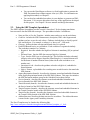
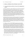
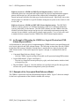
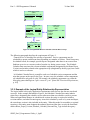
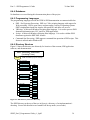
NYSDOT Task 2.A Extension Transit Schedule Data Exchange Architecture (TSDEA) SDP Guidance Documentation PART 3 – SDP Programmer’s Guide Version 1.0 June 30, 2008 By Consensus Systems Technologies, Inc. 617-983-3364 Prepared for: New York State Department of Transportation Part 3 – SDP Programmer’s Guide 30 June 2008 Table of Contents 1. OVERVIEW .................................................................................................... 5 1.1. Purpose of Document....................................................................................................................... 5 1.2. Document Structure and Objectives............................................................................................... 5 1.3. Programmer’s Guide Organization................................................................................................ 6 2. A GUIDE TO TRANSLATING NATIVE DATA TO SDP ................................. 7 2.1. Templates, Quick Start and User Requirements Guidance.......................................................... 7 2.2. A Simple Process for Translating Native to SDP .......................................................................... 7 2.3. Using the SDP Template Spreadsheet ............................................................................................ 9 3. GUIDANCE ON BUILDING A PHYSICAL DATABASE FROM THE SDP... 10 3.1. Conceptual Data Reference Model as a Framework for Implementation Methods................. 10 3.2. Differences between the SDP CDRM and Implementation Methods ........................................ 10 3.3. An Example of Migrating the CDRM to a Logical, Physical and XML Schema Representation 11 3.3.1. 3.3.2. 3.3.3. 3.4. Database Scripts and Referential Integrity Issues....................................................................... 16 3.4.1. 3.4.2. 3.5. Referential Integrity Issues .........................................................................16 Temporal Integrity Issues ...........................................................................19 Implementation of a SDP Database in MS Access....................................................................... 20 3.5.1. 3.5.2. 3.5.3. 4. Example of the Conceptual Data Reference Model....................................11 Example of the Logical Entity-Relationship Representation......................12 Example of the Physical Database Implementation....................................14 Software Installation ...................................................................................20 Data Files ....................................................................................................21 Application Execution ................................................................................22 USING THE SDP XML SCHEMA FOR XML DOCUMENT VALIDATION ... 24 4.1. Introduction.................................................................................................................................... 24 4.2. Structure of the SDP XML Schema.............................................................................................. 24 4.3. Structure of the Schedule Calendar Date (SCD) XML Schema................................................. 25 4.4. Elements of the XML Schema....................................................................................................... 25 4.5. Validating XML Documents Using the XML Schema ................................................................ 25 SDPG_Part3_Programmers Guide_v1_0pdf 2 Part 3 – SDP Programmer’s Guide 4.6. 4.7. 30 June 2008 Using Altova XMLSpy................................................................................................................... 25 Microsoft MSXML2 Windows Scripting Host Application........................................................ 29 4.7.1. 4.7.2. Software Installation ...................................................................................29 Application Execution ................................................................................29 5. APPENDIX A: MSXSD.JS SOURCE AND BATCH FILES ......................... 31 6. APPLICATION DESIGN REFERENCE MANUALS..................................... 32 6.1. Introduction.................................................................................................................................... 32 6.1.1. 6.1.2. Intended Audience ......................................................................................32 SDP Application User’s Manuals ...............................................................33 6.2. SDP Application System Architecture ......................................................................................... 33 6.3. SDP Application Module Descriptions ......................................................................................... 35 6.4. Application Development Environment ....................................................................................... 35 6.4.1. 6.4.2. 6.4.3. 6.4.4. 6.4.5. 6.4.6. Open Source – Open Platform ....................................................................35 Operating Systems ......................................................................................35 Data Encoding Formats...............................................................................35 Databases ....................................................................................................36 Programming Languages ............................................................................36 Directory Structure......................................................................................36 6.5. Appendix A: LIBus2Sdp Conversion Setup and User’s Manual .............................................. 37 6.6. Appendix B: RTIF2Sdp Conversion Setup and User’s Manual ............................................... 37 6.7. Appendix C: STIF2Sdp Conversion Setup and User’s Manual................................................ 37 6.8. Appendix D: SDP Csv2Xml Conversion Setup and User’s Manual ......................................... 37 6.9. Appendix E: SDP Xml2Csv Conversion Setup and User’s Manual ......................................... 38 6.10. Appendix F: SDP Csv2Gtfs Conversion Setup and User’s Manual.......................................... 38 7. THE SDP AND METADATA ........................................................................ 39 7.1. Introduction.................................................................................................................................... 39 7.2. What is SDP Metadata?................................................................................................................. 39 7.3. Why SDP Metadata........................................................................................................................ 39 7.4. SDP Metadata XML Schema ........................................................................................................ 40 7.4.1. 7.4.2. 7.4.3. Overview.....................................................................................................40 SDP Metadata Requirements ......................................................................40 Metadata XML Schema Model...................................................................42 SDPG_Part3_Programmers Guide_v1_0pdf 3 Part 3 – SDP Programmer’s Guide 7.5. 30 June 2008 Appendix A: XMLSpy Schema Notation .................................................................................... 52 Table of Tables Table 1: Table 2: Table 3: Table 4: CDRM Entity with its Identifying and Non-Identifying Keys ............................16 SDP Access Database Operating System and Version Requirements.................21 SDP Application List...........................................................................................32 Requirement Description for SDP Metadata .......................................................40 Table of Figures Figure 1: Structure of SDP Four Guidance Documents.......................................................5 Figure 2: SDP Translation Process ......................................................................................8 Figure 3: Conceptual ER Model of Schedule Calendar Date Concept..............................12 Figure 4: Migrating from Conceptual to Logical Model ...................................................13 Figure 5: Logical Model of Schedule Calendar Date Concept ..........................................14 Figure 6: Physical Model of the Schedule Calendar Date .................................................15 Figure 7: SDP Database Application Directory Structure .................................................21 Figure 8: SDP Startup Macro Initialization Directory Prompt ..........................................22 Figure 9: SDP Startup Macro Initialization Directory Results ..........................................23 Figure 10: XMLSpy SDP Project File at Startup...............................................................27 Figure 11: XMLSpy Showing Validation Errors...............................................................28 Figure 12: MSXSD Application Showing a Validation Report ........................................29 Figure 13: MSXSD Application Showing Validation Error Report..................................30 Figure 14: Schedule Data Processing Data Flow Diagram................................................34 Figure 15: SDP Directory Structure Hierarchy..................................................................36 Figure 16: High Level SDP Metadata XML Schema ........................................................43 Figure 17: Metadata SDP XML Schema Model (from XMLSpy) ....................................44 Figure 18: SDP Metadata Attribute Group ........................................................................45 Figure 19: SDP Metadata XML Schema Fragment of Identification Element..................46 Figure 20: SDP Metadata XML Schema Fragment of Description Element.....................47 Figure 21: SDP Metadata XML Schema Fragment of Status Element .............................48 Figure 22: SDP Metadata XML Schema Fragment of Distribution Information Element 49 Figure 23: SDP Metadata XML Schema Fragment of Data Quality Element...................49 Figure 24: SDP Metadata XML Schema Fragment of Spatial Data Element....................50 Figure 25: SDP Metadata XML Schema Fragment of Code Set Element.........................50 Figure 26: SDP Metadata XML Schema Fragment of Special Conventions Element ......51 Figure 27: Example of the XMLSpy Diagram Notation ...................................................53 SDPG_Part3_Programmers Guide_v1_0pdf 4 Part 3 – SDP Programmer’s Guide 30 June 2008 1. Overview 1.1. Purpose of Document This SDP Programmer’s Guide is intended to assist developers and technical users in understanding how to convert agency schedule information into SDP format to allow the efficient exchange of schedule information between agencies in the New York City region. Part 3 SDP Programmer’s Guide contains several manuals that include tools, applications, physical databases, and XML Schema descriptions for implementation. Each Chapter is developed as a self-contained unit. Hyperlinks and file objects are embedded in the document for quick access. All the applications and user manuals included in this document were tested, however, in the event of a problem, please send a bug report to: [email protected]. 1.2. Document Structure and Objectives The SDP Programmer’s Guide is meant to provide technical information on the SDP to technical users, System Integrators and Application Developers. In order to meet the needs of the varied set of stakeholders a series of four Guidance documents were developed, as shown in Figure 1. Why Why What What 1. Overview -- why, what and map of documentation 2. Requirements Manual -- what is approach and requirements How How What What if… if… 3. Programmer’s Manual -- how and other technical guidance 4. Troubleshooting Manual -- lessons and support for issues Figure 1: Structure of SDP Four Guidance Documents The four sets of documents provide increasing levels of detail in understanding SDP and performing conversion of agency data to the SDP standardized format. Part 1 is intended for Program Managers, Analysts, Developers, and System Integrators. It provides an overview of SDP, including a high level overview of SDP model, as well as a discussion of resources and a glossary. SDPG_Part3_Programmers Guide_v1_0pdf 5 Part 3 – SDP Programmer’s Guide 30 June 2008 Part 2 is intended for Analysts and provides a more detailed framework & approach for the SDP, as well as a summary of the requirements that drove the development of the SDP. Part 3 is intended for Application Developers. It includes the data mapping approach, detailed conversion programs and user manuals, transformations, algorithms, “cheat sheets”, as well as implementation guidance on developing a physical database and XML validation. Part 4 is intended for System Integrators and Developers. It answers implementation questions, addresses integration issues (i.e., FAQ), and suggests solutions to commonly encountered problems. [Note: Part 4 will be implemented as part of the ongoing SDP Operations and Maintenance.] This document is Part 3 – SDP Programmer’s Guide. 1.3. Programmer’s Guide Organization The SDP Programmer’s Guide is divided into six stand-alone sections. Following this chapter, the Programmer’s Guide contains five sections, including: Chapter 2: Chapter 3: Chapter 4: Chapter 5: Chapter 6: A Guide to Translating Native Data to SDP Guidance on Building a Physical Database Using the SDP XML Schema for XML Document Validation Application Design Reference Manuals SDP and Metadata Each section may include hyperlinks to software, database or other large document. In addition, embedded files may be included in some chapters (e.g., the Application Design Reference Manual embeds six reference manual for six applications developed for the SDP). SDPG_Part3_Programmers Guide_v1_0pdf 6 Part 3 – SDP Programmer’s Manual 30 June 2008 2. A Guide to Translating Native Data to SDP The Guide to Translating Native Data to SDP describes the Guidance documents and tools, as well as a straight-forward process to map native schedule data to the SDP data concepts and formats. This manual is written for a technical reader who has XML, programming or database experience, and who has knowledge of the procedures used to translate one format to another. 2.1. Templates, Quick Start and User Requirements Guidance Several Guidance documents and tools were developed to support the translation of native data to SDP. The most useful documents for the “uninitiated” SDP translator are the following: SDP Quick Start Guide (http://www.consystec.com/tsdea/rstwg/SDP_QS_web.htm). This web document provides a high level overview of the requirements for translating native data to the mandatory elements of the SDP XML Document. Each mandatory element is described, along with its format and an example of its usage. In addition, conventions and code values are included in the document. SDP Template Spreadsheet. This MS Excel spreadsheet contains several pages that describe the entire SDP XML Schema (mandatory and optional). The template includes a comprehensive data concept glossary, as well as a description of all the codes and their values. The template will be described in Section 2.3 below. SDP Guidance Documents. As described in Section 1.2, the Guidance Documents consist of four parts (Ed. Note: part 4 will be implemented when the TSDEA is operating). Part 2: User Requirements Manual may be used as a comprehensive reference. o SDP Guidance Document Part 2 User Requirements: Part 2 may be used as a reference manual to view detailed examples of how different organizations map their native data to the SDP. In addition, the context and requirements related to the SDP data concepts are explained in this document. Chapters 4 through 10 describe how to map native data to the SDP data concepts by each branch in the SDP XML Schema. Appendix A: Considerations for Rail Transit discusses how to apply the SDP concepts to rail concepts, particularly those that differ from bus transit. A glossary is included in Appendix B of this document. 2.2. A Simple Process for Translating Native to SDP The process described in this section is similar to one used by many software developers to map one data format to another. As depicted in Figure 2, there are four major steps needed to map native data to SDP. SDPG_Part3_Programmers Guide_v1_0pdf 7 Part 3 – SDP Programmer’s Manual 2. Prerequisites XML, XML document, validation tools, SW/DBMS 1. Familiarize yourself with SDP Data Concepts 30 June 2008 3. Know native Schedule and related data semantics/ formats/ sources 4. Map native schedule semantics, relationships and formats to SDP XML Schema requirements Develop script for translating data Figure 2: SDP Translation Process Steps to build a native data to SDP XML document translator: 1. Familiarize yourself with SDP data concepts, codes and schema elements. The SDP Quick Start web document will provide the basic overview. To see more detail on nonmandatory element, see the User Requirements Manual (Part 2 Guidance document). 2. Check your skills and experience with key technical areas to develop script and code: Do you understand XML and SDP Schema organization? Do you have experience programming or developing modules for DBMS? Do you understand how to validate SDP XML documents? 3. Review your understanding of the semantics, relationships and formats of your organization’s native schedule and related data set(s) that cover the SDP data requirements. 4. Map Native Data to SDP concept Based on your knowledge of your schedule and related data meanings, identify the native table and field that maps to each SDP mandatory and optional element descriptions. Using the SDP Template Spreadsheet (to record your findings) or other tool: Map native types, flags and codes to SDP codes Map and document the obvious native data (and transformations) to SDP Identify missing identifiers; strategize on approaches for completing them while ensuring identifier uniqueness constraints. Identify missing mandatory data fields; strategize on approaches for completing them. Identify native data that is not represented (and should be) in the SDP. 5. Develop scripts and modules to translate codes, data types and extract data from native sources, and load the data into the SDP format. SDPG_Part3_Programmers Guide_v1_0pdf 8 Part 3 – SDP Programmer’s Manual 2.3. 30 June 2008 You can use the Data Mapper software (csv2xml) application to generate the XML Document from comma-separate value (csv) files. For information on applying this method, see Chapter 5. You can develop embedded procedures in your database to generate an XML Document. You can reuse procedures from any of the applications developed for this project. See Chapter 5 for user manuals and design documents. Using the SDP Template Spreadsheet The SDP Template Spreadsheet provides a useful “cheat sheet” for developing translations between native data and SDP data concepts. The spreadsheet includes 9 worksheets: Notes on How to Use the Template: includes notes on how to use the worksheets. CodeList: includes the SDP element name, description, XML code fragment and guidance on how to use the code values. Guidance includes how to classify special real-world objects. For example, a subway is a “heavy rail” – HR mode. Glossary: defines the data concepts and branch where it is placed. Each SDP Branch has its own worksheet. Each worksheet is organized similarly. The worksheet contains five Columns: o Required: describes whether the high level element is mandatory [M] or optional [O] o Element Name: lists the SDP data concept (high level element) o Type: lists the XML type or referenced type. This field also includes referential integrity rules such as unique, identifier (identifying key). A nested element will list the name of another Element Name (either on the same worksheet or on another one). o Questions to Ask: describes the guidance related to a high level, embedded or nested element. o Native Format: a placeholder for recording notes on which native data match the SDP element. AgencyRegistration (branch): describes the elements, nested and embedded elements in the AgencyRegistration branch of the SDP XML Schema. This page also includes the SDP Document attribute group for the ScheduleVersion data concept. Service (branch): describes the elements, nested and embedded elements in the Service branch of the SDP XML Schema. Transit Network (branch): describes the elements, nested and embedded elements in the Service branch of the SDP XML Schema. Transit Gazetteer (branch): describes the elements, nested and embedded elements in the Transit Gazetteer branch of the SDP XML Schema. Transit Facility (branch): describes the elements, nested and embedded elements in the Transit Facility branch of the SDP XML Schema. AddressStructure: describes the data structure for an address. The AddressStructure is nested in the Agency and TransitStop elements. The Excel Template may be found at the following link: http://www.consystec.com/tsdea/rstwg/documents/SDPxml_template_v1_0.xls SDPG_Part3_Programmers Guide_v1_0pdf 9 Part 3 – SDP Programmer’s Manual 30 June 2008 3. Guidance on Building a Physical Database from the SDP 3.1. Conceptual Data Reference Model as a Framework for Implementation Methods As described in Guidance Part 2 volumes, the SDP Project used a system engineering approach for developing user driven requirements for schedule and related data. A set of Use Cases on Integrated Trip Planning, Dynamic Generation and Presentation of Public Timetables, and Generation of Ad Hoc Scheduling were developed to identify the specific schedule data requirements for these downstream applications. The effort wanted to ensure that the data meaning and relationships were well defined. A Conceptual Data Reference Model (CDRM) was developed to meet that need. The CDRM is meant to be used as a framework to unambiguously describe the SDP data concepts and their relationship to each other. Different technical methods may be used to physically represent and store schedule data. The three methods include: logical data model, physical database, and XML Schema. The major objective of the project was to implement the XML Schema and validate the requirements in one or more downstream applications (related to the use cases). The SDP logical and physical methods provide alternative approaches for the storing the data. Different needs may exist for storing the data using a different method, yet ensuring that there is a seamless, automated way to transfer the data from format to format. In fact, the csv2xml application, described in Chapter 5 of this document, uses a comma separated value (csv) representation which may be described as a logical model of the CDRM to convert native data using the interim format to an XML document. A physical database is a more efficient way to store data sets of different versions and multiple agencies together then file server containing multiple SDP XML Documents. 3.2. Differences between the SDP CDRM and Implementation Methods The SDP CDRM uses an entity-relationship (ER) method to represent real-world phenomena. The model is driven by a set of requirements described by current, local practice and by best practices advocated by the information technology and transit industries. The CDRM uses an abstract ER diagram (ERD) modeling method to represent these real-world phenomena. Although a similar notation is used to describe the Logical and Physical models, they do not include the same information or serve the same purpose. Differences between the CDRM and Logical, CDRM and Physical and CDRM and XML Schema models are described below. Difference between a CDRM and SDP Logical Entity Relationship Model: A CDRM shows the relationship between entities, but does not carry related keys to related entities. For example, in a system that supports more than one schedule version per agency, the schedule version identifier must be included in every entity in the logical model. A logical model (expressed as an ERD) shows these primary and foreign keys, and thus describes key storage requirements related to the data set. The CDRM makes no assumptions about how a model is applied; rather, it describes real-world relationships. SDPG_Part3_Programmers Guide_v1_0pdf 10 Part 3 – SDP Programmer’s Manual 30 June 2008 Difference between a CDRM and SDP Physical Implementation: Similar to the relationship between a conceptual and logical model, the physical implementation supports primary and foreign keys, the procedures that validate these relationships, and specific formats and syntax related to each data type described in the model. Specifically, these rules and procedures are defined for a specific database management system such as Oracle 9i, MS Access 2003, etc. Difference between a CDRM and SDP XML Schema Implementation: The SDP XML Schema’s primary purpose is to facilitate the sharing of data across different information systems, particularly via the Internet. The SDP XML Schema uses the CDRM to describe schedule and related data concepts and preserve the relationship requirements among data concepts for one schedule version and for a single transit operator. A set of rules were used to migrate the data concepts from the CDRM to the XML Schema implementation. 3.3. An Example of Migrating the CDRM to a Logical, Physical and XML Schema Representation As described above, there are rules for implementing the CDRM from the conceptual framework to its logical, physical and XML schema formats. The following sections show how the CDRM for the same data concept, Schedule Calendar Date, is transformed to a logical, physical, and XML Schema model. Each model depicted in Figures 1 through 4, is summarized in the list below: • Conceptual Data Reference Model—Figure 3 - Note the CDRM, Logical and Physical models are all represented using ERD notation. • Logical ERD Model—Figure 4 and Figure 5 - Note the key identifiers become primary keys (pk), and related entities include related or foreign keys (fk); • Physical Model—Figure 6. Note the attributes are specified with specific data types that reference the specific database management system specifications. 3.3.1. Example of the Conceptual Data Reference Model The CDRM is expressed as an Entity Relationship Diagram (ERD). Figure 3 shows an example for the basic representation of the schedule calendar date concept. SDPG_Part3_Programmers Guide_v1_0pdf 11 Part 3 – SDP Programmer’s Manual 30 June 2008 Route_Depot_Version (SDP) routeDepotVersionID <pi> <M> activationDate <M> deactivationDate <M> <<data type>> Schedule_Calendar_Date Relationship_47 (SDP) calendarDate <pi> <M> dayType <pi> <M> placementDate <M> activationDate <M> deactivationDate <M> 53 Day_Type (SDP) dayTypeDescription <M> agencyID timeBegin timeEnd <pi> <M> dayType is defined by defines 4 Calendar_Date <pi> <M> date dayOfWeek <M> holiday Figure 3: Conceptual ER Model of Schedule Calendar Date Concept The following paragraph describes the requirements of Figure 3: “Transit service is scheduled for each day of operation. Service components may be scheduled to operate on different dates depending on a number of factors. These factors may be schedule based; for example, special trips are designated when there is an event at Shea Stadium or service to evacuate workers from the city during a snow storm. The Schedule Calendar Date associates the relevant schedule components (designated by the Route Depot Version) and an index related to the appropriate trips (designated by the day type) into a table which is used as a reference. “A Schedule Calendar Date is created for each set of schedule version components and the trips that operate on the specific dayType. In some cases, the schedule version components are scheduled for only part of a day, for example, the schedule components vary when the Mets play games that begin at 5 p.m. versus at 7 p.m.” [from SDP Functional Requirements, p. 102] 3.3.2. Example of the Logical Entity-Relationship Representation The logical model is driven by application requirements related to how the data are stored and accessed. In the example illustrated in Figure 4, the Schedule Calendar Date entity inherits related keys designating the schedule version when more than one schedule version is present. When an organization changes its schedule mid-version, the entity is required to include a revision number, and when a transit agency issues their schedule by route or by route and depot, the route-depot version is also included in the entity. When this model is extended to a regional repository, each entity must designate the authority that issued the data, as such, the functional entities Route_Depot_Version, Schedule_Calendar_Date and Day_Type include the agency SDPG_Part3_Programmers Guide_v1_0pdf 12 Part 3 – SDP Programmer’s Manual 30 June 2008 identifier (agencyID). The actual implementation of the conceptual to logical model may be seen in Figure 5. Calendar_Date <pi> <M> date dayOfWeek <M> holiday defines 4 is defined by <<data type>> Schedule_Calendar_Date (SDP) Route_Depot_Version (SDP) routeDepotVersionID <pi> <M> activationDate <M> deactivationDate <M> <pi> <M> Relationship_47 calendarDate dayType <pi> <M> placementDate <M> activationDate <M> deactivationDate <M> Use to distinguish different schedule or route/depot versions. When multiple agencies and versions are present, the table will include foreign keys: scheduleVersionID, revisionNo and agencyID. Day_Type (SDP) 53 dayTypeDescription <M> timeBegin timeEnd <pi> <M> dayType When storing multiple schedule versions, table will include foreign keys: scheduleVersionID, revisionNo and/or routeDepotVersionID, too. Add foreign key agencyID to all tables when integrating with multiple agencies. Figure 4: Migrating from Conceptual to Logical Model SDPG_Part3_Programmers Guide_v1_0pdf 13 Part 3 – SDP Programmer’s Manual 30 June 2008 Figure 5: Logical Model of Schedule Calendar Date Concept 3.3.3. Example of the Physical Database Implementation The physical model is similar to the logical model except the data types are defined by the database management system. The physical database also supports procedures that enforce referential integrity triggers (primary and foreign keys) when data are added, changed or deleted from the database. A generic physical model for the Schedule Calendar Date concept is illustrated in Figure 6. As is shown in the figure, this is similar to the logical model shown in Figure 5 except for defining specific data types and showing the procedures. For organizations with specific database management systems, the logical and physical representations are somewhat redundant since logical and physical models will use the same data type definitions. SDPG_Part3_Programmers Guide_v1_0pdf 14 Part 3 – SDP Programmer’s Manual 30 June 2008 ScheduleVersion PK scheduleVersionID CHAR(10) scheduleVersionDescription pickNo activationDate deactivationDate placementDate CHAR(10) CHAR(10) CHAR(10) CHAR(10) CHAR(10) CalendarDate PK date DATETIME dayOfWeek holiday CHAR(10) TEXT(10) ScheduleRevision PK,FK1 PK scheduleVersionID revisionNumber activationDate deactivationDate placementDate scheduleVersionType history CHAR(10) CHAR(10) CHAR(10) CHAR(10) CHAR(10) CHAR(10) CHAR(10) Schedule_Calendar_Date PK,FK1 PK,FK2 date dayType DATETIME CHAR(10) FK3 FK3 FK3 placementDate activationDate deactivationDate revisionNumber scheduleVersionID routeDepotVersion DATETIME DATETIME DATETIME CHAR(10) CHAR(10) CHAR(10) RouteDepotVersion PK,FK1 PK,FK1 PK revisionNumber CHAR(10) scheduleVersionID CHAR(10) routeDepotVersion CHAR(10) routeID depotID activationDate deactivationDate CHAR(10) CHAR(10) CHAR(10) CHAR(10) Day_Type PK dayType CHAR(10) dayTypeDescription TEXT(10) timeBegin DATETIME timeEnd DATETIME Figure 6: Physical Model of the Schedule Calendar Date SDPG_Part3_Programmers Guide_v1_0pdf 15 Part 3 – SDP Programmer’s Manual 30 June 2008 3.4. Database Scripts and Referential Integrity Issues Using specialized data modeling software, the CDRM may be used to generate a physical database loading script. The physical database should be optimized for its use. Because primary and foreign keys are not specifically identified in the conceptual model, tables are not optimized for queries, and multiple agencies or versions are not assumed in the CDRM, the script will need to be revised and augmented. For inquiries on obtaining a script to generate a SDP physical database, please contact: [email protected]. 3.4.1. Referential Integrity Issues Referential integrity in a database ensures that tables ensures the identity and relationships among data concepts are unique, consistent and unambiguous. The utility to ensure these characteristics are the assignment of primary and foreign keys in the physical database management system. Although the CDRM does not use the terms primary and foreign keys, it classifies one or more identifying keys (primary keys) for each entity (which becomes a table in the physical database). The model also inserts related identifying keys in some entities and in some cases there are non-identifying keys in an entity. The CDRM entity, their identifying keys, related identifying keys and non-identifying keys are listed in Table 1: CDRM Entity with its Identifying and Non-Identifying Keys. Table 1: CDRM Entity with its Identifying and Non-Identifying Keys IDENTIFYING KEY NAME IDENTIFYING RELATED KEY NAME(S) agencyID effectiveDate endDate locationID effectiveDate endDate amenityID amenityCode blockID blockTime seqNo date connectionID OTHER RELATED KEYS blockID tripID routeID From: locationID To: locationID dayType depotID SDPG_Part3_Programmers Guide_v1_0pdf ENTITY Agency Amenity Amenity_Type scheduleVersionID Block effectiveDate endDate scheduleVersionID Block_Event_Time scheduleVersionID Block_Trip_Sequence Calendar_Date Connection_Seg effectiveDate endDate dateTimeBegin Day_Type dateTimeEnd scheduleVersionID transitFacilityID Depot 16 Part 3 – SDP Programmer’s Manual IDENTIFYING KEY NAME connectionNum facPCID locationID mode noteAssociationID IDENTIFYING RELATED KEY NAME(S) To: tripTime, tripID, routeID From: tripTime, tripID, routeID transitFacilityID noteID tripID organizationUnitID passAccessID plantCompID OTHER RELATED KEYS ENTITY locationID effectiveDate endDate scheduleVersionID Event_Connection featureType_cd effectiveDate endDate noteID passengerAccessCod e patternID 30 June 2008 tripTime scheduleVersionID effectiveDate endDate scheduleVersionID effectiveDate endDate agencyID effectiveDate endDate locationID effectiveDate endDate Facility_Plant_Component Location Mode Note_Association Note_Entry Organizational_Unit Passenger_Access_Compone nt Passenger_Access_Type routeID componentID (amenityID, transitFacilityID, stopID, trackID, passAccesID) featureType_cd trackNo stopID portalID SDPG_Part3_Programmers Guide_v1_0pdf routeDirection Pattern scheduleVersionID effectiveDate endDate effectiveDate Plant_Component endDate Platform_Track locationID effectiveDate endDate Portal 17 Part 3 – SDP Programmer’s Manual IDENTIFYING KEY NAME relativeLocationID routeID IDENTIFYING RELATED KEY NAME(S) locationID routeBeginDate routeEndDate routeDepotVersionID revisionNo scheduleVersionI D routeDirection routeID routeGroupingID routeGroupingCode calendarDate revisionNumber scheduleVersionID scheduleVersionI D activationDate deactivationDate scheduleVersionType identifier revisionNo plantCompID statusTypeCode timepointID tth routeID routeDirection trackNo transferClusterName transitFacilityID tranPathID locationID SDPG_Part3_Programmers Guide_v1_0pdf 30 June 2008 OTHER RELATED KEYS ENTITY Relative_Location Route mode scheduleVersionID effectiveDate endDate dayType Route_Depot_Version effectiveDate endDate scheduleVersionID Route_Direction scheduleVersionID Route_Grouping effectiveDate endDate Route_Grouping_Type Schedule_Calendar_Date Schedule_Revision agencyID locationID activationDate deactivationDate placementDate modificationDate creationDate Schedule_Version Schedule_Version_Type Service_Area Status Status_Code_Type locationID Timepoint scheduleVersionID effectiveDate endDate scheduleVersionID Timetable_Header effectiveDate endDate Set of locationID effectiveDate endDate locationID effectiveDate endDate Ordered list of locationID Track Transfer_Cluster Transit_Facility Transit_Path 18 Part 3 – SDP Programmer’s Manual IDENTIFYING KEY NAME IDENTIFYING RELATED KEY NAME(S) 30 June 2008 OTHER RELATED KEYS ENTITY effectiveDate endDate seqNo locationID patternID locationID (first & Ordered list of last) locationID patternID locationID effectiveDate endDate routeID scheduleVersionID dayType effectiveDate endDate seqNo stopID tripID tripEventTypeCode tripTime tripID routeID Transit_Path_Event Transit_Point_Event Transit_Stop Trip Trip_Event_Type scheduleVersionID Trip_Time 3.4.2. Temporal Integrity Issues Transit schedule and related data are composed of sets of data with differing, overlapping and temporary data versions and revisions in different states. To that end, temporal data principles are applied to the major entities using two fields for time: effectiveDate and endDate. The principles for preserving the history while enabling so-called redundant data to remain in the database necessitate including the two dates as primary keys. In some cases, like ScheduleVersion, Route, Day Type, Plant Component Status, additional temporal keys are included (e.g., activationDate/deactivationDate, routeBeginDate/routeEndDate) in order to allow for temporary data with similar identifying keys to remain in the For example, TriMet implemented this approach in their database. The description of their use of dates is described in a passage from the FTA Best Practices for Using Geographic Data in Transit: A Location Referencing Guidebook: “…The Location Table cannot lose the old record keyed to the Location ID; therefore, a method to manage the updated records must be implemented. “Adding one attribute to the unique identifier (primary key) of the Location Table, called location_end_date, can achieve this consistency. When a location ID is first introduced, the location_begin_date is set to the date of first use (see Example Table #1 below: 5-103 is the new date). The location_end_date is set to a date in the far-off future (in Example Table #1, location_end_date is 12-31-9999). If a change is made to one of the Location Table attributes, for example, if the Public_Description is changed, the location_end_date for the existing row is set to the date of closure (in Example Table #2, the date is now 6-30-03). In addition, a new row (or record) may be introduced for the SDPG_Part3_Programmers Guide_v1_0pdf 19 Part 3 – SDP Programmer’s Manual 30 June 2008 Location ID. On the new record, the location_begin_date value is set for the original location_end_date plus one day later (7-01-03, and the location_end_date is set to a date in the far-off future (12-31-9999). Using this approach, a consistent set of values is provided for the Location ID with the referring transit feature matching the Location ID, and inclusive of location_begin_date and location_end_date. “Example of the Public_Description changing: Example Table #1 Loc_ID 5 location_begin_date 5-1-03 location_end_date 12-31-9999 Public_Description Union & 5th Example Table #2 Loc_ID 5 5 location_begin_date 5-1-03 7-1-03 location_end_date 6-30-03 12-31-9999 Public_Description Union & 5th MLK& 5th “In this manner, historical data can be matched accurately. Alternatively, if the location changes (e.g., nearside to farside), a new ID (and new record) is created and the old ID is retired.” [from FTA-NJ-26-7044-2003.1, Best Practices for Using Geographic Data in Transit: A Location Referencing Guidebook , April 2005. pf., 79. free download from http://www.fta.dot.gov/documents/LRG_FinalPublication.pdf] Many of the principles for managing temporal databases may be found in: Richard T. Snodgrass, Developing Time-Oriented Database Applications in SQL. Morgan Kaufmann Publishers, San Francisco CA, 2000. – free download at http://www.cs.arizona.edu/people/rts/tdbbook.pdf 3.5. Implementation of a SDP Database in MS Access The SDP demonstration contains a sample Microsoft Access database instance of the SDP (Sample SDP database). The referential integrity procedures and triggers are not installed in this database. The database executes a macro at startup that reads a set of SDP csv file format files at run-time and loads the data into the database. The user may then view table data and create new queries to examine the SDP data and structure. 3.5.1. Software Installation The Sample SDP database contains a startup macro application written in Visual Basic for Access that runs under the Windows Operating System. Table 2 outlines the operating system and version requirements for the database instance example. SDPG_Part3_Programmers Guide_v1_0pdf 20 Part 3 – SDP Programmer’s Manual 30 June 2008 Table 2: SDP Access Database Operating System and Version Requirements System SDP XML Schema Microsoft Access MS Windows Version Version 1_0 2003 SP2 Windows XP Prerequisites: Microsoft Windows and Access 2003 Database. The TSDEA web site (http://www.consystec.com/tsdea/rstwg/docs.html) contains a copy of the Microsoft Access 2003 database content file, but not the database software itself. 3.5.2. Data Files 3.5.2.1. Set Up the SDP Directory Structure The figure below shows where to install the SDP instance database, called sdp_db.mdb. You may choose any SDP root path (directory). We have labeled this SDP root as $SDP in the figure below and use this label in the remainder the user’s manual. If you are copying files from the CD, the directory structure is set up as described in Figure 7. SDP Database Application Example Directory Structure $SDP is a directory of your choosing. $SDP SDP_data Application Input Files SDP CSV files Application Software sdp_db.mdb Module LIBus RTIF STIF MNR LIRR MTABus CoachUSA Figure 7: SDP Database Application Directory Structure The Sample SDP Database Instance is located in the SDP_data sub-directory of the $SDP directory. We will use a forward-slash notation to indicate sub-directory relationships of directory tree, for example, $SDP/SDP_processing. SDP CSV data files, which can be imported to the database at run-time are located in an agencyspecific directory of $SDP/SDP_data/, for example, $SDP/SDP_data/LIBus for Long Island Bus, and $SDP/SDP_data/RTIF for New York City Transit Rail files. 3.5.2.2. List of SDP CSV Data Input Files The Sample SDP database reads CSV data from an agency-specific sub-directory of $SDP/SDP_data/”agency”. The list of files read depends on the agency and whether the agency SDPG_Part3_Programmers Guide_v1_0pdf 21 Part 3 – SDP Programmer’s Manual 30 June 2008 provides bus, commuter rail, or subway, etc. service. The list of files, using the LIBus as an example, is listed below: • sdp_agency.csv • sdp_direction.csv • sdp_location.csv • sdp_Note.csv • sdp_NoteTimeAssoc.csv • sdp_NoteTripAssoc.csv • sdp_pattern.csv • sdp_patternEventList.csv • sdp_relativeLocation.csv • sdp_route.csv • sdp_rtDepotVersion.csv • sdp_RtDirection.csv • sdp_scheduleRevision.csv • sdp_scheduleVersion.csv • sdp_stop.csv • sdp_TimeEventType.csv • sdp_timepoint.csv • sdp_trips.csv • sdp_tripTimes.csv 3.5.2.3. List of SDP Tables The output of the initialization macro is a series of tables with the same names as the csv files imported. 3.5.3. Application Execution AutoExec Macro Application Execution: • AutoExec Macro: At startup the sdp_db.mdb database executes a software module that prompts the user for a name of a sub-directory where SDP csv files are located: for example, libus, rtif, stif, mnr, lirr, mtabus, etc. An example of the prompt display is shown in Figure 8: Figure 8: SDP Startup Macro Initialization Directory Prompt Once the data files are loaded the application will display “Done!”. SDPG_Part3_Programmers Guide_v1_0pdf 22 Part 3 – SDP Programmer’s Manual 30 June 2008 To launch the MS Access database, navigate to the $SDP/SDP_data directory. If you are using a graphical interface to navigate to the $SDP/SDP_data directory, then double-click on the file called sdp_db.mdb to start the application. After startup MS Access will contain a list of tables that correspond with the csv files imported. This is shown in Figure 9: Figure 9: SDP Startup Macro Initialization Directory Results SDPG_Part3_Programmers Guide_v1_0pdf 23 Part 3 – SDP Programmer’s Guide 30 June 2008 4. Using the SDP XML Schema for XML Document Validation 4.1. Introduction The Transit Schedule Data Exchange Architecture (TSDEA) project describes the exchange requirements for schedule and related data. These data requirements are incorporated into Schedule Data Profile (SDP) reference data model and implemented into the SDP XML Schema. This tutorial provides a brief overview of SDP XML Schema elements, and then describes two applications that use the SDP XML Schema to validate XML documents. A thorough treatment of the XML schema implementation and conceptual data reference model is contained in Chapter 2 of SDP Guidance Documentation Part 2: User Requirements. One of the advantages of XML is the relative ease of verification of conformance with an XML schema specification. Furthermore, software tools that are easy to use are readily available. Two applications that validate XML documents are discussed in this chapter. Finally, XML, which is written in ASCII, is portable across system platforms. One disadvantage of using XML documents is the relative large size of the document, routinely ranging between 5 to 15 megabytes in size, based on a representative sample of SDP XML documents. References: SDP Guidance Documentation Part 2: User Requirements Version 1.0, June 2008 The intended audience f this manual includes: • System developers and data modelers interested in creating valid SDP XML data; and • System managers responsible for setting up the run-time environment for SDP applications 4.2. Structure of the SDP XML Schema The SDP XML Schema is comprised of four files. These are listed below: • SDP_XML_Schema_v1_0.xsd: This is the base schema, which imports the SDP_Common and SDP_Domain schemas. It defines the structure of the SDP at the highest level. The SDP100 root element contains the following: o AgencyRegistration o Service o TransitNetwork o TransitGazatteer o TransitFacilities • SDP_common_v1_0.xsd – Include a definition of complex elements included by the highest level elements of the SDP. • SDP_domain_v1_0.xsd – Includes a definition of identifiers and code enumerations used in the SDP. SDPG_Part3_Programmers Guide_v1_0pdf 24 Part 3 – SDP Programmer’s Guide • 30 June 2008 GML_geometry.xsd - Contains definitions of the Geography Markup Language (GML) used in the SDP. 4.3. Structure of the Schedule Calendar Date (SCD) XML Schema A second schema that is part of the demonstration project is the Schedule Calendar Date schema, which is made up of two files. These are listed below: • SDP_Schedule_Calendar_Date_v1.xsd: This is the base schema, which imports the SDP_domain_scd schema. It defines the structure of the Calendar and Schedule_Calendar_Date. The Calenday root is comprised of Schedule_Calendar_date elements. • SDP_domain_scd_V1_0.xsd – Includes a definition of identifiers and code enumerations used in the SCD. 4.4. Elements of the XML Schema The SDP Reference Data Model is an implementation neutral representation of the static design that fulfills the SDP user requirements. The SDP data model describes the static data structure (data relationships and valid value rules) for the information used in SDP applications. The SDP data model specifies the following: • Sequence and order of data • Multiplicity, or number of times, a data element can be represented • Defines re-usable types (for example, longitude and latitude are used together, so a reusable point type may be defined) • Specifies mandatory (1 of more required) and optional (0 or more required) data elements • Specifies data value ranges and other constraints (for example, only the floating point numbers -90.000000 through 90.000000 may be used to define a latitude value, only the following valid text codes may be used to describe a dayType: “weekday”, “mon”, “tue”, …). • Key References 4.5. Validating XML Documents Using the XML Schema The SDP demonstration project used the Altova XMLSpy software and a Microsoft Windows Scripting Host application developed as part of the demonstration project to validate both the XML schemas and XML documents. How to use these two applications to validate XML documents are the topics of Section 4.6 and Section 4.7 below. 4.6. Using Altova XMLSpy Figure 10 on the following page shows XMLSpy after startup of the sdp.spp, an XMLSpy project file. The XMLSpy project file contains a list of schema files and XML documents. A portion of the sdp_MNR_Base_April2008.xml file is shown in the center. At the bottom of the figure, and part of the XMLSpy application, is a panel containing a Validation Report that indicates that the sdp_MNR_Base_April2008.xml document is valid. This means that the XML document conforms to all the schema rules including: • Sequence and order of elements • All mandatory elements present • All data content within the value constraints SDPG_Part3_Programmers Guide_v1_0pdf 25 Part 3 – SDP Programmer’s Guide 30 June 2008 If we change one of the data values to an incorrect value, for example the effectiveDate attribute of the <Agency> element to 2008-13-01, and run the validation, the XMLSpy application will provide a description of the error in the Validation Report panel at bottom, highlight the location of the error in the document, and print the xPath location of the error found. This is shown in Figure 11. SDPG_Part3_Programmers Guide_v1_0pdf 26 Part 3 – SDP Programmer’s Guide 30 June 2008 Validate Document Button XML Documents XML Schema Validation Report Figure 10: XMLSpy SDP Project File at Startup SDPG_Part3_Programmers Guide_v1_0pdf 27 Part 3 – SDP Programmer’s Guide 30 June 2008 Validation Error Report Figure 11: XMLSpy Showing Validation Errors SDPG_Part3_Programmers Guide_v1_0pdf 28 Part 3 – SDP Programmer’s Guide 30 June 2008 4.7. Microsoft MSXML2 Windows Scripting Host Application 4.7.1. Software Installation A sample application, msxsd, based on the MSXML2, an XML processor dynamic link library (DLL) that comes with the Microsoft Internet Explorer application is included on the application CD. The msxsd is a javascript application what accesses the MSXML2 DLL to validate an XML document against an XML Schema. The table below outlines the operating system and version requirements for the database instance example. System SDP XML Schema Windows Scripting Host Microsoft XML DLL MS Windows Version Version 1_0 5.6 2 Windows XP Prerequisites: Microsoft Windows Scripting Host. The attached CD contains a copy of the javascript, but not the Windows Scripting Host software nor the MSXML2 DLL. Appendix A of this chapter contains a copy of the javascript source and batch file to execute the code under the Windows Scripting Host. 4.7.2. Application Execution To start the msxsd application, navigate to the $SDP/SDP_schemaValidation/MNR directory. Then, double-click on the file called validate_MNR_SdpXml.bat to start the application. If the file is valid, then the following prompt will display (see Figure 12): Figure 12: MSXSD Application Showing a Validation Report An example showing an error report message is in Figure 13: SDPG_Part3_Programmers Guide_v1_0pdf 29 Part 3 – SDP Programmer’s Guide 30 June 2008 Figure 13: MSXSD Application Showing Validation Error Report SDPG_Part3_Programmers Guide_v1_0pdf 30 Part 3 – SDP Programmer’s Guide 30 June 2008 5. Appendix A: MSXSD.JS Source and Batch Files File: msxsd.js Validate XML Document Against Schema // validate parameters if(WScript.Arguments.length != 3) { WScript.Echo("msxsd takes three arguments - datafile, namespace, schema - eg:"); WScript.Echo('msxsd books.xml "" books.xsd'); } else { var cache = new ActiveXObject("Msxml2.XMLSchemaCache.4.0"); cache.add(WScript.Arguments(1), WScript.Arguments(2)); var xmldoc = new ActiveXObject("Msxml2.DOMDocument.4.0"); xmldoc.async = false; xmldoc.preserveWhiteSpace = true; xmldoc.schemas = cache; xmldoc.load(WScript.Arguments(0)); if(xmldoc.parseError.errorCode != 0) WScript.Echo("There is a problem: " + xmldoc.parseError.errorCode + " " + xmldoc.parseError.reason); else WScript.Echo("no problems!"); } File: validate_MNR_SdpXml.bat msxsd SDP_MNR_Base_April2008.xml "http://www.tsdea.com/schema/SDP100" ../schema/SDP_XML_Schema_v1_0.xsd SDPG_Part3_Programmers Guide_v1_0pdf 31 Part 3 – SDP Programmer’s Guide 30 June 2008 6. Application Design Reference Manuals 6.1. Introduction The Transit Schedule Data Exchange Architecture (TSDEA) project describes the exchange requirements for schedule and related data. These data requirements are incorporated into Schedule Data Profile (SDP) reference data model and implemented into the SDP XML Schema Version 1_0 (posted May 23, 2008). This SDP Application Design Reference Manual describes the design elements and application development environment of SDP applications developed under the TSDEA demonstration project. The appendices describe the design details of the application software. The SDP Applications developed under this project fall into one of three categories: 1. Applications that convert from an agency’s native schedule data to an SDP format 2. Applications that convert between the two SDP file formats, XML and CSV 3. Applications that convert from the SDP CSV format to formats used by open-source third party initiatives The SDP Applications described in this design document are listed in Table 3: SDP Application List. Table 3: SDP Application List Native Data to SDP LIBus2Sdp – Converts Long Island Bus Native Data Files to SDP RTIF2Sdp – Converts New York City Transit RTIF Files to SDP STIF2Sdp – Converts New York City Transit STIF Files to SDP SDP CSV Format to XML and SDP XML Format to CSV Csv2Xml – Converts SDP CSV Files to XML Xml2Csv – Converts SDP XML Files to CSV SDP CSV Format to Third Party Open Source Initiatives Csv2Gtfs – Converts SDP CSV Files to Google Transit Feed Spec (GTFS) 6.1.1. Intended Audience The intended audience of this manual includes: • System developers interested in maintaining the existing SDP applications or creating new SDP applications • System managers responsible for setting up the run-time environment for SDP applications SDPG_Part3_Programmers Guide_v1_0pdf 32 Part 3 – SDP Programmer’s Guide 30 June 2008 6.1.2. SDP Application User’s Manuals SDP Application User’s Manuals (each developed as a separate document) have been written for a user interested in understanding how to use an SDP application, without the need to understand the details of the processing involved. These are listed below: • • • • • • SDP Application: LIBus2Sdp Conversion Setup and User’s Manual SDP Application: RTIF2Sdp Conversion Setup and User’s Manual SDP Application: STIF2Sdp Conversion Setup and User’s Manual SDP Application: SDP Csv2Xml Conversion Setup and User’s Manual SDP Application: SDP Xml2Csv Conversion Setup and User’s Manual SDP Application: SDP Csv2Gtfs Conversion Setup and User’s Manual 6.2. SDP Application System Architecture The SDP Application System Architecture, shown in Figure 14, describes the relationship of SDP applications and system interfaces (inputs and outputs). SDPG_Part3_Programmers Guide_v1_0pdf 33 Part 3 – SDP Programmer’s Guide 30 June 2008 Figure 14: Schedule Data Processing Data Flow Diagram SDPG_Part3_Programmers Guide_v1_0pdf 34 Part 3 – SDP Programmer’s Guide 30 June 2008 6.3. SDP Application Module Descriptions Each SDP application is comprised of one or more software modules. A software module, as used here, is a single file containing software code. This design document contains a complete description of the software modules used by all the SDP applications. A module is described completely by the following: • • Module Name - The software module name. Module Descriptions – A high-level description of the module’s processing and functions. • Inputs – The names of the files opened for the purposes of reading by the module. • Outputs – The names of the files opened for the purposes of writing by the module. • Startup Parameters – List of any parameters that may be passed into the file at startup, for example, command-line arguments. • Programming Language and Version – The programming language and version of the module. The Application User’s Modules contain a description of each software module. 6.4. Application Development Environment 6.4.1. Open Source – Open Platform The TSDEA is an open source, open platform project. All the software developed under the project is subject to an adapted Berkeley Open Source license. 6.4.2. Operating Systems The SDP demonstration is an open platform project. SDP applications were developed and tested under the Microsoft WindowsXP operating system. Several applications, early during development, were tested under the Linux operating as a proof-of-concept of the open platform philosophy. 6.4.3. Data Encoding Formats All data processed by the SDP applications is ASCII text data. No binary formats are specified and therefore files are cross-platform. The following summarized the data encoding formats of file content of the SDP applications: • Native Data Formats. The TSDEA SDP demonstration processes native ASCII format files for Long Island Bus and New York City Transit RTIF and STIF. • CSV – Comma-Separated Values (a.k.a. Comma-Separated Variables) is a standardized ASCII format for describing tabular information. CSV files optionally contain a header record listing column names following by rows containing values corresponding with the column names. • XML – eXtensible Markup Language uses a tag based notation for representing hierarchically organized (i.e., tree structure) data. SDPG_Part3_Programmers Guide_v1_0pdf 35 Part 3 – SDP Programmer’s Guide 30 June 2008 6.4.4. Databases No databases were used during this demonstration phase of the project. 6.4.5. Programming Languages The programming languages used in the TSDEA SDP demonstration are summarized below: • PHP – Pre Hypertext Processing. PHP is a C-like scripting language with support for Web processing. PHP is open-source and runs under a variety of operating systems. PHP is implemented under the Apache, Microsoft IIS, and other web servers. • VBScript. A Microsoft Windows Scripting Host language. It is used to process XML formatted information into CSV (xml2csv SDP application). • Jscript. A Microsoft Windows Scripting Host language. It is used to validate XML documents against the SDP XML schema. • Command-line Processing. PHP supports command-line operation of PHP scripts. This feature is utilized under WindowsXP. 6.4.6. Directory Structure Figure 15 shows the directory tree hierarchy for location of data content, SDP application software, and documentation. SDP Directory Structure (*Including Future) $SDP $SDP is a directory of your choosing. LIB_processing RTIF_processing LIBus STIF_processing Native_data RTIF STIF MNR SDP_processing SDP_xml2csv LIRR MTABus CoachUSA LIBus SDP_data RTIF GTFS_data STIF docs MNR CSVFormat LIRR schema MTABus CoachUSA Figure 15: SDP Directory Structure Hierarchy The $SDP directory at the top of the tree in figure is a directory of an implementation’s choosing. Several sub-directories are branches off the top node (or root node). SDPG_Part3_Programmers Guide_v1_0pdf 36 Part 3 – SDP Programmer’s Guide 30 June 2008 6.4.6.1. Native Data Processing and Data There are directories for the applications that process native data – LIB_processing, RTIF_porcessing, and STIF_processing. Below these directories that contain native data processing applications is a directory, called Native_data, that contains sub-directories for each an agency’s native format data. To date, Native_data directory contains the native data files for Long Island Bus, and the RTIF and STIF files of New York City Transit. The LIB_processing, RTIF_processing, and STIF_processing directories contain applications that convert the individual agency data from there native formats to the SDP CSV format. The CSV files are written to a specific sub-directory of SDP_data, one for each agency (native data source). 6.4.6.2. SDP Data Processing and Data The SDP_processing sub-directory contains the applications that quality check and convert the CSV outputs of the native data processing to SDP format files. This includes applications that convert SDP CSV to XML and SDP CSV to the Google Transit Feed Spec format. The SDP_xml2csv sub-directory contains the applications necessary to perform an XML schema validation of agency-specific XML documents. 6.5. Appendix A: LIBus2Sdp Conversion Setup and User’s Manual This manual contains guidance on the application LIBus2SDP Conversion of Long Island Bus Native Data Files to SDP. See http://www.consystec.com/tsdea/rstwg/docs.html to download the User Manual. See http://www.consystec.com/tsdea/rstwg/applications.html to download the application code and user manual. 6.6. Appendix B: RTIF2Sdp Conversion Setup and User’s Manual This manual contains guidance on the application RTIF2SDP Conversion of New York City Transit Rail Transit Interface Format Native Data Files to SDP. See http://www.consystec.com/tsdea/rstwg/docs.html to download the User Manual. See http://www.consystec.com/tsdea/rstwg/applications.html to download the application code and user manual. 6.7. Appendix C: STIF2Sdp Conversion Setup and User’s Manual This manual contains guidance on the application STIF2SDP Conversion of New York City Transit Surface Transit Interface Format Native Data Files to SDP. See http://www.consystec.com/tsdea/rstwg/docs.html to download the User Manual. See http://www.consystec.com/tsdea/rstwg/applications.html to download the application code and user manual. SDPG_Part3_Programmers Guide_v1_0pdf 37 Part 3 – SDP Programmer’s Guide 30 June 2008 6.8. Appendix D: SDP Csv2Xml Conversion Setup and User’s Manual This manual contains guidance on the application Csv2SDP which converts SDP CSV Files to a SDP XML Document. See http://www.consystec.com/tsdea/rstwg/docs.html to download the User Manual. See http://www.consystec.com/tsdea/rstwg/applications.html to download the application code and user manual. 6.9. Appendix E: SDP Xml2Csv Conversion Setup and User’s Manual This manual contains guidance on the application XML2CSV which converts a SDP XML Document format to SDP Comma Separated Value (CSV) files. See http://www.consystec.com/tsdea/rstwg/docs.html to download the User Manual. See http://www.consystec.com/tsdea/rstwg/applications.html to download the application code and user manual. 6.10. Appendix F: SDP Csv2Gtfs Conversion Setup and User’s Manual This manual contains guidance on the application Csv2GTFS which converts SDP CSV Files to the Google Transit Feed Specification (GTFS) files. The application uses the GTFS February 2008 version. See http://www.consystec.com/tsdea/rstwg/docs.html to download the User Manual. See http://www.consystec.com/tsdea/rstwg/applications.html to download the application code and user manual. SDPG_Part3_Programmers Guide_v1_0pdf 38 Part 3 – SDP Programmer’s Manual 30 June 2008 7. The SDP and Metadata 7.1. Introduction This chapter introduces the metadata for the Schedule Data Profile. Metadata is used to describe one or more SDP Documents that form the collection of a schedule version (including all revisions and route depot versions) or schedule version revision. 7.2. What is SDP Metadata? Metadata is often defined as “data about data”. It summarizes the “who, what, when, where, why and how” of the data set. Metadata helps people find data that is appropriate for their use. SDP metadata will help 1 : • • • • • • • preserve the data history so that it can be re-used or adapted, assess the age and character of your data set provide a place for agencies to document extensions to their data sets for internal or special projects and applications instill data accountability by requiring you to state what you know about the data and realizing what you don’t, but should, know about your data limit data liability by explicitly designating the effective and administrative limits of use of the data. monitor data development by regular review of the process steps completed and recorded within the metadata access the lineage and content of the data production process In theory, metadata is a “best practice”. In practice, metadata is time consuming and tedious. The geospatial industry has learned over the years that metadata is an important tool in order to effectively manage and re-use data resources. To this end, an SDP Document submitted for use should be accompanied by a metadata document. A data repository that stores a SDP Document should use the metadata document enable Data Consumers to discover the data resources available at the site. To aid in the collection of metadata, the data repository, when it registers the SDP Document, should support the documentation and importation of metadata components of the SDP Document submissions. 7.3. Why SDP Metadata The TSDEA Data Repository will serve as a portal in which consumers of schedule data may find resources submitted by downstate NY regional Operators. This portal environment requires a “registry” of information about the quality, fitness for use, dissemination policies and interfaces supported by each data set organization. In theory, the TSDEA will support multiple transit agency schedules; it may support several schedule versions and revisions for a single transit operator. Managing these data sets will provide information on the SDP Document submission’s identity, status, extensions, customizations, data quality and other information needed to describe the purpose, fitness for use and distribution policies. Management will be 1 List adapted from “Why bother with Metadata”, http://www.fgdc.gov/metadata/metadata-business-case SDPG_Part3_Programmers Guide_v1_0pdf 39 Part 3 – SDP Programmer’s Manual 30 June 2008 accomplished through a SDP Metadata XML Schema submission and metadata application programming interface (API). 7.4. SDP Metadata XML Schema 7.4.1. Overview The SDP Metadata XML Schema is composed of several “packages”. These packages are based on best practices identified by several metadata standards including • • • • ASTM E2468-05 - Standard Practice for Metadata to Support Archived Data Management Systems IEEE 1489/1488 ITS Data Dictionary and Message Set FGDC Content Standard for Digital Geospatial Metadata ISO 11179 – Metadata Registries The ASTM references seven categories of information that should be included in a metadata. They include: 1. 2. 3. 4. 5. 6. 7. Identification Information Data Quality Information Spatial Data Organization Information Spatial Reference Information Entity and Attribute Information Distribution Information Reference Information Many of the elements from the ASTM reference are incorporated in the requirement description for the SDP Metadata. 7.4.2. SDP Metadata Requirements This section describes the requirements that drive the SDP Metadata XML Schema. The needs are listed in Table 4. Table 4: Requirement Description for SDP Metadata # 1 Category Identification Information Requirements • SDP shall contain identification information about the submission and standards used to define an operator’s set of Schedule and Related Data. The information should include: o Originator/submitter (name, telephone and email) o Original registration date o Approval staff person (name, signature, date) o Publication date o List of SDP Files covered by this metadata (only one Schedule Version per metadata) o SDP Schema version used to produce SDP files o SDP Metadata Schema version SDPG_Part3_Programmers Guide_v1_0pdf 40 Part 3 – SDP Programmer’s Manual # Category 2 Description and Time Period of Content 3 Status 4 Schedule Calendar 5 Data Quality Information 6 Special Conventions 7 8 Code Set Extensions Spatial Dataset 30 June 2008 Requirements o Online linkages (e.g., maps, pdf timetables) • Abstract (general description of SDP files) • Schedule Version o revision • Activation date / deactivation date (or 12-12-9999) • Data sources (e.g., Scheduling Application, RTIF, including version numbers of applications or file descriptions) • Phase: registered, Levels 1-3 • Date entered phase • Estimated date for next schedule version update • Update frequency: schedule change frequency (biweekly, quarterly, semi-annually) • Processing and Change Logs o Tests conducted • Type, who, what, why, activation date, disposition of updated record(s), o Revision History • Lineage (actual processes used to convert data) o Transformation processes needed to convert data o Date recorded o change start date, change stop date • Calendar • List of holidays and special days • Schedule Calendar Days • Procedures (instructions) o Process of loading data set(s) o Transformations required to pass testing (levels 1-3) • List of Exceptions or Constraints o Exception descriptions o Date recorded • Schedule day (based on up to a 36 hours clock which may include a start time from the day before and end at a time the next day) • Naming convention for indexes (may be included in XML schema annotation) • Based on codes supported by SDP XML Schema. • Description of each location reference with respect to its measurement quality and datum or coordinate system (e.g., GPS, map coordinates using SP-NY), e.g., x-coordinate/ycoordinate pair is New York State Plane. Accuracy of measurement or map base may include its own metadata. o For example, the New York State Plane may reference the State GIS metadata link: http://www.nysgis.state.ny.us/gisdata/metadata/nysogs.sta SDPG_Part3_Programmers Guide_v1_0pdf 41 Part 3 – SDP Programmer’s Manual # Category 9 Distribution Information 30 June 2008 Requirements tepln.html o Default is NAD ’83 and UTM 18 o Default spherical coordinates units is decimal degrees with 6 decimal places • Linear reference units (e.g., feet, meters, decimeters; include precision, resolution and accuracy for measurement) o Default is feet • List of available interfaces • Contact Information o Name, telephone, email, URL When the TSDEA provides a capability to document and store the metadata, many of the requirements may be automatically or manually entered into a metadata document. The schedule calendar requirement was separated from the metadata and will be submitted as a separate document. Guidance information on the schedule calendar XML schema may be found in the SDP Guidance Part 2, Chapter 9. 7.4.3. Metadata XML Schema Model The Metadata XML Schema is described in this section. The high level SDP Metadata schema is depicted in Figure 16: High Level SDP Metadata XML Schema. The depiction includes the categories described in the Requirements Description. Each node of the schema includes the details related to the required information. SDPG_Part3_Programmers Guide_v1_0pdf 42 Part 3 – SDP Programmer’s Manual 30 June 2008 Metadata Identification (1) Description (1) Status (1) DistributionInformation (1) DataQuality (1..*) SpatialDataset (1) The conventions used to depict the XML Schema requirements are as follows: Each node branching from the root node (Metadata) has exactly one (1), one-to-many (1..*), or zero-to-many (0..*) number of records included in the node. This notation is only depicted in the top level schema model (Figure 1). Bolded attributes, elements and nodes are mandatory, that is at least one value must be included in the element or record. Note: the use of italics in this convention list refers to terms used by the XML Schema or XML standards. CodeSet (0..*) SpecialConventions (0..*) Figure 16: High Level SDP Metadata XML Schema Using the XMLSpy software (see Appendix A for description of the notation), the high level SDP Metadata XML Schema is depicted in Figure 17. The Metadata document attribute group is depicted in Figure 18. Figures 19-26 describe the high level elements in the schema. The schema is composed of three files, similar to the SDP XML Schema. The files include: Main Schema Document: SDP_Metadata_XML_Schema_V0.1.xsd Complex Type Descriptions: SDPM_common_V0.1.xsd Simple Type Descriptions: SDPM_domain_V0.1.xsd These documents may be found on http://www.consystec.com/tsdea/rstwg/docs.html. Although, a white paper describing the requirements was circulated during the TSDEA Project, the schema and requirements have not yet been implemented. SDPG_Part3_Programmers Guide_v1_0pdf 43 Part 3 – SDP Programmer’s Manual 30 June 2008 Figure 17: Metadata SDP XML Schema Model (from XMLSpy) SDPG_Part3_Programmers Guide_v1_0pdf 44 Part 3 – SDP Programmer’s Manual 30 June 2008 Figure 18: SDP Metadata Attribute Group SDPG_Part3_Programmers Guide_v1_0pdf 45 Part 3 – SDP Programmer’s Manual 30 June 2008 Figure 19: SDP Metadata XML Schema Fragment of Identification Element SDPG_Part3_Programmers Guide_v1_0pdf 46 Part 3 – SDP Programmer’s Manual 30 June 2008 Figure 20: SDP Metadata XML Schema Fragment of Description Element SDPG_Part3_Programmers Guide_v1_0pdf 47 Part 3 – SDP Programmer’s Manual 30 June 2008 Figure 21: SDP Metadata XML Schema Fragment of Status Element SDPG_Part3_Programmers Guide_v1_0pdf 48 Part 3 – SDP Programmer’s Manual 30 June 2008 Figure 22: SDP Metadata XML Schema Fragment of Distribution Information Element Figure 23: SDP Metadata XML Schema Fragment of Data Quality Element SDPG_Part3_Programmers Guide_v1_0pdf 49 Part 3 – SDP Programmer’s Manual 30 June 2008 Figure 24: SDP Metadata XML Schema Fragment of Spatial Data Element Figure 25: SDP Metadata XML Schema Fragment of Code Set Element SDPG_Part3_Programmers Guide_v1_0pdf 50 Part 3 – SDP Programmer’s Manual 30 June 2008 Figure 26: SDP Metadata XML Schema Fragment of Special Conventions Element SDPG_Part3_Programmers Guide_v1_0pdf 51 Part 3 – SDP Programmer’s Manual 30 June 2008 7.5. Appendix A: XMLSpy Schema Notation The XML Schema notation, as extracted from the XMLSpy application, is used to describe the organization and format of the SDP XML Schema. The Schema is based on a hierarchical organization where parent nodes or elements may contain child elements (which may in turn be a parent element to child elements). The XML Schema format and document instance are based on the standard notation of an XML Schema and instance document. Figure 27 below illustrates the different levels of the XML Schema and key notation, using Transit Facility as the example. In addition, the figure shows the type description for each element. A type reference may have one of the following prefixes or suffixes: • Prefix of “xsd” asserts the type is native to the XML standard • Suffix of “_id” implies the type is defined as an SDP identifier domain • Suffix of “_cd” implies an enumerated code type. A “Structure” in the type name implies that the element is a complex type. An element also includes the constraint on the number of times it is allowed. An element enclosed by a dotted lined box indicates that the element is optional. Elements that may be repeated will include a notation of the minimum and maximum (e.g., 0..∞) under the right hand corner of the element enclosure. “plantComponentList” is an example of an element that is optional, but may be repeated. One element is required when the element is enclosed with a solid line (and does not contain a min-max value). SDPG_Part3_Programmers Guide_v1_0pdf 52 Part 3 – SDP Programmer’s Manual 30 June 2008 Figure 27: Example of the XMLSpy Diagram Notation SDPG_Part3_Programmers Guide_v1_0pdf 53