1
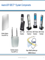
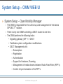
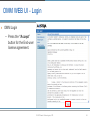
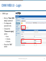
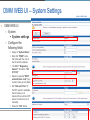
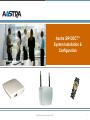
Aastra SIP-DECTTM System Installation & Configuration © 2007 Aastra Technologies, LTD. 1 Contents: » System Components & Architecture » Pre-installation planning » Installation & Configuration © 2007 Aastra Technologies, LTD. 2 Your Connection to the World. Aastra SIP-DECT™ System Components & Architecture © 2007 Aastra Technologies, LTD. 3 Aastra SIP-DECTTM System Components DECT 142 Handset Indoor Access Point RFP 32 Outdoor Access Point RFP 34 DECT 610d DECT 620d DECT 630d Handset Handset Handset Open Mobility Manager (OMM) Software © 2007 Aastra Technologies, LTD. 4 Access Point Features » Hardware RFP32 (Indoor Access Point) – OPTIONAL 120v AC power adapter (NOT INCLUDED) – Wall mounting kit – 2 internal space diversity antenna’s – Operating Conditions: Temperature: 23°F to 113°F (-5°C to 45°C) » Hardware RFP34 (Outdoor Access Point) – 2 external space diversity antenna’s – Optional wall mounting or mast mounting kits – PoE ONLY – Operating Conditions: Temperature: -13°F to 131°F (-25° C to +55°C) © 2007 Aastra Technologies, LTD. 5 SIP-DECT Access Point Characteristics All Aastra DECT devices conform to FCC & Regulatory Canada directives. FCC 15.323 & FCC 15.319 measured and released. US: NTP = 100mW (+20dBm) Frequency range: 1920 - 1930 MHz 5 Carriers available in the FCC / IC permitted band of 1920-1930Mhz DECT-channel • 0 • 1 • 2 • 3 • 4 TX Frequencies 1928,448 1926,720 1924,992 1923,264 1921,536 24 slots per carrier 8 slot-pairs or channels for voice 2 slot-pairs or channels for Hand-in, 2 slot-pairs for Signalling/Synchronization © 2007 Aastra Technologies, LTD. 6 Call Control and Media Paths IP-Phone WEB-Browser Call Control Ethernet LAN SIP Signalling Media Stream (RTP) Access Point control and Synchronisation interface Service via WEB - Configurator DECT Radio signalling © 2007 Aastra Technologies, LTD. 7 SIP-DECT System Architecture Call Control © 2007 Aastra Technologies, LTD. 8 Your Connection to the World. Aastra SIP-DECT™ Pre-Installation Planning © 2007 Aastra Technologies, LTD. 9 Pre-Installation » Preparation – Systematically collect a reference set of information to determine Coverage requirements Capacity Requirement Unique issues Network topology and configuration requirements Look to maximize synchronization redundancy where possible Go on site, verify and redesign as required – Initial Admin Info: Site address Site contact name, number, and email Technical (IS / IT) contact name, number, and email © 2007 Aastra Technologies, LTD. 10 Pre-Installation – Coverage Details 2 copies of scaled floor plan drawings with 1 copy showing: – – – – Areas where coverage is required Special areas of coverage (elevators, stairwells, washrooms, outdoors, etc) Areas where coverage is not necessary Areas of high handset density/ traffic Construction Materials – – – – – Exterior material type (metal, wood, concrete, etc)? Interior walls, type and height (metal, wood, concrete, drywall, tile, etc)? Ceiling, type and height (metal, wood, concrete, drywall, etc)? Door type (metal, wood, glass, etc)? Number of floors? Environment – Proximity to high power transmitters (Radio, TV, Cellular, etc.) – Nature of the environment Other existing wireless systems? (WLAN, Bluetooth, other DECT systems, etc) Office, conference, warehouse, store, etc © 2007 Aastra Technologies, LTD. 11 Pre-Installation – Capacity Details Number of Handsets required for initial deployment Busy Hour Traffic estimates if available – Network information SIP Server IP Address/Host Name and port number TFTP Server IP Address/Host Name Gateway/Router IP Address OMM Base Station IP Address OMM Secondary Station IP Address (if configuring resiliency) Subnet Mask Domain Name (optional) Domain Name Server (optional) Other RFP IP Addresses (if required) PoE Switches installed in the network infrastructure (or PoE injectors)? CAT5 Ethernet cabling? © 2007 Aastra Technologies, LTD. 12 Your Connection to the World. Aastra SIP-DECT™ Installation © 2007 Aastra Technologies, LTD. 13 Synchronization of Access Points » Access points synchronize with each other to enable calls to complete a seamless handover between access points. » Synchronization is via signaling over the wireless connections between access points. » Access points only need to sync with one other access point – ie they relay synchronization between access points. » Only access points that are synchronized together support call handover – ie allows users to roam across synchronized access points. » A group of synchronized access points is called a CLUSTER © 2007 Aastra Technologies, LTD. 14 Clusters » Access points can not always synchronize – ie different building, different floors. » Calls can be originated and terminated from all Clusters but handover can not occur between Clusters. » When access points are provisioned, they are grouped into designated Clusters © 2007 Aastra Technologies, LTD. 15 Installation (con’t) RFP Synchronization and Redundancy – – – – – One cluster with 5 RFPs. Each RFP has RF visibility (red line) to at least one other RFP. Visibility to more than 1 RFP provides redundant synchronization links and improve reliability. If a RFP loses synchronization, it will go “Inactive” unless it has redundant synchronization links that it can utilize. Once all active calls are released, inactive RFP’s automatically attempt to re-sync. © 2007 Aastra Technologies, LTD. 16 Installation » Site RF Survey – Objective The purpose of the RF survey is to determine the number and positions of the RFP's in order to provide radio coverage in the customer defined areas. The result of a RF survey will provide an overview of the cell boundary locations. Voice quality will be maximized and Frame Errors will be minimized within these boundaries. – RF Survey Equipment Kit Aastra Access Point (RFP-32 NA) PoE Injector for RFP Tripod (extendable to 10 feet or more) UPS (fully charged) 2 x Aastra DECT 142 Handsets (fully charged) TFTP server (Aastra 53i IP phone) All required s/w pre-installed & configured Cross-CAT cable © 2007 Aastra Technologies, LTD. 17 Installation (con’t) » Site RF Survey – Execution Turn on the Aastra DECT 142 handsets and place them in “Site Survey” mode by pressing: – Menu R * * * 7 6 # – Use the up/down scroll keys to select the menu item “Site Survey” – Press the “OK” softkey and you will be presented with the “Site Survey” screen. – The handset will measure and report the signal strength received from the RFP in units of –dBm. A RSSI (Received Signal Strength Indicator) value of -30 is better than a value of -40. Current RFP ID (last 2 digits) Frame Errors Portable Part (PP) Fixed Part (FP) RSSI in -dBm Current RFP © 2007 Aastra Technologies, LTD. 18 Installation (con’t) » Site RF Survey Customer Building – Execution On the customer provided site plans, identify critical points in the areas of desired coverage. Setup the equipment as illustrated in the previous slide at one of the identified critical points. For this example, we will start at CP1. – Turn on the laptop and ensure that the TFTP service is running. – Connect power to the RFP. Once it has fully completed the boot-up cycle, the green LED will be illuminated. © 2007 Aastra Technologies, LTD. 19 Installation (con’t) » Site RF Survey – Execution 1. Raise the RFP to the desired height, maintaining at least 1 foot or more spacing from the ceiling or metallic objects. 2. While monitoring the RSSI, walk away from the RFP. 3. When an RSSI level of -70 dBm is obtained, mark the location on the customer supplied site plans. 4. Continue to find other -70 dbm locations so that a -70 contour boundary can be mapped out on the site plans. 5. Move the RF survey equipment kit to the second critical point previously identified. 6. Repeat the steps 1 to 4 in order to map out the -70 dBm contour for CP2. 7. Identify the location where both contours intersect. This intersection is the most ideal location for the first RFP. © 2007 Aastra Technologies, LTD. 20 Installation (con’t) » Site RF Survey – Execution 8. Move the RF survey equipment kit to the first RFP installation location (intersection point). 9. Repeat the steps 1 to 4 in order to map out the -70 dBm coverage contour for the first RFP. 10. If a second RFP is required, it’s location must be on or within the -70 dBm contour of the first RFP to ensure reliable synchronization. 11. Move the RF survey equipment kit to the second RFP installation location. 12. Repeat the steps 1 to 4 in order to map out the -70 dBm coverage contour for the second RFP. 13. Install the RFP’s in the locations tested provided that: The RFP’s have a reliable synchronization link (>-70dBm) The customer’s RF coverage requirements are met The customer’s traffic requirements are met © 2007 Aastra Technologies, LTD. 21 Your Connection to the World. Aastra SIP-DECT™ Installation & Configuration » What’s in the box? © 2007 Aastra Technologies, LTD. 22 Included In Box Items (RFP32) – – – – Access Point RFP 32 (For indoor use) Screw and anchors for Wall Mounting Paper Drilling Template Regulatory and Safety Information – NOTE: Not Included: AC Adapter © 2007 Aastra Technologies, LTD. 23 Included In Box Items (RFP34) – Access Point RFP 34 (Outdoor Use) – Antennas – 2 Black antennas screw on assemblies – Paper Drilling Template – Regulatory and Safety Information – NOTE: Requires the use of a Wall Mounting Kit (Aastra Part # D4602-286D-00-00) – (Verizon MC # 73196677) © 2007 Aastra Technologies, LTD. 24 Included In Box Items (DECT 142 Handset) – – – – – – – DECT 142 Handset 3 AAA rechargeable batteries Memory Card (Pre installed) Charging Cradle Belt Clip 120 VAC Power Adapter Quick User Guide © 2007 Aastra Technologies, LTD. 25 Included In Box Items (OMM Activation Kit) – – – – PARK Key code (Portable Access Rights Key) OMM Software – “omm_ffsip.tftp” file Configurator Tool – “OMM_Configurator.jar” file OMM Installation Administration and Maintenance Document – DECT 142 Handset Quick Guide – DECT 142 Handset User Manual – NOTE: An OMM Activation Kit must be ordered when installing a new system © 2007 Aastra Technologies, LTD. 26 Optional Equipment – AC Adapter for RFP32 – Wall Mount kit for RFP34 – Includes 3 sealing washers 3 anchors for wall mounting 3 screws © 2007 Aastra Technologies, LTD. 27 Your Connection to the World. Aastra SIP-DECT™ Installation & Configuration © 2007 Aastra Technologies, LTD. 28 Components/Tools needed for installation » » » » RFP32(s) or RFP34(s) DECT 142 Handset(s) A/C Adapter if not using PoE (RFP32 ONLY) OMM Activation Kit CD – OM Configurator Tool – omm_ffsip.tftp file – PARK Code » TFTP Server © 2007 Aastra Technologies, LTD. 29 System Installation - Overview » Overview – Configuring RFPs via the Java OM Configurator Tool – RFP Boot Process – Configuring the OMM via the WEB UI © 2007 Aastra Technologies, LTD. 30 System Startup – OM Configurator (Main Screen) (view in slide show) » OM Configurator Tool • The OM Configurator is used to discover and manually configure network settings on the RFPs. • Requires Java Runtime Environment version 1.6 or higher. • Additional network parameters are available via the “Add parameter” button. • All settings are stored on the RFP’s internal flash. Note: The PC running OM Configurator must be on the same LAN as the RFP for successful connection. © 2007 Aastra Technologies, LTD. 31 System Installation - Overview (view in slide show) » Using the OM Configurator tool – Copy the “OMM_Configurator.jar” file from the CD over to your PC – Double click the file to launch the tool © 2007 Aastra Technologies, LTD. 32 System Installation – OM Configurator (Main Screen) (view in slide show) » OM Configurator Tool • Open the Ethernet adapter drop down box on the top right (If your PC has multiple adapters) » Choose your adapter » IP address of your PC appears on bottom left of screen © 2007 Aastra Technologies, LTD. 33 System Installation– OM Configurator (Scan) (view in slide show) » Scan the “Scan” button causes the OM Configurator to search for RFPs on the local LAN network. • Clicking • At the bottom left corner the “send scan command to “FF:FF:FF:FF:FF:FF” is sent. “send req ok” appears and the list of RFP’s are shown. • The © 2007 Aastra Technologies, LTD. 34 System Installation– OM Configurator (Scan) (view in slide show) » Open Mobility Configurator • Click on the RFP MAC address • The RFP “MAC address” field gets populated • You are now ready to configure the RFP!! © 2007 Aastra Technologies, LTD. 35 System Installation– OM Configurator Parameters » Configuring the RFP • The following parameters need to be setup on the RFP and are on the initial screen. • Use Local Configuration = “YES” • IP Address •Assign an IP Address for this RFP • Net Mask • TFTP Server Address • TFTP File Name = “omm_ffsip.tftp” • OMM IP Address • Enter the primary RFP-32/34 OMM IP Address. If the installation does not call for multiple RFP-32/34 units, then this is IP address of this RFP32/34. • Router Address © 2007 Aastra Technologies, LTD. 36 System Installation– OM Configurator Parameters (view in slide show) » Configuring the RFP • The following parameters need to be added by using the “Add Parameter” button. • DNS Addresses • DNS Domain • Broadcast Address • NTP Server Address • NTP Server Name • Country = 100 • 2nd OMM IP Address © 2007 Aastra Technologies, LTD. 37 System Installation– OM Configurator Parameters (view in slide show) » Sending the Configuration • Once all the fields are configured you press the “Send config” button to load the information into the RFP. • Make sure that the “omm_ffsip.tftp” file is loaded on the TFTP server • The “send ok” message appears at the bottom left corner when successful. • The RFP will download the “omm_ffsip.tftp” file from the TFTP server. NOTE: If the RFP’s lose power the omm_ffsip.tftp file needs to be reloaded. It is NOT stored on the RFP’s • The GREEN LED on the RFP will then begin blinking. © 2007 Aastra Technologies, LTD. 38 System Startup – RFP Boot Process » RFP Boot Process Process State LED Status Comments Booter (startup) Red on Waiting for link, check local config file Booter (DHCP) Red flashing (one flash every 2 seconds) Launch a DHCP request and wait for a DHCP offer Booter (TFTP) Red flashing (5 flashes every 2 seconds) Download the application image file Application (DHCP) Orange on Launch a DHCP request and wait for a DHCP offer Application Green flashing (one flash every 2 seconds) The RFP is initializing Application Green flashing (one flash per second) The RFP is attempting to connect to OMM Application Green flashing (2 sec. on, 0.5 sec off) The DECT portion of the RFP is not configured properly, or the RFP is not synchronized Application Green on The RFP is active/operational © 2007 Aastra Technologies, LTD. 39 System Setup – OMM WEB UI » System Setup – Open Mobility Manager – The OMM TM is responsible for the call set-up and management of the Aastra SIP-DECT solution. – There is only one OMM controlling a DECT cluster at one time. – The OMM performs the following tasks: • Signaling gateway (SIP <-> DECT • Facilitates system configuration modifications • DECT Management with: – Subscription – Registration – Authentication – Support for Handover, Roaming – Management of media streams between Radio Fixed Parts (RFP’s) – Control of synchronization of the RFP’s © 2007 Aastra Technologies, LTD. 40 OMM WEB UI - Login » OMM Login – Connection to the OMM is via a web browser (Explorer 6.0 or Mozilla Firefox 1.5 with frame support, JavaScript and cookies enabled) – Enter the OMM IP address into a browser. – The default username is “omm” and the password is “omm” – Press the “OK” button – The OMM service access is restricted to one active session at a time. – The connection will automatically be dropped if the maintainer/installer stays connected for 5 minutes without any activity. © 2007 Aastra Technologies, LTD. 41 OMM WEB UI - Login » OMM Login – Press the “Accept” button for the End-user license agreement. © 2007 Aastra Technologies, LTD. 42 OMM WEB UI - Login » OMM Login – Enter a “Full access” password – Choose the “Password aging” option. None 3 Months 6 Months – Press the “OK” button © 2007 Aastra Technologies, LTD. 43 OMM WEB UI - Login » OMM Login – Enter a “Root (SSH only)” password – For diagnostic purposes only – Choose the “Password aging” option. None 3 Months 6 Months – Press the “OK” button © 2007 Aastra Technologies, LTD. 44 OMM WEB UI – Main Screen » OMM WEB UI Main Screen – After login, the following options are available: System Radio Fixed Parts Portable Parts WLAN – NOT USED System Features Info © 2007 Aastra Technologies, LTD. 45 OMM WEB UI – System Settings (view in slide show) » OMM WEB UI – System System settings – Configure the following fields Assign a “System Name” Enter the “PARK” code that came with the unit on the CD with the dashes The DECT “Regulatory domain” “should be “US (FCC/IC)” Select an optional “DECT authentication code” (any numeric code up to 8 digits) Set “Date and Time” (If the NTP server is available, then this step is not required. Even with an NTP server it is still ok to set it manually. Press the “OK” button © 2007 Aastra Technologies, LTD. 46 OMM WEB UI – Standby OMM » OMM WEB UI – System System Settings “IP Address” displays the IP address of the standby OMM, if resiliency has been configured “Synchronized” Displays the communication status of the Master and Standby OMM. The green checkmark shows they are synchronized. © 2007 Aastra Technologies, LTD. 47 OMM WEB UI - SIP (view in slide show) » OMM WEB UI – System SIP – Configure the following fields Proxy Server Address Proxy Port of Registrar Server Address Registrar Port of Registration Period = 3600 Outbound Proxy Address Outbound Proxy Port Check “User Agent info” Select Codec Priority – – – Preferred codec 1 = G.729A Preferred codec 2 = G.711u-law Preferred codec 3 = G.711a-law Select the “Preferred packet time” Default = 30 msec Check “Out-of-Band” Select “Payload type” of 101 Press the “OK” button © 2007 Aastra Technologies, LTD. 48 OMM WEB UI – Time Zones (view in slide show) » OMM WEB UI – System Time Zones – Provides the ability to customize the settings of a time zone, including daylight savings time – With the “Configure Time Zone” dialog the standard time and the daylight savings time (DST) of a time zone can be changed. © 2007 Aastra Technologies, LTD. 49 OMM WEB UI – Backup & Restore (view in slide show) » OMM WEB UI – System – “Backup” Click on the “Save” button – “Restore” Press the “Browse” button to find the file Press the “Restore” button © 2007 Aastra Technologies, LTD. 50 OMM WEB UI - Radio Fixed Parts (view in slide show) » OMM WEB UI – Radio fixed parts Press the “New” button – Enter the following information RFP “MAC address” (6 bytes hex format, colon separated) Location Check the “DECT settings” box Set the “DECT cluster” to “1” Press the “OK” button © 2007 Aastra Technologies, LTD. 51 OMM WEB UI - Radio Fixed Parts (view in slide show) – The “Connected” and “Active” green checkmarks need to appear on all RFPs – Add additional RFP’s to the cluster if required – Also the 3rd LED from the top will turn solid green on ALL RFP’s that are added © 2007 Aastra Technologies, LTD. 52 OMM WEB UI - Radio Fixed Parts States » States of an RFP – Synchronous – Active but Asynchronous – The RFP has lost synchronization to its neighbours. No DECT communication is possible. This phase should usually last only for a few seconds after starting up the RFP or the OMM. If this state lasts longer or is re-entered after being in a synchronous state this is an indication for a bad location of the RFP. Inactive – The RFP has been able to contact the OMM but has not been able to synchronize to its neighbours yet. No DECT communication is possible. This phase should usually last only for a few seconds Searching – The RFP is up and running. The RFP is synchronized with other RFPs in its cluster. The RFP has connected to the OMM but the air interface has not been switched on yet. This phase should last only for a few seconds after starting up the RFP. Not connected The RFP was configured but has not connected to the OMM yet. © 2007 Aastra Technologies, LTD. 53 OMM WEB UI – Portable Parts (view in slide show) » OMM WEB UI – System – “Portable parts” – Press the “New” button – Enter the following information Name Number IPEI – Located on Handset under System Menu User Name – Subscriber Line/Port from ICP Password – Device password from ICP Do this for each DECT handset being added Press the “OK” button © 2007 Aastra Technologies, LTD. 54 OMM WEB UI – Portable Parts (view in slide show) » OMM WEB UI – System – “Portable parts” – Press the “Start” button under “Subscription with configured IPEIs” – The “Subscription allowed” now has a green You are now ready to subscribe the DECT handsets checkmark Write down this PARK code. It is needed to complete the subscription on the DECT handsets © 2007 Aastra Technologies, LTD. 55 DECT 142 Handsets – Subscriptions Instructions (view in slide show) » Aastra DECT 142 Subscription Instructions – – Press the “Menu” soft key to display the menu items. Scroll down and select the “System” menu item. – In the “System” menu, select the “Subscriptions” item. – Select the “New” subscriptions soft key. – The IPEI number of the PP is now displayed. Select the “OK” soft key to advance to the PARK screen. – Enter the PARK number from the Portable Part screen on the OMM. Press the “OK” soft key when complete. – Ignore the next screen “Auth” if there was no Auth code entered when configuring the PP on the OMM. Otherwise, enter the authentication code and press “OK” – When successful the green checkmark will show up next to the portable part in the OMM WEB UI © 2007 Aastra Technologies, LTD. 56 Post-Installation » Coverage Verification – After the installation and system startup have been successfully completed, a coverage verification test should be completed. Qualitative assessment of call quality under mobility – Call a second person on a land line, or a stationary handset located near the RFP Verification of coverage by walking all critical areas Verification of coverage in hand-off locations – Hand-offs should be seamless and unperceivable to the user © 2007 Aastra Technologies, LTD. 57 Thank you. Questions? © 2007 Aastra Technologies, LTD. 58