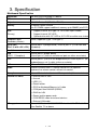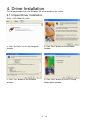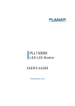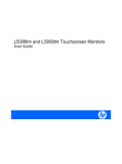
1
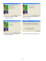
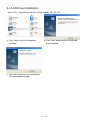
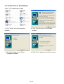
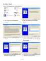
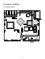
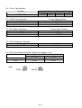
Mini kiosk K810
Price Check
Installation Guide
P/N: 48200250
June 2004 V1.0
Index
Safety ................................................................................................................... 3
1. Accessory ........................................................................................................ 4
2. I/O Function ..................................................................................................... 5
2.1 Front View................................................................................................ 5
2.2 Side View ................................................................................................. 5
2.3 Rear View ................................................................................................ 6
3. Specification..................................................................................................... 7
4. Driver Installation ............................................................................................. 9
4.1 Chipset Driver Installation........................................................................ 9
4.2 LAN Driver Installation............................................................................11
4.3 Audio Driver Installation......................................................................... 12
4.4 Elo_Touch .............................................................................................. 13
5.Jumper Setting................................................................................................ 15
5.1 B46 Mainboard ...................................................................................... 15
5.2 Bridge board .......................................................................................... 17
6.Wall Mount Bracket......................................................................................... 18
2
/19
Safety
IMPORTANT SAFETY INSTRUCTIONS
1. Read these instructions carefully.
Keep these instructions for future reference.
2. Follow all warnings and instructions marked on the product.
3. Do not use this product near water.
4. Do not place this product on an unstable cart, stand, or table.
causing serious damage to the product.
The product may fall,
5. Slots and openings in the cabinet and the back or bottom are provided for ventilation; to
ensure reliable operation of the product and to protect it from overheating, these openings
must not be blocked or covered. The openings should never be blocked by placing the
product on a bed, sofa, rug, or other similar surface. This product should never be placed
near or over a radiator or heat register, or in a built-in installation unless proper ventilation
is provided.
6. This product should be operated from the type of power indicated on the marking label. If
you are not sure of the type of power available, consult your dealer or local power
company.
7. Do not allow anything to rest on the power cord.
persons will walk on the cord.
Do not locate this product where
8. Never push objects of any kind into this product through cabinet slots as they may touch
dangerous voltage points or short out parts that could result in a fire or electric shock.
Never spill liquid of any kind on the product.
FCC
This device complies with part 15 of the FCC rules. Operation is subject to the following two
conditions:
(1) This device may not cause harmful interference.
(2) This device must accept any interference received, including interference that may cause
undesired operation.
CD-ROM Safety Warning
DANGER
INVISIBLE LASER RADIATION WHEN OPEN.
AVOID EXPOSURE TO BEAM
Caution on Lithium Batteries
Danger will explosion if battery is incorrectly replaced. Replace only with the same or
equivalent type recommended by the manufacturer. Dispose of used batteries according to
the manufacturer’s instructions.
3
/19
1. Accessory
a. Warranty Card
b. Driver bank
c. Installation Guide
The following files in the folders of Driver Bank are necessary for driver installation or manual
reference.
B46 Mainboard
Folder/File
File Description
<CD>:\B46\B46.htm
B46 Driver list
<CD>:\B46\Audio\V4.50b
Audio driver
<CD>:\Common\LAN_drive\ R8139_810x
LAN driver
<CD>:\B46\VIA4IN1
Chipset driver
<CD>:\B46\VGA
VGA driver
<CD>:\Common\Elo_Touch
Touch driver
<CD>:\datasheet\Kiosk
K810-PC installation guide
<CD>:\ Datasheet\Kiosk Peripherals\
Scanner\K810_PC
Scanner user’s manual
4
/19
2. I/O Function
2.1 Front View
1
2
#
Function
1
Magnetic Card Reader
2
Laser Scanner
2.2 Side View
Door Lock
Door Open
11
9
3
4
7
5
12
10
8
6
#
Function
#
Function
3
CD-ROM/CD Combo
8
LAN
4
Door Lock
9
Line out
5
Power Button
10
COM1
6
DC 19V IN
11
MIC input
7
USB (1.1)
12
5
/19
PS/2 (Keyboard/Mouse)
2.3 Rear View
2
1
#
Function
1
AC Inlet
2
LAN
Note: If you want to use LAN port on rear view, you have to connect a extend line from LAN
port on side view. Or you can use LAN port on side view directly.
6
/19
3. Specification
Mainboard Specification
Mainboard
B46 with exclusive bridge I/O board
CPU
Support VIA Eden 733MHz
Chipsets
VIA 8606 Twister-T (VT8606+VT686B)
Memory
On-board 128MB SDRAM
One SO-DIMM support additional memory up to 256MB (w/o ECC)
HDD
(Primary)
Compact Flash
(Secondary Master)
Socket supported (Type 1 and type 2)
Support internal Slim type 2.5” HDD from 44pin header;
Support internal 3.5” HDD
Optional drive with 2.5” HDD or 3.5” HDD are either one choice
Serial Port
Internal port x 3 (bridge board); External port x1 (D-sub from B46
(Pin 1/ 9 with +5V/+12V) Mainboard)
Parallel
N/A
USB
(USB 1.1 Compliant)
Internal port x2 (bridge board)
External port x1 (internal and external port are either one choice)
PS/2
Internal port x1 (CN14 on the bridge board) or External port x1 (for
keyboard/mouse via Y cable) (either one choice)
LAN
10 base-T /100 base-TX RJ45 port x1 (external)
Audio
External Line-out Jack x1, volume control via s/w, optional
earphone-line volume control, without h/w control
Microphone
External Mic-in Jack x1, internal Mic-in port x1 (either one choice)
External I/O Ports
1 x External Mic-in Jack
1 x line-out
1 x USB (1.1)
1 x Power button
1 x PS/2 for Keyboard/Mouse via Y-cable
1 x COM port from B46 M/B (RS232)
1 x RJ45 for LAN
1 x Power jack for power code
1 x COM RS232 cable for external devices
1 x External LAN cable
OS support
Microsoft® Windows® 2000/XP/XP Embedded, WinCE.Net 4.2 &
Linux RedHat 7.2 or above
7
/19
LCD Panel / Touch Panel
LCD size
18bit 10.4" TFT LVDS
Touch Screen
ELO 5-wire Resistive type
Brightness
10.4”: 150 ~ 230 cd/m2 (not adjustable)
Resolution
800 x 600
System / Housing
Speaker
1W speaker (with chamber) x2
Microphone
Internal electret condenser microphone unit: 9.83+/-0.1mmØ,
7.0+/-0.3mm depth
Screen Tilt Angle
80 º ~ 90 º
Door lock
Door Lock x1
Power Supply
ACBEL AC adaptor API3AD01: Input 100~240V, output
19V/6.3A/120W; Safety: UL, c/UL, TUV, T-Mark
EMC & Safety
FCC/CE Class A
Dimension (W x D x H) 263 x 134 x 376 mm
Temperature
0oC ~ 35oC, operating
Optional Device
Internal Optional Storage Slot-in & Slim CD-ROM/DVD-ROM/COMBO drive
Internal Wireless LAN Kit Mini PCI Wireless LAN Card with internal Antenna x2
Earphone
Headphone style
8
/19
4. Driver Installation
The follow procedures are for Windows XP, other platforms are similar.
4.1 Chipset Driver Installation
(Path: <CD>:\B46\VIA_4IN1)
a. Click "4in1443v" on the My Computer
window.
b. Click "Next" button on the welcome
window.
c. Click "Yes" button on the Readme
window.
d. Click "Next" button on the 4in1 Setup
Mode Option window.
9
/19
e. Click ”Next” button on the Setup
Component window.
f. Click “Next” button on the VIA PCI IDE
Bus Driver window.
g. Click “Next” button on the VIA_GART
AGP Driver window.
h. Click “OK” button to restart the system.
10 /19
4.2 LAN Driver Installation
(Path:<CD> :\Common\Lan_driver\ R8139_810x\9x_ME_2K_XP)
a. Click ”Setup” on the My computer
windows.
b. Click "Next" button on the InstallShield
Wizard window.
c. Click "Next" button on the InstallShield
Wizard complete window.
11 /19
4.3 Audio Driver Installation
(Path: <CD>:\B46\Audio\V4.50b)
a. Click ”Setup” on the My computer
windows.
b. Click "Next" button on the welcome
window.
c. Click "Next" button on the Select
Component window.
d. Click ”Finish” button to restart the system.
12 /19
4.4 Elo_Touch
(Path:<CD>:\Common\Elo_Touch\EloWinXP)
a. Click ”Setup” on the My computer
windows.
b. Click "Next" button on the welcome
window.
c. Click “Yes” on the License Agreement
window.
d. Choose “COM4” and click ”Next” button
on the Elo MonitorMouse for Windows XP
Setup window.
f. Click “Next” on the Elo MonitorMouse for
Windows XP Setup window.
g. Click “Finish” on the Elo MonitorMouse for
Windows XP Setup window.
13 /19
h. Click “Yes” on the System Settings
Change window.
i. After the computer restarted, touch the
targets with your finger for alignment.
j. Click “Yes” on the Check Video Alignment
window.
k. Click “Finish” on the “Elo TouchSystem
Setup window.
l. If the cursor is not in sync with your finger
tip, click “Align…” to execute the
alignment procedure again, or click “OK”
m. Now the Elo_Touch driver is installed.
14 /19
5.Jumper Setting
5.1 B46 Mainboard
15 /19
5.1.1 Panel Type Selection
Function
1-2
3-4
OPEN SHORT
TFT LVDS
5.1.2 CMOS Clear Selection
Function
* Normal
Clear
JP3
5-6
SHORT
* Factory Default Setting
JP5 (SHORT)
1-2
2-3
5.1.3 DIO Address Selection
Function
* 206H
386H
* Factory Default Setting
JP6
OPEN
SHORT
5.1.4 Panel Brightness Selection
Function
TFT
JP8 (SHORT)
1-2
5.1.5 PS/2 Card Reader Selection (Add-on Card Reader or not)
Function
JP9
1-2
3-4
Not exist
SHORT
SHORT
*Exist
OPEN
OPEN
Note:
OPEN
7-8
SHORT
SHORT
16 /19
5.2 Bridge board
Share With
M/B COM1
MIC In
COM1 COM2 COM3
Line Out
JP1
JP2
JP3
PS/2
USB2
USB1
(Either one)
* Factory default
JP1 (SHORT)
* 1-2
3-4
* 5-6
7-8
* 9-10
11-12
All OPEN
5.2.1COM port voltage
Function
COM1 (+5V)
COM1 (+12V)
COM2 (+5V)
COM2 (+12V)
COM3 (+5V)
COM3 (+12V)
No use
5.2.2 PS/2 Card reader
Function
1-2
Short
Open
Not Exist
Exist
5.2.3 LCD brightness
Function
Setup from M/B
MAX
JP3 (SHORT)
1-2
* 2-3
Note:
OPEN
JP2
SHORT
17 /19
3-4
Short
Open
6.Wall Mount Bracket
Step 1.Remove bracket of Kiosk
Step2. Paste the wall mount bracket install paper on the wall. And Dip four holes according to
VESA standard.(75mmx75mm or 100mmx100mm)
18 /19
Step3. Insert wall mount screws into hole. And put the wall mount bracket on the wall.
Step4 (Choose 1): Cable is through the hole of the wall
(1) Dip one hole in the bottom right corner, the size base on the wall mount
bracket install paper.
(2) Pull LAN and power cable through the hole of the wall.
Step4 (Choose 2): Cable is through the hole of Kiosk
(1). Cut the plastic on the hole of the Kiosk case.
(2). Pull LAN and power cable through the hole.
Step5. Mount the kiosk on the wall.
Step6. Open the door and secure the screw.
19 /19