1
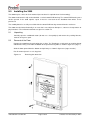
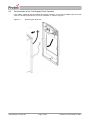
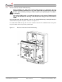
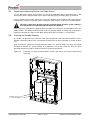
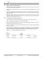
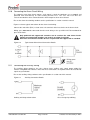
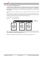
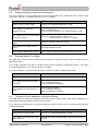
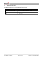
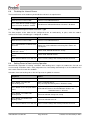
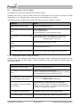
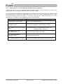
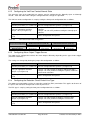
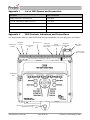
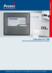
3500 CONVENTIONAL FIRE
ALARM CONTROL PANEL
INSTALLATION AND COMMISSIONING
MANUAL
Protec Fire Detection PLC, Protec House, Churchill Way, Nelson, Lancashire, BB9 6RT.
Telephone:
Fax:
Web:
Email:
+44 (0) 1282 717171
+44 (0) 1282 717273
www.protec.co.uk
[email protected]
Document Revision Details
Issue
Issue 0
Issue 1
Issue 2
Issue 3
Issue 4
Modification Detail
Document Creation
Refer to ECN3503
Refer to ECN3549
Refer to ECN3615
Refer to ECN3715
N93-586-84 Issue 04 AB
Author
AB
AB
AB
AB
AB
Page 2 of 32
Date
22/11/2013
14/05/2014
05/08/2014
01/12/2014
07/04/2015
© Protec Fire Detection plc 2015
Table of Contents
IMPORTANT NOTES – PLEASE READ CAREFULLY ................................................................................. 4
1.0
ITEMS SUPPLIED WITH THE 3500 ...................................................................................................... 5
2.0
INTRODUCTION AND KEY FEATURES .............................................................................................. 5
3.0
3500 GENERAL CABLING REQUIREMENTS...................................................................................... 6
3.1
3.2
3.3
3.4
Zone, Alarm and Auxiliary Circuit Wiring .................................................................................... 6
Alarm Circuit Wiring .................................................................................................................... 6
Mains Input Rating Label ............................................................................................................ 6
Mains Wiring ............................................................................................................................... 6
4.0
INSULATION TESTING OF CABLING PRIOR TO CONNECTION ...................................................... 7
5.0
INSTALLING THE 3500 ......................................................................................................................... 8
5.1
5.2
5.3
5.4
5.5
5.6
5.7
5.8
5.9
5.10
5.11
5.12
5.13
5.14
5.15
6.0
COMMISSIONING THE 3500 ............................................................................................................... 18
6.1
6.2
6.3
6.4
6.5
6.6
6.7
6.8
6.9
6.10
6.11
6.12
6.13
6.14
7.0
Unpacking ................................................................................................................................... 8
Removal of the Door ................................................................................................................... 8
Removal of the Control PCB Housing ...................................................................................... 10
Preparing the Mounting Position and Cable Entries................................................................. 11
Installing the Standby Batteries ................................................................................................ 11
Connecting the Standby Batteries ............................................................................................ 12
Refitting the Control PCB Housing ........................................................................................... 13
Connecting the Detection Zone Wiring ..................................................................................... 13
Connecting the Alarm Circuit Wiring ........................................................................................ 14
Connecting the Auxiliary Wiring................................................................................................ 14
Connecting the 3500 Repeat Panel ......................................................................................... 15
Connecting the Mains Cabling.................................................................................................. 16
Connecting the Fire Brigade Panel Controller .......................................................................... 16
Re-fitting the Door .................................................................................................................... 17
Switching the Mains Power On................................................................................................. 17
Access Levels ........................................................................................................................... 18
Programming Zone and Alarm Disablements .......................................................................... 20
Enabling Weekly Test Mode ..................................................................................................... 20
Testing the Panel Indications and Internal Buzzer ................................................................... 20
Clearing System Faults ............................................................................................................ 21
Disabling the Internal Buzzer.................................................................................................... 22
Programming the Alarm Activation Type .................................................................................. 22
Setting Zones to Non-Latching Operation ................................................................................ 22
Setting Zones into Test Mode................................................................................................... 23
Delaying the Alarm Output Activation ....................................................................................... 23
Setting Zones into Coincidence (Double Knock) Operation ..................................................... 24
Configuring the Volt Free Contact Normal State ...................................................................... 25
Configuring Alarm Output Trigger Source ................................................................................ 25
Configuring the Detection Circuit End of Line Type ................................................................. 25
3500 TECHNICAL SPECIFICATION ................................................................................................... 26
APPENDIX 1
LIST OF 3500 SPARES AND ACCESSORIES ................................................................. 28
APPENDIX 2
3500 CONTROLS, INDICATIONS AND CONNECTIONS ................................................ 28
N93-586-84 Issue 04 AB
Page 3 of 32
© Protec Fire Detection plc 2015
Important Notes – PLEASE READ CAREFULLY
•
Both the 3500 user manual and this manual should be thoroughly read and understood before
installation and commissioning is undertaken.
•
The 3500 and its associated connections must be installed, commissioned and maintained by a
suitably trained, skilled and competent person.
•
It is assumed that the person commissioning the system is aware of Protec Fire Detection
equipment terminology and terms of reference.
•
This equipment must be earthed and earth continuity must be preserved on broken segments of
screened cable used anywhere in the system installation.
•
This equipment is not guaranteed unless installed and commissioned in accordance with
current national standards.
•
This equipment is not suitable as part of an I.T type power distribution system as defined in
IEC60364-3.
•
It is perfectly normal for sealed lead acid batteries to vent small amounts of hydrogen when
being charged. The 3500 is vented to dissipate any build up of hydrogen. The 3500 enclosure
must not be sealed in any way.
•
A competent person trained to undertake such work MUST carry out any internal maintenance.
There are no user serviceable parts inside the 3500. Opening the PCB housing will immediately
invalidate the warranty.
0086
Protec Fire Detection plc, Nelson, Lancashire, England BB9 6RT
13
PFD-CPR-0075 3502 Fire Alarm Control Panel
PFD-CPR-0076 3504 Fire Alarm Control Panel
PFD-CPR-0077 3508 Fire Alarm Control Panel
BS EN 54-2:1997+A1:2006
BS EN 54-4:1997 + A1 + A2:2006
Control / Indicating and Power Supply equipment for fire
detection and fire alarm systems for buildings
3500 Fire Alarm Control Panel
Control & Indicating:
Performance under fire conditions: Pass
Response delay (response time to fire): Pass
Operational reliability: Pass
Durability of operational reliability, Temperature resistance: Pass
Durability of operational reliability, Vibration resistance: Pass
Durability of operational reliability, Electrical stability: Pass
Durability of operational reliability, Humidity resistance: Pass
Power supply:
Performance of power supply: Pass
Durability of operational reliability, Temperature resistance: Pass
Durability of operational reliability, Vibration resistance: Pass
Durability of operational reliability, Electrical stability: Pass
Durability of operational reliability, Humidity resistance: Pass
The policy of Protec Fire Detection plc is one of continuous improvement and as such we reserve the right to
make changes to product specifications at any time and without prior notice. Errors and omissions excepted.
N93-586-84 Issue 04 AB
Page 4 of 32
© Protec Fire Detection plc 2015
1.0
Items Supplied with the 3500
•
•
•
2.0
User manual
Installation and commissioning manual (this manual)
3500 spares kit
Introduction and Key Features
The 3500 is a conventional fire alarm control panel available in 2, 4 and 8 zone models. The 3500
incorporates an integrated power supply, two fully monitored alarm circuits and a facility for an optional
repeat panel connection.
The 3500 includes many programming and configuration features making it easy to integrate to a variety of
site conditions. The 3500 is primarily designed to drive Protec 3000PLUS detection devices.
The 3500 has been designed and manufactured in the United Kingdom and complies fully with current
standards dictating fire alarm system design practice (EN54 parts 2 and 4).
The integrity and reliability of a fire alarm system is paramount and consequently the 3500 continually
monitors all critical paths for faults. The fire detection zones and wiring are constantly monitored to check for
faults. The integrated power supply regularly performs self-checks to ensure it is fully working and that the
stand-by batteries are in a good state.
Any alarms or faults detected are reported clearly on the front panel display.
Key Features
•
2, 4 or 8 detection zones available
•
Two fully monitored conventional alarm outputs rated at 400mA per circuit
•
Integrated on-board power supply
•
Internal standby batteries
•
Attractive enclosure
•
Comprehensive range of engineering functions, including
Programmable zone disablements
Programmable alarm output disablement
Programmable non latching zone operation
Programmable coincidence zone operation
Programmable output delay per alarm (0 to 10 minutes, in 1 minute steps)
Weekly test feature
Zonal walk test feature
Pulsing or continuous alarm output activation
Manual or automatic detection alarm output activation
•
Keypad user code or fireman's key-switch access options (correct model must be ordered)
•
Ability to distinguish if a zone activation is from an automatic detector, or a Manual Call Point
•
Class Change input
•
Global fault and fire Volt free contacts
•
UK designed and manufactured
Note 1
Note 1: The MCP must contain a series 180Ω resistor for this feature to operate.
N93-586-84 Issue 04 AB
Page 5 of 32
© Protec Fire Detection plc 2015
3.0
3500 General Cabling Requirements
3.1
Zone, Alarm and Auxiliary Circuit Wiring
All wiring associated with the system must conform to the current I.E.E Regulations, and cabling
must conform to the relevant BS specifications. ECA recommended cable separation for
electromagnetic compatibility in buildings must be followed.
To comply with EMC regulations Protec recommends the use of screened cabling throughout the
installation. Where screened cables are used it is important to ensure that screen continuity is
maintained between cable segments. Any screen wiring in the 3500 panel enclosure must be
sleeved and securely bonded to the earth terminals provided.
For further information on cables, wiring and other interconnections please consult clause 26 of
BS5839 part 1.
3.2
Alarm Circuit Wiring
Two alarm circuits are provided on the 3500. Each alarm output can provide 400mA of current and
must be terminated with the correct value end of line resistor, even if the alarm output is not used.
The gauge of the alarm circuit wiring must be chosen such that the volt drop along the wiring does
not exceed specified limits. The maximum wiring resistance may be calculated using the following
formula.
Rwiring_max = (20.5 – Vdevice min) / (Idevice max)
Where Rwiring_max is the maximum resistance of the alarm circuit wiring ( both conductors )
Vdevice min is the minimum Voltage the alarm circuit devices are specified to work down to
Idevice max is the maximum total current that will be drawn on the alarm circuit
For example, if alarm devices are specified to work to a minimum of 16V and the maximum alarm
circuit current is 80mA, the maximum alarm cable resistance is 56.25Ω ( 28.13Ω per conductor ).
All devices connected to the alarm circuits must be polarised and suppressed.
Alarm devices must not be connected on spurs from the main alarm circuit wiring as
a spur will not be monitored for open circuit faults.
3.3
Mains Input Rating Label
The mains rating label is located on the inner door of the 3500 and should be consulted before
starting installation. The label details the working voltage, frequency and maximum current of the
3500.
3.4
Mains Wiring
The 3500 requires a mains supply exclusive to the panel that uses fixed three-core wiring (between
2
2
0.75mm and 2.5mm ) which is fed from a double pole isolating fused spur, fused at 3A.
Unauthorised operation of the mains supply must not be allowed and the fused spur should be
labelled “ FIRE ALARM PANEL: DO NOT SWITCH OFF ”.
Mains wiring must be segregated from all other system wiring. The wiring clamp
must be used to secure the incoming cables.
N93-586-84 Issue 04 AB
Page 6 of 32
© Protec Fire Detection plc 2015
4.0
Insulation Testing of Cabling Prior to Connection
Before connecting any external cables to any field device or the 3500, tests should be carried out using a
®‘
500V DC insulation tester (‘Megger ). If tests are performed the insulation readings between each cable
core, and each cable core and earth must be greater than 10MΩ.
The 3500 or associated devices must not be connected to any cables when high voltage
insulation tests are being performed on the cabling. The cabling must be completely
discharged prior to connection to the 3500. Equipment connected to the cabling during
insulation tests will be damaged by the high voltages used, invalidating any warranty.
N93-586-84 Issue 04 AB
Page 7 of 32
© Protec Fire Detection plc 2015
5.0
Installing the 3500
The 3500 may be surface or flush mounted (no extra bezel is required when flush mounting).
The 3500 circuit board is fully enclosed within a sealed control PCB housing. The control PCB housing must
not be opened. If the 3500 requires repair it must be sent back to the distributor from where it was
purchased.
The standby batteries are fully accessible with the control PCB housing removed from the enclosure.
The 3500 must be located internally in an area that is not subject to dampness, extremes of temperature or
physical abuse. The environmental limits are given in section 7.0
5.1
Unpacking
Carefully open the cardboard carton (do not use a sharp object) and remove the packing fitments,
manuals and spares pack.
5.2
Removal of the Door
Remove the 3500 from the packaging then, using a T15 Torx® type security tool, unscrew but do not
withdraw the fixing screw from the bottom of the panel housing front as shown in figure 5.0 (stage 1).
Slide the door upward from the bottom and pull away as shown in figure 5.0 (stages 2 and 3).
Put all removed parts in a safe, dry place.
Figure 5.0
Removing the 3500 door
N93-586-84 Issue 04 AB
Page 8 of 32
© Protec Fire Detection plc 2015
5.3
Disconnection of the Fire Brigade Panel Controller
If the 3500 is equipped with the optional fire brigade controller ensure that the ribbon cable and earth
cable are disconnected from the rear of the controller as shown in figure 5.1.
Figure 5.1
Removing the 3500 door
N93-586-84 Issue 04 AB
Page 9 of 32
© Protec Fire Detection plc 2015
5.4
Removal of the Control PCB Housing
Before handling the 3500 panel control PCB housing it is important that any
operatives discharge themselves of any static charge that may have built up. This can
be done by momentarily touching a solid earth point (a non-painted part of a radiator,
for example).
The Control PCB housing is a sealed unit and must not be opened. Tampering with
this unit will invalidate the warranty. If the unit becomes faulty it must be returned for
repair.
Unscrew and remove the four mounting screws on the control PCB housing. Carefully lift away the
control PCB housing from the plastic enclosure. See figure 5.2.
The 3500 control PCB housing and all screws should be stored in the cardboard carton away from
the place of work where they will not get damaged.
Figure 5.2
Removal of the 3500 Control PCB Housing
N93-586-84 Issue 04 AB
Page 10 of 32
© Protec Fire Detection plc 2015
5.5
Preparing the Mounting Position and Cable Entries
Use the dimensions shown on the interior rear face of the 3500 back-box in conjunction with a spirit
level to mark out the fixing locations for the panel. Drill and plug the mounting holes just marked.
Using a suitable tool carefully remove the rear panel knockouts at the required cable entry positions
and mount the enclosure in position, whilst feeding the cables into the enclosure via suitable glands.
The mains cable entry position must be segregated from all other system cabling, a
reserved knock-out is provided specifically for this purpose.
A four way brass earth block is supplied within the 3500. Three locations are provided for this in the
3500 back-box. This allows the best location to be selected depending on wiring entry requirements.
Choose the location then clip the earth block into the back-box, ensuring it is securely fitted.
5.6
Installing the Standby Batteries
The 3500 is designed to house two 12V 3.3Ah Valve Regulated Lead Acid (VRLA) batteries. These
fit into the back-box and must be secured with the two plastic tie-wraps provided (as shown in figure
5.3).
Only use batteries supplied or recommended by Protec. The internal charger has been specifically
designed to maintain the charge voltage at an optimum level for these batteries over the entire
operating temperature range in order to maximise the life of the batteries.
Figure 5.3
Installation of 3500 standby batteries (shown with the lid and control PCB housing
removed)
Tie-Wraps must be used
to secure the batteries
N93-586-84 Issue 04 AB
Page 11 of 32
© Protec Fire Detection plc 2015
5.7
Connecting the Standby Batteries
The two standby batteries must be connected in series with the battery link provided. Observing
correct polarity (red lead to the positive of one battery and black lead to the negative of the other
battery) carefully push the spade connectors of the 3500 battery leads onto the battery terminals
(illustrated in figure 5.4).
Please note that at this point the 3500 will not power up until the mains supply is connected.
Figure 5.4
Standby battery connections
BLACK battery lead
RED battery lead
Observe polarity when
connecting the battery leads
N93-586-84 Issue 04 AB
Page 12 of 32
© Protec Fire Detection plc 2015
5.8
Refitting the Control PCB Housing
Ensure that all cable earth connections are sleeved to insulate them and then securely connect them
to the brass earth terminals in the back-box.
Carefully route the battery leads (from the rear of the control PCB housing) down between the two
batteries.
If the 3500 is equipped with a fire brigade panel controller, ensure the ribbon cable connected to the
back of the control PCB housing is located over the top of the control PCB housing when refitting
into the back-box.
Replace the control PCB housing (a reversal of removal), ensuring it is pushed flush to the back-box
and that the battery leads do not get trapped. Secure with the four screws removed previously,
taking care not to over tighten the screws.
5.9
Connecting the Detection Zone Wiring
Ensure the detection circuit wiring conforms to the specifications in section 7.0 of this manual.
Figure 5.5 shows typical connections for the detection zone wiring.
Connect the end of line (EOL) device (resistor or capacitor depending on requirements) across the
terminals of the last device on the zone circuit.
Wiring spurs must not be connected from the main zone wiring as the spur WILL NOT be monitored
for open circuit faults.
To ensure compliance with BS5839 part 1 each detector base must include a series low voltage drop
diode. This ensures that Manual Call Points following a removed detector still function correctly.
Protec 3000PLUS/BASE and 3000PLUS/FFBASE products incorporate the diode as standard.
Figure 5.5
Typical 3500 Detection Zone Connection
N93-586-84 Issue 04 AB
Page 13 of 32
© Protec Fire Detection plc 2015
5.10
Connecting the Alarm Circuit Wiring
The 3500 has two alarm circuit outputs, each output is rated for continuous use at 400mA and
protected from over-load by an auto resetting thermal ‘fuse’. The ‘fuse’ will reset when the
cause of overload has been removed and the alarm output has been de-activated.
Ensure the alarm circuit wiring conforms to the specifications in section 7.0 of this manual.
Figure 5.6 shows typical connections for the alarm circuit wiring.
Connect the end of line (EOL) resistor across the terminals of the last device on the alarm circuit.
Wiring spurs must not be connected from the main wiring as the spur WILL NOT be monitored for
open circuit faults.
Only polarised and suppressed sounders can be used on the 3500 alarm circuits.
Failure to use polarised sounders can result in an alarm circuit fault.
All Protec conventional sounder devices are polarised and suppressed as standard.
Figure 5.6
5.11
Typical 3500 Alarm Circuit Connection Details
Connecting the Auxiliary Wiring
The auxiliary wiring comprises the class change input, auxiliary 24V supply output, global fire
contacts and global fault contacts. Note that these connections are optional and if not used do not
require any termination.
Ensure the auxiliary wiring conforms to the specifications in section 7.0 of this manual.
Figure 5.7
Auxiliary Connection Details
Auxiliary 24V Output Connection
N93-586-84 Issue 04 AB
Class Change Input Wiring
Page 14 of 32
© Protec Fire Detection plc 2015
5.12
Connecting the 3500 Repeat Panel
The 3500 can support additional repeat panels allowing the state of the system to be monitored from
alternative locations. The 3500 control panel can support up to 5 3500 repeat panels, supplied from
the auxiliary 24V supply output or up to 10 3500 repeat panels, supplied from an external EN54-4
power supply unit. The connections for the repeat panel are optional and if not used do not require
any termination.
The 3500 repeat panel is mounted using the same process followed for mounting a 3500 control
panel.
Ensure that the correct polarity is observed when wiring the 24V supply to the 3500 repeat panel.
The RS485 is connected from the A terminal of the host panel to the A terminal of the repeat panel
and the B terminal of the host panel to the B terminal of the repeat panel.
The connections are shown in figure 5.8
Figure 5.8
Typical wiring diagram
To further
repeat panels
When carrying out commissioning of the 3500 control panel ensure that the 3500 repeat panels
mimic the display of the 3500. Ensure that if the if the repeat panel is locally muted, the buzzer
resounds upon the activation of an additional fault or fire.
For further details regarding a 3500 repeat panel refer to DEL2129, supplied with the unit.
N93-586-84 Issue 04 AB
Page 15 of 32
© Protec Fire Detection plc 2015
5.13
Connecting the Mains Cabling
Isolate the incoming mains supply by ensuring the fused double pole isolator is in the
‘OFF’ position.
Pay particular attention that the incoming mains cable is segregated from all other
cables within the 3500 enclosure.
Ensure the incoming earth cable is firmly connected to the Main PCB (see figure
5.9) and the earth cable from the Main PCB is securely connected to the brass earth terminals
within the back-box.
The mains wiring must now be restrained using the clamp provided to secure the mains
cables to the control PCB housing (see figure 5.10). The restraining clamp must be supported
at the rear when the two screws are being tightened.
Figure 5.9
Power Supply Terminal Details
Figure 5.10
Mains wiring connections
Main PCB to earth
block cable
Mains wiring
clamp
N93-586-84 Issue 04 AB
Page 16 of 32
© Protec Fire Detection plc 2015
5.14
Connecting the Fire Brigade Panel Controller
If the 3500 is equipped with the optional fire brigade controller ensure that the ribbon cable and earth
lead are re-connected to the rear of the controller as shown in figure 5.11.
Figure 5.11
5.15
Reconnecting the Fire Brigade Panel Controller
Re-fitting the Door
Before replacing the door ensure all mains, zone, alarm and auxiliary wiring has been completed and
will not foul the door when it is refitted.
Replace the plastic door by raising the door and placing flush to the back-box of the panel (figure
5.12 step 1). Slide the door down and ensure it pushes fully home into the back-box (figure 5.12 step
2). Finally screw in the fixing screw, taking care not to over tighten the screw (figure 5.12 step 3)
Figure 5.12
5.16
Refitting the 3500 door
Switching the Mains Power On
Switch the fused isolator to the ‘ON’ position.
The green ‘Power’ indicator will illuminate, the 3500 is now ready to be programmed and
commissioned.
N93-586-84 Issue 04 AB
Page 17 of 32
© Protec Fire Detection plc 2015
6.0
Commissioning the 3500
The 3500 has many programmable features, making it extremely flexible. These can be accessed by users
at different authorisation levels. The features available at the different authorisation levels are detailed below.
6.1
Access Levels
Access Level 1 (User code not entered)
The panel’s front panel display indicators are visible, providing a clear status of the 3500 at that time.
The functions that may be performed at access level 1 are:
•
Entry of the 6 digit user code to access level 2 or level 3 functions
•
Activation of the front panel fireman's key-switch (correct model must be ordered)
Access Level 2 (User code entered, or fireman's key-switch activated)
Only authorised users are permitted access to level 2 functions, these are:
•
Accepting the current state of the panel and Mute the panel’s internal buzzer
•
Silencing an alarm condition
•
Resetting the panel after silencing an alarm activation
•
Sounding the alarms
•
Disablement of detector circuits
•
Disablement of alarm circuits
•
Programming weekly test mode (all zones in walk test mode)
•
Testing the front panel indications and internal buzzer
•
Clearing of system faults
Access Level 3 (Engineer Controls)
Only engineers are permitted access to level 3 functions, these are:
•
Silencing an alarm condition
•
Resetting the panel after an alarm activation
•
Disablement of the internal buzzer
•
Programming pulsing or continuous alarm activation
•
Programming of non-latching zones
•
Programming of test zones (one, or more zones may be programmed)
•
Programming of output delays
•
Programming of coincidence zones
N93-586-84 Issue 04 AB
Page 18 of 32
© Protec Fire Detection plc 2015
Access Level 4 (3500 cover removed, tool required)
•
Configuration of global fire relay contact state (normally closed or normally open)
•
Configuration of global fault relay contact state (normally closed or normally open)
•
Configuration of alarm output activation type
•
Global configuration of End of Line type (capacitive or resistive)
Configuration of panel at access level 4 is carried out using the locations of 4 links, accessible with the panel
door removed, shown in figure 6.0. (see appendix 2)
Figure 6.0 – Panel Configuration Links
ON
OFF
1
2
3
4
Jumper
1
2
3
4
Feature
Configure Aux Fault Relay Contacts
Configure Aux Fire Relay Contacts
Configure Sounder Activation
ON
Normally Closed
Normally Closed
Global
Configure Zone EOL
N93-586-84 Issue 04 AB
Capacitive
Page 19 of 32
OFF
Normally Open
Normally Open
Sounder 1 = Call Point
Sounder 2 = Detector
Resistive
© Protec Fire Detection plc 2015
6.2
Programming Zone and Alarm Disablements
This menu allows the user to disable any or all of the detection zones and/or both of the alarm circuits
(activations and faults are inhibited when the circuit is disabled).
6.3
Sequence
Effect
Enter the access level 2 code
'Access Level' indicator illuminates steady
Press button '1' to enter the
disablement menu
'Disablement' indicator flashes
Zone 1 indicator flashes
Any currently disabled zones or alarms illuminate steady
Press button '2' or '3' to cycle round
disablement choices
Cycles through disablement choices, selected choice
flashes the relevant indicator. Choices are:
Individual zones -> all zones -> alarms
Press button '1' to disable current
choice
Relevant indicator changes to steady
Press button '4' to enable current
choice
Relevant indicator turns off
Press 'Enter' button to save and exit
Saves current settings into memory and exits the menu
Enabling Weekly Test Mode
The 3500 allows all zones to be programmed into weekly test mode, this permits rapid verification of device
operation on zones.
In this mode, activations from zones sound the alarms for 10 seconds for verification purposes, after which
the 3500 automatically resets and exits weekly test mode.
If no zone activations are detected for 10 minutes, weekly test mode is automatically exited.
6.4
Sequence
Effect
Enter the access level 2 code
'Access Level' indicator illuminates steady
Press button '2' to activate weekly
test mode
Activates weekly test mode
‘Test’ indicator illuminates
Zone test indicators illuminate
Press button '2' to exit weekly test
mode
Exits weekly test mode
‘Test’ indicator extinguishes
Zone test indicators extinguish
Testing the Panel Indications and Internal Buzzer
The 3500 allows the front panel indications and internal buzzer to be tested. In this mode all indicators are
momentarily illuminated and the internal buzzer sounded.
If any indicators fail to illuminate, or the buzzer does not sound, note this in the system log and get the fault
rectified immediately.
Sequence
Effect
Enter the access level 2 code
'Access Level' indicator illuminates steady
Press button '3' to activate the lamp
and buzzer test
All indicators momentarily illuminate and the internal buzzer
sounds
N93-586-84 Issue 04 AB
Page 20 of 32
© Protec Fire Detection plc 2015
6.5
Clearing System Faults
In general faults on the 3500 are non-latching and will clear automatically when the fault is rectified. Some
faults however are latched on the system and require clearing manually.
Sequence
Effect
Enter the access level 2 code
'Access Level' indicator illuminates steady
Press button '4' to clear any latched
faults
Any latched faults are cleared. If the fault remains it will be
re-generated.
N93-586-84 Issue 04 AB
Page 21 of 32
© Protec Fire Detection plc 2015
6.6
Disabling the Internal Buzzer
The internal buzzer of the 3500 may be disabled to suit local site requirements.
6.7
Sequence
Effect
Enter the access level 3 code
'Access Level' indicator flashes
Press 'Mute Buzzer' button to toggle
between buzzer disabled / enabled
‘Disablement’ indicator illuminates if buzzer is disabled
Programming the Alarm Activation Type
The alarm outputs of the 3500 can be configured to turn on continuously, or pulse, when the 3500 is
activated. The alarm activation type is configured as follows.
6.8
Sequence
Effect
Enter the access level 3 code
'Access Level' indicator flashes
Press ‘Sound Alarms’ button to enter
the menu
The ‘Alarm Fault’ indicator will illuminate steady if the
alarms are set to continuous or flashing if the alarms are
set to pulse.
Press button '1' to program
continuous alarms
‘Alarm Fault’ indicator illuminates steady
Press button '4' to program pulsing
alarms
‘Alarm Fault’ indicator flashes
Press 'Enter' button to save and exit
Saves current settings into memory and exits the menu
Setting Zones to Non-Latching Operation
Standard zone operation is latching, activations from latching zones require the 3500 to be silenced and
reset manually. Activations from a zone programmed as non-latching automatically reset the 3500 when the
zone returns from fire to non-fire condition.
Activations from non-latching zones DO NOT operate the global fire contacts.
Sequence
Effect
Enter the access level 3 code
'Access Level' indicator flashes
Press button '1' to enter the
non-latching menu
Zone 1 indicator flashes
Any currently non-latching zones illuminate steady
Press button '2' or '3' to cycle round
zones
Cycles through zones to be programmed into non-latching.
Selected zone flashes relevant indicator. Choices are:
Individual zones -> all zones
Press button '1' to enable nonlatching mode
Relevant indicator changes to steady
Press button '4' to disable nonlatching mode
Relevant indicator turns off
Press 'Enter' button to save and exit
Saves current settings into memory and exits the menu
N93-586-84 Issue 04 AB
Page 22 of 32
© Protec Fire Detection plc 2015
6.9
Setting Zones into Test Mode
The 3500 permits zones to be programmed into walk test mode.
Activations from zones in walk test mode activate the alarm outputs for 10 seconds, after which the 3500
automatically resets. Activations from a zone not in test mode will operate as normal.
Activations from zones programmed as walk test DO NOT operate the global fire contacts.
Sequence
Effect
Enter the access level 3 code
'Access Level' indicator flashes
Press button '2' to enter the walk test
menu
‘Test’ indicator flashes
Zone 1 indicator flashes
Any current walk test zones illuminate steady
Press buttons '2' or '3' to cycle round
zones
Cycles through zones to be programmed into walk test.
Selected zone flashes relevant indicator. Choices are:
Individual zones -> all zones
Press button '1' to enable walk test
mode
Relevant indicator changes to steady
Press button '4' to disable walk test
mode
Relevant indicator turns off
Press 'Enter' button to save and exit
Saves current settings into memory and exits the menu
6.10
Delaying the Alarm Output Activation
An output delay may be programmed if required. In this mode a delay is introduced from detection of a zone
activation to activating the alarm outputs. The delay DOES NOT apply to the global fire contacts which will
operate immediately.
Sequence
Effect
Enter the access level 3 code
'Access Level' indicator flashes
Press button '3' to enter the delays
menu
'Outputs Delayed' indicator illuminates
Zone 1 indicator flashes to show Alarm output 1 is selected
Any currently delayed alarms illuminate steady
Press button '2' or '3' to cycle round
the alarm outputs to be delayed
Cycles through delay choices. Selected alarm flashes the
relevant zone indicator. Choices are:
Individual alarms -> all alarms
Press button '1' to increment delay
time in minutes
Repeated presses of this button increase the delay
between 1 and 10 minutes. The delay is indicated by the
number of flashes shown on the 'Outputs Delayed' indicator
(5 flashes = 5 minutes, for example)
Press button '4' to disable delays
Disables the delay on the selected alarm outputs
Press 'Enter' button to save and exit
Saves current settings into memory and exits the menu
N93-586-84 Issue 04 AB
Page 23 of 32
© Protec Fire Detection plc 2015
6.11
Setting Zones into Coincidence (Double Knock) Operation
Two or more zones may be programmed into coincidence groups. In this mode two or more of the
programmed zones must trigger in order to activate the alarm outputs.
If only one zone in the coincidence group triggers, the 3500 will flash the relevant zone fire indicator, sound
the internal buzzer and activate the global fire contacts. The user may then investigate the cause of the
alarm and manually activate the alarms in necessary. Operation of a Manual Call Point on a zone
programmed as coincidence will immediately activate the alarm outputs.
Sequence
Effect
Enter the access level 3 code
'Access Level' indicator flashes
Press button '4' to enter the
coincidence menu
Zone 1 indicator flashes
Any currently coincidence zones illuminate steady
Press button '2' or '3' to cycle round
zones
Cycles through zones to be programmed into coincidence.
Selected zone flashes relevant indicator. Choices are:
Individual zones -> all zones
Press button '1' to enable
coincidence mode
Relevant indicator changes to steady
Press button '4' to disable
coincidence mode
Relevant indicator turns off
Press 'Enter' button to save and exit
Saves current settings into memory and exits the menu
N93-586-84 Issue 04 AB
Page 24 of 32
© Protec Fire Detection plc 2015
6.12
Configuring the Volt Free Contact Normal State
The quiescent state of the 3500 Volt free contacts may be configured to be 'Normally Open' or 'Normally
Closed'. Table 6.0 shows how setting the configuration links changes the operation.
The Volt free contact configuration is setup by setting the front panel configuration links as follows.
Sequence
Effect
Remove panel door (see section 5.2)
Reveals configuration link aperture (see figure 5.0)
Using an appropriate tool alter
jumper 1 or 2 (see figure 5.0)
Jumper 1 or 2 in ‘ON’ position to configure normally closed
contacts
Jumper 1 or 2 in ‘OFF’ position to configure normally open
contacts
Replace panel door (see section
5.12)
Hides configuration link aperture
Table 6.0
Aux fault contact state configuration
Global Fire Contacts (Link J2)
Global Fault Contacts (Link J1)
Normally Open
In Fire
Short Circuit
Not In Fire
Open Circuit
In Fault
Short Circuit
Not in Fault
Open Circuit
Normally Closed
Open Circuit
Short Circuit
Open Circuit
Short Circuit
Jumper Link Configuration
6.13
Configuring Alarm Output Trigger Source
The 3500 can be configured to activate the alarm outputs differently depending on the type of zone trigger
(manual or automatic).
The settings are changed by altering the jumper link configuration as follows.
Sequence
Effect
Remove panel door (see section 5.2)
Reveals configuration link aperture (see figure 5.0)
Using an appropriate tool alter
jumper 3 (see figure 5.0)
Jumper 3 in ‘ON’ position to configure global activations
Jumper 3 in ‘OFF’ position to configure separate automatic
and manual activations
Replace panel door (see section
5.12)
Hides configuration link aperture
6.14
Configuring the Detection Circuit End of Line Type
The 3500 can accommodate resistive or capacitive end of line (EOL) termination. This applies to all zones of
the panel, and cannot be configured on a zone by zone basis.
The EOL type is setup by setting the front panel configuration links as follows.
Sequence
Effect
Remove panel door (see section 5.2)
Reveals configuration link aperture (see figure 5.0)
Using an appropriate tool alter
jumper 4 (see figure 5.0)
Jumper 4 in ‘ON’ position to configure capacitive EOL
Jumper 4 in ‘OFF’ position to configure resistive EOL
Replace panel door (see section
5.12)
Hides configuration link aperture
N93-586-84 Issue 04 AB
Page 25 of 32
© Protec Fire Detection plc 2015
7.0
3500 Technical Specification
General Specification
Ambient Temperature Range
-5 to 40 degrees Celsius
Humidity Limit
95% RH (no condensation, or icing)
Environment
Meets IP30 if mounted in a dry position that does not exceed the temperature
and humidity limits given above
Mounting
3 points surface mount or flush (no extra bezel required when flush mounting)
Dimensions
228mm (W) x 345mm (H) x 111mm (D)
Standby Time
72 hours typical
(8 zones loaded with 25 3000PLUS/OP devices, 800mA alarm load for 30
minutes)
Power Supply Specification
Rated Voltage
100 to 240V ac rms
Rated Frequency
50 to 60 Hz
Rated Current
600mA rms
Maximum Inrush Current
20A at 240V from cold
452mA (22mA panel, 5mA zones, 150mA Aux 24V, 275mA battery charge)
Maximum Quiescent Load (Imax_a)
177mA (22mA panel, 5mA zones, 150mA Aux 24V)
Maximum Alarm Load (Imax_b)
1026mA (48mA panel, 28mA zones, 800mA alarm, 150mA Aux 24V)
Note: Batteries are not charged during an alarm condition
Minimum Load, Imin, panel only
22mA panel normal (30 seconds after a mains failure)
48mA panel in alarm (30 seconds after a mains failure)
Mains Input Fuse
1.6A time delay (not user or engineer replaceable)
Standby Battery Requirements
2 x 12V 3.3Ah Sealed Lead Acid (connected in series)
Only use batteries recommended by Protec (see appendix 1)
Output Voltage
24 – 29V dc with mains present , 17 – 29V dc on batteries
Deep Discharge Protection
Yes. Less than 150µA drawn from batteries (3500 is turned off)
Deep Discharge Activation Level
18.5V dc battery terminal Voltage
Output Ripple Voltage
400mV maximum (peak to peak) at full output load
Battery Charge Voltage
27.3V at 20 degrees C. Temperature compensated at
– 40mV / deg C. Protected by 1.6A self-resetting thermal 'fuse'
Battery Charge Current
250mA (± 25mA)
Battery Test Load
47Ω (internal to the 3500)
Battery Over Voltage Fault Level
28.5V dc
Battery Under Voltage Fault Level
22V dc
Battery Monitoring
Charger dip, battery load and internal impedance
Maximum Battery Resistance (Ri)
2Ω (battery internal resistance + lead and connection resistances)
Note 1
5mA comprises 8 fully loaded zones of Protec 3000PLUS/OP detectors.
N93-586-84 Issue 04 AB
Page 26 of 32
© Protec Fire Detection plc 2015
Detection circuit specifications
Number of detection zones
2 (3502), 4 (3504), 8 (3508)
Cable requirements
Fire resistant screened cable
Maximum zone wiring length
500 metres
Maximum zone wiring resistance
15Ω per conductor
Maximum zone wiring capacitance
0.25µF conductor to conductor
Resistive end of line details
8.2kΩ ±5% ¼W
Capacitive end of line module details
100µF 35V ±5% capacitor in series with a 22Ω ¼W resistor
Maximum number of detectors per zone
25 Protec 3000PLUS/OP devices
Maximum number of devices per zone
32 (combination of Manual Call Points and automatic detectors)
Manual Call Point requirements
Must be fitted with a series resistor (150Ω to 680Ω).
A 180Ω ±5% ¼W resistor must be fitted for the 3500 to distinguish between
manual and automatic triggers on zones.
Alarm circuit specifications
Number of alarm circuits
2
Maximum current per circuit
400mA
Circuit overload protection
Protected by a self-resetting thermal 'fuse'
Cable requirements
Fire resistant screened cable
Maximum circuit wiring length
500 metres
Maximum alarm circuit capacitance
0.25µF conductor to conductor
End of line monitoring type
Voltage reversal using common 0V
Resistive end of line details
10kΩ ±5% ¼W
Alarm circuit device requirements
All devices connected to the alarm outputs must be polarised and suppressed
Pulse rate when output set to 'pulsing'
Pulse rate of 2 second on and 2 second off
Auxiliary circuit specifications
Auxiliary 24V output current
150mA maximum (protected by monitored, self-resetting thermal 'fuse')
Any overload must be completely removed to clear a fault condition
Class change input
Class change triggered when CC input connected to 0V with less than 50Ω
Global fire and fault output contacts
Volt free changeover contacts rated at a maximum of 1A 24V dc (resistive)
Security codes
User security code
134422
Engineer security code
314431
N93-586-84 Issue 04 AB
Page 27 of 32
© Protec Fire Detection plc 2015
Appendix 1
List of 3500 Spares and Accessories
Description
Protec Stock Code
Standby battery inter connection lead
N 41-796-44
12V 3.3Ah VRLA battery (Online OL3.3-12)
N 13-120-24
3500 8 zone spares kit
N 62-807-SPARES
3500 user manual
N 93-571-87
3500 Installation & commissioning manual (this manual)
N 93-586-84
Appendix 2
3500 Controls, Indications and Connections
The diagram below shows the 3500 Control PCB housing and highlights the main connections and controls.
Global fire
contacts
Global fault
contacts
Detection zones
Monitored
Monitored
RS485
conventional Communications Auxiliary 24V
output
alarm outputs
Class Change
input
Mains cable
restraint
ac mains input
supply connections
Configuration
links
1
2
3
4
Firemans access level 2 keyswitch input
(Specific models only)
N93-586-84 Issue 04 AB
Page 28 of 32
© Protec Fire Detection plc 2015
N93-586-84 Issue 04 AB
Page 29 of 32
© Protec Fire Detection plc 2015
N93-586-84 Issue 04 AB
Page 30 of 32
© Protec Fire Detection plc 2015
N93-586-84 Issue 04 AB
Page 31 of 32
© Protec Fire Detection plc 2015
Protec Fire Detection PLC, Protec House, Churchill Way, Nelson, Lancashire, BB9 6RT.
Telephone:
Fax:
Web:
Email:
+44 (0) 1282 717171
+44 (0) 1282 717273
www.protec.co.uk
[email protected]
N93-586-84 Issue 04 AB
Page 32 of 32
© Protec Fire Detection plc 2015