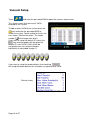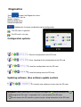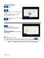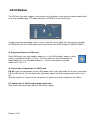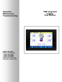
1
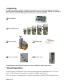
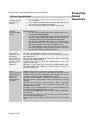
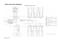
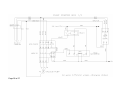
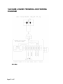
Operation
Maintenance
Troubleshooting
Instant Access
Parts and Service
+35342 9335560
+35342 9334422
www.tsmcontrols.com
[email protected]
Page 1 of 27
TSM integrated
loading
User Manual
Table of Contents.
Please read before installing the system ................................................ 3
DISCLAIMER: ........................................................................................ 4
Unpacking .............................................................................................. 7
Visual Inspection: ................................................................................... 7
Loader Dimensions. ............................................................................... 9
Principle of Operation ........................................................................... 10
Accessing the vacuum loading ............................................................. 11
Switching on/off the vacuum loaders .................................................... 11
Vacuum icons explained ...................................................................... 12
Configuring the Vacuum loaders .......................................................... 13
Configuring the Vacuum pump(s) ......................................................... 14
Diagnostics ........................................................................................... 15
Vacuum Setup ...................................................................................... 16
System menu ....................................................................................... 17
Diagnostics ........................................................................................... 18
Updating software: (See software update section) ........................... 18
System settings .................................................................................... 19
Vacuum receiver. ................................................................................. 20
VAC8 Module ....................................................................................... 21
Frequently Asked Questions ................................................................ 22
Vacuum Pump system overview .......................................................... 23
VAC8 connection diagrams .................................................................. 24
VACUUM LOADER TERMINAL BOX WIRING DIAGRAM .................. 27
Page 2 of 27
Please read before installing the system
Moving plastic granules can produce extreme static charges.
All flexible tubing conveying lines MUST contain a ground wire.
When connecting the flexible hose you can strip back a length
of ground wire and bend it inside the hose. When this is pushed
onto a metal tube the earth connection is made.
If this type of piping is not used then extra care must be taken to
ensure the vacuum loaders are properly earthed.
If pipes carrying the granules are not properly earthed, then the
electrical energy will be discharged down through the system
electronics causing possible malfunction and damage.
Generally, static symptoms include the resetting of the Remote
Display or granules sticking to the sides of the hopper or the
mixing chamber.
Therefore do not attach communications cables to material
conveying lines or other conduit containing cables with high
voltages or high currents.
We recommend using shielded cable with twisted pairs inside.
E.G. cat 5 cable. (multi strand)
If possible, run the communications lines in armoured trunking
that is properly earthed/ grounded at one end only.
Keep all communication lines well removed from vacuum loader
and/or material conveying pipes.
All flexible conveying lines MUST contain a ground wire
that is earthed at least on one end.
Earth continuity should be checked between the vacuum
loaders and the blender body. (If necessary run an earth
strap from a point on the blender frame to each loader)
ONLY SHIELDED CABLES SHOULD BE USED.
Cable shields must be properly connected at ONE end of
the cable only.
Failure to adhere to the above guidelines may void
warranty.
Page 3 of 27
It is a good idea to record the model and serial number(s) of your
equipment and the date you received it in the User Guide. Our
service department uses this information, along with the manual
number, to provide help for the specific equipment you installed.
Please keep this User Guide and all manuals, engineering prints and parts
lists together for documentation of your equipment.
Date:
Manual Number:
Serial number(s):
Model number(s):
Software version
Panel
Blender
DISCLAIMER:
TSM Control Systems Ltd. shall not be liable for
errors contained in this User Guide or for incidental, consequential
damages in connection with the furnishing, performance or use of this
information. TSM makes no warranty of any kind with regard to this
information, including, but not limited to the implied warranties of
merchantability and fitness for a particular purpose.
Copyright 2002 All rights reserved TSM Control Systems.
Page 4 of 27
Please record your equipment’s model and serial number(s),
software versions and the date you received it in the spaces
provided.
Page 5 of 27
Page 6 of 27
Unpacking
On opening, cartons should be thoroughly searched to ensure that all components have been
removed. Before proceeding, the packing note and this manual should be studied. By referring to
the Installation section the following items should be found and identified:
VAC8 Module.
Vacuum Receivers.
Vacuum pump.
Flexible Hose
Vacuum manifolds.
Suction Lance
The packing note will indicate the presence of any additional special order items.
Visual Inspection:
Visually inspect all components to ensure that no damage occurred during transit. The visual
check should include any connectors for evidence of broken or bent pins.
Any missing items or damaged parts should be immediately notified to TSM Control Systems.
Page 7 of 27
Installation & Commissioning
• Cable from Blender control module console to VAC8
Module.
These cables provide power (24V) and serial communications
to each vacuum loader control card.
Please Note:
In order to ensure system accuracy the system
cables should not run parallel to heavy power line
cables or cables supplying inductive loads. The
cables should not run through areas where high
electrostatic fields exist. If either of the above
conditions exist then it may be necessary to run the
cables through electrically screened trunking.
cables should not run parallel to material conveying
lines.
Power should not be applied to any part of the system
until authorised personnel have checked it, i.e. the
TSM commissioning engineer or a project electrician
who is competent to assemble the system.
Flexible antistatic hose.
Flexible antistatic hose with an earth wire should
only be used for connecting the vacuum loaders
to the manifold. All other piping should be
stainless steel or another suitable alternative.
When connecting the flexible hose to either the
loader or the manifold strip back 3-4 cm of the
wire and bend it inside the hose. When the hose
is pushed onto the loader/manifold the wire will make contact
with the metal surface and therefore earth the hose through the
loader/ manifold.
Page 8 of 27
Loader Dimensions.
Ø
Model
TVR–6
TVR –10
TVR –15
TVR –35
TVR –50
Capacity (ft /lt)
0.2/6
0.35/10
0.5/15
1.2/35
1.7/50
Height (“/mm)
24”/610
29.9”/760
31.1”/790
42.9”/1090
45.3”/1150
10.2”/260
10.2”/260
13”/330
13”/330
17.7”/450
17.6/8
22/10
30.9/14
39.7/18
44/20
2”/2.5” /3”
2”/2.5”/3”
2”/2.5”/3”
2”/2.5”/3” /4”
2”/2.5”/3” /4”
51/63/75
51/63/75
51/63/75
51/63/75/100
51/63/75/100
3
Diameter Ø (“/mm)
Weight (lb/kg)
Line Size
(“/ mm)
Page 9 of 27
Principle of Operation
The Blender serves as a vacuum loading control system. It
operates as a master controller, communicating serially with a
number of vacuum receiver control cards as required.
Each vacuum receiver control card has a unique address that
the Blender identifies when communicating with that vacuum
loader.
The vacuum loading screen gives the operator access to all of
the information required to setup, monitor and operate all the
loaders connected to the blender.
A password protected menu system allows supervisor access
to configuration and diagnostics information.
Page 10 of 27
Accessing the vacuum loading
If a blender is configured with
integrated loading the home screen
will display vacuum loaders on the
blender icon.
To access the loader screen simply
touch the loader icon.
Switching on/off the vacuum loaders
The loaders are arranged in banks
of 16 loaders.
To access a loader touch the bank
that it belongs to and that bank will
open.
Once a loader bank is selected,
Loaders can be Enabled/Disabled by
touching the top of each individual loader
Any loader alarms can be cleared
by touching this icon.
This icon allows you to return to
the home screen.
Page 11 of 27
Vacuum icons explained
Loader Icon
explained
Loader conditions
Pump station
Loader off
(Grey)
Loader on
Empty (Green)
(Green)
Loader Name
Pump off, AV closed, Filter off
Loader on full
Green + green
dot
Fill time
Full/Empty
Pump station
Loader empty
(Yellow)
Loader filling
(Yellow)
Loader
alarm
(Red)
Page 12 of 27
Pump on, AV open, Filter cleaning
Configuring the Vacuum loaders
Touching the centre of the loader
opens the loader setup screen
Touch the loader icon and a popup will
appear
To edit a loader setting you must unlock
the loader first. To do this touch the
icon, enter the password 9335.
The icon will then change to
allowing the loaders to be edited
You can scroll through the loaders by using the side arrows
at the top of the screen
Loader ID: This can be up to 4 characters and is entered using the Alphanumeric keyboard
(touch to the right of the loader ID to open the keyboard)
Vacuum Time: This is the filling time for the loader in seconds.
Priority: This is a very useful feature on a larger system where certain loaders need to fill more
often than others. 1 is the highest priority.
Post Fill Time: If a high level sensor is used in the loader this is the filling time after the sensor
is triggered. (Allowing the loader to fill completely)
Pump used: If there is more than one pump used a loader can be assigned to what ever pump is
needed.
Load Default Values:
Default values
Copy this loader XX from X to X: If you need to configure more than one loader and the others
loaders will have a similar configuration, you can copy the configuration from one loader to the
other loaders to save some time setting them up.
Page 13 of 27
Configuring the Vacuum pump(s)
Touch the
icon and a popup will appear
that that allows you to edit the Pump
configuration
To edit a pump setting you must unlock the
pump first. To do this touch the
the password 9335.
icon, enter
The icon will then change to
allowing the pump(s) to be edited
Pump ID: This can be up to 4 characters and is entered using the Alphanumeric keyboard (touch
to the right of the loader ID to open the keyboard)
Pump Start Time: When a loader calls for a fill the system will allow the pump this number of
seconds to start-up before commencing a loader fill.
Pump Idle Time: This is the length of time in seconds that the pump will continue running after
all of the loaders are full. This is normally set to 30 seconds to avoid
unnecessary stopping/starting of the pump.
A-Valve Overlap Time (atmosphere/ relief valve): If this time is set, then when a loader is
finished filling the AV will open for this number of seconds to lower the vacuum
in order for another loader to open its fill valve.
Dust Filter Type: None = no dust filter is installed.
TSM = A TSM dust filter is installed.
BH = dust filter output remains on continuously.
The Dust Filter blasts then becomes the no of seconds which the filter output
is activated for.
Dust Filter Blasts: This is the number of filter cleans the dust filter will perform.
VAC8IO used: This option assigns the pump control to a particular VAC8 card.
Backup Pump: If a pump develops a problem then a backup pump can be automatically
switched in as a replacement as long as it has been configured to do so.
Load Default Values:
Page 14 of 27
Default values
Diagnostics
From the home screen you can access the
Diagnostics, Vacuum Setting, and the Setup
menu.
Diagnostics
To access the diagnostics touch
icon.
When the communications are working the TX and
the RX counters should be the same value. If you
have more that 10% Err or
(timeouts) then
there is a problem with the communications (see
F.A.Q. section for trouble shooting help).
If a VAC8 card stops communicating the controller
will stop polling it continuously and will retry once
every minute. Therefore if communications to a
VAC8 board fail, that board wont slow the comms
to the other boards.
If the communications have been running for a
long period of time there may be some Err’s or
timeouts occurring over time so you should reset the counters using the
then allow the counters to run to approximately 100 counts.
icon and
The
shows which VAC8 card is controlling the pump This cannot be
changed here you must assign the VAC8 IO on the pump configuration page.
Page 15 of 27
Vacuum Setup
Touch
and enter the password 5560 to open the vacuum setup screen.
This screen shows that there are 3 VAC8
enabled on the system.
To add another VAC8 to the system touch the
icon and enter the password 9335 to
unlock the system. Touch enable for the 4th vac
8 as shown. Confirm the action. The loader
number ( ) will change from 0 to 8
If you want to setup the default ID’s touch the
icon and the loaders will be given the
default ID’s (for VAC8 5 L33 L40 will be
assigned or you can setup the loaders
individually as described in page 11.
If you want to setup the loader defaults then touching
will setup the loader defaults for all loaders assigned to that VAC8
Default values
Page 16 of 27
System menu
Touch
The system menu contains all of the options
primarily used during initial setup and before normal
operation. As all system parameters can be
changed from this menu; a password is required for
access from the Main Menu.
IMPORTANT: We recommend that you restrict
access
to
the
supervisor
password
to
supervisor/management
personnel
and
the
Engineering password to technical personnel.
(The Password are shown on page 2 of this
manual.)
From the System Menu, you can:
•
Set the time and date.
•
Set and change the passwords
•
Update the software
•
Enable the diagnostic logs/TELNET
Page 17 of 27
Diagnostics
Touch
to open the Diagnostics menu.
This menu allows you to:
Update software.
Backup configuration
Reload configuration
Updating the firmware and backing up the configuration.
The SD card is in position
The SD card is missing
Configuration options.
1. Save the configuration to the SD card.
2. Save a backup of the configuration to the SD card
3. Load the configuration from the SD card
5. Load the backup from the SD card.
Updating software: (See software update section)
6. Load the new software version from the SD card.
WARNING: Before removing the SD card you must open the
screen and touch the
Saving to the SD card is suspended so it is safe to remove the SD card
Do not remove the SD card the system may be saving information to the SD card.
Page 18 of 27
System settings
Settings.
Use this option to set the correct time, day
and date.
Touch the appropriate box on the
Line and enter the new value.
Touch the save icon to update
the time.
Passwords.
This screen can be used to change the
operator and supervisor passwords.
Operator password
This allows the operator access into the
recipe section.
Supervisor password
This allows the supervisor into the recipe section and also the system settings
.
This password should be restricted to authorised personnel as it allows access to the settings.
Note: it is important to make a note of new passwords
Page 19 of 27
Vacuum receiver.
Vacuum line
Compressed air
Material line
Local on/off switch
Full/empty read
sensor
To open the top of the loader
use these 3 clips
Filter
When replacing sections
ensure the seal is in position.
There is a location tab on the cone and this fits into the slot on the
loader body. This is important as it lines up the magnetic read
switch.
Page 20 of 27
VAC8 Module
The VAC8 as the name suggests, can connect up to 8 loaders to the vacuum control module with
an 8 core shielded cable. This cable connects to CONN14 on the VAC8 card.
In order to connect two loader cards in series, wire the comms cable from the vacuum controller
to CONN14 on the first VAC8 card and then link to the next VAC8 through CONN10\ CONN11.
(i) Using more than one VAC8 card.
Each VAC8 card uses up 8 modbus addresses. If the VAC8 board’s address switch
(rotary hexadecimal switch) is set to 1, then this particular card corresponds to
loader addresses 1-8. If the board address = 2 then it corresponds to loader
addresses 9-16 E.T.C.
(ii) Connection of flap loaders to VAC8 card
Fig A2 shows the connections to the VAC8 loader card. Each flap loader has 4 wires connecting
it to the VAC8 card, 2 for the flap switch (full/empty signal) and 2 for the pneumatic valve in the
lid.
(See the end of this manual for the schematics on how to wire up the loaders to the VAC8.)
(iii) Connection of VAC8 card to pump starter box.
Each Vac8 card has the possibility of controlling 1 pump.
Page 21 of 27
Some of the most common alarms encountered
Wiring Considerations
Why is the screen
showing full when
the receiver is
empty?
•
•
•
Why am I
receiving
Communications
errors?
It is easier to run
high voltage
power lines and
low voltage
communications
lines in the same
conduit - will this
cause any
problems?
Why is it
necessary to keep
communications
cables and
material
conveying lines
separate?
Page 22 of 27
Is the local on/off switch on the loader connection box in
the “1” position.
Is the magnet located on the back of the flap lining up with
the sensor on the outside of the loader?
Can the flap on the bottom of the loader move freely?
If communications to devices are showing a lot of timeouts, (TSM
diagnostic displays)
• Has the communication cable been shielded (make sure it
is shielded on one end only.)
• Check that the communication cables are not routed along
side high voltage cables. Also check that cables shields are
terminated properly. See below for further information.
• Check that the communication cables are not touching the
material conveying lines. If these lines are not earthed
properly the electronics could be damaged by static.
• The communications driver chips on the Vac8 card may
have been damaged and need to be replaced. The chips
are U5 and U6. They are MAX3442E chips.
The wires connecting the various elements of a TSM system are
normally communications/ data lines and are low voltage.
As such, care should be taken to keep them well removed from
high voltage lines.
DO NOT RUN HIGH AND LOW VOLTAGE LINES TOGETHER
WITHIN THE SAME CONDUIT.
Shielded cable must be used for communications lines. (We
suggest Cat 5E cable)
Although it is not strictly necessary to run communications wires
from TSM equipment in conduit, it is advisable from a safety and
aesthetic point of view.
Moving plastic granules can produce extreme static charges.
If pipes carrying the granules are not properly earthed, then the
electrical energy will be discharged down through the system
electronics causing possible malfunction and damage.
Generally, static symptoms include the resetting of the Remote
Display or granules sticking to the sides of the hopper or the mixing
chamber.
Therefore do not attach communications cables to material
conveying lines or other conduit containing cables with high
voltages or high currents.
If possible, run the communications lines in armoured trunking that
is properly earthed/ grounded at one end only.
All conveying lines MUST be made of flexible tubing and fitted with
a ground wire.
Keep all communication lines well removed from vacuum loader
and/or material conveying pipes.
Cable shields must be properly connected at one end of the cable
only.
Frequently
Asked
Questions
Vacuum Pump system overview
Connected to the
pump via the
Atmosphere
valve
Vacuum hose
from loader
manifold
Solenoid valve
for dust filter
Dust collection
container. This will need
to be emptied as
required. There is a
viewing window to allow
the operator to see
when it is full
Compressed air connections.
Compressed
air for AV
Compressed air
for filter clean
FIG A1
Page 23 of 27
VAC8 connection diagrams
(Including extrusion control)
Page 24 of 27
Page 25 of 27
Page 26 of 27
VACUUM LOADER TERMINAL BOX WIRING
DIAGRAM
FIG A5
Page27 of 27