1
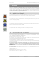
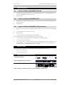
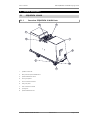
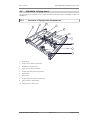
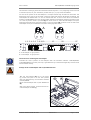
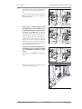
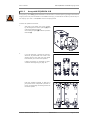
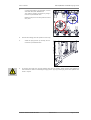
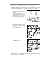
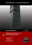
K&F�SEQUENZA�10�N/W/B�&�Flying�Frame
User's�Manual
Important�Information,
Please�Read�Before�Use!
KLING & FREITAG GmbH
Junkersstraße 14
D-30179 Hannover
TEL +49 (0) 511 96 99 70
FAX +49 (0) 511 67 37 94
www.kling-freitag.de
Revison 6.0
Released: 29.01.2010
User's manual
K&F SEQUENZA 10 N/W/B & Flying Frame
Table of contents
1
Introduction
6
1.1
Symbols in User's Manual
6
1.2
Information about this User's Manual
6
2
Scope�of�Delivery
7
2.1
Scope of Delivery SEQUENZA 10 N/W
7
2.2
Scope of Delivery SEQUENZA 10 B
7
2.3
Scope of Delivery SEQUENZA 10 Flying Frame
7
3
Required� Tools
7
4
System�Requirements�for�Use
7
5
Product�Description
8
5.1
5.1.1
5.2
5.2.1
5.3
5.3.1
6
SEQUENZA 10 N/W
8
Overview SEQUENZA 10 N/W Parts
8
SEQUENZA 10 B
9
Overview SEQUENZA 10 B Parts
9
SEQUENZA 10 flying frame
10
Overview of flying frame Components
10
Safety�Instructions
11
6.1
Safety Instructions for Flown Setup
11
6.2
Safety Instructions for Stacked Setups
12
6.3
Wind Loading
14
6.4
Protecting the Speakers / Operating Safety
15
7
Using�the�Quick�Release�Pins
16
8
Removing�the�Transport�Covers
16
9
Positioning�of�the�Load�Adapters
16
10
Flown� Setup
18
10.1
Combining the Speaker Array
18
10.1.1
Array with SEQUENZA 10 N/W
18
10.1.2
Array with SEQUENZA 10 B
22
10.1.3
Array with SEQUENZA 10 N/W and SEQUENZA 10 B
25
10.2
Lifting the Array
26
10.2.1
Arrays with SEQUENZA 10 B
26
10.2.2
Arrays with SEQUENZA 10 N/W and 5m maximal Length
26
10.2.3
Arrays with SEQUENZA 10 N/W exceeding a Length of 5m
28
11
11.1
Flown�Disassembly
30
Disassembly of arrays with SEQUENZA 10 N/W exceeding a Length of
5m
KLING & FREITAG GMBH © 2009
Revision 6.0
31
Page 3 of 65
User's manual
11.2
12
K&F SEQUENZA 10 N/W/B & Flying Frame
Disassembly of arrays with SEQUENZA 10 N/W and a maximum Length of
5m
31
Stacked� Setup
12.1
32
SEQUENZA 10 N/W stacked
32
12.1.1
Preparing the Flying Frame
32
12.1.2
Mounting the Speakers
33
12.2
SEQUENZA 10 B stacked
36
12.3
SEQUENZA 10 N/W stacked on SEQUENZA 10 B
37
13
Disassambling�the�Stacked�Array
38
14
Cardioid�Arrays�with�SEQUENZA�10�B
38
14.1
Setup instructions for a cardioid array
39
14.2
Controller setups for cardioid use
41
15
SEQUENZA�10�B�combined�with�other�K&F�tops.
41
16
Fuse�in�the�SEQUENZA�10�B
42
16.1
17
Replacing the Fuses
42
Wiring
42
17.1
Cabling a K&F System Rack
42
17.2
Connecting the SEQUENZA 10 N/W
43
17.3
Connecting the SEQUENZA 10 B
44
17.4
Fixating the Cables
45
18
Transport�and�Storage
45
19
Maintenance�and�Care
45
19.1
Inspection Intervals and Items
46
20
Optional�BGV�C1�Certification
46
21
Technical�Specifications�of�Loudspeakers
47
21.1
Technical Specifications SEQUENZA 10 N
47
21.2
Technical Specifications SEQUENZA 10 W
48
21.3
Technical Specifications SEQUENZA 10 B
49
22
Measuring�diagrams
50
22.1
SEQUENZA 10 N diagrams
50
22.2
SEQUENZA 10 W diagrams
52
22.3
SEQUENZA 10 B diagrams
54
23
Dimensions�speaker
56
23.1
Dimensions SEQUENZA 10 N/W
56
23.2
Dimensions SEQUENZA 10 B
57
24
Dimensions�and�weight�flying�frame
58
25
Accessories
59
25.1
General Accessories for SEQUENZA 10
KLING & FREITAG GMBH © 2009
Revision 6.0
59
Page 4 of 65
User's manual
K&F SEQUENZA 10 N/W/B & Flying Frame
25.2
Accessories for SEQUENZA 10 N/W
60
25.3
Accessories for SEQUENZA 10 B
61
25.4
Accessories for SEQUENZA 10 Flying Frame
62
26
Disposal
26.1
63
Regulations for Disposal
63
26.1.1
Germany
63
26.1.2
EU, Norway, Iceland, and Liechtenstein
63
26.1.3
All other Countries
63
27
Declaration�of�Conformity�(CE)
64
27.1
CE Rigging System
64
27.2
CE Loudspeaker
65
KLING & FREITAG GMBH © 2009
Revision 6.0
Page 5 of 65
User's manual
1.
K&F SEQUENZA 10 N/W/B & Flying Frame
Introduction
Thank you for your decision to buy a KLING & FREITAG sound system. To guarantee a trouble-free operating of the equipment and to allow your KLING & FREITAG Sequenza 10 system to achieve its full
potential please read the operating instructions carefully before use. With the purchase of a SEQUENZA
10 system, you have acquired a large sound system with the highest possible quality and performance
capabilities. As the owner of a SEQUENZA 10 system, you now have a versatile and highly professional
tool which, when operated properly, is a true pleasure to use.
1.1
Symbols�in�User's�Manual
This symbol indicates the possibility of life-threatening danger and a health risk for persons. Not following
these instructions may result in serious health problems including potentially fatal injuries.
Warning
This symbol indicates a possibly dangerous situation. Not following these instructions may cause minor
injuries or cause property damage.
Caution
This symbol gives instructions for the proper use of the described products. Not following these instructions may cause malfunctions or property damage.
Important
This symbol indicates notes that help you to handle the described products easier.
Tip
1.2
Information�about�this�User's�Manual
User's Manual SEQUENZA 10 N and SEQUENZA 10 W in Combination with the SEQUENZA 10 Flying
Frame. SEQUENZA 10 N/WSEQUENZA 10 BSEQUENZA 10
© Kling & Freitag GmbH, 2008, all rights reserved.
All specifications in this manual are based on information available at the time of publishing for the
features and safety guidelines of the described products.
Technical specifications, measurements, weights and properties are not guaranteed.
The manufacturer reserves the right to make product alterations within legal provisions as well as changes
to improve product quality.
All�persons�who�use�the�speaker�system�must�have�this�guide�and�all�further�information�for
safe�operations�available�to�them�during�assembly,�disassembly,�and�use.The�speaker�system
may�neither�be�set�up�nor�used�until�this�manual�has�been�read,�understood�and�kept�readily
available�on�site.
We appreciate any input with suggestions and improvements for this manual. Please send this to us at
the following address:
[email protected] or to:
KLING & FREITAG GMBH Junkersstr.14 D-30179 Hannover.
Phone +49 (0) 511 - 96 99 70, Fax +49 (0) 511 - 67 37 94
KLING & FREITAG GMBH © 2009
Revision 6.0
Page 6 of 65
User's manual
2.
2.1
K&F SEQUENZA 10 N/W/B & Flying Frame
Scope�of�Delivery
Scope�of�Delivery�SEQUENZA�10�N/W
•
Full-range loudspeaker with integraten 'Snap&Fly' Rigging System incl. Quick Release Pins (usable with SEQUENZA 10 Flying Frame only)
•
User's Manual
2.2
Scope�of�Delivery�SEQUENZA�10�B
•
Subwoofer with integraten Rigging System incl. Quick Release Pins (usable with SEQUENZA 10
Flying Frame only)
•
User's Manual
2.3
Scope�of�Delivery�SEQUENZA�10�Flying�Frame
•
Flying frame to hang and stack SEQUENZA 10 N/W speakers incl. Quick Release Pins SEQUENZA
10
•
2 x 3.25t shackles (for optional safety chain)
•
User's Manual
•
Calculation software CON:SEQUENZA CON:SEQUENZA
The following material is optionally available for flying the flying frame:
•
3 level-adjustable hinged heavy-duty feet (mandatory for stacking speakers)
•
2 x 3.25t shackle for load adapter
•
2-strand safety chain: 2 x 8mm steel chain / Grade 8 / Length 380mm per strand (Working load
limit (WLL) BGV C1: 1250 kg) with 2 x hooks DIN 5691 WLL BGV C1: 1250 kg) / Rigging link
shape A according to DIN 56882 (WLL BGV C1: 1750 kg)
3.
Required�Tools
For the optionally available hinged heavy-duty feet of the SEQUENZA 10 flying frame:
•
24 mm open-end wrench
•
17 mm open-end wrench
4.
System�Requirements�for�Use
Connector�Panel�CP�4
K&F�CD�44�Digital�System�Controller
LAB.GRUPPEN�FP�10000Q:
These�components�will�be�referred�to�as�'K&F�SystemRack'�in�this�manual.
KLING & FREITAG GMBH © 2009
Revision 6.0
Page 7 of 65
User's manual
5.
K&F SEQUENZA 10 N/W/B & Flying Frame
Product�Description
5.1
5.1.1
SEQUENZA�10�N/W
Overview�SEQUENZA�10�N/W�Parts
1.
speaker enclosure
2.
Park position Quick Release Pins
3.
Quick Release Pins front
4.
front joint plates
5.
front connector bracket
6.
rear joint plate
7.
rear connector bracket
8.
spring bolt
9.
Quick Release Pin rear
KLING & FREITAG GMBH © 2009
Revision 6.0
Page 8 of 65
User's manual
5.2
5.2.1
K&F SEQUENZA 10 N/W/B & Flying Frame
SEQUENZA�10�B
Overview�SEQUENZA�10�B�Parts
1
2
3
4
5
1.
speaker enclosure
2.
Stacking grooves / cover, adjacent: stacking feet / bottom
3.
Threaded stand flange
4.
Stacking feet / side, adjacent: stacking grooves / side
5.
joint plates
6.
connector brackets
7.
Quick Release Pins in park position
KLING & FREITAG GMBH © 2009
Revision 6.0
6
7
Page 9 of 65
User's manual
5.3
K&F SEQUENZA 10 N/W/B & Flying Frame
SEQUENZA�10�flying�frame
This flying frame was designed to fly or stack the KLING & FREITAG speakers SEQUENZA 10 N/W. SEQUENZA 10
5.3.1
Overview�of�flying�frame�Components
2
3
4
1
5
6
7
8
9
10
1.
hinge fitting
2.
fixing point for Rieker inclinometer
3.
SEQUENZA 10 flying frame
4.
fixing plate for SSE inclinometer
5.
Hinged heavy-duty feet rear (optional)
6.
load adapter
7.
stacking link
8.
Hinged heavy-duty feet front (optional)
9.
park position for load adapter
10. fixing points for safety chain
KLING & FREITAG GMBH © 2009
Revision 6.0
Page 10 of 65
User's manual
6.
K&F SEQUENZA 10 N/W/B & Flying Frame
Safety�Instructions
The information described here does not relieve the user of the duty to follow the given safety requirements and legal regulations.
Warning
The technicians responsible for assembling the flying frame on site are responsible for the safe setup and
use of the flying frame and guarantee this.
To prevent damage to persons and property, you must set up or suspend the array in compliance with
the specifications of the German safety regulation BGV C1 or comparable applicable national standards.
At least 2 people are necessary to set up the array.
The flying frame is solely for professional use and only for the suspension of the KLING & FREITAG
speaker models SEQUENZA 10 N, SEQUENZA 10 W, SEQUENZA 10 B in the manner described here.
If the simulation software CON:SEQUENZA displays "Load-Failed", the array may not be set up in the
configuration simulated in the software. CON:SEQUENZA
When laying out the connecting cables, make sure that nobody can trip.
If not otherwise stated in this manual, only original KLING & FREITAG parts may be used for mounting
the speakers. The use of other parts - in particular parts by other manufacturers - is not permitted.
For mobile and fixed installations, use only assembly equipment from KLING & FREITAG.
As a basic principle, you must visually inspect all components of the array before every use. For fixed
installations, you must inspect all components of the rigging system for signs of wear at regular intervals.
The visual inspection includes checking the components of the speakers, the flying frame, the loadbearing parts (cross beams, ceiling constructions, etc.) and their bolted connections. When inspecting
components of the flying frame, pay special attention to any deformations, cracks, damage to threads,
and corrosion as well as the functional capability of the Quick Release Pins and the functional capability
of the spring bolts. Mounting devices such as shackles, chains and wire ropes also have to be checked for
signs of wear or deformation carefully. If there are signs of wear, cracks, or deformation, etc. then you
must replace the parts immediately. For further instructions, refer to chapter "Maintenance and Care"
on page 45.
6.1
Safety�Instructions�for�Flown�Setup
Falling�speakers�pose�the�threat�of�fatal�injuries�to�people�near�them!
If�you�have�even�the�slightest�reason�to�doubt�the�safety�of�the�rigging�system,�then�you�may
not�use�it�under�any�circumstance.
Warning
Only�trained�event�technicians�may�suspend�the�flying�frame.
Never suspend the speakers without the appropriate flying frame.
The maximum working load limit (WLL) of the flying frame is – depending on the selected load bearing
drillings and types of speakers – 625�kg�-�1000�kg.
This specification includes cabling and additional fittings. The provided simulation software
'CON:SEQUENZA' must be used to determine if the frame is loaded permissibly. The simulation software
CON:SEQUENZA does not take the weight of cabling and additional fittings into consideration! When
following the specifications of the CON:SEQUENZA calculation software, consider this additional weight
and reduce the number of speakers accordingly.
If the simulation software does not confirm the compliance with DIN 18 800, the array may not be
assembled in the simulated setup.
KLING & FREITAG GMBH © 2009
Revision 6.0
Page 11 of 65
User's manual
K&F SEQUENZA 10 N/W/B & Flying Frame
If the simulation software CON:SEQUENZA does not confirm the compliance with BGV C1, no one may
be situated in this area between the assembly and disassembly – not even those involved in assembly
and disassembly. You must effectively block off this area and secure it from trespassing.
Warning
The following arrays (maximum configurations) fulfil the stipulations of the BGV C1 with their given
design:
Maximum�number�of�flown�speakers:
•
SEQUENZA�10�N�and�SEQUENZA�10�W:
Arrays of up to 13 speakers and a flying frame inclination less than +/- 4°.
•
SEQUENZA�10�B:
Arrays of up to 12 speakers.
•
SEQUENZA�10�N/W�combined�with�SEQUENZA�10�B:
For combined arrays consisting of SEQUENZA 10 N/W and SEQUENZA 10 B, a special verification
with the CON:SEQUENZA simulation software is mandatory.
If these angles or the number of speakers is exceeded, it is mandatory that you separately verify the array
with the CON:SEQUENZA simulation software. CON:SEQUENZA
Ensure that all connections are secured against coming loose and that only authorized, statically tested
and correctly sized supports, mounting equipment, wire ropes and chains are used.
Follow the relevant specified safety factors. The safety factors (SF) are stated on the back of the speakers
and they comply with the BGV C1. Be sure to follow the relevant national specifications, norms, and
safety regulations.
Note that every suspension point as well as the supporting structure of the building (i.e. ceiling points,
cross beams and stage or PA tower, etc.) must be capable of carrying the total load of the system (including cabling and additional fittings).
Note that the suspension points on the hall ceiling (i.e. shackles, suspension points, or chain points)
must comply with the accident prevention regulation BGV C1 (Event and Production Sites for Stage
Presentations) or comparable applicable national standards, and the total load must be approved by an
authorised expert. If in doubt, have it checked by local authorities.
Also, follow the operating and safety instructions for the product from which you will suspend the flying
frame (i.e. truss). If there is no information regarding the safe use and the working load limit, you may
not fly the flying frame from it.
Every chain and every motor must be capable of carrying the total load of the array on its own, even
with two-strand rigging. Check to make sure that the chains of the hoist motors are hanging straight
down and are not twisted and that the hoist motors are in the intended positions.
When operating with chain hoists that do not comply with the BGV C1 or the D8+, no one may be
present in the danger zone underneath or near the speaker array.
Secure the array from falling with a second independent safety fitting if no BGV C1 or D8+ motor is used.
Never use signal cables or power cords for suspending, aligning or securing the systems. When laying
out the connecting cables, make sure that nobody can trip.
Make sure you have enough free working space on site to assemble and suspend the array.
The array can swing out while being lifted!
Only personnel directly involved with assembly or disassembly may be in the working area. Every time
before the responsible technician raises or lowers the flying frame, he must unmistakably signal this to
all people. All persons must then move outside of the pivoting and lifting range.
The flying frame may not be used to lift and secure people or objects other than the above-mentioned
speaker systems.
The array may not be used as a climbing aid.
The safe use of the flying frame and the speakers also depends on the various factors present at the
area of use. Weather conditions such as wind or rain, for example, can compromise the safety of the
flying frame and speakers. Always consider and evaluate these factors. (See chapter "Wind Loading"
on page 14.)
KLING & FREITAG GMBH © 2009
Revision 6.0
Page 12 of 65
User's manual
6.2
K&F SEQUENZA 10 N/W/B & Flying Frame
Safety�Instructions�for�Stacked�Setups
Falling�speakers�pose�the�threat�of�fatal�injuries�to�people�near�them!
Be sure to follow the relevant national specifications, norms, and safety regulations.
Warning
Always make sure that a sufficient safety level is still given, even when outside forces have an additional
impact on the stacked speakers. Before setup, carefully ascertain if there are any possible outside forces
that could result in the array falling over. (Slant of the ground / the bearing capacity of the ground /
wind / person or vehicle impact, etc.). A technical expert who is responsible for the setup must evaluate
and determine necessary measures (including calculating the statics). If necessary, obtain expert proof
of stability.
For the standard safety inspection, you must always factor in an imperfection (tilt) of +/-5° and destabilising loads. A planned tilt of the flying frame ist not permissible. In calculations, the tilted setup serves
the purpose of levelling out unevenness.
With the set-up systems for which you cannot verify the structural safety without safeguards, you must
secure them to prevent sliding or tipping in order to provide proof of this safety. To secure the system from
tipping over, use water tanks or floor bolts. Other possible measures include strapping it to a suitable
substructure or tying it using safety straps. The simulation in the CON:SEQUENZA software is not valid
as a verification of structural safety. This software always states that you must secure stacked speakers
to prevent their falling over.
For outdoor and trade fair venues in which wind loads must be considered, additional proof of stability
is necessary.
Only stack the SEQUENZA 10 N/W systems in conjunction with the SEQUENZA 10 flying frame and
the optionally available SEQUENZA 10 Ground Stack Kit (stacking feet), which is intended to be used.
Stacking of SEQUENZA 10 N/W without the optional feet is not permissible!
Make sure that the stacking feet of subwoofers stacked on top of one another are securely positioned
in the grooves of the lower speaker.
Maximum� number� of� stacked� speakers� (Valid for indoor operations without wind, with a person
impact of 10 kg at a height of 1.5 m and a flying frame tilt of 5°):
•
SEQUENZA�10�N�and�SEQUENZA�10�W:
arrays with up to 7 x SEQUENZA 10 N/W. To fixate the system to the floor, you can use the
openings in the optional stacking feet (SEQUENZA 10 Ground Stack Kit).
•
SEQUENZA�10�B�flat:
Arrays with up to 6 x SEQUENZA 10 B
•
SEQUENZA�10�B�vertical:
Arrays with up to 2 x SEQUENZA 10 BYou must additionally secure vertically standing stacked
SEQUENZA 10 B systems from falling since the structural safety is not guaranteed, otherwise.
Possible measures include strapping them to a suitable substructure or tying them using safety
straps.
•
SEQUENZA�10�N/W�combined�with�SEQUENZA�10�B
arrays with up to 7 x SEQUENZA 10 N/W on 6 x SEQUENZA 10 B.
SEQUENZA�10�B
If you are stacking a K&F top with feet (i.e. Line 212) on top of a SEQUENZA 10 B subwoofer that is placed
on its side, make sure that the Quick Release Pins have not been damaged in their stand-by positions.
You must always strap such setups to one another and secure them from falling over.
KLING & FREITAG GMBH © 2009
Revision 6.0
Page 13 of 65
User's manual
6.3
K&F SEQUENZA 10 N/W/B & Flying Frame
Wind�Loading
For open air events, obtain current local wind and weather data. The following chart provides a preliminary indication
Bft
m/s
Windspeed
Description
0
0-0.2
Calm
Smoke rises vertically
1
0.3-1.5
Light air
Smoke drift indicates
wind direction, vanes do
not move
2
1.6-3.3
Light
Wind felt on face, vanes
begin to move
3
3.4-5.4
Gentle
Leaves, small twigs in
constant motion, light
flags extended
4
5.5-7.9
Moderate
Dust, leaves, and loose
paper raised up, small
branches move
5
8.0-10.7
Fresh
Small trees in leaf begin to sway, whitecaps
on lakes visible
6
10.8-13.8
Strong
Larger branches of trees
in motion; whistling
heard in wires
7
13.9-17.1
Near gale
Whole trees in motion;
resistance felt in walking
against wind
8
17.2-20.7
Gale
Twigs and small branches
broken off trees
For outdoor uses, we recommend using at least a BGV D8+ hoisting device to avoid wind causing the
release of the secondary safety device.
Warning
If wind speeds higher than Beaufort 5 are expected, you must constantly consider the wind speed and its
possible influence on the array as well as the fact that the wind speed increases the higher the array is.
With expected wind speeds exceeding Beaufort 5, construct the rigging and safety points so that they
can carry at least twice the static load.
With wind speeds exceeding Beaufort 6 (14 m/sec.), arrays are not recommended.
As of a wind speed of Beaufort 6, you must clear the area under the speakers. Effectively prevent the
arrays from swaying in the wind by tying them off or using a lateral fixation. If the suspended load sways,
it can create significant inertial force that can result in the PA tower structurally collapsing or tipping.
With wind speeds of Beaufort 8 or more, you must lower and disassemble the array.
KLING & FREITAG GMBH © 2009
Revision 6.0
Page 14 of 65
User's manual
6.4
K&F SEQUENZA 10 N/W/B & Flying Frame
Protecting�the�Speakers�/�Operating�Safety
SEQUENZA 10 speakers may only be used in combination with a K&F SystemRack. See chapter [System
Requirements for Use] on page 7.
Caution
In general, audio signals should not be overdriven. This may be caused by mixing consoles, equalizers,
effect equipment, etc. and should be indicated on this equipment. When a power amplifier is overloaded
at the output (clipping), then the amplifier activates a clipping warning signal. In any case, the signal
must be reduced as soon as it sounds unnaturally distorted.
For�damage�caused�by
•
overloading the speakers
•
The rear-facing subwoofer is controlled using the Controller CD 44 via LSBlock for cardioid / hypercardioid arrays for rear-emitting subwoofers. The front-facing subwoofers are controlled via
LSBlock for cardioid / hypercardioid arrays for front-emitting subwoofers.
we do not assume warranty and excludes liability for possible consequential damage.
The�following�signals�may�damage�the�speakers:
•
permanent high-level signals with high frequency and continuous noise from feedback.
•
permanently distorted high-level signals.
•
noises, which occur when the amplifier is on while equipment is being con-nected, disconnected
or switched on.
Do�not�install�devices�in�any�of�the�following�places:
•
where the devices are permanently exposed to direct sunlight.
•
where the devices are exposed to high moisture or rain.
•
where the devices are exposed to strong vibrations and dust.
Damage�caused�by�the�speakers'�magnetic�fields
Speakers are permanently surrounded by a magnetic field, even when they are not connected. Therefore,
during transport and placement of the speakers, it is important to ensure that there is always approx. 1
m between the speakers and magnetic data media and computer/video monitors.
Preventing�hearing�damage
Avoid beeing too close to operating speakers. Even loudness levels of approx. 90 dB - that you subjectively
judge as being low - can lead to hearing damage.
KLING & FREITAG GMBH © 2009
Revision 6.0
Page 15 of 65
User's manual
7.
K&F SEQUENZA 10 N/W/B & Flying Frame
Using�the�Quick�Release�Pins
The Quick Release Pins are equipped with retaining balls. By pushing the button in the middle of the pin,
you can release these balls and then insert or remove the pin. As long as you do not push the button in
the middle of the pin, you should not be able to pull out the pin.
8.
Removing�the�Transport�Covers
In order to remove the transport cover, push the
latch in the round opening towards the middle of
the transport cover (1), slightly pull the transport
cover on the side of the latch toward you (2), and
remove the cover to the side (3).
When doing this, do not pull the transport cover towards you too much, as this could cause the catch
on the other side of the cover to bend.
2
3
1
9.
Positioning�of�the�Load�Adapters
You can calculate one- and two-strand riggings with the simulation software CON:SEQUENZA. For onestrand rigging, use one load adapter; for two-strand rigging, use two load adapters.
The drill holes on the flying frame where the load adapters are to be attached are determined by the
simulation software CON:SEQUENZA. CON:SEQUENZAYou will find the specifications on the relevant
calculation printouts. The specification of the drill hole in the simulation software refers to the drill hole
in the load adapter that is facing the front side of the frame. The front side of the frame is marked with
a sticker (Front).
KLING & FREITAG GMBH © 2009
Revision 6.0
Page 16 of 65
User's manual
K&F SEQUENZA 10 N/W/B & Flying Frame
The drill holes in the flying frame are numbered consecutively from 1 to 27, beginning on the front end
of the frame (Front). For your orientation, the drill holes 5, 9, 15, 20, and 26 are labelled.
You can set the position of the load adapters in 1/2-steps because they are usable on both sides. This
doubles the grid of the row of drill holes in the flying frame and thus the adjustment possibilities. The
load adapters are labelled with '1/1 Grid' on the one side and '1/2 Grid' on the other. The simulation
software CON:SEQUENZA gives you the information whether a load adapter should be mounted in the
1/1 or the 1/2 position. In the 1/1 position (A), the arrow on the 1/1 side of the load adapter must point
toward the front side of the flying frame (Front). In the 1/2 position (B), the arrow on the 1/2 side of the
load adapter must point toward the front side of the flying frame (Front).
A
B
1, 2, 3, 4, 5, 6, 7, 8, 9,10...............15................20........................27
5
TO BE USED BY QUALIFIED
RIGGERS ONLY !
9
15
B
SAVE WORKING LOAD:
STACKING
A
READ MANUAL AND SAFETY
INSTRUCTIONS BEFORE USE !
(BGV C1 / SF 5 / SECONDARY SAFETY)
FLYING 0°
SUSPEND K&F SEQUENZA 10
MINIMUM 625 kg
@ALL HOLE POSITIONS
Manufacturing Year:
Weight:
Ser.-No.:
FLYING +3°
41kg
MAXIMUM 1000 KG
FROM HOLE POSITION 1 TO 21
SECURE FRAME WITH A
SECONDARY 2 LEG SAFETY !
20
STACKING TABLE
INCLINATION
A
B
CABINET
7°
6°
5°
4°
3°
2°
1°
0°
2.9°
2.0°
0.9°
0.0°
-1.1°
-2.0°
-3.1°
-4.0°
-2.4°
-3.2°
-4.4°
-5.2°
-6.4°
-7.3°
-8.5°
-9.2°
26
REAR FOOT
PINS ONLY !
MODEL:
SEQUENZA 10
FLYING FRAME 24
CABLE PICK
AND
ADJUSTMENT
POINT
A = Load adapter 1/1 grid position
B = Load adapter 1/2 grid position
Instructions�for�mounting�the�load�adapter
Important
Calculate the correct position of load adapters with the simulation software CON:SEQUENZA.
CON:SEQUENZAIn this position, the array is guaranteed to fly at the desired angle later, and the sound
will be emitted correctly.
Always�mount�a�load�adapter�with�2�Quick�Release�Pins!
Warning
Take the load adapter (A) out of the standby position and place it on the hole position
that was determined by the simulation software
CON:SEQUENZA.
Mount the load adapter with 2 Quick Release Pins
(A).
With a two-strand rigging, proceed with the second load adapter accordingly.
KLING & FREITAG GMBH © 2009
Revision 6.0
Page 17 of 65
User's manual
K&F SEQUENZA 10 N/W/B & Flying Frame
10. Flown�Setup
10.1
Combining�the�Speaker�Array
10.1.1
Array�with�SEQUENZA�10�N/W
The splay angles of the individual speakers are determined by the simulation software CON:SEQUENZA.
CON:SEQUENZAYou will find the specifications on the relevant calculation printouts. On the rear joint
plate of the speakers, there are drill holes with the corresponding angles marked.
During setup, check every Quick Release Pin to ensure that it is locked in place by pulling it outwards!
Warning
1.
Slide the front joint plates out of the speaker
by reaching into the access opening (A) and
pushing the joint plate forwards.
Secure the joint plates(B) with the Quick Release Pins(C).
2.
Slide the speakers together so that the joint
plates protrude into the front connecting
bracket.
KLING & FREITAG GMBH © 2009
Revision 6.0
Page 18 of 65
User's manual
3.
K&F SEQUENZA 10 N/W/B & Flying Frame
Secure the connection with the Quick Release Pins.
Make sure all pins fit correctly and are locked
into place.
4.
Proceed accordingly with all speakers in the
array.
5.
Pull the rear Quick Release Pins of all speakers out of the stand-by position.
6.
Pull out the spring bolts of all speakers
and turn them by 90° to a vertical position
(open).
KLING & FREITAG GMBH © 2009
Revision 6.0
Page 19 of 65
User's manual
7.
K&F SEQUENZA 10 N/W/B & Flying Frame
Align the drill hole in the joint plate with the
drill hole that is marked with the desired angle.
Connect them using the Quick Release Pin
(A) and make sure the pin fits correctly and
is locked into place.
8.
Arrays� with� a� maximal� length� of� 5m
(corresponding�to�an�array�with�max.�16
x�SEQUENZA�10�N/W�incl.�flying�frame):
Turn all spring bolts (B) by 90° to a horizontal position (closed), so that they snap into
the guide slot of the spring bolt enclosure.
The spring bolts have not yet snapped into the drill hole of the rear joint plate. The
spring bolts, however, are all set so that they
automatically snap into place when you fly
the array, then creating a positive connection
with the selected angle position.
Arrays�with�a�length�exceeding�5m�(corresponding�to�an�array�with�more�than
16� x� SEQUENZA� 10� N/W� incl.� flying
frame):
Leave the spring bolts (B) in the vertical position.
9.
Stand the flying frame up vertically and remove the Quick Release Pins
KLING & FREITAG GMBH © 2009
Revision 6.0
Page 20 of 65
User's manual
K&F SEQUENZA 10 N/W/B & Flying Frame
10. Tipping of the flying frame with speakers can result in injuries. To prevent the frame from tipping
forward with the first speaker, always connect the speakers to one another first before connecting
the flying frame.
To prevent the frame from tipping forward with the first speaker, let the spring bolts of the first two
speakers snap into place before connecting the flying frame.
Caution
To do so, you must position the spring bolt of the second speaker horizontally and you may need
to tilt the speaker slightly until the spring bolt snaps into place.
11.
Place the frame in front of the top speaker
so that all joint plates (1) protrude into the
frame, then connect them using the Quick
Release Pins (2).
12.
Insert the rear joint plate (1) of the top
speaker between the drill holes for the desired angle, and secure it with the Quick Release Pin (2).
The tilt angle of the speakers relative to the
flying frame is determined by the simulation
software CON:SEQUENZA.
To fly the top speaker parallel (0°) to the flying frame, use the drill hole 'Flying 0°' (see
illustration).
To tilt the top speaker upwards by +3°, use
the 'Flying +3°' hole (see illustration).
13. Wire the speakers. Further information in chapter "Wiring" on page 42.
Please find more detailed information for wiring the SEQUENZA 10 speaker and configuring the CD
44 in the hardware user's manual for the CD 44.
14. Proceed as described in chapter [Lifting the Array] as of page 26.
KLING & FREITAG GMBH © 2009
Revision 6.0
Page 21 of 65
User's manual
10.1.2
K&F SEQUENZA 10 N/W/B & Flying Frame
Array�with�SEQUENZA�10�B
During setup, check every Quick Release Pin to ensure that it is locked in place by pulling it outwards! As
long as you do not push the button in the middle of the pin, you should not be able to pull out the pin.
You may fly up to max. 12 SEQUENZA 10 B on the flying frame.
Warning
Connect the speakers as follows:
1.
Slide the 4 joint plates out of the speaker
by reaching into the access opening (A) and
pushing the plates forwards.
Secure the joint plates(B) with the Quick Release Pins(C).
2.
If you are planning a cardioid or hypercardioid use, lay the middle one of the 3 subwoofers with its rear side onto the wheel
board before you connect the speakers
Further instructions for cardioide or hypercardioide uses beginning on page 38.
Push the speakers together so that the 4
joint plates of the one speaker protrude into the corresponding connecting bracket of
the other speaker.
KLING & FREITAG GMBH © 2009
Revision 6.0
Page 22 of 65
User's manual
3.
K&F SEQUENZA 10 N/W/B & Flying Frame
Connect the speakers, as illustrated, on both
sides with the Quick Release Pins.
You create a speaker connection by using a
total of 8 Quick Release Pins.
Make sure all pins fit correctly and are locked
into place.
4.
5.
6.
Proceed accordingly with all speakers in the array.
Stand the flying frame up vertically and remove the Quick Release Pins
To prevent the frame from tipping forward with the first speaker, always connect the speakers to
one another first before connecting the flying frame. Tipping of the flying frame with speakers can
result in injuries.
Caution
KLING & FREITAG GMBH © 2009
Revision 6.0
Page 23 of 65
User's manual
7.
8.
K&F SEQUENZA 10 N/W/B & Flying Frame
Place the frame in front of the top speaker
so that the joint plates (1) protrude into the
flying frame, then connect them using the
Quick Release Pins (2).
Wire the speakers. Further information in chapter "Wiring" on page 42.
Please find more detailed information for wiring the SEQUENZA 10 speaker and configuring the CD
44 in the hardware user's manual for the CD 44. SEQUENZA 10
9.
Proceed as described in chapter [Lifting the Array] as of page 26.
KLING & FREITAG GMBH © 2009
Revision 6.0
Page 24 of 65
User's manual
10.1.3
K&F SEQUENZA 10 N/W/B & Flying Frame
Array�with�SEQUENZA�10�N/W�and�SEQUENZA�10�B
1.
Create an array with SEQUENZA 10 N/W, see chapter [Array with SEQUENZA 10 N/W] as of page 18.
2.
Create an array with SEQUENZA 10 B, see chapter [Array with SEQUENZA 10 B] as of page 22.
3.
Remove the 4 Quick Release Pins (A) on the
flying frame of the SEQUENZA 10 N/W array
and turn out the 4 angled joint plates (B), as
illustrated.
Secure the angled joint plate (B) with the
Quick Release Pin (A) in this position.
Proceed accordingly with the 3 remaining
angled joint plates of the flying frame.
4.
Push the SEQUENZA 10 N/W array and the
SEQUENZA 10 B array together so that all 4
angled joint plates of the flying frame protrude into the connecting brackets of the
lower SEQUENZA 10 B system.
5.
Secure all 4 angled joint plates with the remaining Quick Release Pins on the bottom
SEQUENZA 10 B system.
6.
Wire the speakers. Further information in chapter "Wiring" on page 42. Please find more detailed information for wiring the SEQUENZA 10 speaker and configuring the CD 44 in the hardware
user's manual for the CD 44. SEQUENZA 10
KLING & FREITAG GMBH © 2009
Revision 6.0
Page 25 of 65
User's manual
7.
K&F SEQUENZA 10 N/W/B & Flying Frame
Proceed as described in chapter [Lifting the Array] as of page 26.
10.2
Lifting�the�Array
See�the�instructions�in�chapter�[Safety�Instructions]�from�page�11�and�in�the�corresponding
sub-section�[Safety�Instructions�for�Flown�Setup]�from�page�11.
Warning
10.2.1
Arrays�with�SEQUENZA�10�B
This�description�is�valid�for�a�maximum�of�12�SEQUENZA�10�B�systems�connected�to�one�another.�More�than�12�SEQUENZA�10�B�systems�connected�to�one�another�may�not�be�flown.
1.
Attach a certified 3.25 ton shackle for every speaker used.
Secure the shackles against self-loosening (i.e. split pin).
2.
Hook the load hook of the hoist chain (i.e. of the hoist motor) into the load adapter's shackle and
begin to lift the array carefully.
3.
When the first speakers are at working height, remove the front transport covers.
4.
Lift the array evenly and slowly into its operating position so that it cannot swing out during lifting,
then secure it. In doing this, make sure that chain hoists and lifting accessories do not get caught.
Make sure that the speaker cables do not get crimped or get caught.
10.2.2
Arrays�with�SEQUENZA�10�N/W�and�5m�maximal�Length
This�description�is�valid�for�arrays�that�only�consist�of�SEQUENZA�10�N/W�systems�as�well�as�for
mixed�arrays�of�SEQUENZA�10�N/W�and�SEQUENZA�10�B�whose�total�length�does�not�exceed
5m.�(An�array�with�16�x�SEQUENZA�10�N/W�corresponds�to�a�length�of�5m).
1.
Attach a certified 3.25 ton shackle for every speaker used.
Secure the shackles against self-loosening (i.e. split pin).
2.
3.
Verify that every spring bolt of the SEQUENZA 10 N/W are in a horizontal position
(closed), so that they can lock into place
when lifting the array.
Hook the load hook of the hoist chain (i.e. of the hoist motor) into the load adapter's shackle and
begin to lift the array carefully.
KLING & FREITAG GMBH © 2009
Revision 6.0
Page 26 of 65
User's manual
4.
5.
K&F SEQUENZA 10 N/W/B & Flying Frame
Verify that every spring bolt locks into place.
When the spring bolts snap into place, they
make a clearly audible noise and protrude
out of the drill hole on the opposite side.
Check that the spring bolts protrude at least 0.5 mm out of the drill holes at the entire circumference
(A).
During lifting, the spring bolts snap into place successively from the flying frame downwards.
If the spring bolts do not properly snap into place, do not hoist the array any further until you have
corrected the error.
Warning
6.
When the first speakers are at working height, remove the front transport covers.
7.
When the first SEQUENZA 10 N/W speakers are at working height, you can attach the protective
weather covers for this speaker model, if necessary.
For outside uses, these optional protective weather covers with hook-and-loop fastener serve as rain
protection for the rear flying mechanics and the cable connections.
8.
Lift the array evenly and slowly into its operating position so that it cannot swing out during lifting,
then secure it. In doing this, make sure that chain hoists and lifting accessories do not get caught.
Make sure that the speaker cables do not get crimped or get caught.
KLING & FREITAG GMBH © 2009
Revision 6.0
Page 27 of 65
User's manual
10.2.3
K&F SEQUENZA 10 N/W/B & Flying Frame
Arrays�with�SEQUENZA�10�N/W�exceeding�a�Length�of�5m
This�description�is�valid�for�arrays�that�only�consist�of�SEQUENZA�10�N/W�systems�as�well�as
for�mixed�arrays�of�SEQUENZA�10�N/W�and�SEQUENZA�10�B�whose�total�length�exceeds�5m.
(An�array�with�16�x�SEQUENZA�10�N/W�corresponds�to�a�length�of�5m).
1.
Attach a certified 3.25 ton shackle for every speaker used.
Secure the shackles against self-loosening (i.e. split pin).
2.
When connecting the SEQUENZA 10 N/W
systems, leave the spring bolts in a vertical
position so that they cannot snap into place
during lifting.
Risk�of�crushing�hands!
The speakers move towards each other during lifting.
3.
4.
Hook the load hook of the hoist chain (i.e. of the hoist motor) into the load adapter's shackle and
begin to lift the array carefully.
Lift the array up far enough so that the
first speaker enclusures begin to touch each
other.SEQUENZA 10 N/W
KLING & FREITAG GMBH © 2009
Revision 6.0
Page 28 of 65
User's manual
5.
K&F SEQUENZA 10 N/W/B & Flying Frame
Position each spring bolt horizontally when
the corresponding speakers touch each other during lifting.
The spring bolts do not snap into place until the speaker enclosures begin to move apart again
and the preselected angle position is reached. It is possible that this will happen when the array
is relatively high.
6.
Check that the spring bolts protrude at
least 0.5 mm out of the drill holes at the
entire circumference (A).
Warning
7.
When the first speakers are at working height, remove the front transport covers.
8.
When the first SEQUENZA 10 N/W speakers are at working height, you can attach the protective
weather covers for this speaker model, if necessary.
For outside uses, these optional protective weather covers with hook-and-loop fastener serve as rain
protection for the rear flying mechanics and the cable connections.
9.
Lift the array evenly and slowly into its operating position so that it cannot swing out during lifting,
then secure it. In doing this, make sure that chain hoists and lifting accessories do not get caught.
Make sure that the speaker cables do not get crimped or get caught.
KLING & FREITAG GMBH © 2009
Revision 6.0
Page 29 of 65
User's manual
K&F SEQUENZA 10 N/W/B & Flying Frame
11. Flown�Disassembly
1.
Basically, you disassemble the array in the reverse order of assembly.
2.
Replace each transport cover when the speakers are hanging at working level.
3.
Just before the bottom speaker touches the
ground, pull the array in the direction of the
arrow.
This way, you make sure that the array does
not stand on the side of the bottom speaker,
but rather on the castors.
Always make sure that the chain hoist is
hanging vertically during lowering. If you do
not do this, the array could sway suddenly.
If the system is not standing on the castors,
this could lead to diagonal pull during further lowering.
Warning
4.
Lower SEQUENZA�10�B�arrays far enough that all systems are on the wheels, then prepare the
SEQUENZA 10 speakers for transport.
•
Place the used Quick Release Pins back onto their intended stand-by positions on the speaker
and flying frame.
•
Push all joint plates back into the speaker.
•
Dismantle all other used components so that they are not exposed and get damaged during
transport.
For arrays�with�SEQUENZA�10�N/W�and�a�length�exceeding�5m, proceed as described in subsection [Disassembly of arrays with SEQUENZA 10 N/W exceeding a Length of 5m].
For arrays�with�SEQUENZA�10�N/W�and�a�maximum�length�of�5m, proceed as described in
sub-section [Disassembly of arrays with SEQUENZA 10 N/W and a maximum Length of 5m].
KLING & FREITAG GMBH © 2009
Revision 6.0
Page 30 of 65
User's manual
11.1
1.
K&F SEQUENZA 10 N/W/B & Flying Frame
Disassembly�of�arrays�with�SEQUENZA�10�N/W�exceeding�a
Length�of�5m
Replace each transport cover when the speakers are hanging at working level.
2.
Just before the bottom speaker touches the
ground, two people must grab hold of the
speaker at the recessed handles.
Release the rear Quick Release Pins (1) first
and catch the speaker while it is swinging
down by holding it at the recessed handles.
Then release the lower front Quick Release
Pins of the next highest speaker (2) and remove the lowest speaker.
3.
2
2
Disassemble as many speakers in this manner until the array only has a remaining length of max. 5m
(For arrays only having SEQUENZA 10 N/W systems, this corresponds to 16 speakers). Then proceed
as described in sub-section [Disassembly of arrays with SEQUENZA 10 N/W and a maximum Length
of 5m].
11.2
1.
1
Disassembly�of�arrays�with�SEQUENZA�10�N/W�and�a�maximum�Length�of�5m
When all four castors of the SEQUENZA 10 N/W speaker touch the ground, pull the spring bolt
until it comes free.
During lowering, starting with the lowest speaker, there is a point for each speaker at which its rear
connection is force-free. Pull the spring bolts out at this moment.
2.
Prepare the SEQUENZA 10 system for transport:
•
After you have completely lowered the array, release all Quick Release Pins and push the
speakers apart.
•
With the SEQUENZA 10 N/W systems, set the Quick Release Pins of the rear connecting
brackets to the 0° position.
•
Push all rear joint plates of the SEQUENZA 10 N/W systems into their park position so that the
spring bolts snap back into place. To put it into the park position, use the drill hole that is not
completely drilled through in the rear joint plate.
•
Pull the front Quick Release Pins and put them into the park position of the speaker enclosure. If the safety cords on the Quick Release Pins protrude out of the side of the speaker,
turn the Quick Release Pins so that the safety cords are in the grooves. This way you can protect the safety cords from transport damage.
•
Push the front joint plates into the speaker.
•
Dismantle all other used components so that they are not exposed and get damaged during
transport.
KLING & FREITAG GMBH © 2009
Revision 6.0
Page 31 of 65
User's manual
K&F SEQUENZA 10 N/W/B & Flying Frame
12. Stacked�Setup
12.1
SEQUENZA�10�N/W�stacked
12.1.1
Preparing�the�Flying�Frame
The feet are available as optional accessories and serve to guarantee the stability, balance out unevenness,
and align the frame. Keep in mind that under certain circumstances, the feet can leave marks on the
ground.
It�is�not�permissible�to�stack�the�speakers�on�the�flying�frame�without�the�optionally�available
hinged�heavy-duty�feet!
Warning
During setup, check every Quick Release Pin to ensure that it is locked in place by pulling it outwards! As
long as you do not push the button in the middle of the pin, you should not be able to pull out the pin.
1.
2.
3.
Take the rear foot out of the park position
and insert it into the back of the frame.
Remove the top Quick Release Pins on the front end of the flying frame and turn the hinged fitting
between the metal plates so that one leg of the hinged fitting is pointing upwards.
Secure the hinged fitting (A) in this position
with the Quick Release Pin (B).
A
B
4.
Take one front foot out of the park position and insert it into the front of the frame.
5.
Proceed accordingly with the other side.
KLING & FREITAG GMBH © 2009
Revision 6.0
Page 32 of 65
User's manual
6.
K&F SEQUENZA 10 N/W/B & Flying Frame
Align the frame.
Loosen the lock nut (A) on top with a 24 mm
open-end wrench. Turn the threaded rod (B)
with a 17 mm open-end wrench to adjust
the height. Re-tighten the lock nut. The upper end of the thread is blank so that the
counternut cannot be completely removed.
Do not try to clear the thread again.
A
B
12.1.2
Mounting�the�Speakers
See�the�instructions�in�chapter�[Safety�Instructions]�from�page�11�and�in�the�corresponding
sub-section�[Safety�Instructions�for�Stacked�Setups]�from�page�12.
Warning
It is not permissible to stack the speakers on the flying frame without the optionally available hinged
heavy-duty feet!
During setup, check every Quick Release Pin to ensure that it is locked in place by pulling it outwards! As
long as you do not push the button in the middle of the pin, you should not be able to pull out the pin.
Caution
1.
You will get the specifications for the setting angle of the bottom speaker on the frame from the
simulation software CON:SEQUENZA. CON:SEQUENZA(The angle specifications refer to the centre
axis of each speaker.)
To determine the correct drill holes on the speaker and frame for the desired angle, look for the
desired angle in one of the two right colums (see illustration below).
2.
At the top of the appropriate column, the drill hole (A or B) in the flying frame is indicated where
you must insert the Stacking Link.
3.
In the column "Cabinet", the drill hole in the rear joining plate of the speaker is indicated where
you must insert the Stacking Link on the speaker.
KLING & FREITAG GMBH © 2009
Revision 6.0
Page 33 of 65
User's manual
4.
K&F SEQUENZA 10 N/W/B & Flying Frame
Take the stacking link out of the park position and set it to the desired position.
5.
Take the rear Quick Release Pins on the first speaker out of the park position.
6.
Pull the spring bolt out and hold it. Pull out the joint plate approx. 10 cm towards the spring bolt
and then let go of the spring bolt. By doing this, the rear joint plate is no longer in the way when
the speaker is stacked and then connected with the stacking link.
7.
8.
Place the speaker on the frame.
Make sure that the hinged fittings protrude
between the joining plates on the speaker.
Secure the front connections with the Quick Release Pins from the speaker.
Risk� of� crushing� hands!� When� lowering� the� speakers,� there� is� the� risk� of
crushing�your�hands�while�the�enclosure
parts� move� towards� each� other.� Make
sure�that�you�do�not�lower�the�speaker
with�jolting�movements.
KLING & FREITAG GMBH © 2009
Revision 6.0
Page 34 of 65
User's manual
9.
K&F SEQUENZA 10 N/W/B & Flying Frame
Lift up the back of the speaker, align the
Stacking Link (A) with the drill hole for the
desired angle and secure the connection
with the Quick Release Pin (B).
B
A
10. Push the front joint plates out of the first speaker and secure them with the Quick Release Pins.
11. Prepare the next speaker as described in steps 2 - 3.
12. Place the next speaker on the stack and secure the front connections with two Quick Release Pins.
13. Place the joint plate between the drill holes for the desired angle and connect them with the Quick
Release Pin.
14. Proceed accordingly with the remaining speakers.
15. Wire the array. Follow the instructions in chapter "Wiring" beginning on page 42.
KLING & FREITAG GMBH © 2009
Revision 6.0
Page 35 of 65
User's manual
12.2
1.
2.
K&F SEQUENZA 10 N/W/B & Flying Frame
SEQUENZA�10�B�stacked
Securely place the bottom subwoofer onto a level surface.
Stack the subwoofers on top of one another.
Make sure that the stacking feet of subwoofers stacked on top of one another are
securely positioned in the grooves of the
lower speaker.
You can connect horizontally stacked systems with the joint plates.
You must additionally secure vertically standing stacked SEQUENZA 10 B systems from
falling since the structural safety is not guaranteed, otherwise.
KLING & FREITAG GMBH © 2009
Revision 6.0
Page 36 of 65
User's manual
12.3
1.
2.
K&F SEQUENZA 10 N/W/B & Flying Frame
SEQUENZA�10�N/W�stacked�on�SEQUENZA�10�B
Stack the subwoofers on top of one another.
Slide the joint plate out of the speaker by
reaching into the access opening (A) and
pushing the joint plate up.
Secure the joint plates with the two Quick
Release Pins (B) and (C).
3.
Proceed accordingly with the three remaining plates that connect the subwoofers.
4.
As needed, repeat the process for the next subwoofers that are stacked on one another.
5.
Lay the flying frame on top of the uppermost
subwoofer, as illustrated.
Slide the joint plate out of the speaker by
reaching into the access opening (A) and
pushing the joint plate up.
Secure the joint plates with the two Quick
Release Pins (B) and (C).
6.
Proceed accordingly with the three remaining plates of the subwoofer.
7.
The remainder of the setup is the same as the stacked SEQUENZA 10 N/W -> Mounting the Speakers,
see page 33.
KLING & FREITAG GMBH © 2009
Revision 6.0
Page 37 of 65
User's manual
K&F SEQUENZA 10 N/W/B & Flying Frame
13. Disassambling�the�Stacked�Array
1.
Basically, you disassemble the array in the reverse order of assembly.
2.
Replace the transport cover.
3.
Prepare the system for transport:
•
Place the used Quick Release Pins back onto their intended stand-by positions on the speaker
and flying frame.
•
Push all joint plates back into the speaker.
•
Dismantle all other used components so that they are not exposed and get damaged during
transport.
•
With the SEQUENZA 10 N/W systems, set the Quick Release Pins of the rear connecting
brackets to the 0° position.
•
Push all rear joint plates of the SEQUENZA 10 N/W systems into their park position so that the
spring bolts snap back into place. To put it into the park position, use the drill hole that is not
completely drilled through in the rear joint plate.
14. Cardioid�Arrays�with�SEQUENZA�10�B
The subwoofer SEQUENZA 10 B is designed so that it can be used as a cardioid and hypercardioid system
in an array of three subwoofers, or in multiples of three.
A cardioid array results in an increase of sound pressure towards the front because of the rear-facing
subwoofer. In the rear area (cardioid) or in the lateral side area (hypercardioid), on the other hand,
the sound pressure is clearly reduced.
With this, you achieve
•
less unwanted sound on the stage
•
low feedback
•
simplified miking
•
improved room acoustics with fewer reflections from the rear and side walls, or – when flown –
from the ceiling
•
simplified adherence of sound emission limits and therefore less noise disturbance for nearby
residential areas during open air events.
KLING & FREITAG GMBH © 2009
Revision 6.0
Page 38 of 65
User's manual
14.1
K&F SEQUENZA 10 N/W/B & Flying Frame
Setup�instructions�for�a�cardioid�array
To achieve a cardioid or hypercardioid pattern, you must always have an array with 3 subwoofers - or a
multiple of 3 subwoofers - setup next to one another (3, 6, 9, etc.). In this set of three, the middle one
must be stacked or flown rear-facing while both other subwoofers are front-facing.
The subwoofer and the flying frame SEQUENZA 10 allow for these setup options with their given design.
You can stack the subwoofers even when they are facing opposite directions, and you can connect them
to front-facing systems.
There is an additional Speakon connector on the front grille so that you can connect the cables to the
rear-facing side of all subwoofers in a cardioid array.
You can choose from the following options for cardioid and hypercardioid setups:
3 x SEQUENZA 10 B horizontal
3 x SEQUENZA 10 B vertical
3 x SEQUENZA 10 B stacked
KLING & FREITAG GMBH © 2009
Revision 6.0
Page 39 of 65
User's manual
K&F SEQUENZA 10 N/W/B & Flying Frame
When cardioid arrays are stacked on the floor, ensure that there is always a distance of at least 40 cm
between each unit of 3.
40 cm [1,3 ft]
40 cm [1,3 ft]
40 cm [1,3 ft]
KLING & FREITAG GMBH © 2009
Revision 6.0
Page 40 of 65
User's manual
14.2
K&F SEQUENZA 10 N/W/B & Flying Frame
Controller�setups�for�cardioid�use
The rear-facing subwoofer is controlled using the Controller CD 44 via LSBlock for cardioid / hypercardioid
arrays for rear-emitting subwoofers. The front-facing subwoofers are controlled via LSBlock for cardioid /
hypercardioid arrays for front-emitting subwoofers. The following cardioid or hypercardioid setups are
available in the CD 44:
Operation�Mode�of�the�SEQUENZA�10�B
Controller�Setup
'Cardioid Front', front-facing
SEQ10B C-F
'Cardioid Rear', rear-facing
SEQ10B C-R
'Hypercardioid-Front', front-facing
SEQ10B HC-F
'Hypercardioid-Rear', rear-facing
SEQ10B HC-R
'Infrabass Cardioid Front', front-facing
SEQ10B C-F60Hz
'Infrabass Cardioid Rear', rear-facing
SEQ10B C-R60Hz
'Infrabass Hypercardioid Front', front-facing
SEQ10B HC-F60Hz
'Infrabass Hypercardioid Rear', rear-facing
SEQ10B HC-R60Hz
15. SEQUENZA�10�B�combined�with�other�K&F�tops.
The SEQUENZA 10 B can also be combined with other K&F tops – in addition to the SEQUENZA 10 N/
W systems – using the Controller CD 44.
•
To do so, select the desired LS blocks for the top in the Controller CD 44, and combine these
with the desired LS block for the SEQUENZA 10 B.
•
Then activate the 'Combi Mode' by switching on Filter B for the SEQUENZA 10 B channel.
When�combining�with�SEQUENZA�10�N/W�tops,�Filter�B�(Combi�Mode)�may�not�be�switched�on!
In the CD 44 Hardware Manual, you will find a detailed description about connecting the SEQUENZA 10
speakers and the settings necessary on the System Controller CD 44. SEQUENZA 10 B
On the top side of the subwoofer, there is a threaded flange (M20) for screwing in an optionally available
distance rod.
All K&F tops with a flange connector or an assembled stand adapter can be placed onto this distance rod.
When you assemble a top onto a subwoofer using a distance rod, the structural safety is reduced. In this
case, you must take suitable measures in order to guarantee the structural safety.
Warning
For subsequent repositioning, always remove the top speaker that has been positioned using a distance
rod.
KLING & FREITAG GMBH © 2009
Revision 6.0
Page 41 of 65
User's manual
K&F SEQUENZA 10 N/W/B & Flying Frame
16. Fuse�in�the�SEQUENZA�10�B
To increase the operating safety of the SEQUENZA 10 B, the subwoofers are equipped with fuses at
the signal input. These fuses reduce the risk of consequential damage resulting from a short circuit (i.e.
charred cables / connectors / fire damage).
16.1
Replacing�the�Fuses
To replace defective fuses, remove the front grille of the SEQUENZA 10 B.
The fuse holder is on the cable of the front connector (Speakon input).
When necessary, only replace the fuse with the following original fuse:
Bussmann�S�506-8A
17. Wiring
The operating safety and the highest-possible performance is only guaranteed in conjunction with the
K&F SystemRack.
Caution
17.1
Cabling�a�K&F�System�Rack
KLING & FREITAG GMBH © 2009
Revision 6.0
Page 42 of 65
User's manual
17.2
K&F SEQUENZA 10 N/W/B & Flying Frame
Connecting�the�SEQUENZA�10�N/W
K&F CD 44:
Loaded LS Blocks
6 x SEQUENZA 10 N/W
1:SEQ10LF FR
2:SEQ10LF/HF FR
3:SEQ10LF FR
4:SEQ10LF/HF FR
InfoWindow 2
1+
CH 1
12+
CH 2
23+
CH 3
34+
CH 4
4-
LF: CH 1: 1+ / 1LF / HF: CH 2: 2+ / 2LF: CH 3: 1+ / 1LF / HF: CH 4: 2+ / 2-
K&F SystemRack
TO NEXT
SYSTEM RACK
Caption:
SEQUENZA 10 - Speaker - Patch - Cable
with NLT4FX cable connectors
MAIN OUT
SEQUENZA 10 - Speaker Cable Splice
1x NL8MPR Chassis connector to
2x NLT4FX cable connector
SEQUENZA 10 - Prof. Speaker Cable
with NLT8FX - BAG Cable Connectors
KLING & FREITAG GMBH © 2009
Revision 6.0
Page 43 of 65
User's manual
17.3
K&F SEQUENZA 10 N/W/B & Flying Frame
Connecting�the�SEQUENZA�10�B
The 3 subwoofers in a cardioid setup need to be controlled with an identical level and signal. You can
achieve this most easily by using the CD 44 routings '1in4out' or '1in3out+AUX'
K&F CD 44:
Example for Loaded LS Blocks
1:SEQ10B C-F
2:SEQ10B C-R
3:SEQ10B C-F
4:SW115E
3 x SEQUENZA 10 B
Sub1:
CH 1: 1+ / 1-
InfoWindow 2
Sub2:
CH 2: 1+ / 1-
Break Out Box
'K&F BOB'
1+
CH 1
12+
CH 2
23+
CH 3
34+
CH 4
4-
Sub3:
CH 3: 1+ / 1-
if required:
to extra Speaker
e.g.: SW 115E (Sidefill):
CH 4: 1+ / 1-
K&F SystemRack
TO NEXT
SYSTEM RACK
MAIN OUT
KLING & FREITAG GMBH © 2009
Revision 6.0
Page 44 of 65
User's manual
17.4
K&F SEQUENZA 10 N/W/B & Flying Frame
Fixating�the�Cables
The array may not be used as a climbing aid.
Fixate the cable to relieve the connectors.
In doing this, bear in mind that if you fixate the
cable on the cable pick in a one-point rigging, the
weight of the cable can change the angle.
It is, therefore, only recommendable to fixate the
cable on the cable pick in a two-point rigging. If
necessary, use a separate cable pick.
Cable Pick
18. Transport�and�Storage
The flown components (metal parts on the speaker enclosure and the SEQUENZA 10 flying frame) are
protected against short-term moisture with a coating. SEQUENZA 10It should still be stored, transported,
and used under dry conditions, though. The SEQUENZA 10 System is not designed for long-term use in
a corrosive environment. SEQUENZA 10
Make sure that the system is adequately ventilated during longer storage periods so that possible residual
moisture can escape from the equipment.
Furthermore, you should ensure that all components of the SEQUENZA 10 System are protected from
mechanical strain to prevent possible damage.
We recommend using suitable transport and storage cases and the optional soft cover that protects from
the above-mentioned influences.
19. Maintenance�and�Care
For the owner and user, it is mandatory to be aware of the fact that rigging systems are highly safety
critical.
It is, therefore, highly essential to carry through meticulous and well-documented maintenance procedures and inspections.
The�inspection�requirements�vary�depending�on�application�and�country�of�use.�Observe�the
requirements�that�are�relevant�for�you.�If�in�doubt,�contact�local�authorities.
In many countries, regular inspection of mounting components and accessories is required. It is thus
recommendable to carry through such an inspection for your own safety, too. In most cases (BGV C1),
an annual visual inspection is required that must be done by a technical expert. Additionally, a detailed
inspection carried through by a legally certified or official authority is required every four years.
In this context, it is very important to keep an inspection log book. In this inspection log book, the data
for every used accessory is entered at the periodic inspections, making the data available at all times
for possible inspections.
In addition an inspection book for the rigging components of the SEQUENZA 10 system should be
kept and maintained carefully. SEQUENZA 10This book should document maintenance measures and
inspection intervals and contain parts lists.
KLING & FREITAG GMBH © 2009
Revision 6.0
Page 45 of 65
User's manual
K&F SEQUENZA 10 N/W/B & Flying Frame
If as a result of these checks any uncertainty should arise with regard to safety or if specific faults are
found, the SEQUENZA 10 system may no longer be used. SEQUENZA 10
If defects are ascertained, then you must send in the product to KLING & FREITAG GmbH for inspection
and repairs, if necessary.
You may not repair or straighten the components of the SEQUENZA 10 System (speakers and flying
frame) yourself! SEQUENZA 10If parts of the rigging system are damaged, send in the speakers or the
flying frame to KLING & FREITAG GmbH or recycle it at a professional scrap processing plant. It must by
all means be guaranteed that the parts can no longer be used in any way after their disposal.
19.1
Inspection�Intervals�and�Items
The SEQUENZA 10 System can exhibit signs of wear over the years, i.e. from mechanical strain, transport
damage, corrosion, or improper handling. SEQUENZA 10In general, this always indicates an increased
accident risk.
As a basic principle, you must visually inspect the SEQUENZA 10 System every time you get it out or
box it up. SEQUENZA 10For fixed installations, you must inspect the SEQUENZA 10 System at regular
intervals for signs of wear. SEQUENZA 10
During these inspections, you must especially look out for deformations, cracks, dents, damage to
threads, and corrosion. Mounting devices such as shackles, chains and wire ropes also have to be checked
for signs of wear or deformation carefully.
During the inspection, you must also carefully inspect the following items:
•
Mobility of the spring bolts. The bolts must move easily and snap securely into place. They must
protrude at least 0.5 mm out of the joining plate on the opposite side.
•
Impact and corrosion damage on the flying frame and on the speaker enclosure.
20. Optional�BGV�C1�Certification
In Germany, you have the possibility to have your system individually certified. If required, you can request
the necessary basis of calculation from KLING & FREITAG. On the speakers as well as on the flying frame,
there is a field where an inspection label can be affixed.
KLING & FREITAG GMBH © 2009
Revision 6.0
Page 46 of 65
User's manual
K&F SEQUENZA 10 N/W/B & Flying Frame
21. Technical�Specifications�of�Loudspeakers
21.1
Technical�Specifications�SEQUENZA�10�N
Design
2 + 1-way passive system with FLC® technology,
completely horn loaded, bass reflex tuning
Frequency range -10 dB
44 Hz - 22 kHz in 'FR mode'
58 Hz - 22 kHz in 'LCut mode'
Frequency range -5 dB
49 Hz - 18.5 kHz in 'FR mode'
87 Hz - 18.5 kHz in 'LCut mode'
Horizontal coverage angle
77°
Vertical coverage angle
depending on configuration
Nominal power handling LF 1
300 W RMS, 600 W progam, 1200 W peak
Nominal power handling LF 2 + HF
300 W RMS, 600 W progam, 1200 W peak
Max. SPL (sinus burst 185 ms @ 10% THD)
134.5 dB RMS, 138 dB peak (1 x SEQUENZA 10 N)
146.5 dB RMS, 150 dB peak (4 x SEQUENZA 10 N)
Sinus burst 185 ms with Lab.Gruppen
134 dB RMS, 137.5dB peak (1 x SEQUENZA 10 N)
FP 10000Q and CD 44*
146 dB RMS, 149.5 dB peak (4 x SEQUENZA 10 N)
Components
1 x 10" woofer, 1 x 10" low-mid,
both with attached horn
3 x 1" high freqency driver with 44 mm voice coil
Nominal impedance
LF 1: 12 Ω, Zmin. 12.3 Ω @ 400 Hz
LF 2 + HF: 12 Ω, Zmin. 10 Ω @ 220 Hz
Wiring
2 x Speakon 4 pin NLT-4FP
Enclosure Design
Lightweight, water-resistant high-tech multiplex
plywood with highly resilient Polyurea synthetic
coating in black, integrated rigging system,
5 Quick Release Pins (undetachable), 2 angled handles,
2 locking profiles for optional transport cover,
ball-proof grille with exchangeable
black acoustic foam
Rigging system
'Snap&Fly', integrated 3-point rigging system
(patent pending)
Dimensions (W x H x D)
795 x 303 x 481 mm
Weight
34 kg
Accessories
see catalogue or visit www.kling-freitag.de
*Pink noise, depending on crest factor and amplifier output power
KLING & FREITAG GMBH © 2009
Revision 6.0
Page 47 of 65
User's manual
21.2
K&F SEQUENZA 10 N/W/B & Flying Frame
Technical�Specifications�SEQUENZA�10�W
Design
2 + 1-way passive system with FLC® technology,
completely horn loaded, bass reflex tuning
Frequency range -10 dB
44 Hz - 23.5 kHz in 'FR mode'
58 Hz - 23.5 kHz in 'LCut mode'
Frequency range -5 dB
49 Hz - 23 kHz in 'FR mode'
87 Hz - 18.5 kHz in 'LCut mode'
Horizontal coverage angle
100°
Vertical coverage angle
depending on configuration
Nominal power handling LF 1
300 W RMS, 600 W progam, 1200 W peak
Nominal power handling LF 2 + HF
300 W RMS, 600 W progam, 1200 W peak
Max. SPL (sinus burst 185 ms @ 10% THD)
134.5 dB RMS, 138 dB peak (1 x SEQUENZA 10 W)
146.5 dB RMS, 150 dB peak (4 x SEQUENZA 10 W)
Sinus burst 185 ms with Lab.Gruppen
134 dB RMS, 137.5dB peak (1 x SEQUENZA 10 W)
FP 10000Q and CD 44*
146 dB RMS, 149.5 dB peak (4 x SEQUENZA 10 W)
Components
1 x 10" woofer, 1 x 10" low-mid,
both with attached horn
3 x 1" high freqency driver with 44 mm voice coil
Nominal impedance
LF 1: 12 Ω, Zmin. 12.3 Ω @ 400 Hz
LF 2 + HF: 12 Ω, Zmin. 10 Ω @ 220 Hz
Wiring
2 x Speakon 4 pin NLT-4FP
Enclosure Design
Lightweight, water-resistant high-tech multiplex
plywood with highly resilient Polyurea synthetic
coating in black, integrated rigging system,
5 Quick Release Pins (undetachable), 2 angled handles,
2 locking profiles for optional transport cover,
ball-proof grille with exchangeable
black acoustic foam
Rigging system
'Snap&Fly', integrated 3-point rigging system
(patent pending)
Dimensions (W x H x D)
795 x 303 x 481 mm
Weight
34 kg
Accessories
see catalogue or visit www.kling-freitag.de
*Pink noise, depending on crest factor and amplifier output power
KLING & FREITAG GMBH © 2009
Revision 6.0
Page 48 of 65
User's manual
K&F SEQUENZA 10 N/W/B & Flying Frame
21.3
Technical�Specifications�SEQUENZA�10�B
Design
Bass reflex system
Crossover frequencies (2-Way-Mode / 60 Hz)
100Hz / 60 Hz
Lower cut-off frequency (-3 dB / -10 dB)
39 Hz / 33 Hz
Coverage
Omnidirectional (optional
in clusters of three via CD 44)
Power handling
1)
1800 W nominal
2)
3600 W program
Max. SPL
133 dB
Components
2 x 15“ long excursion chassis, 10mm voice
coil with double centring, internal and external ventilation, double demodulation ring for minimal
distortion
Impedance (nominal)
4Ω
Wiring
Rear: 2 x Speakon 4-pin NLT4MP (1+ / 1-)
2 IN parallel into 2 OUT
Front: 1 x Speakon 4-pin NLT4MP (1+ / 1-)
Enclosure Design
15 mm frame reinforced multiplex plywood enclosure
with highly resilient Polyurea synthetic black,
coating, K&M mounting plate with M20 thread for
distance rod, 'Snap&Fly' compatible
4-point rigging system, 8 butterfly handles,
10 plastic sliding feet, 10 stacking grooves for
save stackings of identical enclosures,
locking profiles for transport cover
Dimensions (W x H x D)
807 x 470 x 850 (without castors)
807 x 470 x 990 (with castors)
Weight
62.0 kg
Accessories
see catalogue or visit www.kling-freitag.de
1) Pink noise 40 - 250 Hz, 2 h; 2) as 1) but with 50% duty cycle
KLING & FREITAG GMBH © 2009
Revision 6.0
Page 49 of 65
User's manual
K&F SEQUENZA 10 N/W/B & Flying Frame
22. Measuring�diagrams
22.1
SEQUENZA�10�N�diagrams
Horizontal�coverage�pattern
Vertical�coverage�pattern
KLING & FREITAG GMBH © 2009
Revision 6.0
Page 50 of 65
User's manual
K&F SEQUENZA 10 N/W/B & Flying Frame
Frequency�response�'on�axis'
Impedance
Beamwidth
KLING & FREITAG GMBH © 2009
Revision 6.0
Page 51 of 65
User's manual
22.2
K&F SEQUENZA 10 N/W/B & Flying Frame
SEQUENZA�10�W�diagrams
Horizontal�coverage�pattern
Vertical�coverage�pattern
KLING & FREITAG GMBH © 2009
Revision 6.0
Page 52 of 65
User's manual
K&F SEQUENZA 10 N/W/B & Flying Frame
Frequency�response�'on�axis'
Impedance
Beamwidth
KLING & FREITAG GMBH © 2009
Revision 6.0
Page 53 of 65
User's manual
22.3
K&F SEQUENZA 10 N/W/B & Flying Frame
SEQUENZA�10�B�diagrams
Polar�Patterns
Omnidirectional
Cardioid
Hypercardioid
KLING & FREITAG GMBH © 2009
Revision 6.0
Page 54 of 65
User's manual
K&F SEQUENZA 10 N/W/B & Flying Frame
Frequency�response
KLING & FREITAG GMBH © 2009
Revision 6.0
Page 55 of 65
User's manual
K&F SEQUENZA 10 N/W/B & Flying Frame
23. Dimensions�speaker
23.1
Dimensions�SEQUENZA�10�N/W
303,3 mm [11,939"]
247,8 mm [9,755"]
496,0 mm [19,528"]
624,0 mm [24,567"]
795,0 mm [31,299"]
84,5 mm [3,329"]
KLING & FREITAG GMBH © 2009
Revision 6.0
Page 56 of 65
User's manual
23.2
K&F SEQUENZA 10 N/W/B & Flying Frame
Dimensions�SEQUENZA�10�B
11,0 mm [0,433]"
7,5 mm [0,295]"
477,5 mm [18,799]"
807,0 mm [31,772]"
140,8 mm [5,543]"
850,0 mm [33,465]"
KLING & FREITAG GMBH © 2009
Revision 6.0
Page 57 of 65
User's manual
K&F SEQUENZA 10 N/W/B & Flying Frame
24. Dimensions�and�weight�flying�frame
415,2 mm [16,346"]
900,0 mm [35,433"]
850,0 mm [33,465"]
353,7 mm [13,926"]
728,4 mm [28,679"]
120,0 mm [4,724"]
851,4 mm [33,520"]
Weight: 46.0 kg
KLING & FREITAG GMBH © 2009
Revision 6.0
Page 58 of 65
User's manual
K&F SEQUENZA 10 N/W/B & Flying Frame
25. Accessories
25.1
General�Accessories�for�SEQUENZA�10
SEQUENZA�10�-�Prof.�Speaker�Cable:
8-pin, available lengths: 10m, 15m, 25m (Features:
Water resistant connector Neutrik NLT8FX, highgrade halogen-free (8-conductor cable with 4mm
2
wire cross-section )
K&F�BOB:
Speaker signal distributor, 2x 8-pin into 4x 4-pin,
optionally with 3 x eyebolt M8 for vertical or horizontal suspension.
KLING & FREITAG GMBH © 2009
Revision 6.0
Page 59 of 65
User's manual
25.2
K&F SEQUENZA 10 N/W/B & Flying Frame
Accessories�for�SEQUENZA�10�N/W
SEQUENZA�10�N/W�-�Speaker�Patch�Cable:
50cm patches between SEQUENZA 10 N/W elements (features: water resistant connector Neutrik
NLT4FX, high-grade halogen-free 4-conductor ca2
ble with 2.5mm wire cross-section )
SEQUENZA�10�-�Speaker�Split�Adapter:
Split Adapter 1x 8-pin into 2x 4-pin for connection of 8-pin cables with 2 x SEQUENZA 10 N/
W (Features: water resistant connector NLT4FX or
NLT8FX, high-grade halogen-free 4-conductor ca2
ble with 2.5mm wire cross-section , cable lengths:
0.5m / 1.5m)
Rain�Protection�SEQUENZA�10�N/W
Protective�Cover�SEQUENZA�10�N/W
Transport�Cover�SEQUENZA�10�N/W
KLING & FREITAG GMBH © 2009
Revision 6.0
Page 60 of 65
User's manual
25.3
K&F SEQUENZA 10 N/W/B & Flying Frame
Accessories�for�SEQUENZA�10�B
SEQUENZA�10�B�-�Speaker�Patch�Cable:
170cm patches for connection between speaker
distributor 'K&F BOB' and SEQUENZA 10 B (features: water resistant connector Neutrik NLT4FX,
high-grade halogen-free 4-conductor cable with
2
2.5mm wire cross-section )
Protective�Cover�SEQUENZA�10�B
Transport�Cover�SEQUENZA�10�B
KLING & FREITAG GMBH © 2009
Revision 6.0
Page 61 of 65
User's manual
25.4
K&F SEQUENZA 10 N/W/B & Flying Frame
Accessories�for�SEQUENZA�10�Flying�Frame
SEQUENZA�10�Groundstack�Kit:
Hinged heavy-duty feet for the SEQUENZA 10 flying
frame
Rain�Protection�SEQUENZA�10�Flying�Frame
Colour: black
Lifting�Chain
2-strand, 8mm / grade 8, up to 2t load capacity
Inclinometer), Rieker (without illustration):
•
RAD2-70-I2 Dual RAD +-70°
•
2CS9 STD REL XLR
Supplier:
http://www.riekerinc.com
[email protected] Phone: 001-610-500-2000
Fax: 001-610-500-2002
Rieker Incorporated, 34 Mount Pleasant Road, Aston, Pennsylvania 19014, USA
KLING & FREITAG GMBH © 2009
Revision 6.0
Page 62 of 65
User's manual
K&F SEQUENZA 10 N/W/B & Flying Frame
26. Disposal
26.1
26.1.1
Regulations�for�Disposal
Germany
It�is�not�allowed�to�dispose�of�used�electrical�equipment�as�domestic�waste.
But�please�do�not�dispose�of�them�at�official�collecting�points�for�recycling�either!
All KLING & FREITAG products are plain business-to-business (B2B) products. KLING & FREITAG products
labelled with a waste bin sign have thus to be disposed of by KLING & FREITAG alone. Please call KLING
& FREITAG at the number stated below if you have a KLING & FREITAG product to be disposed of. We
will offer you a straightforward and professional disposal with no costs involved.
If there is no waste bin sign on one of your KLING & FREITAG products, because it has been sold before
24 March 2006, then by law the owner is in charge of the disposal. In this case we will be happy to
assist and offer you proper ways of disposal.
Telephone�number�to�call�about�the�disposal�of�used�KLING�&�FREITAG�products:�+49�(0)�511-96
99�7-0
Explanation: With the ElektroG (law relating to electrical and electronic equipment and appliances) we
have complied with the EU-directive on waste electrical and electronic equipment (WEEE, 2002/96/EC).
From 03/24/2006 onwards KLING & FREITAG GmbH has thus labelled all products mentioned in the
WEEE with a sign with a crossed out waste bin and a white bar below. This sign indicates that the disposal
as domestic waste is prohibited and that the product has been put into circulation on 03/24/2006 at
the earliest.
KLING & FREITAG GmbH has been legally registered as a manufacturer with the German registration
office EAR. Our WEEE registration number is: DE64110372.
For the German Registration office EAR we have accredited that our products are soleB2B products.
26.1.2
EU,�Norway,�Iceland,�and�Liechtenstein
It�is�not�allowed�to�dispose�of�used�electrical�equipment�as�domestic�waste.
From 08/13/2005 onwards KLING & FREITAG GmbH has thus labelled all products for EU-Member countries as well as Norway, Iceland and Liechtenstein (except Germany) mentioned in the WEEE with a sign
with a crossed out waste bin and a white bar below. This sign indicates that the disposal on domestic
waste is prohibited and that the product has been put into circulation on 08/13/2005 at the earliest.
Unfortunately the European directive WEEE has been complied with implementing different national
provisions of law throughout all member countries, which makes it impossible for us to offer consistent
solutions for the disposal throughout Europe.
Responsible for complying with these provisions of law is the local distributor (importer) of each country.
For proper disposal of used products in accordance with these local provisions in the mentioned countries
of the European Union (except Germany) please ask your local dealer or the local authorities.
26.1.3
All�other�Countries
For proper disposal of used products in accordance with local provisions in other than the above mentioned countries please ask your local dealer or the local authorities.
KLING & FREITAG GMBH © 2009
Revision 6.0
Page 63 of 65
User's manual
K&F SEQUENZA 10 N/W/B & Flying Frame
27. Declaration�of�Conformity�(CE)
27.1
CE�Rigging�System
KLING & FREITAG GMBH © 2009
Revision 6.0
Page 64 of 65
User's manual
27.2
K&F SEQUENZA 10 N/W/B & Flying Frame
CE�Loudspeaker
KLING & FREITAG GMBH © 2009
Revision 6.0
Page 65 of 65