1
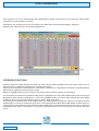
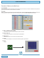
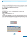
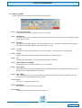
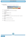
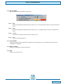
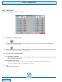
AGRITHERM40WIN
USER MANUAL
applied solution for the application
825B076E
AGRITHERM40WIN
Index
General description
General description
page 3
Installing the programm
Installing the program
page 3
Operating function
OPERATING FUNCTIONS
page 4
Functions buttons and windows
INPUT BOXES
SCROLL BAR
SWITCH KEYS
page 5
page 5
page 5
PC requirements
Minimum PC requirements
PC operating system requirements
page 5
page 5
Program files
Files Making Up the Program
page 5
Description of button
Description of Buttons on the Main Screen
1) SCAN TEMP.
10) PAGE SELECT
11) END
2) ZOOM
3) TURN OFF ALARMS
4) PRINT ALARMS
5) PRINT PROBES
6) PRINT SCREEN
7) SETUP
8) SET TIME TABLE
9) EXTERNAL TEMP.
page 6
page 6
page 13
page 13
page 6
page 7
page 7
page 7
page 7
page 7
page 12
page 13
System setup
7) SETUP
7.1) COM port
7.10) SETUP PROBES
7.10.1) Probe ON Probe OFF
7.10.10) NEXT
7.10.11) PREVIOUS
7.10.12) END
7.10.2) PROBE NO.
7.10.3) MUX NO.
7.10.4) CH. NO.
7.10.5) FROM
7.10.6) TO
Page 2 of 18
page 7
page 8
page 9
page 9
page 9
page 9
page 9
page 9
page 9
page 9
page 9
page 9
7.10.7) DESCRIPTION OF PROBE
7.10.8) MAX. TEMP.
7.10.9) MIN. TEMP.
7.11) SET EXT. TEMP.
7.11.1) Probe ON Probe OFF
7.11.2) PROBE NO.
7.11.3) MUX NO.
7.11.4) PROBE DESCRIPTION
7.11.5) NEXT
7.11.6) PREV.
7.11.7) QUIT
7.12) SET MIN/MAX
7.12.1) MIN
7.12.2) MAX
7.12.3) Cancel
7.12.4) OK
7.13) INIT PROBES
7.14) PRINT CONFIG
7.15) END
7.2) Max. no. of probes
7.3) Language
7.4) Screen Resolution
7.5) Relaies outputs
7.6) Printer
7.7) Floating window
7.8) Menù bar
7.9) History
page 9
page 9
page 9
page 10
page 10
page 10
page 10
page 10
page 10
page 10
page 10
page 11
page 11
page 11
page 11
page 11
page 11
page 11
page 11
page 8
page 8
page 8
page 8
page 8
page 8
page 8
page 8
Time table
8) SET TIME TABLE
8.1) TIMETABLE SCANNING MODE
8.2) CONTINUOUS SCANNING MODE
8.2.1) Continuous scanning
8.2.2) Scanning time interval
8.3) End
page 12
page 12
page 12
page 12
page 12
page 12
Zoom
2) ZOOM
2.1) NEXT PROBE/PREVIOUS PROBE
2.2) Probe / Mux / Ch
2.3) MUX Version
2.4) Trend
2.5) QUIT
page 6
page 6
page 6
page 6
page 6
page 6
Warranty
AGRITHERM40WIN Warranty
page 14
Certificate
AGRITHERM40WIN Factory test certificate
page 14
Address
SGM LEKTRA s.r.l.
page 14
AGRITHERM40WIN
General Description
The function of the PC program Agritherm40Win is to communicate with MUX concentration units via a device with a
RS232/RS485 serial interface (line with two wires + shield). The RS485 serial line is connected in parallel to all the MUX
units in the system and the ID number of the MUX unit will enable the Master (PC) to communicate with one of the Slaves
(MUX).
The MUX units are electronic boards that detect the signal emitted by the sensors of the Probes and convert it into
temperature.
The temperature is measured by means of PT100, NI100 or NI10 (to order).
Each MUX unit can support a maximum of 8 probes.
MUX type A up to 4 measuring sensor points
MUX type C up to 8 measuring sensor points
MUX type D up to 12 measuring sensor points
If the MUX unit is of the B type, the maximum number of probes is 16 with a maximum of 4 sensor points.
Installing the Program
In most cases, the Agritherm 40 Win program is installed directly by S.G.M. LEKTRA, otherwise the procedure indicated
below should be followed.
Insert Disk 1/1 in floppy disk drive A. Using Windows Explorer, select the floppy disk drive and click on the SETUP
(Application) icon.
You will then be prompted to create the folder (we recommend you use the default) in which the program is to be installed
and then press Finish to continue.
When prompted to do so, insert Disk 2/2 in the floppy disk drive, than click on OK to continue and, once the operation has
been completed, click on OK again.
Page 3 of 18
AGRITHERM40WIN
If the program is to be run automatically when Windows© is started, simply create a link inside the autorun folder
(operation to be performed by an expert).
Alternatively, the program may be run by clicking on the Start button and selecting Programs, Agritherm,
Agritherm.exe, which will have the following appearance.
Fig.1
OPERATING FUNCTIONS
When the Agritherm 40 Win program is started, the video screen printed is displayed. This is the main video screen on
which 9 probes are displayed vertically with 12 temperature points.
At the top of each probe is a description of it consisting of a maximum of 7 alphanumeric characters (excluding spaces)
which may be changed as desired (via the setup).
Below the ALARM PAGE row is the number of the video screens containing probes in alarm status.
For each probe, the maximum temperature alarm points are displayed in a colour with a RED border, while the minimum
temperature alarm points are displayed in a colour with a GREEN border. The colour YELLOW with the word “EEEE”
indicates a lack of communication between the PC and the MUX unit polled.
In the bottom far left-hand corner of the display there is a small window indicating the number of the probe currently
polled and then, moving on towards the right, there is the transmission/reception alarm LED (blinks red when there is a
communication alarm) followed by the temperature alarm LED which blinks red when at least one minimum or maximum
temperature probe alarm is in progress. In the bottom right-hand corner there is the key (red) for selecting the video
screen.
Page 4 of 18
AGRITHERM40WIN
SCROLL BAR:
These types of keys are represented by two arrows set vertically (one up arrow and one down arrow) on the left plus a
square on the right (see screen selection key in figure 1).
The square on the right shows the number on which the scroll bar is currently set (for example, the number of the current
video screen). This number can be increased or decreased by pressing the up arrow or down arrow keys on the keyboard, or by clicking the mouse button on the arrow symbols situated on the left, or by pressing the space bar and
selecting a number on the vertical bar which appears when you press the enter key or click on the number chosen with
the mouse.
SWITCH KEYS:
These types of input objects may only be set ON or OFF using the up arrow key (ON) and down arrow key (OFF) on the
keyboard or by clicking the mouse button directly on the ON/OFF cursor.
INPUT BOXES:
These boxes are used to enter numeric parameters or alphanumeric descriptions from the keyboard. Having entered the
data inside these boxes, you must press the enter key if you want the data entered actually to be brought into effect.
Minimum PC requirements
80486 or similar processor with math coprocessor.
One 3.5” 1.44 Mbyte floppy disk drive.
One VGA colour monitor.
One hard disk with a minimum of 10 Mbytes of free space. (more if a history file is required)
One mouse
One free serial port (COM2) for the RS-485 bus connection and MUX unit connection.
One 80-column black and white or colour printer
PC operating system requirements
Microsoft Windows© 95, 98, 98SE, ME, 2000
The program is not designed for use in MS-DOS environments or multi-user networks of any kind.
Files Making Up the Program
The Agritherm 40 Win program is made up of the following files.
Agriterm.exe
Panel.uir config.log tab_conf.log minimax.log parms.dat temp.dat
Page 5 of 18
AGRITHERM40WIN
Description of Buttons on the Main Screen
1 ) SCAN TEMP.:
Forces a read scan of all the temperature probes. During the probe read scan, this button is disabled as the operation is
performed automatically (see also Setting the Timetable)
2 ) ZOOM:
Shows in real time the measuring points of the selected probe. This a purely diagnostic function, which is normally used
during inspections made to test the general functioning of the system by S.G.M. LEKTRA technical staff.
2.1) NEXT PROBE/PREVIOUS PROBE:
The buttons are used to browse through the probes connected.
2.2) Probe / Mux / Ch:
In this windows is possible to select directly the probe address.
2.3) MUX Version:
Identifies the version of the firmware of the MUX scanned.
2.4) Trend:
The trend icon displays one of the points read with a graphic representation.
2.5) QUIT
Escape.
Page 6 of 18
AGRITHERM40WIN
3 ) TURN OFF ALARMS:
Turns off relays (optional relay output board), alarms.
If the program is set on the basis of a timetable and not in continuous mode, at the end of the scanning cycle, any alarms
detected will result in static switching of the relay outputs Max Relay 1, Min Relay 1, GEN, pulsed switching on Max
Relay 2, Min Relay 2 represented graphically on the main screen. This command has an immediate effect on outputs
Max Relay 1, Min Relay 1, GEN while Max Relay 2 and Min Relay 2 will continue to be energized for 1 second at the end
of the scanning cycle even if the timetable follows continuous operating mode.
4 ) PRINT ALARMS:
Prints all the probes in alarm status detected during the last scan as being in maximum or minimum temperature alarm
status.
5 ) PRINT PROBES:
Prints all the probes detected during the last scan, irrespective of whether they are in alarm status or not.
6 ) PRINT SCREEN:
Prints the video screen currently displayed (hard copy)
7 ) SETUP:
Provides access to the program parameter setup and plant configuration. It should only be used when strictly necessary.
The settings are made at the S.G.M. LEKRA laboratories on the basis of specifications made directly by the customer to
enable him to start using the entire supply immediately.
You will be prompted to enter the password and we recommend you avoid revealing this password to unauthorized staff.
On this screen, all the parameters set initially can be completely changed so we recommend you make a copy, in another
directory of the PC, of the following files: Parms.dat, Temp.dat, Config.log, Tab_conf.log, which are present in the
installation directory (Agritherm) or take those on Disk 2/2 in the BACKUP folder.
Enter the password, type THERMO and then press OK. The following screen will appear.
Page 7 of 18
AGRITHERM40WIN
7.1)
COM port:
Selects the serial port through which the program will communicate with the MUX units via the RS232/RS485
interface device. Port COM2 is normally set.
7.2)
Max. no. of probes:
Represents the maximum number of probes present on the video screens, one screen may contain a
maximum of 9 probes.
7.3)
Language:
Selects the desired language GB = English, IT = Italian, FR = French.
7.4)
Screen Resolution:
Sets the maximum graphic resolution. The normal setting is 800x600 dpi, the optimum resolution for
14-15” SVGA monitors while 640x480dpi is recommended for 14” VGA monitors and 1024x768dpi for large
monitors such as 17-19”. The graphic setting of the PC must correspond to the one to be obtained from the
Agritherm 40 Win program. Should the exit commands disappear due to incorrect setting, simply press the
ESC key to terminate the program, set the resolution to the maximum (1024 x 768) and restart
Agritherm40Win.
7.5)
Relaies outputs:
The Enable/Disable relay outputs switch (optional 8-relay board).
7.6)
Printer:
The Enable/Disable printer switch. The program is supported by the operating system so it works with
any printer, whether local or installed in a network.
7.7)
Floating window:
The switch Enables/Disables the buttons on the top bar, so when the Disable function is set, Agritherm40Win
cannot be minimized. This function may be set as desired.
7.8)
Menù bar:
The Enable/Disable switch changes the setting of the buttons on the main screen, which will appear as a
drop-down menu. It may be set as desired.
7.9)
History:
The ON OFF switch in the ON position is only operative if the operating mode (see timetable) is based on a
timetable and not continuous, at each time set ON, after the scan set, the program creates a backlog.dat file
containing the historical data in the Backlog folder where Agritherm40Win was installed, normally Agritherm
Backlog. This file gradually increases in size as time passes and may be used at the customer’s will
(see figure 1).
Page 8 of 18
AGRITHERM40WIN
7.10) SETUP PROBES:
Probe setup screen, it is used to set all the probe setup values.
7.10.1)
Probe ON Probe OFF:
The ON switch enables the probe in question to be read.
7.10.2)
PROBE NO.:
Indicates the progressive display position of the probe on the main screen, which may display 9 probes
(columns) per screen.
7.10.3)
MUX NO.:
Indicates the identifying address, UID (Unit Identifier Device), of the MUX unit with which the probe is
associated (see wiring diagrams). Enter values from 1 to 62.
7.10.4)
CH. NO.:
Indicates the channel of the MUX unit to which the probe is connected (see wiring diagrams).
7.10.5)
FROM:
Initial number from which the probe is made of MUX A, C, D sensor points.
7.10.6)
TO:
Final number (total number of points) of which the probe is made up.
7.10.7)
DESCRIPTION OF PROBE:
Enter alphanumeric text without spaces, up to 7 characters.
7.10.8)
MAX. TEMP.:
Sets individually the maximum temperature threshold beyond which (if exceeded during the scan) the
probe point will be displayed with a red border.
7.10.9)
MIN. TEMP.:
Sets individually the minimum temperature threshold below which (if exceeded during the scan) the
probe point will be displayed with a green border.
7.10.10) NEXT:
Moves on to program the next probe.
7.10.11) PREVIOUS:
Moves back to program the previous probe.
7.10.12) END:
Closes this session and returns to the setup screen.
Page 9 of 18
AGRITHERM40WIN
7.11) SET EXT. TEMP.
External probe setup screen with a maximum of 40 probes (1 per MUX unit)
7.11.1)
Probe ON Probe OFF:
The ON OFF switch sets the probe ON (see wiring diagrams).
7.11.2)
PROBE NO.:
Progressive number from 1 to 40.
7.11.3)
MUX NO.:
Progressive number from 1 to 40.
7.11.4)
PROBE DESCRIPTION:
External probe ID field, enter alphanumeric text without spaces (maximum 7 characters).
7.11.5)
NEXT:
Moves on to program the next probe.
7.11.6)
PREV.:
Moves back to program the previous probe.
7.11.7)
QUIT:
Closes this session and returns to the setup screen.
Page 10 of 18
AGRITHERM40WIN
7.12) SET MIN/MAX:
Sets the temperature thresholds for all probes
7.12.1)
MIN:
Minimum temperature threshold Enter values from –10 99 below these values, the green alarm will
occur.
7.12.2)
MAX:
Maximum temperature threshold Enter values from –10 99 below these values, the red alarm will
occur.
7.12.3)
Cancel:
Cancels the operation and returns to the setup screen.
7.12.4)
OK:
Confirms the parameters set.
7.13) INIT PROBES:
Initializes all the probes (cancels all the parameters of the probes set), it is used when the plant is to be
completely reconfigured
7.14) PRINT CONFIG:
Prints the configuration of all the probes set.
7.15) END:
Returns to the main screen.
Page 11 of 18
AGRITHERM40WIN
8) SET TIME TABLE:
Sets scanning mode: timetable or continuous
8.1)
TIMETABLE SCANNING MODE
Using the ON and OFF switches located under this icon you can set the time at which the temperatures
are to be scanned automatically.
Using the ON and OFF switches located under this icon, you can program the automatic printing of all probes for
the time with which the start of the scan is associated.
8.2)
CONTINUOUS SCANNING MODE
8.2.1) Continuous scanning:
When the ON OFF switch is set to ON, the program will no longer consider the time settings and will read
the temperatures continuously.
8.2.2) Scanning time interval:
Time interval (in minutes) when you wish to include a pause between one scan and the next, in
continuous operating mode, enter values from 1 to 30.
8.3)
End:
Returns to the main screen.
Page 12 of 18
AGRITHERM40WIN
9)
EXTERNAL TEMP.:
External probe reading screen, function available if external probes have been connected and the MUX
unit has been set up for their connection.
10) PAGE SELECT:
Used to select the screen page.
11 ) END:
Used to exit from the AGRITHERM 40 Win program. From this moment on, no temperature will be updated and
the history file will be interrupted. It is however possible to minimize the program to be able to use other
programs while Agritherm 40 Win continues to run.
Page 13 of 18
AGRITHERM40WIN Warranty
Products supplied by SGM LEKTRA are guaranteed for a period of 12 (twelve) months from delivery date according
to the conditions specified in our sale conditions document. SGM LEKTRA can choose to repair or replace the Product.
If the Product is repaired it will mantein the original term of guarantee, whereas if the Product is replaced it will have 12
(twelve) months of guarantee. The warranty will be null if the Client modifies, repair or uses the Products for other
purposes than the normal conditions foreseen by instructions or Contract. In no circumstances shall SGM LEKTRA be
liable for direct, indirect or consequiential or other loss or damage whether caused by negligence on the part of the
company or its employees or otherwise howsoever arising out of defective goods.
AGRITHERM40WIN Factory test certificate
In conformity to the company and ceck procedure I certify that the equipment:
AGRITHERM40WIN....................
part nb. ......................
is conform to the technical requirements on Technical Data and it is made in conformity to the SGM-LEKTRA procedure
Quality Control Managerl:
Production and ceck date:
.................................
.................................
SGM LEKTRA s.r.l.
SGM LEKTRA s.r.l.
Via Papa Giovanni XXIII, 49
20090 Rodano (Milano)
tel. ++39 0295328257 r.a.
fax ++39 0295328321
e-mail: [email protected]
web:
www.sgm-lektra.com
documentation subject to technical change with no prior warning

![M80(20110610)a [转换]](http://vs1.manualzilla.com/store/data/006273150_1-6bbe97485a95500cb3e20379f02d1514-150x150.png)