1
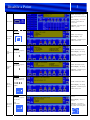
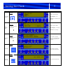
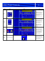
ZP3 Operator & Maintenance Manual Version 1 Introduction Thank you for selecting Clymac Ltd. Clymac can provide maintenance for the system, emergency call out, telephone support and any modifications required during the life time of the ZP3 system. To ensure the ZP3 system continues to operate without false alarm or fault the system will require regular maintenance from a qualified engineer. If you decide to choose Clymac as the maintenance provider we can offer the following benefits; Reduced call out charges Clymac Engineers carry most spares to enable first time fix Clymac have the largest stock of spares in the UK Immediate out of hours telephone response & engineer on site in 8 hours Discounts for long term agreements We will be happy to provide a quotation for maintenance, please call & ask for maintenance sales Contents Reference information................................................................................................................1 System in Alarm…………………………………….…………………………………………2 Disable a Point………………………………………………………………………………...3 Silencing the Fault Buzzer…………………………………………………………………….4 Setting the Clock………………………………………………………………………………5 Other Panel Controls…………………………………………………………………..………6 Your Responsibility………………………………………………………………….………..7 Log Book……...………………………………………………………………………………8 Data Sheets & Device Labels………...…………………………………..…………………...9 Reference Information Address of protected premises: 1 ………………………………………………………… ………………………………………………………… ………………………………………………………… ………………………………………………………… Responsible person: ……………………………………………………….. The system was designed by: ………………………………………………………. The system was installed by: ………………………………………………………. The system was commissioned by: ………………………………………………………. The system was accepted by: ………………………………………………………. Verification was undertaken by: ………………………………………………………. Maintenance Company: ………………………………………………………. Emergency Telephone Numbers: 01509 232651 (Normal working hours) 07659 134363 (Outside normal hours) Maximum attendance time for a maintenance technician is: Major Fault - 8 Hours Minor Fault - 24 Hours Expendable components replacement list: Panel Batteries – 4 years from commissioning date PSU Batteries – 4 years from commissioning date HSSD Filter – 1 year from commissioning data ………………………………………. ………………………………………. ………………………………………. System in Alarm Event Action 2 Panel Notes LCD = Zone No, text and time of event Fire Initiate fire safety strategy Status Display = Red Active sounders, remote alarm & control O/P Objective’s = Ensure safety, find the source & silence/ reset the system LCD = Point address, type, text, time of event, zone No & text Status Display = No change Fire - Find Source Objective = Locate device & identify cause. MORE buttons denote more fires waiting to be shown see page 7. Also network systems will have panel number detailed. LCD = Enter control key code **** Fire – Silence Alarms Status Display = No change Objective = Enter level 2 access code typically 2000 KEY PAD 1000 followed by; Enter Access code LCD = **** changes to XXXX as user inputs the access code. Once access is granted the system operates a 2 min timer from last button press before it logs the user out. LCD = Zone No & text Mute Buzzer Status Display = Active sounder extinguished and yellow sounders silenced Objective = ensure the source will not cause the system to retrigger. This can be achieved by disabling the point address LCD = System return to normal Reset Status Display = returns to normal Objective = record incident in the log book Disable a Point Event Action 3 Panel Notes LCD = Point address, type, text, time of event, zone No & text Status Display = Red Active sounders, remote alarm & control O/P False Alarm Objective = Record the point address e.g. 1001 Key Pad LCD = Top menu page Status Display = N/A View Menu Selection Objective = Disable the point address before reset Key Pad Enter Maintenance Menu LCD = Maintenance Menu On the key pad press the number: 2 Status Display = No change Objective = Disable the point address before reset Key Pad Enter edit disable menu On the key pad press the number: LCD = Maintenance Menu Status Display = No change 1 Objective = Disable the point address before reset Key Pad On the key pad enter the point address e.g.: LCD = Maintenance Menu Specify point to be disabled 1001 Objective = Disable the point address before reset Key Pad On the key pad press the number Specify the point to be disabled Status Display = No change (then) 1 (then) LCD = System return to normal Status Display = returns to normal Objective = Save data by pressing the following on the key pad & record in log book: Silencing the Fault Buzzer Event Action 4 Panel Notes LCD = Zone No, text and time of event System Fault Investigate the nature of the fault Status Display = Yellow Faulty Zone & point Objective’s = Record Fault in log book & action repair LCD = Point address, type, text, time of event, zone No & text Find source Status Display = No change Objective = Locate device & identify any obvious cause e.g. device removed or water leak LCD = N/A Status Display = No change Silence buzzer Objective = Ensure the fault is attended to & leave the fault on screen i.e. do not reset or disable fault Setting the Clock Event Action 5 Panel Notes Key Pad LCD = Top menu page Status Display = N/A View Menu Selection Objective = Set the time, day and date Key Pad Enter Operator Menu On the key pad press the number: 1 LCD = Operator Menu Status Display = No change Objective = No Change Key Pad Enter date menu On the key pad press the number: 1 Set the date by entering dd/mm/yyyy and then adjust the day by using the arrow up/down Key Pad Set the time by entering hh:mm followed by enter Enter time Key Pad Return to home page Note new time, date & day Other Panel Controls Event Action 6 Panel Notes Illuminate when more information is waiting to be shown. Press either button to view the next event. The events will scroll around with each push of the corresponding more button. More button Used to enable previously disabled sounders quickly to facilitate an evacuation during routine maintenance. If pressed with access code when the system is in fire the alarms will activate. Restore disabled alarm Other outputs such as lifts/Gas/HVAC and Fire Brigade will not have activated Events are prioritised with any fire event having the highest priority. However, to view any type of event press the corresponding button to view zonal information followed by view points for further information. Viewing different event types i.e. Fire, Fault, Disabled Controls On/Off switch Turn to the off position When this is in the “off” position the controls detailed will be isolated to prevent unauthorised operation. Your Responsibility 7 Ensure a maintenance contract is in place complying with the recommendations of BS 5839 Part 1 Section 6 Ensure the system is tested with a different Manual Call Point (MCP) each week in a way that demonstrates to all staff what the Fire Alarm sounds like. In carrying out this test the basic function of the system is also tested. Maintain a system log book recording; Responsible person & maintenance provider details The weekly test – point address, date, time & name False alarms – date, time, address/location, category *, reason, action taken and name Details of service/repair Faults – date, time, address/location, type of fault, reason, action taken and name Visually check the panel daily Ensure other users of the system are familiar with the system Arrange for suitable investigations when the system false alarms Manage the system & activities in the building it protects by; Ensuring visiting contractors are aware of the automatic detection & that method statements include protecting the automatic detector from any pollutants that may trigger a false alarm. This should include a temporary dust cover and point disablement Notification to staff and alarm receiving centres (RedCare) when the system is due to be tested and/or maintained. Keep all MCP’s free from any obstruction & on show Keep 500mm clear space in all directions around automatic detectors Give consideration to the fire alarm system when the building is modified. The objective of the fire alarm can be compromised by adding/removing walls/doors. Also, any change in use may require change of and/or additional detectors to ensure minimal false alarms. Ensure As-Fitted drawings and detailed records at the end of this manual are kept up to date. Ensure suitable quantities of replacement MCP elements/keys are kept on site. * Categories of false alarms are; Unwanted – steam, smoke, dust, insects etc and human error Unknown/equipment – No obvious reason could be faulty equipment Malicious Good intent Log Book DATE TIME 8 DETAILS ZONE DEVICE INITIALS Log Book DATE TIME 8 DETAILS ZONE DEVICE INITIALS Log Book DATE TIME 8 DETAILS ZONE DEVICE INITIALS Data Sheets & Device Labels 9 Included at the end of this manual are standard data sheets for the equipment installed and finally a print out detailing the zone & point text labels. This information should be cross referenced with the As-Fits for accuracy. Cloudway Court Belton Road Loughborough LE11 1LW Tel: 01509 232651 Fax: 01509 232665 E-mail [email protected]