1
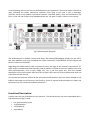
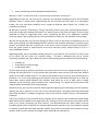
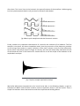
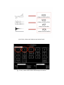
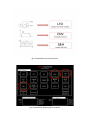
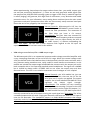
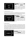
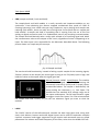
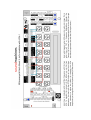
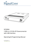
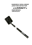
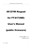
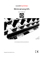
soundmachines NS1nanosynth User's Manual V1.0 November 2015 by Davide Mancini Designed and crafted in Italy IMPORTANT INFORMATION: Care and Feeding: Please be aware that only 5V power supplies are allowed. We have protections on the device DC jack but it won't resist indefinitely against higher voltages!!! If you didn't purchase the bottom cover, please avoid touching the electronics on the bottom layer of the PCB with your hands and avoid the contact of the bottom side with metallic or conductive object that could be on your desk (pens, jacks, nail trimmers...) as it can cause a destructive short circuit. Those are really basic indications for the people that are used to Arduinos and similar products (that tipically 'exposes' the circuits and components to the user) but could be less known to a musician or a curious guy like yourself. Do not connect the unit directly with devices (other modular products) that could source voltages greater than 5V signals without external protection. This can lead to malfunctions and eventually break some parts on the NS1nanosynth. Please consider the usage of the NSbridge, our own small adaptation board, when planning to connect to eurorack modules. The NSbridge have integral protection that should cover all the inadvertent application of out of range signals! On this board there are protection for voltages greater than 5V and negative voltages. The patching points on the top side of the board are obviously safe to use and there are no potential damages when you are patching. Take some time with this manual as the universal advices like "don't connect an output to another output" still does apply! Power Supply Specification: • • 5VDC regulated 200mA supply current (1W) Introduction: The NS1nanosynth is a full featured, minimal size, analog modular synthesizer integrated with an Arduino Leonardo (TM) platform. Out of the box the Arduino is programmed with a USB MIDI to CV firmware that you can use to control your NS1 with your PC/MAC or iPAD etc... The NS1nanosynth employs a plethora of analog modules to allow complex soundscape creation, instruments analog emulation, and noise/hardcore/annoying stuff. With its full analog signal path, that includes a 1V/oct multi waveforms VCO, a 12dB/oct lowpass and bandpass resonant VCF and a overdrivable standard exponential response VCA, the NS1 could be used alone or integrated with other instruments, circuits and devices, to build an articulated modular patch, augmented by the potential 'virtual modules' that you can code on the Arduino. A great feature of the architecture of the NS1nanosynth is the ribbon controller with the hold function, that could allow you to use the synth without any external controller, making it a really ultra portable modular synth! The NS1nanosynth additionally contains the following modules: two dual waveform LFOs, one loopable ADSR envelope, two attenuators, two pot controllers and a dozen “micro” modules like mixers, multiples, sample and hold, sum/sub blocks, inverters, logic or, and, nand, analog voltage dividers, clock dividers, fixed voltage generators and several ‘sensor blocks’. fig.1 NS1nanosynth overall architecture In the following picture you can see the floorplan of the synthesizer. The sound 'flows' from left to right, following the classic subtractive synthesis chain (that in this case is just a 'topologic' reminder, being a full modular synthesizer without normalled paths). From the oscillator to the filter, to the vca and finally to the headphone/line out, the path is clearly visible on the overlay: fig.2 NS1nanosynth floorplan The NS1nanosynth is divided in three main areas: the Arduino/DAC/digipot headers (on the LEFT), the main Modular synth area (including the ribbon controller) in the MIDDLE and the Digital and Sensor headers on the RIGHT. Regarding the middle section take a moment to learn the logic of the module's connections. It's quite simple to understand that the lower row of headers is linked to the main modules (the ones with potentiometers, such as VCO, ADSR, VCF, etc...) and the upper one, with the notable expception of the LFOs output (SQU and TRI, for both LFOs) are the utility modules that does not have direct manual control. This manual will describe in detail all the aforementioned modules, the basic sketch loaded on the Arduino Leonardo and its functions and finally a series of patches and techniques to obtain the maximum from this small but powerful machine!!!! Functional Description: A quick word on the philosophy of this machine. The NS1nanosynth has been developed with a few important things in mind: • • • • 0-‐a good sounding synth 1-‐completeness 2-‐affordability 3-‐portability • 4-‐easy interfacing to DIY and digital-‐based platforms We won't "push" on the point-‐zero, as you will have to discover and enjoy it! Regarding the point #1 you can see for yourself: we crammed something like 25 full functional modules, some of which quite sophisticated like the full-‐featured VCO, with its 4 waveforms output, the sync and pwm capability and a couple of different noise outputs on a 22x8,5 cm printed circuit board! #2 We then cut all the "unnecessary" things, like knobs, panels, case, jacks, everything that doesn't have much to do with sound and functions, to optimize costs and reach our target. In the end we obtained an order of magnitude lower price, comparing the NS1 to an equivalent standard eurorack system. We're talking about a two thousand euro value in a two hundred euro package. We are not saying that are the same thing and they'll never be but what we wanted to do is to open up the feeling, the methodology and the results of the modular synthesizer's world to many persons as possible, from the curious ones, to the critics, to the students, to the guys that doesn't have the space, money or committment to start an eurorack system without trying it first in a more affordable format! Regarding the #3, you are probably holding one NS1 in your palm as you read this so, what I have to say more? Oh yes, there are a couple things.... The NS1 is powered with just a simple, universally available, 5V input! Wherever you are you probably have at hand one of the following: • • • an USB port A smarthpone USB recharger A USB power bank This last point bring us quickly and directly to the point #4, the one that, along with NS1's price, is pushing the NS1nanosynth in a big market: We choosed to make ALL the CVs (and most AUDIO) signals on the NS1 unipolar and 5V. This aspect, that could be seen by many synth enthusiast as a limitation, it is in fact a big opening to the world of the many possibilities brought to us from the latest open source digital platform like Arduino. And there are a lot of ways (and a couple modules :)) that can put a great remedy to this "shortcoming". In a digital world, we have to be ready to adapt and modify our analog heritage. Needless to say, we are really proud of endorsing and integrating this technology into our product, opening up many scenarios to the users of the NS1nanosynth, including community-‐developed alternative firmwares, hardware integration with all the arduino shields, sensors and companion products! A last 'non technical' note is related to the inception of this product. We would like to thank Sugar Music (NicF) and the Maker Faire organisation for inviting us to the Rome event of Oct2015 and to push us to 'invent' something for that occasion. The NS1nanosynth has many fathers and the incredibly quick time to market of this product (development started in July, first products shipped in October!) would not have been possible without the passion, hard work and crazyness of many persons. And my wife, without her support there would be no nanosynth!!! A synthesis primer: For the people that doesn't came from synthesis or from music production, in the next two pages you will find some basic concepts that will be extremely useful to better understand the following chapter and to enjoy this instrument. Let's start by defining the main characteristics of 'sound'. Among the few definition of sound, stands the one that I like more: it's the perceptive phenomenon that our earing subsystem triggers when more or less repetitive variation in the density of the air reach our inner ear organs. This is not the only definition nor the most precise one, but as I said, I like it enough to write it here. A sound is then characterized by a handful of 'parameters', or qualities. The optimal subset, for what we are going to explain in the following pages (again, far for being complete under a scientific POV) is: • • • pitch timbre loudness Those are neither static qualities, nor the only ones, but they adds up nicely in this contest. Consider, for starter, that the timbre of a sound could easily modify the pitch until unrecognizable... So, Pitch is the 'tone' of the sound, what we associate with the concept of 'note'. Not all sounds have a defined pitch, think about the sound of the waves crashing on the beach... In a more harmonic enviroment, such as a techno-‐trance song, the pitch is responsible, for example, of the bassline that supports the harmonic progression of the piece itself. Do Re Mi Fa Sol La Si, in Italian. fig.3 Musical octaves and their pitch The second 'parameter', the timbre, is the microscopic 'shape' of the sounds. Microscopic on a time scale. Mainly we are talking about the waveform and its dynamic transformations... Think about the timbre of a cello, in contrast to the one of a human soprano, or that of a Strato passing through a fuzz pedal with almost dead batteries... One of the first 'missions' of the electronic musical instruments was the simulation or emulation of traditional musical instruments. Where a triangle wave resemble, with a touch of vibrato (pitch modulation) the voice of a soprano, the narrow pulse rectangular wave could trigger in our brain a certain association with the nasal sound of an oboe. The 'secret' here is the harmonic (or spectral) content of the waveform. Without going into hairy mathematical details I will just leave a reference table below: fig.4 Basic synth waveforms and their harmonic content Finally, another very important characteristic of a sound is the evolution of its loudness. The first example is the piano. An almost immediate attack, that the percussion of the hammers provokes on the strings, leave space to a quick 'reduction' of the note's volume in the first few millieconds. At this point, if the player keeps his finger on the key, the note will slowly fade, otherwise the end of the sound will come in few tenths of a second. We like to call the shape of the loudness as the amplitude's envelope. fig. 5 A piano sample amplitude envelope We briefly defined the characteristics of a 'sound' to be able, in the following chapter, to give an indication of WHAT kind of blocks could be used to implement those in the real world... Now a simple link between those characteristics and their implemented building blocks: fig. 6 Pitch, timbre and loudness equivalent blocks fig. 7 Pitch, timbre and loudness NS1nanosynth modules fig. 8 modulations equivalent blocks fig. 9 modulation NS1nanosynth modules Starting from this terminology and structure we can play a little with the concept of subtractive synthesis. The basic concept is that, starting with an (one or more) oscillator, by putting the output tone into a some kind of filter device and then into a controlled amplifier, we can basically synthesize 'every' existing sound, emulating acoustic instruments and creating new sounds. Given that the emulation of acoustic instruments is not our main aim (since many years now, is not anyone's aim :)) we will concentrate on creating sounds and noises that can adapt well with every kind of electronic music production, from drone, to techno, passing through glitch and ambient... At the end of this manual, the patch sheets will guide you through many examples that will space from the classic monosynth lead sounds to 303-‐like squelchy basslines, to percussive, drone and self-‐generating soundscapes... NS1nanosynth modules: • VCO voltage controlled oscillator The voltage controlled oscillator is the heart of any analog synthesizer. Wheter you look for melodic or noise content you'll need an oscillator to start whit. The signal coming out of the oscillator is characterized by its pitch and the shape of the waveform. The NS1 VCO is capable of tracking through the V/oct standard (that states that, to every 1V increases in control voltage, the oscillatore will increase the pitch of one musical octave) five octaves. At the end of the manual the (rather simple) procedure to re-‐calibrate the VCO is described. Manual controls: The VCO has a TUNE knob that sets the oscillator's frequency. This frequency is summed with the control voltages coming from other modules into the inputs. The PWM knob is setting, along with the relevant CV input, the puls width of the rectangular (SQU) wave, from 0% to 95%. Input/Output: The NS1nanosynth VCO has one V/oct CV input for tuning duties (in the standard firmware you can connect this pin to DAC0 pin of the Arduino section to derive the pitch coming from MIDI), another CV input (not linear, but not V/oct either, to permit you to have more subtle modulations), a PWM input (that sums up with the knob's position) and the SYNC input to reset the saw core with positive going signals. The waveforms of the oscillator (saw, triangle, square and sub-‐osc) are all available at its outputs along with white and pink noise sources. Tech Specs: Technically speaking all the waveforms have an amplitude of 5 to 6 Volts and are unipolar (i.e. not negative). • VCF voltage controller filter: The filter of the NS1nanosynth is a classic OTA (operational transconductance amplifier) 2nd order (two poles) resonant filter (12dB/oct) with low pass and bandpass outputs. Raising the resonance the filter adds 'ringing' and harmonics to the cutoff frequency, until it goes into unstable and pretty wild self-‐oscillation. Self oscillations starts at about three o'clock knob position and there is a very 'critical' position of the knob beneath 'nice and warm analog resonance' and 'fricking weird tones' behaviour. Play it at your own risk and, when experimenting, keep always the output volume lower than you would, respect your ear and your monitoring equipment! ;-‐). Filters are not only good with audio signals (like the output of the VCO) but also inputting a gate or trigger to the filter (in modular lingo this is called 'pinging') will generate, with high level of resonances, a very distintive and usable percussive tone. For your infomation, many analog drum machines have the main sound generators made with (sometimes more than one concurrently used) resonant band pass filters that are in fact, pinged by the instrument trigger. Manual Controls: NS1nanosynth's VCF has the classic FREQ and RESONANCE control knobs to control the filter parameters. The resonance of the filter does not have a CV control. Input/Output: The filter have two summed CV control of the cutoff frequency and two summed audio inputs. You can input directly the VCO to the audio inputs (-‐-‐>) without overloading the filter. Tech Specs: The VCF has a linear response with regards to the CV input. No exponential converter has been used in this module. • VCA voltage controlled amplifier + AMP output stage: The NS1nanosynth VCA is an exponential response audio voltage controlled amplifier with a very interesting distortion at the end of the CV range. When the control voltage reach 4.5V (the INITIAL knob a little before three o'clock position) the VCA starts to distort with a very pleasant analog overdrive tone, really usable in some bassline environments. In this module we include the output stage called AMP that connects with the output jack and is both compatile with a line input and standard stereo headphones. The signal out is MONO but it should be always used a STEREO JACK to not stress the output amp and hear distorted tones. This VCA is not suited to attenutate control voltages as is AC coupled. Manual Controls: the VCA module has just one knob, labelled INITIAL, that sets the CV for the VCA when no CV inputs are applied. The output amplifier has a knob labelled VOLUME OUT that regulates the output signal strength. Input/Output: The module has two summing audio inputs, two summing CV input for the VCA gain (attenuation) and a single VCA output (-‐-‐>). The AMP module has only the AMP input that is normally connected to the VCA output to bring the synth signal out. Tech Specs: The VCA is a standard exponential VCA with a high gain distortion characteristic when the CV input is near the 5V saturation. The headphone output is a DUAL MONO connector that always should be used with stereo cables to avoid shorting the right channel with the ground. This will not damage the output but could result in audio unwanted distortions! • ADSR envelope generator: The ADSR module is a versatile four stage envelope generator with manual controllable Attack, Decay, Sustain and Release stages. The envelope generatore could also implement a 'gated' looped mode where the output will cycle through the stages while the GATE input is HIGH. To obtain the looping envelope the sustain knob should to be put to zero. Another interesting option is the ability to have a second 'timing' capacitor for the ADSR stages that lengthen the times fivefold. Manual Controls: The module has individual controls for Attack, Decay, Sustain and Release stages and a LED that follows the OUT voltage. It's a clear indication of the evolution of the envelope during time. Input/Output: There two gate inputs (OR'ed) and two identical OUT signals. To use the LOOP and SLOW functions the user have to 'short' the relative patch points as indicated on the board. Tech Specs: The ADSR output level goes, as the other modulators on the NS1nanosynth, from 0 to 5V. If you connect this directly (i.e. without attenuation) to the VCA CV input you will obtain, as designed, an overdrive in the highest 0.5V zone. You can use the ATTENS or the CVDIV modules to adapt this level to the VCA. This is normally indicated in many hardwired synthesizers as "EG AMOUNT" or "ENVELOPE AMOUNT". • LFO low frequency oscillator: NS1nanosynth have two identical LFOs with triangular and square output waves. The frequency goes from a slow modulating 0.4 Hz to an audio rate 160Hz, controllable through the FREQ1/2 knob of each LFO. There are doubled outputs for each waveform. Manual Controls: the FREQ1 and FREQ2 knobs sets the LFO frequency for each LFO. The individual LED shows the triangular output level of the LFO in real time. Input/Output: There triangular (TRI) and square (SQU) waves output for each LFO, the signals are simply doubled on the patch points. TechSpecs: The waveforms at the output of this module goes from 0 to 5V. • ATTENs passive attenuators: There are two passive attenuators on the NS1nanosynth, each controlled by a knob (ATTEN1 and ATTEN2). The signal is attenuated to zero when the knob is in the 7 o'clock position. Manual Controls: ATTEN1 and ATTEN2. Input Output: There two inputs and two outputs for each attenuator. Tech Specs: consider that, with regard to impedances, the attenuator is passive and parallel configuration of input and output signals (i.e. more than one signal at the input) will modify the relative impedances as well. This is not dangerous at all but can lead to different results than the one you imagined! • CVGEN (CONTROLLERS): CV generators: There are two active CV generators on the NS1nanosynth. Those voltage sources, controlled by their relevant knobs (CTRL1 and CTRL2) simply generates at the output a voltage from 0 to 5V. It could be used for any purpose including connected to the Arduino analog pins to dial parameters and configurations into an alternative firmware. Manual Controls: the two knobs CTRL1 and CTRL2. Input/Output: The module have two outputs C1 and C2. Tech Specs: The CVGEN/CONTROLLERS module has buffered outputs. This means that you can hook up the output C1 to different inputs (using a mult) without degradating its qualitites. General concept: a buffered output will not suffer from a wide range of input impedances adn could also drive small loads like LEDs, headphones etc... • RIBBON CONTROLLER: One of the most immediate and intriguing features of the NS1nanosynth is its Ribbon Controller, a 100mm resistive linear potentiometer that, through a specialized circuitry becomes a fun to use playing interface. The patch section of the Ribbon Controller (top right, near the robot!) generates a couple of identical GATE signals when you press on the ribbon and presents two different CV outputs (that shares the range, from 0 to 5V going from left to right on the ribbon). The first one, CV, is the exact information about your finger's position on the ribbon, including the return-‐to-‐zero when you lift your finger. The HLD is holding the voltage with an internal S&H to allow you to use release times on the ADSR (for example) and other techniques. Manual Controls: the Ribbon! There is also an LED that lights up when a GATE is detected (finger down). Input/Output: GATE, goes high when the finger is on the ribbon. CV outputs 0 to 5V (from left to right), HLD outputs 0 to 5V even when the finger is lifted from the ribbon. Tech Specs: To obtain the HOLD function we had to insert a little time constant in the circuit and this leads to an audible 'slew' when you drive, for example, the pitch of a VCO .Is it important to lift the finger quick when you want to minimize this effect... You will learn this in no time :). A quick hint if you want to play 'theremin' style with the ribbon: reduce the range of the ribbon (remember, 5 Volts is equal to 5 octaves!!!) with an attenuator and set the starting freq of the VCO with its TUNE knob. The ribbon is really expressive when you learn to use it correctly and subtle variations in the finger position results in pleasant (or NOT) modulations. • MIXER (1:1 and 1:3): Those humble modules are actually, together with the sum/sub, one of the most versatile ones in the NS1nanosynth, with regards to their standard, intended behaviour. As we choose to mantain all the CVs and signals in general unipolar and 0 to 5V, the MIXERs could serve many purposes. Punk VCAs, waveshapers and switches! The 'secret' is the 'saturating voltage' of the mixers and sum/sub blocks. We choose to power those circuits with 5V and as you may know (or not, given some thread in some famous forums!) the voltage at the output of a summing static active circuit will NEVER go beyond the power supply rails :). Whit this in mind we designed two simple mixers types, one with the implicit reduction of the input channels to 1/3 of their voltage (hint: attenuation) before summing and the other two mixers with a 1:1 ratio before summing. The first one is clearly identified on the NS1 with "MIX/3" label. The idea behind this /3 was to be able to sum the output waveforms of the VCO (for example TRI+SQU+SAW) without clipping, and then distortin the resulting waveform. The mixers have, in practice, another usable quirky aspect. The 1:3 and 1:1 behaviour is only true when all the channel are used or referred to a known voltage. When you leave unconnected the inputs the mixer will change the gain depending on the number of the used inputs! This could sound complex and awkward but it's just another tool in your toolbox! If you don't want this you can just connect to 0V the unused inputs! Manual Controls: NONE Input/Output: three channel inputs, one output. Tech Specs: already discussed! • MULT multiples: Not many things to say here... there are a few multiples scattered around the board. Use them to connect more than one cable to one input/output etc.. They are also useful as extensions! Manual Controls: NONE. Input/Output: they are the same. Tech Specs: NONE. • S&H (sample and hold / track and hold): The sample/track and hold module is a really versatile and important addition to any synthesizer. From obtaining the famous stepped randomized tone speak of C3PO to creating interesting 'one cutoff value per step' sequences, up to playing with sample-‐rate reducing (like) effects, there are really lots of things that can be done with an sample and hold module. A sample and hold is something that is coming from the era of the first analog to digital conversion and it's a fundamental part of any sampling instrumentation. The sample and hold basically take a really quick sample of an incoming signal and 'holds' the instantaneous value at the output of the circuit, regardless of what is happening at its input. The clock input is the responsible for the behaviour described above. The following picture shows in a simple way the concept: fig. 10 Sample and Hold The track and hold functionality, instead of taking a quick sample of the incoming signals, 'follows' (reflects to the output) the same signal as long as the TR (track) input is high, and holds the value at the output when the signal goes low. Manual Controls: NONE. Input/Output: The module, apart from the signal in (-‐-‐> arrow entering the connector) have the CK (clock) and TR (track) inputs, as described above. The output is identified by the arrow exiting the connector (-‐-‐>). Tech Specs: The module has the standard 0-‐5V voltage range on all the inputs and outputs. The CK input contains a gate to trigger circuit that 'opens' for a few microseconds the sample and hold circuitry, so you can use whatever signal you want to clock the module! • LOGIC: The 'LOGIC' section of the NS1nanosynth includes the basic logic gates that, along with clock, clock divisors, buttons and other digital inputs can be used to implement complex rhythmic structures and trigger sequences to give motion and movement even to simple parameters like volume and cutoff frequency of the filter, other than the ADSR GATE etc.. You can also implement button driven 'rolls' on the melodic lines et... With the optional involvement of the Arduino platform this could lead to complex sequencing like euclidean rhythms and rhythmic arpeggiators... The NS1nanosynth includes two NOT gates (inverters), one AND, one OR and one NAND port, each of those freely connectable. Manual Controls: NONE. Input/Output: inputs and outputs to the various logic gates are indicated by entering and exiting arrows on the connector pins. Tech Specs: Buffered CMOS integrated circuits are used on this part of the circuit. Please have a look at the datasheets of this family to learn more. • CKDIV (clock divider): The clock divider section of the NS1nanosynth comprises a standard cmos ic that divides the frequency of the incoming digital signal from /2 up to /64. The RES (reset input) allows to restart the internal counter. This block could be used to generate sub-‐oscillations from a VCO, output triggers that will be likely processed with logic gates etc... Manual Controls: NONE. Input/Output: as described above. Tech Specs: NONE. • CVDIV (voltage divider): The NS1nanosynth have two variable passive attenuators. To put in place another one of those really useful modules we implemented a fixed voltage divider (attenuator) that will allow the user to obtain a fixed attenuation of 2/3 1/2 and 1/3 of the orginal signal. As the voltage divider is made with resistors, the consideration on impedance will apply. Again, this will not disrupt you synth but it may held different results from what you expect. Manual Controls: NONE. Input/Output: There is one CV or AUDIO input marked with an ingoing arrow and three outputs at the various attenuation 'taps'. Tech Specs: this module is actually a resistor network and you can basically use concurrently all the outputs! • FIXCV (fixed voltage outputs): As an additional aid in using mixing and summing/subtracting modules, we have provided a bank of fixed voltage (we divided by four the 0-‐5V range) that could be used to provide offsets to anything you want! Manual Controls: NONE. Input/Output: the module have only outputs. The buffered voltages available are: 5V, 3.75V, 2.5V, 1,25V. milliamps are available! Tech Specs: The outputs are individually buffered so they can drive also other electronic components like LDRs and other sensors. Few • SUM/SUB (adder + subtractor): Those two identical modules, along with the mixers, are one of the most fun to use and multi-‐role blocks on the NS1nanosynth. Those blocks are powered with 0V and 5V and everything that surpasses that voltages will be engulfed in a time-‐space cuspid that will make it disappear. Or, with other words, the adder/subtractor will saturate. :) The saturation capabilities make this block available to things like waveshaping, pseudo VCAs, mixers and all kind of arithmetic stuff that you want to do with your CVs AUDIO signals and both! Want to create a couple of pseudo-‐VCA? Those works really well if you can stand distorted waves, interesting tansients and, in general, you don't expect a f*cking SSL channel strip from a 200 buck modular. Connect the (-‐) input to a VCA output and the (+) to a button. When the button is released and its output is at 0V you obtain, at the output of the SUM/SUB amplifier this function: 0V -‐ VCO_OUTPUT. It doesn't take a mathematical genius to understand that the output 'would be' entirely negative. BUT our circuit will saturate to 0V and so nothing gets to the output. When you push the button a 5V voltage will be presented at the (+) input and the output function will be: 5V -‐ VCO_OUTPUT. This will put the VCO signal on the SUM/SUB output after having inverted the phase !!!!! NOW, try to connect the C1 controller output instead of the button and, thanks to the AC coupling of the VCF or the VCA (that you have connected the output of the SUM/SUB to) you can 'dose' (or better said... saturate-‐modulate) the VCO output. The good thing is that, with the SQU output you won't notice the difference with a real VCA :))) It works well also with the NOISE output! Manual Controls: NONE. Input/Output: Each block has a positive and negative input and an output. Voltage function is: Vout = V(+) -‐ V(-‐). Tech Specs: NONE (or, already stated elsewhere) • BUTTONS: We put three momentary (non latching) buttons on the NS1nanosynth for all kind of tasks: manual gating of the ADSR, a logic signal to be used with the digital part of the synth, forcing VCF and VCA offsets in the CV ins and, finally, implementing a user interface for the Arduino platform! Manual Controls: the three momentary buttons on the lower right. Input/Output: each button has two outputs. The outputs sits at 0V when the button is released and goes to 5V when the button is pushed. Tech Specs: NONE. Quick start with the NS1nanosynth: Now you can find a series of patch sheets that will guide you through different basic configurations. Take your time to analyze, tweak and use those as a starting point in your explorations!!!!! The NS1nanosynth team. Customizing your NS1nanosynth: • • • • mounting the bottom case VCO calibration procedure Arduino bootloader restore Mods and hacks!