1
HBAnyware® Utility
Version 4.1
User Manual
HBAnyware is part of the OneCommand™ Software
Framework
P003412-01B Rev. A
One Network.
One Company.
Connect with Emulex.
Copyright © 2003-2009 Emulex. All rights reserved worldwide. No part of this document may be reproduced by any
means or translated to any electronic medium without the prior written consent of Emulex.
Information furnished by Emulex is believed to be accurate and reliable. However, no responsibility is assumed by
Emulex for its use; or for any infringements of patents or other rights of third parties which may result from its use.
No license is granted by implication or otherwise under any patent, copyright or related rights of Emulex.
Emulex, the Emulex logo, AutoPilot Installer, AutoPilot Manager, BlockGuard, Connectivity Continuum,
Convergenomics, Emulex Connect, Emulex Secure, EZPilot, FibreSpy, HBAnyware, InSpeed, LightPulse,
MultiPulse, OneCommand, OneConnect, One Network. One Company., SBOD, SLI, and VEngine are trademarks of
Emulex. All other brand or product names referenced herein are trademarks or registered trademarks of their
respective companies or organizations.
Emulex provides this manual "as is" without any warranty of any kind, either expressed or implied, including but not
limited to the implied warranties of merchantability or fitness for a particular purpose. Emulex may make
improvements and changes to the product described in this manual at any time and without any notice. Emulex
assumes no responsibility for its use, nor for any infringements of patents or other rights of third parties that may
result. Periodic changes are made to information contained herein; although these changes will be incorporated into
new editions of this manual, Emulex disclaims any undertaking to give notice of such changes.
Emulex, 3333 Susan Street
Costa Mesa, CA 92626
OpenSolaris DHCHAP Notice.
Contains portions of Covered Software subject to the Common Development and Distribution License (CDDL)
Version 1.0. Such portions of Covered Software in Source Code form may be obtained from the web site
www.opensolaris.org, or by contacting online support from the web site www.emulex.com.
Derived from the RSA Data Security, Inc. MD5 Message-Digest Algorithm.
Copyright (C) 1991-2, RSA Data Security, Inc. Created 1991. All rights reserved.
The HBAnyware Utility User Manual
Page ii
Introduction.............................................................................................................. 1
Supported Features by Operating System
................................................... 2
Known Issues ................................................................................................... 3
Installing and Uninstalling HBAnyware Components ............................................... 4
Installing the HBAnyware Utility......................................................................... 4
In Windows ................................................................................................. 4
In Solaris SFS, Linux and VMware ESX
........................................ 4
Installing the HBAnyware Utility with Web Launch
....................................... 6
Prerequisites ............................................................................................... 6
Procedures.................................................................................................. 7
Installing the HBAnyware CLI ............................................................................ 8
Introduction ................................................................................................. 8
In Windows ................................................................................................. 9
In Linux ....................................................................................................... 9
Installing the HBAnyware CLI on a Linux System With an Existing
HBAnyware CLI Kit Installed ..................................................................... 10
Uninstalling Older HBAnyware Kits on Linux .................................. 10
In VMware ................................................................................................. 10
Prerequisites....................................................................................... 10
Procedures ......................................................................................... 11
Installing the HBAnyware CLI on a VMware System with an Existing
HBAnyware CLI Kit Installed ..................................................................... 11
Uninstalling Older HBAnyware Kits on VMware .................................. 11
Upgrading from CLI to Full-Featured HBAnyware ........................................... 11
In Windows ............................................................................................... 11
In Linux ..................................................................................................... 11
In VMware ................................................................................................. 12
Installing the HBAnyware Utility Security Configurator .................................... 12
Uninstalling the HBAnyware Security Configurator.......................................... 12
Uninstalling HBAnyware Web Launch Only ..................................................... 13
Uninstalling the HBAnyware Utility ................................................................. 14
Starting the HBAnyware Utility ............................................................................... 15
Starting HBAnyware with Web Launch
....................................................... 15
Managing Files when Running HBAnyware with Web Launch .................. 15
Using HBAnyware ................................................................................................. 16
The HBAnyware Utility Window Element Definitions ...................................... 16
The Menu Bar ........................................................................................... 17
The Toolbar .............................................................................................. 17
The Toolbar Buttons ................................................................................. 17
The Discovery-Tree .................................................................................. 18
Discovery-Tree Icons ......................................................................... 19
Expanding or Collapsing the Discovery-Tree View
...................... 20
The Property Tabs .................................................................................... 20
The Status Bar ......................................................................................... 20
Customizing Tab Views ............................................................................ 20
Changing Management and Read-Only Mode .................................... 21
Discovering Adapters ........................................................................................... 23
Automatic Fibre Channel Discovery ............................................................... 23
Remote SAN Management Using TCP/IP Access Protocol ............................ 23
The Hosts File ................................................................................................ 24
The HBAnyware Utility User Manual
Page iii
Manually Editing the Hosts File ................................................................. 24
Copying the File ........................................................................................ 25
Adding a Single Host ...................................................................................... 26
Adding a Range of Hosts................................................................................. 27
Removing Hosts .............................................................................................. 29
Configuring Discovery, CIM Credentials and TCP/IP Settings ........................ 29
Viewing Discovery Information .............................................................................. 31
Viewing Host Information ................................................................................ 32
Viewing Adapter Information ........................................................................... 33
Viewing Port Information ................................................................................. 34
Viewing Port Statistics ..................................................................................... 37
Viewing Virtual Port Information ...................................................................... 39
Viewing Fabric Information ............................................................................. 40
Viewing Transceiver Information ..................................................................... 41
Viewing Vital Product Data (VPD).................................................................... 42
Viewing Maintenance Information.................................................................... 43
Viewing Target Information .............................................................................. 45
Viewing LUN Information ................................................................................. 46
Viewing Target Mapping (Windows and Solaris SFS) ...................................... 47
Viewing Target Mapping (Linux and VMware ESX) ......................................... 48
Managing Adapters ............................................................................................... 50
Configuring the Adapter Driver ........................................................................ 50
The Host Driver Parameters Tab .............................................................. 50
Setting Driver Parameters ........................................................................ 51
Setting Driver Parameters for a Single Adapter ................................. 52
Restoring All Parameters to Their Earlier Values ................................ 53
Resetting All Default Values ............................................................... 53
Setting an Adapter Parameter Value to the Host Adapter Parameter
Value .................................................................................................. 54
Saving Adapter Driver Parameters to a File ....................................... 54
Setting Driver Parameters for All Adapters in a Host ......................... 54
Changing Non-dynamic Parameter Values (Linux 8.2) ....................... 55
Changing Non-dynamic Parameter Values (VMware ESX) ................ 56
Configuring CEE/FCoE-Specific Parameters............................................. 56
Enabling and Disabling FIP (FCoE Initialization Protocol)
........ 58
Creating a Batch Mode Driver Parameters File ........................................ 59
Assigning Batch Mode Parameters ........................................................... 61
Changing Adapter Port Names ....................................................................... 62
Resetting Adapter Ports .................................................................................. 62
Changing World Wide Name Configuration ..................................................... 63
Creating and Deleting Virtual Ports ................................................................. 66
Creating Virtual Ports ................................................................................ 66
Deleting Virtual Ports ................................................................................ 68
Using FC-SP DHCHAP Authentication
(Windows, Linux 8.2 and Solaris SFS) .................................................................. 70
Linux Considerations................................................................................. 71
Enabling Authentication ...................................................................... 71
The DHCHAP Tab ........................................................................................... 72
Changing Authentication Configuration ..................................................... 73
Changing Your Password.................................................................... 74
Viewing the Error and Event Log ........................................................ 74
The HBAnyware Utility User Manual
Page iv
Updating Adapter Firmware ................................................................................... 74
Updating Firmware for a Single Adapter.......................................................... 74
Updating Firmware for Multiple Adapters .................................................... 76
Updating CEE Firmware for a Single Adapter
............................................ 78
Updating CEE Firmware on Multiple Adapters
........................................... 81
Mapping and Masking............................................................................................ 83
Automapping SCSI Devices (Windows) .......................................................... 83
Mapping and Masking Defaults (Windows) ............................................... 84
Masking and Unmasking LUNs (Windows) ............................................... 84
Using Automapping and Persistent Binding (Windows) .................................. 86
Changing Automapping Settings .............................................................. 86
Adding a Persistent Binding ...................................................................... 87
Binding a Target that Does Not Appear in the Persistent Binding Table .... 88
Adding New Targets Using sd.conf (Solaris 8, 9 and 10) .......................... 89
Configuring Boot from SAN ................................................................................... 89
Boot Types ..................................................................................................... 90
Boot Device Parameters ................................................................................. 90
Configuring Advanced Settings (Boot from SAN) ............................................ 93
Exporting SAN Information .............................................................................. 97
Diagnostics ........................................................................................................... 98
Viewing Flash Contents, PCI Registers and Wakeup Information .................. 99
Viewing Flash Contents ........................................................................... 99
Viewing Overlay Details ........................................................................ 100
Viewing the PCI Registers ...................................................................... 100
Running a Quick Test ................................................................................... 100
Running a Power On Self Test (POST) ..................................................... 101
Using Beaconing .......................................................................................... 101
Creating Diagnostic Dumps ........................................................................... 101
Running Advanced Diagnostic Tests ............................................................. 102
Running Loopback Tests ............................................................................... 103
Loopback Test Combinations .................................................................. 103
Running End-to-End (ECHO) Tests ............................................................... 105
Saving the Log File........................................................................................ 106
HBAnyware Security ........................................................................................... 108
Introduction ................................................................................................... 108
Starting the HBAnyware Security Configurator .............................................. 108
Running the Configurator for the First Time/Creating the ACG ..................... 109
Designating a Master Security Client ............................................................ 110
Access Control Groups ..................................................................................111
Introduction ..............................................................................................111
Access Control Group Tab on the MSC....................................................111
Access Control Group Tab on a Non-MSC .............................................. 112
ACG Icons .............................................................................................. 112
Adding a Server to the ACG ................................................................... 113
Deleting a Server from the ACG.............................................................. 113
Removing Security from all Servers in the ACG
................................. 113
Generating New Security Keys ............................................................... 113
Restoring the ACG to Its Last Saved Configuration ............................. 114
Accessing a Switch ................................................................................. 114
Access Sub-Groups ...................................................................................... 114
The HBAnyware Utility User Manual
Page v
Introduction ............................................................................................. 114
ASG Icons .............................................................................................. 115
Creating an ASG
............................................................................... 115
Reserved Indices - Examples ............................................................... 117
Adding a Server to an ASG
................................................................ 117
Deleting an ASG
............................................................................... 117
Restoring an ASG to Its Last Saved Configuration .............................. 117
Editing an ASG
................................................................................ 118
About Offline ASGs ................................................................................ 119
Backup Masters ............................................................................................ 120
Introduction ............................................................................................. 120
Backup Master Eligible Systems ............................................................ 121
Backup Master Tab and Controls ........................................................... 121
Creating a Backup Master
................................................................. 122
Reassigning a Backup Master as the New MSC from the Old MSC........ 122
Reassigning a Backup Master as the New MSC from the Backup
Master ................................................................................................... 123
Using the HBAnyware Utility Command-Line Interface ........................................ 124
Using the CLI Client ...................................................................................... 126
Syntax Rules ........................................................................................... 126
The CLI Client Command Reference............................................................. 126
Parameters Not Supported ................................................................... 127
Read-Only Mode ..................................................................................... 131
Help Commands ..................................................................................... 131
Attributes Commands.............................................................................. 132
Authentication Commands ...................................................................... 133
Boot Commands ..................................................................................... 134
CEE Commands ..................................................................................... 135
Diagnostic Commands ............................................................................ 138
Driver Parameter Commands.................................................................. 141
Dump Commands
.............................................................................. 143
LUN Masking Commands ....................................................................... 144
Miscellaneous Commands ...................................................................... 146
Persistent Binding Commands ................................................................ 148
TCP/IP Management Host File Commands............................................. 150
VPort Commands .................................................................................... 150
WWN Management Commands .............................................................. 152
Troubleshooting ................................................................................................... 154
General Situations ......................................................................................... 154
Emulex Driver for Windows and HBAnyware Situations ................................ 156
Emulex Driver for Linux and HBAnyware Situations ..................................... 156
Emulex Driver for Solaris and HBAnyware Situations ................................... 161
VPorts and HBAnyware Situations ................................................................ 161
Security Configurator Situations - Access Control Groups (ACG) ................. 162
Security Configuration Situations - Access Sub-Groups (ASG) .................... 162
HBAnyware Security Configurator Situations - Backup Masters ................... 164
Error Message Situations .......................................................................... 165
Master Security Client Situations ................................................................ 166
The HBAnyware Utility User Manual
Page vi
Introduction
The HBAnyware® utility is a powerful, centralized adapter management suite, providing discovery,
reporting and management of local and remote adapters from a single console anywhere in the SAN
and across platforms. Both a graphical user interface (GUI) and command line interface (CLI) are
provided. This remote configuration capability can be provided by either Fibre Channel (FC) access via
host systems on the same FC Storage Area Network (SAN) or by Transmission Control Protocol/Internet
Protocol (TCP/IP) access from IP addresses of remote machines.
This manual supports the following versions of the HBAnyware utility:
•
Windows
•
Solaris SFS (‘emlxs’ is the module name for the Emulex driver for Solaris SFS)
•
Linux
•
VMware ESX Server
Use the HBAnyware utility to do any of the following (refer to Table 1 to determine if a specific feature or
task is supported by your operating system):
•
Discover local and remote hosts, adapters, targets, virtual ports, virtual machines, switches and
Logical Unit Numbers (LUNs)
•
Enable local and FC discovery of Emulex and OEM branded Emulex adapters
•
Change an adapter’s World Wide Port Name (WWPN) or World Wide Node Name (WWNN)
•
Reset adapters
•
Set up persistent binding
•
Set adapter driver parameters simultaneously to multiple HBAs using Batch Update
•
Set global driver parameters for adapters
•
Update firmware and FC boot code (x86 BootBIOS, OpenBoot or EFIBoot) on a single adapter
or multiple adapters using Batch Update
•
Enable or disable the adapter BIOS (x86 BootBIOS, FCode or EFIBoot)
•
Run diagnostic tests on adapters
•
Manage local, FC remote and TCP/IP-accessed adapters
•
Locate adapters using beaconing
•
Mask and unmask LUNs
•
Perform authentication using the Fibre Channel Security Protocol Diffie-Hellman Challenge
Handshake Authentication Protocol (FC-SP DHCHAP)
•
Create and delete virtual ports (N_Port_ID virtualization [NPIV] must be enabled)
•
Run in read-only mode
•
Configure boot from SAN
•
Modify an IP port number
•
View vital product data (VPD) for the selected adapter port
•
View transceiver information for the selected adapter port
•
Save reports about discovered SAN elements
•
Manage adapters on VMware ESX servers being managed through the Common Information
Model (CIM) interface (New in version 4.1)
•
Enable or disable an adapter’s FCOE Initialization Protocol (FIP) (New in version 4.1)
The HBAnyware Utility User Manual
Page 1
•
Supports COMSTAR (COmmon Multiprotocol SCSI TARget) for Solaris 11(build 90 or later)
enabling the Emulex driver for Solaris (EMLXS) to make a host appear as a target to the SAN.
(New in version 4.1)
Supported Features by Operating System
Not all HBAnyware utility features are supported across all operating systems. The following table lists
the HBAnyware utility features and their operating system support.
Table 1: The HBAnyware Utility Features and Tasks Cross-Reference
Feature/Task
Windows
Solaris SFS
Linux
VMware ESX
Server
HBAnyware Graphical User
Interface (GUI)
HBAnyware Command Line
Interface (CLI)
HBAnyware with Web Launch
utility
HBAnyware Security
Configurator
Discover local hosts, adapters,
targets and LUNs
Discover remote hosts,
adapters, targets and LUNs
Enable local discovery of
Emulex and OEM branded
Emulex adapters
Enable FC discovery of
Emulex and OEM branded
Emulex adapters
Change an adapter’s WWPN
or WWNN
Reset adapters
X
X
X
X*
X
X
X
X
X
X
X
X
X
X
X
X
X
X*
X
X
X
X*
X
X
X
X*
X
X
X
X*
X
X
X
X*
X
X
X
X*
Set up persistent binding
X
Set adapter driver parameters
simultaneously to multiple
adapters
Set global driver parameters to
adapters
Boot from SAN functionality
X
X
X
X
X
X
X**
X
X
X
X
Update firmware and FC boot
code on a single adapter or
multiple adapters using batch
update
Enable or disable the x86
BootBIOS, EFI or OpenBoot
Run diagnostic tests on
adapters
Manage local adapters
X
X
X
X*
X
X
X
X*
X
X
X
X
X
X
X*
Manage FC remote and
TCP/IP accessed adapters
Locate adapters using
beaconing
Mask and unmask LUNS
X
X
X
X*
X
X
X
X
X
The HBAnyware Utility User Manual
Page 2
Table 1: The HBAnyware Utility Features and Tasks Cross-Reference (Continued)
VMware ESX
Server
Feature/Task
Windows
Solaris SFS
Linux
Perform authentication using
FC-SP DHCHAP
Create and delete virtual ports
X
X
X
X
X
X
Run in read-only mode
X
X
X
X*
Configure boot from SAN
X
X
X
X*
Modify an IP port number
X
X
X
X*
View vital product data
X
X
X
X*
View transceiver information
X
X
X
X*
Save SAN element reports
X
X
X
X*
Manage adapters using CIM
X
X
X
Enable or disable FIP
X
X
X
COMSTAR support
Adapter hot swapping/hot
plugging
X*
X
X
*
Supported only by hbacmd for the VMware release of the HBAnyware utility, version 4.1. Remote management clients can perform these functions on ESX Server HBAs using the HBAnyware GUI.
** Temporary (not persistent) driver parameters are supported on VMware ESX 3i Update 4 and versions of
VMware ESX 3.5 prior to Update 4.
Known Issues
See the product release notes for the latest information.
The HBAnyware Utility User Manual
Page 3
Installing and Uninstalling HBAnyware Components
Installing the HBAnyware Utility
In Windows
The AutoPilot Installer® software streamlines the Emulex driver and HBAnyware utility installation. Refer
to the Quick Installation Manual for more information. This manual is available on the Emulex Web site
for your driver version.
The following must be installed before you can install the utilities:
•
Java version 5.0 or later. The HBAnyware utilities do not run on previous versions of the JRE.
The JRE and instructions for installation are available at
http://java.sun.com/downloads/index.html.
In Solaris SFS, Linux and VMware ESX
The following must be installed before you can install the utilities:
•
•
The appropriate driver for your operating system:
•
Solaris SFS driver version 2.40 or later
•
Linux driver version 8.2.0.33.3p or later
•
Linux driver version 8.2.8.x or later
•
Emulex Driver for VMware ESX, version 7.4 or later. Refer to the Emulex Driver for VMware
ESX User Manual for specific information on driver support in ESX Releases.
Java version 5.0 or later. (Java not supported on VMware.)
The HBAnyware utilities do not run on previous versions of the JRE. The JRE and instructions
for installation are available at
http://java.sun.com/downloads/index.html.
Caution: The utilities require Java runtime binaries and libraries. Their paths must be included
at the beginning of the PATH environment variable to avoid conflicts with earlier
versions of Java that can still be installed on the system. For example, if the Java
runtime binaries are in /usr/java/bin, then include this path in the PATH environment
variable. For example: (bash> export PATH="/usr/java/bin:$PATH")
•
For Solaris SFS, the Emulex Fibre Channel Adapter (FCA) utilities; refer to the FCA Utilities
User Manual for instructions on unpacking and installing the FCA utilities.
•
In Linux, previous versions of the Application Helper Module must be uninstalled. You must run
the uninstall script that shipped with the version of the Application Helper Module you want to
remove.
To install the HBAnyware utilities in Solaris SFS:
1. Copy the Solaris utility kit to a temporary directory on your system.
2. Untar the main utility kit tar file:
tar xvf HBAnyware-<version>.tar
3. Untar the platform-specific kit:
tar xvf HBAnyware-<version>-<platform>.tar
4. Untar the Fibre Channel driver utilities:
tar xvf emlxu_kit-<version>-<platform>.tar
The HBAnyware Utility User Manual
Page 4
5. Install the driver utilities:
./emlxu_install
6. Untar the EmlxApps file:
tar xvf EmlxApps<version>-<platform>.tar
7. Uncompress and untar the HBAnyware application package:
gunzip HBAnyware-<version>-<platform>.tar.gz
tar xvf HBAnyware-<version>-<platform>.tar
8. Remove the existing HBAnyware and Security Configurator applications (if present) using the
pkgrm utility:
pkgrm HBAnywareSSC
pkgrm HBAnyware
9. 9. Install the HBAnyware package using the pkgadd utility:
pkgadd -d .
10. When prompted by pkgadd, choose to install the HBAnyware utilities.
To install the HBAnyware utilities in Linux:
Note: The HBAnyware utility GUI and Security Configurator (SSC) GUI applications are not
supported on Linux for the IA64 platform.
1. Log on as ‘root’.
2. Download the utilities from the Emulex Web site or copy them to the system from the installation
CD.
3. Copy the installation and uninstallation scripts to a known location, for easy access by other
users.
4. Copy the ElxLinuxApps-<AppsRev><DriverRev>.tar file to a directory on the install machine.
5. Change (use cd command) to the directory to which you copied the tar file.
6. Untar the file. Type:
tar -xvf ElxLinuxApps-<AppsRev><DriverRev>.tar
7. Uninstall any previously installed versions. Type:
./uninstall
8. Run the install script. Type:
./install
9. Enter the type of management you want to use:
1
Local Mode : HBA's on this Platform can be managed by HBAnyware
clients on this Platform Only.
2
Managed Mode: HBA's on this Platform can be managed by local or
remote HBAnyware clients.
3
Remote Mode : Same as '2' plus HBAnyware clients on this Platform can
manage local and remote HBA's.
10. If you answered <2> or <3> in step 9, you are asked if you want the HBAnyware utility to operate
in read-only mode. Read-only mode prevents users from performing certain operations such as
resetting HBAs, updating an adapter's firmware and changing adapter driver properties and
bindings. Enter <y> 'for yes to allow the user to perform these operations, enter <n> for no if
read-only mode is desired.
11. You are prompted as to whether or not to allow users to change the management mode after
installation. Enter <y> for yes, or <n> for no.
The HBAnyware Utility User Manual
Page 5
You can also install the Applications Kit on an upgraded kernel. The LPFC driver must be part of the
target kernel distribution and the utilities package must have been installed on the current kernel.
To install the Applications Kit on an upgraded kernel:
1. Boot to the new kernel.
2. Log on as ‘root’.
3. Change (use the cd command) to the directory containing the unpacked Applications Kit.
4. Run the install upgrade kernel script. Type:
./install upgradekernel
The LPFC driver must be loaded before you can install the HBAnyware Agent.
To install the HBAnyware Agent in VMware ESX Server:
1. Log in as ‘root’.
2. Copy the elxvmwarecorekit-esxNN-<AppsRev>.rpm file to a directory on the install
machine, where NN is 35 for an ESX 3.5 system or 40 for an ESX 4.0 system.
3. CD to the directory to which you copied the rpm file.
4. Install the rpm. Type:
rpm -ivh elxvmwarecorekit-esxNN-<AppsRev>.rpm
Where NN is 35 for an ESX 3.5 system or 40 for an ESX 4.0 system. The rpm contents are
installed in /usr/sbin/hbanyware. The hbacmd utility is also located in this directory. See “Using
the HBAnyware Utility Command-Line Interface” on page 124 for more information.
Installing the HBAnyware Utility with Web Launch
Prerequisites
In addition to the driver and HBAnyware utilities, the following prerequisites must be met before you
install the Web Launch feature:
Note: The HBAnyware utility with Web Launch is not supported on VMWare ESX Server.
In Windows:
•
Microsoft Internet Information Services (IIS) Server must be installed. See the Microsoft
Web site for information on downloads and installation.
•
Java 5.0 or later must be installed. See the www.java.com Web site for information on
downloads and installation.
•
The Windows Firewall feature may be enabled by default. If it is, you must add and enable
three exceptions: HTTP port, java.exe and rmiregistry.exe (both included with the JRE).
Note: Allowing programs and/or ports through the firewall may increase the security risks.
Use at your own discretion
To enable the HTTP port:
1. Click Add Port... The Add a Port dialog box is displayed.
2. On the Add a Port dialog box, type HTTP as the Name and 80 as the Port Number.
3. Leave the radio button on TCP and click OK.
The HBAnyware Utility User Manual
Page 6
To enable the java.exe program:
1. Click Add Program... The Add a Program dialog box is displayed.
2. Click Browse...
3. Specify java.exe located in the bin directory of the JRE installation path. Example:
C:\Program Files\Java\jre1.6.0_06\bin\java.exe.
4. Click OK.
To enable the rmiregistry.exe program
1. Click Add Program...The Add a Program dialog box is displayed.
2. Click Browse... and specify the rmiregistry.exe located in the bin directory of the JRE
installation path. Example:
C:\Program Files\Java\jre1.6.0_06\bin\rmiregistry.exe.
3. Click OK.
4. Click OK to apply the new firewall settings.
•
In Solaris SFS and Linux:
•
Apache must be installed and running on the server that is hosting the Web Launch Service
software.
•
The Java Web Start application must be installed and running on the browser host.
The system on which you are installing the Web Launch Service package (the server) requires:
•
•
An HTTP server configured to handle the JNLP MIME file type. The following MIME file type/
file extension must be added to your server configuration:
MIME type: application/x-java-jnlp-file
File Extension: jnlp
The HTTP server must be running.
The system on which you are running the browser (the client) requires:
•
Java must be installed. The HBAnyware-installed JRE must match the HBAnyware code
base. Specific requirements:
•
Sun 32-bit Java 5.0 or later for Intel based systems (x86 and IA64)
•
Sun 32-bit Java 5.0 or later for x86-64 systems
•
64-bit Java 5.0 or later for RH4 and SL9 (ppc64)
•
32-bit Java 5.0 or later for RH5 and SL10 (ppc64)
Refer to the appropriate vendor documentation for detailed instructions about configuring MIME
types, configuring and starting the HTTP server and installing the JRE.
Procedures
To install the HBAnyware utility with Web Launch:
In Windows (Windows Server 2003, Windows Vista and Windows Server 2008):
1. Click Programs>Emulex >HBAnyware WebLaunch Install. Web Launch installation begins.
In Solaris SFS and Linux:
1. Log on as ‘root’.
2. Navigate to the HBAnyware directory.
•
Solaris SFS:
cd /opt/HBAnyware
The HBAnyware Utility User Manual
Page 7
•
Linux:
cd /usr/sbin/hbanyware
3. Run the install script. Type:
./wsinstall
4. When prompted, enter the Web server's document root directory. For example:
/srv/www/htdocs
5. You are provided with the IP address of the host and asked if that is the IP address that the Web
server uses. Answer <y> or <n> as appropriate. If you answer <n>, you are prompted for the IP
address you want to use.
6. You are asked if your Web server is listening on the normal default HTTP port (80). Answer <y>
or <n> as appropriate. If you answer <n>, you are prompted for the port you want to use.
Once you have entered the necessary information, you are notified when the installation of the
HBAnyware Web Launch package is complete. The Web Launch configuration files are created
and Web Launch Service automatically starts.
7. To verify the installation, locate another client, open a Web browser window and enter this URL
according to this format:
http://IP_ADDR:PORT_NUM/hbanyware.jnlp
where IP_ADDR is the IP address of host on which you installed the HBAnyware Web Launch
service, and PORT_NUM is the TCP port number of the listening hosts' Web server. The standard HBAnyware user interface is displayed.
Note: It is not necessary to enter a port number if the standard HTTP port was chosen
during configuration.
Installing the HBAnyware CLI
Introduction
The HBAnyware CLI is a separate application with core driver kits that do not include the HBAnyware
GUI. The HBAnyware CLI console application name is hbacmd and can be installed on Windows, Linux
and versions of VMware ESX Server that include a Console Operating System (COS). A single
operation is performed by entering ’hbacmd’ at the command line. For syntax information and details on
using the HBAnyware CLI, see “Using the CLI Client” on page 126.
Platforms that are supported with the HBAnyware CLI are detailed in Table 2.
Table 2: HBAnyware Command Line Interface Supported Platforms
Driver
Architecture
Operating System
Storport Miniport Driver
Intel x86, x64 and IA64
Note: Intel IA64 is supported on
Fibre Channel adapters only.
Windows Server 2003
Windows Server 2008
Windows Vista
LPFC 7.4.x Driver
Intel x86, EM64T and AMD64
VMware ESX Server 3.5
LPFC 8.2.0.30.xvmw Driver
Intel EM64T and AMD64
VMware ESX Server 4.0
The HBAnyware Utility User Manual
Page 8
Table 2: HBAnyware Command Line Interface Supported Platforms (Continued)
Driver
Architecture
Operating System
LPFC 8.2.0.33.3p Open
Source Driver for Red Hat
(RHEL) 5.1 and later, SUSE
Linux Enterprise Server
(SLES) 10-SP1 and later
Intel x86, EM64T, AMD64, PPC64
and IA 64
RHEL 5.1 and later, and SUSE Linux
Enterprise Server 10-SP1 and later
LPFC 8.2.8.x Open Source
Driver for SUSE Linux
Enterprise Server 11
Intel x86, EM64T, AMD64, PPC64
and IA 64
SUSE Linux Enterprise Server 11
In Windows
To install the HBAnyware CLI, run an installation .exe file for a core Windows driver kit that does not
include the HBAnyware GUI:
•
storportminiportcorekit_[version].exe
[version] represents the complete version. For example, storportminiportcorekit_2-10a7-1e.exe.
In Linux
The following must be installed before installing the core kit:
•
For existing systems, the 8.2.x.x driver must be installed.
•
For new systems, the specific driver RPM for your Linux version must be installed.
To install the core kit:
1. Copy the Applications Kit tar file to a directory on the installation machine.
2. Change (use cd command) to the directory to which you copied the tar file.
3. Untar the file. Type:
tar -xvf tarfilename
4. Change (use cd command) to the appropriate sub-directory associated to the target machine
architecture and OS distribution.
5. su to ‘root’.
6. Type:
rpm -Uhv *.rpm
7. Type:
/usr/sbin/hbanyware/hbacmd
to run the script utility.
The HBAnyware Utility User Manual
Page 9
Installing the HBAnyware CLI on a Linux System With an Existing
HBAnyware CLI Kit Installed
Follow these steps to install the HBAnyware CLI on a Linux system with an existing HBAnyware CLI kit
installed:
1. Uninstall the Linux core kit. Type:
rpm -e elxlinuxcorekit-[version]
Note: If the uninstallation script does not work, you have an older HBAnyware kit. In this
case, follow the procedure for Uninstalling Older HBAnyware Kits on VMware in
this topic.
2. Install the specific RPM for your driver for Linux version. Enter this command (all in one line):
rpm -i elxlinuxcorekit-[version].rpm
Note: You can also upgrade to a newer CLI kit when there is an existing CLI kit installed.
This is useful if you modified some of the Core Kit configuration files, such as the
authentication daemon's fcauth.conf file. When an upgrade is performed, RPM will
use the previous configuration (when possible).
To perform an upgrade, type:
rpm -U elxlinuxcorekit-[version].rpm
Uninstalling Older HBAnyware Kits on Linux
1. Locate and download the full application tar file for the appropriate Linux version.
2. Untar the tar file and run the installation script to install the application.
If the HBAnyware Security Configurator is installed, it must be uninstalled before uninstalling the
HBAnyware utility. You must run the uninstall script that shipped with the version of HBAnyware
Security Configurator that you want to remove. Proceed to step 3. If the Security Configurator is
not installed, proceed to step 4.
3. If the HBAnyware Security Configurator is installed, follow these steps:
a. Log on as ‘root’.
b. Change (use cd command) to the directory to which you copied the tar file during
installation.
c. Run the uninstall script with the ssc parameter specified. Type:
./uninstall ssc
4. Uninstall HBAnyware, lputil and the Application Helper Module:
a. Log on as ‘root’.
b. Change (use cd command) to the directory to which you copied expanded the tar file
during installation.
c. Uninstall any previously installed versions. Type:
./uninstall
In VMware
To install the HBAnyware CLI on a new system, install the specific RPM for the driver for your VMware
version.
Prerequisites
•
The LPFC driver must be loaded.
The HBAnyware Utility User Manual
Page 10
Procedures
To install the HBAnyware CLI:
1. Log in as ‘root’.
2. Copy the elxvmwarecorekit-<kit version>.rpm file to a directory on the install machine.
3. CD to the directory to which you copied the rpm file.
4. Install the rpm. Type:
rpm -U elxvmwarecorekit-esxNN-<kit version>.rpm
Where NN is 35 for an ESX 3.5 system or 40 for an ESX 4.0 system. The rpm contents are
installed in /usr/sbin/hbanyware. The hbacmd utility is also located in this directory.
Installing the HBAnyware CLI on a VMware System with an Existing HBAnyware
CLI Kit Installed
To install the HBAnyware CLI on a VMware system with an existing HBAnyware CLI kit installed:
1. Install the RPM by entering the following command all on one line:
# rpm -U elxvmwarecorekit-esxNN-<version>.rpm
Where NN is 35 for an ESX 3.5 system or 40 for an ESX 4.0 system.
Uninstalling Older HBAnyware Kits on VMware
To uninstall older kits on VMware:
1. Log in as ‘root’.
2. Type: rpm -qa | grep elx and locate the following rpm file:
elxvmwarecorekit-<kit version>
The rpm contents are installed in /usr/sbin/hbanyware. The hbacmd utility is also located in this
directory.
3. Type:
rpm -e elxvmwarecorekit-<kit version>
Upgrading from CLI to Full-Featured HBAnyware
In Windows
To upgrade from the HBAnyware CLI to the full-featured HBAnyware utility:
1. From the desktop, run the .exe file that contains the full application kit.
Running this executable file removes the HBAnyware CLI and installs a full-featured version of
the HBAnyware utility that includes the CLI and the GUI.
In Linux
To upgrade from the HBAnyware CLI to the full-featured HBAnyware utility:
1. Uninstall the core kit, using rpm -e elxlinuxcorekit-[version].
2. Install the HBAnyware kit, using the install script within the tar file. See “Installing the
HBAnyware Utility” on page 4.
The HBAnyware Utility User Manual
Page 11
In VMware
The full-featured HBAnyware kit is not supported on VMware ESX Server.
Installing the HBAnyware Utility Security Configurator
The Emulex driver and the HBAnyware utilities must be installed before you can install the HBAnyware
Security Configurator.
Note: The HBAnyware utility Security Configurator is not supported on VMWare ESX
Server.
To install the HBAnyware utility Security Configurator:
In Windows:
1. Locate the SSCsetup.exe file. The default path for this file is:
C:\Program Files\Emulex\Util\HBAnyware
2. Double-click the SSCsetup.exe file. A welcome window appears.
3. Click Next. The Setup Status window is displayed. After setup completes, the Emulex
HBAnyware Security Setup Completed window appears.
4. Click Finish.
In Solaris SFS:
1. Unpack the Solaris utility kit (see “Installing the HBAnyware Utility” on page 4. for more
information).
2. Uncompress and untar the Security Configurator application package:
gunzip HBAnywareSSC-<version>-<platform>.tar.gz
tar xvf HBAnywareSSC-<version>-<platform>.tar
3. Install the Security Configurator package using the pkgadd utility:
pkgadd -d .
4. When prompted by pkgadd, choose to install the HBAnywareSSC utilities.
In Linux:
1. Log on as ‘root’.
2. Change (use the cd command) to the directory to which you copied the tar file.
3. Run the install script with the ssc parameter specified. Type:
./install ssc
Uninstalling the HBAnyware Security Configurator
To uninstall the HBAnyware Security Configurator:
In Windows:
1. Select Start>Settings>Control Panel. The Control Panel appears.
2. Click Add/Remove Programs. The Add or Remove Programs window appears.
3. Select Emulex HBAnyware Security Configurator>Change/Remove.
4. Click Next. The Security Configurator is removed from the system.
5. Click Finish. Uninstallation is complete.
The HBAnyware Utility User Manual
Page 12
In Solaris SFS:
1. Log on as ‘root’.
Note: If the HBAnyware Security Configurator is installed, it must be uninstalled before
uninstalling the HBAnyware and driver utilities.
2. Type:
pkgrm HBAnywareSSC
In Linux:
Note: You must run the uninstall script that shipped with the version of HBAnyware Security
Configurator you want to remove. If the uninstall script resides in the usr/src directory,
be sure to copy it to a temporary directory before you run it.
1. Log on as ‘root’.
2. Change (use the cd command) to the directory to which you copied the tar file during installation.
3. Run the uninstall script with the ssc parameter specified. Type:
./uninstall ssc
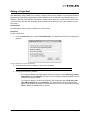
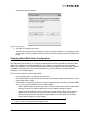
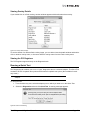
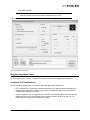
Uninstalling HBAnyware Web Launch Only
To uninstall HBAnyware Web Launch, but leave the HBAnyware utility installed:
In Windows:
1. Select Start> Programs>Emulex>HBAnyware WebLaunch Uninstall. The following screen
appears:
Figure 1: HBAnyware Web Launch, Uninstall screen
2. HBAnyware Web Launch is removed. Press any key to continue.
In Solaris SFS and Linux:
1. Log on as ‘root’.
Note: If you installed HBAnyware with Web Launch, you must uninstall it before uninstalling
the HBAnyware utility.
2. Execute the uninstallation script.
•
Solaris SFS:
/opt/HBAnyware/wsuninstall
The HBAnyware Utility User Manual
Page 13
•
Linux:
/usr/sbin/hbanyware/wsuninstall
This script stops the HBAnyware Web Launch Service daemons (if they are running) and removes all
Web Launch related files from the host.
Uninstalling the HBAnyware Utility
To uninstall the HBAnyware utility and HBAnyware Web Launch:
In Windows:
1. Select Start>Settings>Control Panel. The Add/Remove Programs window appears. Select the
Install/Uninstall tab.
2. Select Emulex HBAnyware and click Remove. Click Yes. The utilities are removed from the
system.
3. Select Emulex Common SAN Management and click Remove. Click Yes. The Emulex Common
SAN Management components are removed from the system.
4. Click Finish. Uninstallation is complete.
In Solaris SFS:
1. Log on as ‘root’.
2. Type:
pkgrm HBAnyware
In Linux:
1. Log in as ‘root’.
2. Obtain the current core kit RPM package name using the query:
rpm -qa | grep elxlinux
3. Erase the core kit package returned in step 1 using RPM erase:
(rpm -e xxxx) command
In VMware ESX Server (uninstalls the HBAnyware Agent):
1. Log in as ‘root’.
2. Type:
rpm -qa | grep elx
3. Locate the elxvmwarecorekit-<kit version>.rpm file. The .rpm contents are installed in
/usr/sbin/hbanyware. The hbacmd utility is also located in this directory.
4. Type:
rpm -e elxvmwarecorekit-<kit version>
The HBAnyware Utility User Manual
Page 14
Starting the HBAnyware Utility
To start the HBAnyware utility:
In Windows:
On the Windows desktop, select Start>All Programs>Emulex>HBAnyware.
In Solaris SFS and Linux:
1. Log on as ‘root’.
2. Run the script to start the HBAnyware utility.
•
On Solaris SFS:
•
/opt/HBAnyware/hbanyware
On Linux:
/usr/sbin/hbanyware/hbanyware
Starting HBAnyware with Web Launch
After the HBAnyware Web Launch software is installed and the Web Launch server is initialized, you can
launch the HBAnyware utility directly with your Web browser.
Note: Only the HBAnyware Web Launch GUI is exported to the requesting client. All
adapter discovery and remote management operations are performed by resources
running on the remote host that served up the GUI component. Therefore, the SAN
view displayed by the GUI is not from the client running the GUI, but rather from the
host from which this GUI was retrieved.
To launch the HBAnyware utility with your Web browser:
1. Open your Web browser. Linux and Solaris users must log on as ‘root’.
2. Enter the URL of an HBAnyware.jnlp file. Make sure that the URL specifies a remote server
which has the HBAnyware Web Launch software installed and running.
http://IP_ADDR:PORT_NUM/hbanyware.jnlp
where IP_ADDR is the IP address of the host on which you installed the HBAnyware Web
Launch Service, and PORT_NUM is the TCP port number of the listening hosts' Web server.
The standard HBAnyware user interface is displayed.
Managing Files when Running HBAnyware with Web Launch
When running HBAnyware with Web Launch, all files (log files, driver parameter files, firmware files,
etc.) are located on the browser launch host, which is not necessarily the same as the remote host that
is specified in the Web launch address.
The HBAnyware Utility User Manual
Page 15
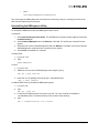
Using HBAnyware
Note: To properly view the HBAnyware utility, ensure your system meets the following display
requirements:
For Windows systems, the display resolution must be set to 800 by 600 or better.
For Linux and Solaris systems, the display resolution must be set to 1024 by 768 or better.
The display must run in 256-color mode or higher. HBAnyware icons use 256 colors. If the
display is set for 16 color mode, HBAnyware icons are not displayed.
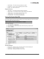
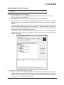
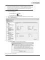
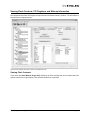
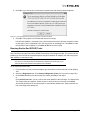
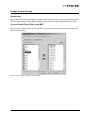
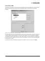
The HBAnyware Utility Window Element Definitions
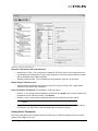
The HBAnyware utility window contains five basic components: the menu bar, the toolbar, the discoverytree, the property tabs and the status bar.
Figure 2: HBAnyware Utility window
Note: The element you select in the discovery-tree determines whether a menu item or
toolbar icon is active. For example, if you select the local host or other system host,
the Reset Adapter item on the Adapter menu is unavailable. The Reset Adapter
toolbar button is unavailable as well.
Note: Screenshots in this manual are for illustrative purposes only. Your system information
can vary.
Note: The features displayed by your local HBAnyware interface will match those of the
remote server. When accessing a remote server running an older version of the
HBAnyware utility, features that are not supported by the server’s older version of the
HBAnyware utility are unavailable.
The HBAnyware Utility User Manual
Page 16
Note: In some instances, the type of information displayed and available functionality is
determined by the operating system in use.
The Menu Bar
The menu bar contains commands that enable you to perform a variety of tasks such as exiting the
HBAnyware utility, resetting adapters and sorting items in the discovery-tree view. Many of the menu bar
commands are also available from the toolbar.
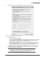
The Toolbar
The toolbar contains buttons that enable you to refresh the discovery-tree, reset the selected adapter
and choose how you want to view discovered SAN elements in the discovery-tree. Many of the toolbar
functions are also available from the menu bar.
Figure 3: Toolbar
The toolbar is visible by default. Use the Toolbar item in the View menu to hide the toolbar. If the item is
checked, the toolbar is visible.
The Toolbar Buttons
The toolbar buttons perform the following tasks:
Discovery Refresh button
• Refreshes the discovery cycle. A discovery refresh finds any new targets or virtual ports
that were added to the SAN and removes any targets or virtual ports that were removed.
Reset button
• Resets the selected adapter.
The View Buttons on the Toolbar
The View buttons on the toolbar enable you to view SAN elements from the host, fabric, virtual ports, or
by local or remote adapter perspective. By default, both local and remote adapters are displayed in
Host view. The HBAnyware utility displays elements in ascending order.
Host View button (default)
• Displays the host system.
Note: You cannot change host names using the HBAnyware utility; names must be changed
locally on that system.
•
•
•
•
•
•
Within each host system, displays the installed adapters.
Displays adapter ports and the port numbers if available.
If multiple adapters have the same model number, displays adapters by the WWNN.
If targets are present, displays the WWPN. Multiple adapters can refer to the same target.
If LUNs are present, displays the LUN number.
COMSTAR ports are located on the same level in the discovery-tree as initiator ports,
meaning that they branch out from adapters. Unlike initiator ports, however, targets do not
branch out from COMSTAR ports.
The HBAnyware Utility User Manual
Page 17
Fabric View button
• Displays the fabrics in the SAN with their fabric IDs.
• Displays the ports under each switch.
• If targets are present, displays each WWPN. Multiple adapters can refer to the same
target.
• If LUNs are present, displays each LUN number.
• If the fabric ID is all zeros, no fabric is attached.
Virtual Ports View button
• Displays virtual ports in the SAN.
Note: The Emulex emlxs driver for Solaris does not support COMSTAR running over virtual
ports, so the Virtual Ports view only displays initiator ports.
Local HBAs Only button
• Displays only local adapters.
Help button
• Displays the HBAnyware utility’s on-line help.
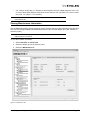
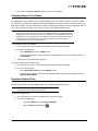
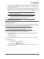
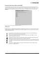
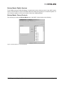
The Discovery-Tree
The discovery-tree (left pane) has icons that represent discovered hosts, adapters, ports, virtual ports,
fabrics, targets and LUNs.
Figure 4: Discovery-tree
The HBAnyware Utility User Manual
Page 18
Discovery-Tree Icons
Discovery-tree icons represent the following:
The local host.
Other hosts connected to the system.
A green adapter icon with black descriptive text represents an online adapter. Blue text
represents an adapter port that had previously been discovered, but currently is not being
seen by the discovery engine (service). The adapter will be removed from the discoverytree if it still is not seen after the undiscovered adapter expiration time (default is 1800
seconds, or 30 minutes). If the adapter is discovered again before the expiration time, it will
revert back to normal black text. See “Configuring Discovery, CIM Credentials and TCP/IP
Settings” on page 29 for more information about discovery settings.
A gray adapter icon indicates all ports for that adapter are no longer being discovered.
A red icon indicates all ports for the adapter are offline (link down). Several situations could
cause the adapter to be offline or inaccessible:
• The adapter on a local host is not connected to the network, but is available for local
access.
• The adapter on a local host is malfunctioning and inaccessible to the local host and the
network.
• The adapter on a local host is busy performing a local download and is temporarily
inaccessible to the local host and the network.
The port icon represents adapter ports. Newer adapters also display the port number.
A port icon with a red X indicates the port is down. If all discovered ports are down, the
adapter icon changes to red.
A gray port icon indicates that port is undiscovered. If all the ports are undiscovered, the
adapter icon changes to gray.
Note: Multiport adapters are represented in the discovery-tree with separate port icons for
each port. Older multiport adapter models (for example. LP8000DC, LP9402DC or
LP9002DC) are represented by separate adapter icons.
The Virtual Port icon represents virtual ports.
The Target icon represents connections to individual storage devices.
The COMSTAR icon represents COMSTAR ports. COMSTAR ports are unique in that a
single port can be shown simultaneously as both a manageable adapter port and a regular
target. When a COMSTAR port is seen as a target, it displays the Target discovery-tree icon
and Target dialog box information.
A COMSTAR icon with a red X indicates the port is down.
The LUN icon represents connections to individual disk LUNs.
The Tape LUN icon represents LUNs that are tape devices.
The Target Controller LUN icon represents LUNs that are storage controllers.
The HBAnyware Utility User Manual
Page 19
The Switch icon represents connections to the switch.
Expanding or Collapsing the Discovery-Tree View
You can also use the Expand/Collapse feature on the View menu to change the way discovered
elements are displayed. By selecting one of the four levels the discovery-tree is expanded or collapsed
to that level. You can choose Hosts/Fabrics (depending on the view) HBAs, Ports and Targets.
The Property Tabs
The property tabs display configuration, statistical and status information for network elements. The set
of available tabs is context-sensitive, depending on the type of network element or adapter port currently
selected in the discovery-tree.
The Status Bar
The status bar is located near the bottom of the HBAnyware utility window. The status bar displays
messages about certain HBAnyware utility functions, such as “Discovery in progress”.
The status bar is visible by default. Use the Status Bar item in the View menu to hide the status bar. If
checked, the status bar is visible.
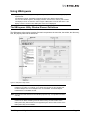
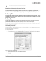
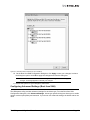
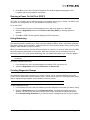
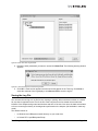
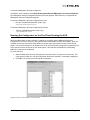
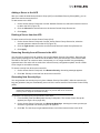
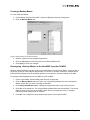
Customizing Tab Views
Using the Customize Tab Views dialog box you can choose whether or not to display certain property
tabs. By default, all tabs are displayed.
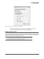
To customize tab views:
1. From the View menu, select Customize Tabs. The Customize Tab Views dialog box appears.
Figure 5: Customize Tab Views dialog box
2. Check tabs to display them. Clear tabs to hide them.
3. Click OK.
The HBAnyware Utility User Manual
Page 20
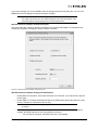
Changing Management and Read-Only Mode
During installation, you selected both a management and a read-only mode. If you also chose to enable
modification of these settings after installation, then you can choose three types of host/adapter
management:
•
Strictly Local Management - This setting only allows management of adapters on this host.
Management of HBAs on this host from other hosts is not allowed.
•
Local Management Plus - This setting only allows management of adapters on this host, but
management of HBAs on this host from another host is possible.
•
Full Management - This setting enables you to manage adapters on this host and other hosts
that allow it.
If Management Mode was enabled during installation, you can also set read-only mode.
•
Read-only mode - This setting prevents performance of certain operations such as resetting
adapters, updating the adapter or Converged Enhanced Ethernet (CEE) firmware image and
changing adapter driver properties and bindings. Dialog box buttons and menus that pertain to
these tasks are completely hidden or inactive.
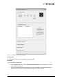
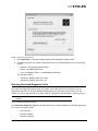
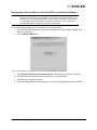
To change management/read-only mode:
Note: You must restart the HBAnyware utility to see the new management mode.
In Windows:
1. From the File menu, select Management Mode. The Management Mode dialog box appears.
Figure 6: Management Mode dialog box
2. Choose the management type and read-only mode you want.
3. Click OK.
In Solaris SFS:
1. Run the following script:
/opt/HBAnyware/set_operating_mode
The HBAnyware Utility User Manual
Page 21
2. Choose the management type and read-only mode you want.
In Linux:
1. Stop the HBAnyware utility.
2. Run the following script:
/usr/sbin/hbanyware/set_operating_mode
3. Choose the management type and read-only mode you want. Enter <y> 'for yes to allow the
user to perform these operations, enter <n> for no if read-only mode is desired.
The HBAnyware Utility User Manual
Page 22
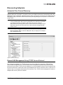
Discovering Adapters
Automatic Fibre Channel Discovery
Adapters that have a physical FC connection to the same SAN are discovered automatically when the
HBAnyware utility is launched. Adapters that don't have a physical FC connection to the SAN where the
HBAnyware utility is launched can be discovered by sending management requests to a remote host
using TCP/IP.
Note: The HBAnyware utility can only discover and manage remote adapters on hosts
running the HBAnyware utility’s remote management server. Remote FC capabilities
of the HBAnyware utility are subject to fabric zoning and may be reduced if
HBAnyware security is being used. Hosts you want to discover and manage using the
HBAnyware utility must be in the same zone or discovered and managed through
TCP/IP access.
Note: After adding an adapter to a running system (commonly called a hot plug), click
Discovery Refresh ( ) or restart the HBAnyware utility to display the new adapter
port in the discovery-tree.
Figure 7: Discovery Information
Remote SAN Management Using TCP/IP Access Protocol
You can discover adapters on TCP/IP hosts and on hosts configured to support the CIM interface.
Remote SAN management over TCP/IP sends remote management requests using TCP/IP access
protocol to remote hosts. TCP/IP access enables you to access adapters via their host IP-address or by
the name of the host on which they reside. Since adapters can exist on a host but not be a part of a FC
network, they do not appear during normal FC discovery. Thus, TCP/IP access enlarges the number of
adapters that can be queried or modified.
The HBAnyware Utility User Manual
Page 23
Note: In Windows, if you are running a firewall you may need to add the HBAnyware remote
server to the firewall’s exception list. This remote server’s path is:
\Program Files\Emulex\Util\Common\rmserver.exe
On 64-bit hosts the path is
\Program Files (x86)\Emulex\Util\Common\rmserver.exe
The principle differences between FC and TCP/IP access are:
•
A TCP/IP host with or without an adapter installed does not need to connect to a fabric to
manage other hosts.
•
A TCP/IP management host can manage all of the adapters in a remote host, not just the ones
connected to the same fabric. FC can only manage adapters connected to the same fabric.
•
You can manage many more hosts since TCP/IP access is not constrained by the boundaries of
a fabric or zoning.
•
True board status (e.g. link down) is available since the FC path is not necessary to send a
status request to the remote host.
•
Adapter security in a TCP/IP environment is much more important since many more hosts are
available for management and TCP/IP access is not affected by fabrics or zoning.
•
Discovery of hosts in a TCP/IP environment is not automatic as FC discovery is. You must add
the hosts to be managed.
The Hosts File
The TCP/IP discovery portion of the HBAnyware discovery server relies on a file called the hosts file.
This plain text file contains a list of hosts the utility will attempt to discover. The discovery server does
not attempt to discover hosts over TCP/IP through any other mechanisms (e.g. ping sweeps,
broadcasts, etc.).
The hosts file is automatically created or modified when you perform any of the following operations:
•
Add a single host from the Add Remote Host window. If the host is discovered, the HBAnyware
utility adds its IP address and name to the host file.
•
Scan a range or ranges of IP addresses for hosts that can be managed. This is performed in the
Add Remote Hosts window. For each discovered host, the HBAnyware utility adds the IP
address and name to the host file.
•
Remove a host from the host file from the Remove Remote Hosts window. For each removed
host, the HBAnyware utility removes that IP address and name from the host file.
Manually Editing the Hosts File
You can open the hosts file with any text editor, modify the contents and save the file. The name of the
host file is “hbahosts.lst”. Once the file is modified and saved, the updated file is used after the next
TCP/IP discovery cycle is complete. If the discovery server is running, it does not need to be restarted.
To manually edit the hosts file:
1. Locate and open the hosts file.
Windows: The file is located on the system drive in the directory "\Program Files\Emulex\Util" for
32-bit machines or "\Program Files (x86)\Emulex\Util" for 64-bit machines.
Solaris: The file is located in the directory "/opt/HBAnyware".
Linux: The file is located in the directory "/usr/sbin/hbanyware".
The HBAnyware Utility User Manual
Page 24
2. Edit the file. Guidelines for editing the file are as follows:
•
Each line of the file starts with an IP address. Following the IP address can be any number
of tabs or spaces. This is followed by a “#” character, zero or more tabs or spaces and the
name of the host for that IP address. The host name is not required for discovery. Its
purpose is to make the file more readable and is used by the HBAnyware utility to display
the host name in the Remove Remote Hosts window when the host is not discovered.
However, the discovery server only needs the IP address to discover the host.
•
Each line in the file can be up to 1023 characters, although this is longer than is needed for
a host IP address and host name. A line longer than this is truncated, possibly causing
discovery to not discover some of the hosts.
•
Blank lines are ignored.
3. Save the file.
Copying the File
A hosts file on one host can be copied and used on another host. This is useful if there are multiple hosts
on the same network running the HBAnyware utility. Once the remote hosts are added to the hosts file
on one host, that hosts file can be copied to other hosts so the process to create the hosts file does not
need to be repeated.
Note: Due to the line terminator differences between Windows and Solaris or Linux hosts,
the files cannot be shared between Windows hosts and Solaris or Linux hosts.
The HBAnyware Utility User Manual
Page 25
Adding a Single Host
The HBAnyware utility enables you to specify a single TCP/IP host to manage. You can add a Resource
Management Application Programming Interface (RMAPI) host or CIM host using the host name or IP
address. If the host is successfully discovered it is added to the hosts file. If it has not been discovered
over FC already, the host and its adapter ports are added to the discovery-tree. (Not available in readonly mode.)
Prerequisites
The HBAnyware utility must be installed on the remote host.
Procedure
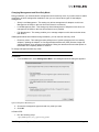
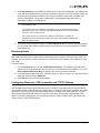
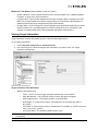
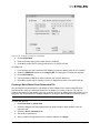
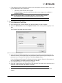
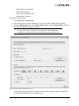
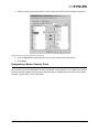
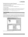
To add a single host:
1. From the Discovery menu, select TCP/IP>Add Host. The Add Remote TCP/IP Host dialog box
appears.
Figure 8: Add Remote TCP/IP Host dialog box
2. Enter the name or the IP address of the host to be added.
Note: Entering the IP address to identify the host avoids possible name resolution issues.
3. Configure the discovery method:
•
If you want to add the host using default discovery methods, check Add using default
credentials and click Add Host. You will receive a message indicating whether the new
host was successfully added.
•
If you want to add the new host using specific CIM credentials, check Add using specific CIM credentials and click Add Host. The Add Remote TCP/IP Host dialog box
appears with default CIM settings. CIM credentials are most often used when managing
VMware ESX 3i or VMware ESX 4i servers.
The HBAnyware Utility User Manual
Page 26
Figure 9: Add Remote TCP/IP Host dialog box with CIM Credentials
a. Edit the default CIM settings if necessary and click Add Host. You will receive a
message indicating whether the new host was successfully added.
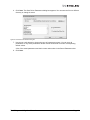
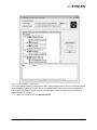
Adding a Range of Hosts
Find the TCP/IP-accessed manageable hosts by searching a range of IP addresses. The Add Range of
TCP/IP Hosts dialog box enables you to build the initial list of TCP/IP accessed manageable hosts. (Not
available in read-only mode or on Windows XP or Vista.)
Note: The ranges of IP addresses are only scanned each time you open the Add Remote
TCP/IP Hosts dialog box and click Start Discovery. The ranges are NOT automatically
scanned by the discovery server during its discovery cycles.
The HBAnyware Utility User Manual
Page 27
Figure 10: Add Range of TCP/IP Hosts dialog box
Prerequisites
The HBAnyware utility must be installed on all remote hosts.
Procedure
To add a range of remote hosts:
1. From the Discovery menu, select TCP/IP>Add Remote Hosts. The Add Range of TCP/IP
Hosts dialog box appears.
2. Enter the complete start and end address range and click Add. The added address range
appears in the dialog box. Add any additional ranges you want to search.
The HBAnyware Utility User Manual
Page 28
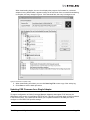
3. Click Start Discovery. If an address is determined to be remotely manageable, it is added to the
list of addresses that the discovery server will attempt to discover. The utility creates a host file if
necessary, and checks each address in the range to determine if the host is available and
remotely manageable. The number of addresses (of manageable hosts) discovered is
periodically updated on the dialog box.
Note: The number of addresses does not correspond directly to the number of hosts added
to the discovery-tree.
For example, some of the addresses discovered may be for hosts that have already
been discovered over FC. However, new adapters can be discovered on those hosts
that were not discovered over FC.
Also, a host can have more than one IP address assigned to it. If multiple IP
addresses for a host are discovered during the search, the host will be added to the
discovery tree only once.
4. You can save the IP address ranges. Click Save Ranges to File to save the specified range(s)
to a file so that these address ranges appear the next time you use the Add Range of TCP/IP
Hosts dialog box.
Removing Hosts
Removing hosts that can no longer be discovered improves the operation of the discovery server. For
example, you may want to remove a host when it is removed from the network. (Not available in readonly mode.)
To remove hosts:
1. From the Discovery menu, select TCP/IP>Remove Host(s). The Remove Hosts dialog box
shows a list of discovered hosts. Any host that is not currently discovered appears in red. Click
Show Undiscovered Hosts Only to display only currently undiscovered hosts.
2. From the Remove Hosts dialog box, select the hosts you want to remove. You can select all the
displayed hosts by clicking Select All.
3. Click Remove to remove the selected hosts.
Configuring Discovery, CIM Credentials and TCP/IP Settings
Use the HBAnyware Discovery Settings dialog box to configure several discovery server parameters.
You can define when to start the discovery server, when to refresh FC and TCP/IP accessed discoveries
and when to remove previously discovered HBAs that are no longer being discovered. You can also
define default CIM credentials such as the protocol, user name, port number, password and name
space. For TCP/IP management, you can specify an IP port number, change an IP port number and
enable a port for TCP/IP management.
The HBAnyware Utility User Manual
Page 29
Figure 11: HBAnyware Discovery Settings dialog box
To configure discovery settings:
1. From the Discovery menu, select Modify Settings. The HBAnyware Discovery Settings dialog
box appears.
2. Define the discovery properties you want.
3. If TCP/IP Management is enabled, the Enable TCP/IP Management checkbox is selected and
the current port number is displayed in the Port Number field. If desired, enter a different port
number (between 1024 and 65535). Click Defaults to select the Enable TCP/IP Management
checkbox (if unchecked) and set the port number to 23333.
If the port number or the Enable TCP/IP Management checkbox is changed, a set of warning
messages may appear before changes are made. Click Yes on the warning message to continue with the change.
Caution: The IP port number must be the same for all hosts that are to be managed.
Setting an IP port number for one host to a different value than the other hosts
will make the host unable to manage other hosts over TCP/IP, as well as
make the host unmanageable over TCP/IP from other hosts.
4. If the IP port number is changed, the utility restarts the HBAnyware discovery server and
management agent to use the new settings. If the servers cannot be stopped and restarted, you
are prompted to reboot the host for the new TCP/IP management settings to take effect.
5. If you want, edit the CIM credentials.
The HBAnyware Utility User Manual
Page 30
6. Click OK to apply your changes. Click Defaults to return the discovery properties to their default
settings.
Viewing Discovery Information
The Discovery Information page contains a general summary of the discovered elements. The Host,
Fabric or Virtual Port icon, depending upon which view you select, is the root of the discovery-tree, but it
does not represent a specific network element. Expanding it reveals all hosts, LUNs, targets, adapters
ports and virtual ports that are visible on the SAN.
To view the discovery information:
1. Click the Hosts, Fabrics or Virtual Port icon at the root of the discovery-tree. Discovered SAN
elements appear in the discovery-tree.
2. Select an element from the discovery-tree to learn more about it.
Figure 12: Discovery Information (Virtual Port view selected)
Discovery Information Field Definitions
•
Number of Hosts - The total number of discovered host computers. This includes servers,
workstations, personal computers, multiprocessor systems and clustered computer complexes.
•
Number of Fabrics - The total number of discovered fabrics.
•
Number of Adapters - The total number of discovered adapters.
•
Number of Adapter Ports - The number of discovered adapter ports on this host that can be
managed by this host.
•
Number of Target Ports - The total number of unique discovered targets on the SAN. In the
discovery-tree, the same target can appear under more than one adapter.
The HBAnyware Utility User Manual
Page 31
•
Number of Virtual Ports - The number of discovered virtual ports on this host that can be
managed by this host. (Only displayed if the Virtual Ports element is selected in the discoverytree.)
Viewing Host Information
There are two tabs that show host information: the Host Information tab and the Host Driver Parameters
tab. The Host Information tab is read-only. The Host Driver Parameters tab enables you to view and
define adapter driver settings for a specific host. See “The Host Driver Parameters Tab” on page 50 for
more information about the Host Driver Parameters tab.
To view the Host Information and Host Driver Parameters tabs:
1. Do one of the following:
•
From View menu, click Hosts.
•
From the toolbar, click
Host View.
2. Select a host in the discovery-tree.
3. Select the Host Information tab or the Host Driver Parameters tab.
The Host Information tab displays information for the selected host including the number of adapters
installed in the selected host, the number of fabrics to which it is connected and so on.
Figure 13: Host Information tab
Host Information Field Definitions
•
Number of Adapters - The number of adapters installed in the host.
•
Number of Adapter Ports - The number of discovered adapter ports on this host that can be
managed by this host.
•
Number of VPorts - The number of discovered virtual ports that can be managed by this host.
(Not supported on VMware ESX servers being managed through the CIM interface.)
•
Number of Fabrics - The number of fabrics to which this host is attached. (Not supported on
VMware ESX servers being managed through the CIM interface.)
•
Number of Virtual Machines - The number of virtual machines that can be seen by this host. (Not
supported on VMware ESX servers being managed through the CIM interface.)
The HBAnyware Utility User Manual
Page 32
•
Number of Target Ports - The number of storage devices seen by the host.
•
Remote Manager Server Version - The version of the HBAnyware utility server that is running on
the host. If different versions of the HBAnyware utility are installed on different hosts in the SAN,
those differences appear in this field.
•
Operating System - The operating system and version installed on the selected host.
•
Management IP Address - If the host is discovered with FC, the Management IP Address field
displays “Host discovered over Fibre Channel”. If the host has been added with TCP/IP access,
the Management IP Address field displays the host's IP address, for example, 138.239.82.131.
"Local Host" is displayed if you selected the host you are actually launching from.
•
CIM Provider Version - If the host is being managed using the CIM interface, the "CIM Provider
Version" field will display the version of the Emulex CIM provider that is running on the remotely
managed system.
Note: The CIM Provider Version field only appears if the host is managed through the CIM
interface.
Viewing Adapter Information
The Adapter Information tab contains general attributes associated with the selected adapter.
Note: Not all information is displayed on systems using CIM provider v1.2.1 on ESX 3i.
To view general adapter information:
1. Select Host View or Virtual Ports View.
2. Select an adapter in the discovery-tree.
Figure 14: Adapter Information tab
Adapter Information Field Definitions
•
Model - The complete model name of the adapter.
•
Serial Number - The manufacturer's serial number for the selected adapter.
•
Hardware Version - The board Joint Electron Devices Engineering Council identification (JEDEC
ID) ID version for the selected adapter.
•
Device ID - The default device ID for the selected adapter. (Not supported on VMware ESX
servers being managed through the CIM interface.)
The HBAnyware Utility User Manual
Page 33
•
Adapter Temperature - If the adapter's temperature is not available, “Not Supported” is
displayed. (Not supported on VMware ESX servers being managed through the CIM interface.)
If supported by the adapter, this field displays the adapter's temperature and one of the following
temperature-related status messages:
•
Normal: The adapter’s temperature is within normal operational range.
•
Exceeded operational range - Critical: The adapter’s temperature is beyond normal
operational range. If the temperature continues to increase, the adapter shuts down. You
must determine the cause of the temperature problem and fix it immediately. Check for
system cooling issues. Common causes of system cooling issues include clogged air filters,
inoperable fans and air conditioning problems that cause high ambient air temperatures.
•
Exceeded operational range - Adapter stopped: The temperature has reached critical limit,
forcing the adapter to shut down. You must determine the cause of the temperature problem
and fix it before resuming operation. Check for system cooling issues. Common causes of
system cooling issues include clogged air filters, inoperable fans and air conditioning
problems that cause high ambient air temperatures.
After the system overheating issue is resolved and the adapter has cooled down, reboot the
system or, if the system supports hot swapping, cycle the power of the adapter slot.
Viewing Port Information
The Port Information tab contains detailed information associated with the selected adapter port.
Note: Not all information is displayed on systems using CIM provider v1.2.1 on ESX 3i.
To view port information:
1. Select Host View or Fabric View.
2. Select an adapter port in the discovery-tree.
3. Select the Port Information tab.
The HBAnyware Utility User Manual
Page 34
Figure 15: Port Information tab
Port Attributes Area Field Definitions
•
Port WWN - The Port World Wide Name of the adapter.
•
Node WWN - The Node World Wide Name of the selected adapter.
•
Fabric Name or Host Name - The Fabric Name field is displayed in Host view. This is a 64-bit
worldwide unique identifier assigned to the fabric. The Host Name is displayed in Fabric view.
The host name is the name of the host containing the adapter. (Not supported on VMware ESX
servers being managed through the CIM interface.)
•
Boot Version - The version of boot code installed on the selected adapter port. If the boot code is
disabled, the field displays ”Disabled”.
•
Port FC ID - The Fibre Channel ID for the selected adapter port.
•
Driver Version - The version of the driver installed for the adapter.
•
Driver Name - The executable file image name for the driver as it appears in the Emulex driver
download package.
•
Firmware Version - The version of Emulex firmware currently active on the adapter port.
•
Discovered Ports - The number of mapped and unmapped ports found during discovery by the
Emulex adapter driver. The mapped ports are targets and the unmapped ports are non-targets
such as switches or adapters.
•
Port Type - The current operational mode of the selected adapter’s port.
•
OS Device Name - The platform-specific name by which the selected adapters is known to the
operating system. (Not supported on VMware ESX servers being managed through the CIM
interface.)
The HBAnyware Utility User Manual
Page 35
•
Symbolic Node Name - The FC name used to register the driver with the name server.
•
Supported Class of Service - A frame delivery scheme exhibiting a set of delivery characteristics
and attributes. There are three classes of service.
•
•
Class-1 provides a dedicated connection between a pair of ports with confirmed delivery or
notification of non-delivery.
•
Class-2 provides a frame switched service with confirmed delivery or notification of nondelivery.
•
Class-3 provides a frame switched service similar to Class-2 but without notification of frame
delivery or non-delivery.
Supported FC4 Types - A 256-bit (8-word) map of the FC-4 protocol types supported by the port
containing the selected adapter.
Port Status Area Field Definitions
•
Link Status - The status of the link on the selected adapter port.
•
Link Speed - The current link speed of the selected adapter port.
Loop Map Table Definitions
•
The loop map shows the different ports present in the loop, and is present only if the port
(adapter) is operating in loop mode. The simplest example would be to connect a JBOD directly
to an adapter. When this is done, the port type is a private loop, and the loop map has an entry
for the adapter, and one entry for each of the disks in the JBOD. (Not supported on VMware ESX
servers being managed through the CIM interface. Not supported for COMSTAR ports.)
The HBAnyware Utility User Manual
Page 36
Viewing Port Statistics
The Statistics tab provides cumulative totals for various error events and statistics on the port. Some
statistics are cleared when the adapter is reset.
Note: Not all information is displayed on systems using CIM provider v1.2.1 on ESX 3i.
To view port statistics:
1. Select Host View or Fabric View.
2. Select an adapter port in the discovery-tree.
3. Click the Statistics tab.
Figure 16: Statistics tab
Port Statistics Field Definitions
•
Tx Frames - FC frames transmitted by this adapter port.
•
Tx Words - FC words transmitted by this adapter port.
•
Tx KB Count - FC kilobytes transmitted by this adapter port.
•
Tx Sequences - FC sequences transmitted by this adapter port.
•
LIP count - The number of loop initialization primitive (LIP) events that have occurred for the
port. This field is not supported if the topology is not arbitrated loop. Loop initialization consists
of the following:
•
Temporarily suspending loop operations.
The HBAnyware Utility User Manual
Page 37
•
Determining whether loop capable ports are connected to the loop.
•
Assigning AL_PA IDs.
•
Providing notification of configuration changes and loop failures.
•
Placing loop ports in the monitoring state.
•
Error Frames - The number of frames received with cyclic redundancy check (CRC) errors.
•
Link Failures - The number of times the link has failed. A link failure is a possible cause of a
timeout.
•
Loss of Signal - The number of times the signal was lost.
•
Invalid Tx Words - The total number of invalid words transmitted by this adapter port.
•
Ex Count Orig - The number of FC exchanges originating on this port. (Not supported on
VMware ESX servers being managed through the CIM interface.)
•
Active XRIs - The number of active exchange resource indicators. (Not supported on VMware
based ESX platforms using the CIM interface.)
•
Received P_BSY - The number of FC port-busy link response frames received.
•
Link Transitions - The number of times the SLI port sent a link attention condition.
•
Elastic Buf Overruns - The number of times the link interface has had its elastic buffer overrun.
•
Rx Frames - The number of FC frames received by this adapter port.
•
Rx Words - The number of FC words received by this adapter port.
•
Rx KB Count - The received kilobyte count by this adapter port.
•
Rx Sequences - The number of FC sequences received by this adapter port. (Not supported on
VMware ESX servers being managed through the CIM interface.)
•
NOS count - The number of NOS events that have occurred on the switched fabric. Note: This
statistic is currently not supported for the SCSIport Miniport and Storport Miniport drivers, nor is
it supported for arbitrated loop.
•
Dumped Frames - The number of frames that were lost due to a lack of host buffers available.
Note: This statistic is not currently supported for the SCSIport Miniport driver, the Storport
Miniport driver or the driver for Solaris.
•
Loss of Sync - The number of times loss of synchronization has occurred.
•
Prim Seq Prot Errs - The primitive sequence protocol error count. This counter is incremented
whenever there is any type of protocol error.
•
Invalid CRCs - The number of frames received that contain CRC failures.
•
Ex Count Resp - The number of FC exchange responses made by this port. (Not supported on
VMware ESX servers being managed through the CIM interface.)
•
Active RPIs - The number of remote port indicators. (Not supported on VMware ESX servers
being managed through the CIM interface.)
•
Receive F_BSY - The number of FC port-busy link response frames received.
•
Primitive Seq Timeouts - The number of times a primitive sequence event timed out. (Not
supported on VMware ESX servers being managed through the CIM interface.)
•
Arbitration Timeouts - The number of times the arbitration loop has timed out. Large counts
could indicate a malfunction somewhere in the loop or heavy usage of the loop. (Not supported
on VMware ESX servers being managed through the CIM interface.)
If you selected a COMSTAR port, the following information is also displayed:
•
SCSI Write I/O Count - The number of SCSI Write I/O requests received.
•
SCSI Write KB Count - The total number of kilobytes written.
The HBAnyware Utility User Manual
Page 38
•
Total SCSI I/O Count - The number of SCSI I/O requests received.
•
No Receive Buffer Count - The number of SCSI I/O requests that were dropped.
•
Queue Depth Overflow Count - The number of SCSI I/O requests received after a QFULL
condition.
•
Dropped SCSI I/O Count - The number of dropped SCSI I/O operations.
•
Aborted SCSI I/O Count - The number of aborted SCSI I/O operations.
•
Outstanding SCSI I/O Count - The number of SCSI I/O requests currently pending.
•
SCSI Read I/O Count - The number of SCSI Read I/O requests received.
•
SCSI Read KB Count - The total number of kilobytes read.
•
SCSI Status Errors - The number of SCSI status errors sent to the initiator.
•
SCSI Queue Full Errors - The number of QFULL errors sent to the initiator.
•
SCSI Sense Errors - The number of of times sense data was sent to the initiator.
•
SCSI Residual Over - The number of residual overruns returned to the initiator.
•
SCSI Residual Under - The number of residual underruns returned to the initiator.
Viewing Virtual Port Information
Use the Virtual Ports tab to view information about virtual ports and their associated targets and LUNs.
To view virtual port information:
1. Do one of the following:
•
From the View menu, select Virtual Ports.
•
From the toolbar, click
Virtual Ports View.
Figure 17: Virtual Ports Information
Virtual Port Information Field Definitions
•
Number of Hosts - The total number of hosts discovered in the SAN.
•
Number of Fabrics - The total number of fabrics discovered in the SAN.
•
Number of Adapters - The total number of adapters discovered in the SAN.
•
Number of Adapter Ports - The total number of adapter ports discovered in the SAN.
The HBAnyware Utility User Manual
Page 39
•
Number of Target Ports - The total number of target ports discovered in the SAN.
•
Number of Virtual Ports - The total number of virtual ports discovered in the SAN.
Viewing Fabric Information
The Discovery Information tab contains information about the selected fabric.
To view fabric discovery information:
1. Do one of the following:
•
From the View menu, select Fabric.
•
From the toolbar, click
Fabric View.
The Discovery Information tab shows information about the fabric.
Figure 18: Fabric Discovery Information
Discovery Information Field Definitions
•
Number of Hosts - The number of hosts discovered or seen by this host on the selected fabric.
•
Number of Fabrics - The number fabrics identified during discovery.
•
Number of Adapters - The number of adapters discovered by this host on the selected fabric.
•
Number of Adapter Ports - The number of discovered adapter ports on this host that can be
managed by this host.
•
Number of Target Ports - The number of storage devices seen by this host on the selected
fabric.
The HBAnyware Utility User Manual
Page 40
Viewing Transceiver Information
The Transceiver Data tab enables you to view transceiver information such as vendor name, serial
number, part number and so on. If the adapter does not support this feature the fields display N/A.
Note: Not supported on systems using CIM provider v1.2.1 on ESX 3i.
To view transceiver information:
1. Select Host View or Fabric View.
2. In the discovery tree, select the port whose transceiver information you want to view.
3. Select the Transceiver Data tab.
Figure 19: Transceiver Data tab
Transceiver Information Field Definitions
Module Attributes Area
•
Vendor - The name of the vendor.
•
Identifier/Type - The identifier value that specifies the physical device described by the serial
information.
•
Ext. Identifier - Displays additional information about the transceiver.
•
Connector - The external optical or electrical cable connector provided as the media interface.
•
Wavelength - The nominal transmitter output wavelength at room temperature.
•
OUI - Displays the vendor Organizationally Unique Identifier. It is also known as the IEEE
Company Identifier for the vendor.
•
Date - The vendor’s date code in the MM/DD/YY format.
The HBAnyware Utility User Manual
Page 41
•
Serial Number - The serial number provided by the vendor.
•
Part Number - The part number provided by the SFP vendor.
•
Revision - The vendor revision level.
Diagnostic Data Area
•
Temperature - The internally measured module temperature.
•
Supply Voltage - The internally measured supply voltage in the transceiver.
•
TX Bias Current - The internally measured TX bias current.
•
TX Output Power - The measured TX output power
•
RX Output Power - The measured RX output power.
Viewing Vital Product Data (VPD)
The VPD tab displays vital product data (if available) for the selected adapter port such as the product
name, part number, serial number and so on.
Note: Not supported on systems using CIM provider v1.2.1 on ESX 3i.
To view VPD information:
1. Select Host View or Fabric View.
2. In the discovery tree, select the port whose VPD information you want to view.
3. Select the VPD tab.
Figure 20: VPD tab
VPD Table Definitions
•
Product Name - Displays product information about the selected adapter port.
•
Part Number - Displays the adapter's part number.
•
Serial Number - Displays the adapter's serial number.
The HBAnyware Utility User Manual
Page 42
•
VO - Vendor unique data. “V” indicates a vendor-specific field. An adapter may have none, one
or more of these fields defined. Valid values for this field are “VO” (the letter “O”, not the number
zero) and “Vx” (where “x” is a number).
Note: Some adapters may show additional VPD information such as EC (EC level) and MN
(manufacturer ID)
Viewing Maintenance Information
Use the Maintenance tab to view and change current firmware and boot code information. Use this tab to
also view and change WWPN and WWNN information for the selected adapter port. (Not available in
read-only mode.)
Note: Not all information is displayed on systems using CIM provider v1.2.1 on ESX 3i. and
CIM provider v2.0 on ESX 4i.
To view the firmware information:
1. Select Host View or Fabric View.
2. Select an adapter port in the discovery-tree.
3. Select the Maintenance tab.
Figure 21: Maintenance Tab
The HBAnyware Utility User Manual
Page 43
Firmware Field Definitions
Firmware Area
•
Current Version - The Emulex firmware version number for this model of adapter.
•
Initial Load - The firmware version stub responsible for installing SLI code into its proper
slot. (Not available on VMware ESX servers being managed through the CIM interface.)
•
SLI-2 Name - The name of the SLI-2 firmware overlay. (Not available on VMware ESX
servers being managed through the CIM interface.)
•
Kernel Version - The version of the firmware responsible for starting the driver. (Not
available on VMware ESX servers being managed through the CIM interface.)
•
Operational Name -The name of the operational firmware for the selected adapter. (Not
available on VMware ESX servers being managed through the CIM interface.)
•
SLI-1 Name - The name of the SLI-1 firmware overlay. (Not available on VMware ESX
servers being managed through the CIM interface.)
•
SLI-3 Name - The name of the SLI-3 firmware overlay. (Not available on VMware ESX
servers being managed through the CIM interface.)
•
Adapter Boot Version - Displays one of the following:
•
•
The selected adapter port's boot code version if boot code is present.
•
“Disabled” if the boot code is disabled.
•
“Not Present” if boot code is not loaded. If boot code is not loaded, the Enable Adapter
boot checkbox is not visible and you cannot configure the selected port to boot from
SAN.
Enable adapter boot checkbox - Check this box if you want the adapter to load and execute
boot code during system startup. Click Configure Boot to configure boot from SAN. (Not
available in read-only mode.) See “Configuring Boot from SAN” on page 89 for more
information.
Note: Enabling adapter boot only causes the adapter to load the boot code and execute it
during system startup. It does not mean that the adapter will boot from SAN. To boot
from SAN, the boot type must be enabled to boot from SAN. Do this in the Boot from
SAN configuration window for each boot type. In addition, the BIOS must be
configured to boot from SAN.
WWN Management Area
Note: Not supported on COMSTAR and VMware ESX servers being managed through the
CIM interface.
Current
•
WWPN - Displays the World Wide Port Name for the selected adapter port.
•
WWNN - Displays the World Wide Node Name for the selected adapter port.
Pending Changes
•
WWPN - Works in conjunction with the Change WWN button. Displays the World Wide Port
Name you assigned for the selected adapter port, but the system must be rebooted for these
changes to take effect and appear under the “Current” listing. See “Configuring Boot from SAN”
on page 89 for more information.
•
WWNN - Works in conjunction with the Change WWN button. Displays the World Wide Node
Name you assigned for the selected adapter port, but the system must be rebooted for these
changes to take effect and appear under the “Current” listing. See “Configuring Boot from SAN”
on page 89 for more information.
The HBAnyware Utility User Manual
Page 44
Maintenance Tab Buttons (Not available in read-only mode.)
•
Update Firmware - Click to update firmware on the selected adapter. See “Updating Adapter
Firmware” on page 74 for more information.
•
Configure Boot - Check Enable adapter boot and click Configure Boot to configure boot from
SAN. See “Configuring Boot from SAN” on page 89 for more information. (Not available on
VMware ESX servers being managed through the CIM interface.)
•
Change WWN - Click to change the selected adapter port's World Wide Node Name or World
Wide Port Name. See “Configuring Boot from SAN” on page 89 for more information. (Not
available on VMware ESX servers being managed through the CIM interface.)
Viewing Target Information
Target Information contains information specific to the selected storage device.
To view target information:
1. Select Host View, Fabric View or Virtual Port View.
2. In the discovery-tree, select the target whose information you want to view. The Target
Information tab appears.
Figure 22: Target Information tab
Target Information Field Definitions
•
Mapping Information Area
•
FC ID - The FC ID for the target; assigned automatically in the firmware.
•
SCSI Bus Number - The SCSI Bus number to which the target is mapped.
•
SCSI Target Number - The target's identifier on the SCSI Bus.
•
Node WWN - A unique 64-bit number, in hexadecimal, for the target (N_PORT or
NL_PORT).
•
Port WWN - A unique 64-bit number, in hexadecimal, for the fabric (F_PORT or Switched
Fabric Loop Port [FL_PORT]).
•
OS Device Name - The operating system device name.
Note: See “Masking and Unmasking LUNs (Windows)” on page 84 for more information on
LUN Masking.
The HBAnyware Utility User Manual
Page 45
Viewing LUN Information
The LUN Information tab contains information about the selected logical unit number (LUN).
Note: LUNs that are associated with a manageable COMSTAR port will not appear in the
discovery-tree and cannot be configured using the HBAnyware utility or HbaCmd. To
view the LUNs using the HBAnyware utility, you must view the COMSTAR port as a
target.
To view the LUN information:
1. Select Host View, Fabric View or Virtual Port View.
2. In the discovery-tree, select the LUN whose information you want to view. The LUN Information
tab appears.
Figure 23: LUN Information
LUN Information Field Definitions
Vendor Product Information Area
•
Vendor Name - The name of the vendor of the LUN.
•
Product ID - The vendor-specific ID for the LUN.
•
Revision - The vendor-specific revision number for the LUN.
Mapping Information Area
•
FCP LUN - The FC identifier used by the adapter to map to the SCSI OS LUN.
•
SCSI OS LUN - The SCSI identifier used by the OS to map to the specific LUN.
•
OS Device Name - The name assigned by the OS to the LUN.
The HBAnyware Utility User Manual
Page 46
LUN Capacity Area
Note: LUN capacity information is only provided when the LUN is a mass-storage (disk)
device. Other devices like tapes and scanners, etc. do not display capacity.
•
Capacity - The capacity of the LUN, in megabytes.
•
Block Size - The length of a logical unit block in bytes.
LUN Masking Area
•
Current Mask Status - Possible states are masked or unmasked.
Viewing Target Mapping (Windows and Solaris SFS)
The Target Mapping tab enables you to view current target mapping and to set up persistent binding.
Note: On Solaris SFS systems persistent binding is not supported.
Note: Target Mapping tab is not available on COMSTAR ports.
To view target mapping:
1. Select Host View or Fabric View.
2. In the discovery-tree, select the adapter port whose target mapping information you want to
view.
3. Select the Target Mapping tab.
Figure 24: Target Mapping tab
The HBAnyware Utility User Manual
Page 47
Target Mapping Field Definitions
Current Settings Area
•
Active Bind Type - WWPN, WWNN, or a destination identifier (D_ID).
•
Automapping - The current state of SCSI device automapping: enabled (default) or disabled.
•
Auto-Persistent Binding - The current state of the Auto-Persistent binding service. (Not available
on VMware ESX servers being managed through the CIM interface.)
Current Mappings Area
•
This table lists current mapping information for the selected adapter port.
Persistent Binding Configuration Area
•
This table lists persistent binding information for the selected adapter port. (Not available on
VMware ESX servers being managed through the CIM interface.)
Display Mode Radio Buttons
•
Show WWPN, Show WWNN or Show D_ID options enable you to choose how to display
information in the Persistent Binding Configuration table.
Target Mapping Buttons
•
Refresh - Click to refresh the Target Mapping tab.
•
Change Settings - Click to enable or disable automapping, choose a bind type and enable or
disable LUN mapping and unmasking. (Not available on VMware ESX servers being managed
through the CIM interface.)
•
Add Binding - Click to add a persistent binding.
•
Bind New Target - Click to add a target that does not appear in the Persistent Binding table.
•
Remove - Click to remove the selected binding.
•
Remove All Bindings - Click to remove all persistent bindings that are displayed.
Viewing Target Mapping (Linux and VMware ESX)
Use this tab to view target mapping. The Target Mapping tab is read-only.
Note: Persistent binding is not supported by the Linux 2.6 kernel, the Emulex 8.2 version of the driver for Linux
or by VMware ESX Server.
Note: On VMware ESX systems persistent binding is not supported.
Note: Not all information is displayed on systems using CIM provider v1.2.1 on ESX 3i and
CIM provider v2.0 on ESX 4i.
To view target mapping:
1. Select Host View or Fabric View.
2. Select the adapter port in the discovery-tree whose target mapping information you want to view.
3. Select the Target Mapping tab.
Target Mapping Field Definitions
Current Settings Area
•
Active Bind Type - N/A
•
Automapping - N/A
The HBAnyware Utility User Manual
Page 48
Current Mappings Area
•
This table lists current mapping information for the selected adapter.
Persistent Binding Configuration Area
•
N/A
Display Mode Radio Buttons
•
N/A
Target Mapping Buttons
•
N/A
The HBAnyware Utility User Manual
Page 49
Managing Adapters
This section describes the various adapter management functions you can perform using HBAnyware.
Configuring the Adapter Driver
The HBAnyware utility displays available driver parameters along with their defaults and maximum and
minimum settings. A description of the selected parameter is also provided. This section contains
information you should be aware of when working with driver parameters. For a more detailed
description of specific driver parameters, refer to the appropriate Emulex driver User Manual. (Not
available in read-only mode.)
Note: In Solaris SFS and Linux, you can also specify parameters when loading the driver
manually. (Not available in read-only mode.) Refer to the appropriate driver manual
for instructions.
Activation Requirements
A parameter has one of the following activation requirements:
•
Dynamic - The change takes effect while the system is running.
•
Reset - Requires an adapter reset from the utility before the change takes effect.
•
Reboot - Requires reboot of the entire machine before the change takes effect. In this case, you
are prompted to perform a reboot when you exit the utility.
The Host Driver Parameters Tab
The Host Driver Parameters tab enables you to view and edit the adapter driver parameter settings
contained in a specific host. The host driver parameters are global values and apply to all adapters in
that host unless they are overridden by parameters assigned to a specific adapter using the adapter
Driver Parameters tab. For each parameter, the tab shows the current value, the range of acceptable
values, the default value, and whether the parameter is dynamic. A dynamic parameter allows the
change to take effect without resetting the adapter or rebooting the system.
For information on changing parameters for a single adapter, see “Setting Driver Parameters” on
page 51. For information on changing parameters for the host, see “Setting Driver Parameters for All
Adapters in a Host” on page 54.
The HBAnyware Utility User Manual
Page 50
Figure 25: Host Driver Parameters tab
Host Driver Parameters Tab Field Definitions
•
Installed Driver Type - The current driver installed on this host. If there is more than one driver
type installed, the Installed Driver Types menu shows a list of all driver types and driver versions
that are installed on the HBAs in the host.
•
Adapter Parameter table - A list of adapter driver parameters and their current values.
Modify Adapter Parameter Area
•
Adapter-specific information is displayed in this area. This can include value, range, default,
activation requirements and description.
Driver Parameters Tab Buttons (Not available in read-only mode.)
•
Restore - If you changed driver parameters, but did not click Apply and you want to restore the
parameters to their last saved values, click Restore.
•
Defaults - Click to reset all driver parameter values to their default (out-of-box) values.
Note: Driver parameter values are not supported on hosts being managed through the CIM
interface.
•
Apply - Click to apply any driver parameter changes. If you changed a driver parameter that is
not dynamic, you may need to reset the adapter port or reboot the system.
Setting Driver Parameters
The Driver Parameters tab for adapters and hosts enable you to modify driver parameters for a specific
adapter or all adapters in a host.
The HBAnyware Utility User Manual
Page 51
For example, if you select a host in the discovery-tree, you can globally change the parameters for all
HBAs in that host. If you select an adapter port in the discovery-tree, you can change the lpfc_use_adisc,
lpfc_log_verbose and the lpfc_nodev_tmo parameters for only that adapter.
For each parameter, the Driver Parameters tabs show the current value, the range of acceptable values,
the default value, and the activation requirement. You can also restore parameters to their default settings.
You can apply driver parameters for one adapter to other adapters in the system using the Driver
Parameters tab, thereby simplifying multiple adapter configuration. See “Creating a Batch Mode Driver
Parameters File” on page 59 for more information.
Note: The Linux 2.6 kernel only supports setting the log_verbose, nodev_tmo and
use_adisc driver parameters for individual HBAs. You must apply other driver
parameters to all HBAs contained in the host.
Note: For all compatible Linux versions: If you change driver parameters using the
HBAnyware or hbacmd utilities and you want these changes to be permanent and
persist across system reboots, you must create a new ramdisk image. The ramdisk
image is used when the kernel is initialized during system startup, and loads the
LPFC driver with the updated driver parameters.
To create a new ramdisk you can use the LPFC driver's lpfc-install script. Refer to the
“Creating a New Ramdisk” section of the Emulex Driver for Linux User Manual for
instructions.
Note: For VMware ESX 3.5 and VMware ESX 4.0: If you change driver parameters using
the HBAnyware or hbacmd utilities and you want these changes to be permanent and
persist across system reboots, you must create a new ram disk image. The ram disk
image is used when the kernel is initialized during system startup and loads the LPFC
driver with the updated driver parameters.
Setting Driver Parameters for a Single Adapter
To change the driver parameters for a single adapter:
1. Select Host View or Fabric View.
2. In the discovery-tree, select the adapter port whose parameters you wish to change.
3. Select the Driver Parameters tab. The parameter values for the selected adapter are displayed.
The HBAnyware Utility User Manual
Page 52
Figure 26: Driver Parameters tab - Adapter Selected
4. In the Driver Parameters tab, click the parameter that you want to change. A description of the
parameter appears on the right side of the tab.
5. Enter a new value in the Value field in the same hexadecimal or decimal format as the current
value or select a value from the drop-down menu. If you enter a value and the current value is in
hexadecimal format, it is prefaced by “0x” (for example, 0x2d). You can enter a new
hexadecimal value without the “0x”. For example, if you enter ff10, this value is interpreted and
displayed as “0xff10”.
6. If you want the change to be temporary (causing the parameter to revert to its last permanent
setting when the system is rebooted), check the Make change temporary box. This option is
available only for dynamic parameters.
7. If you are making changes to multiple parameters, and you want all the changes to be
temporary, check the Make all changes temporary box. This setting overrides the setting of the
Make change temporary box. Only dynamic parameters can be made temporary.
8. Click Apply.
Restoring All Parameters to Their Earlier Values
If you changed parameters, but did not click Apply and you want to restore the parameters to their last
saved values, click Restore.
Resetting All Default Values
To reset all parameter values to their default (factory) values, click Defaults.
The HBAnyware Utility User Manual
Page 53
Setting an Adapter Parameter Value to the Host Adapter Parameter Value
To set an adapter parameter value to the corresponding host parameter value:
1. Select Host View or Fabric View.
2. In the discovery-tree, select the adapter port.
3. Select the Driver Parameters tab.
4. Click Globals. All parameter values are now the same as the global, or host, values.
5. To apply the global values, click Apply.
Saving Adapter Driver Parameters to a File
To save a desired adapter parameter configuration click Save. To apply your configuration changes,
click Apply.
Each definition is saved in a comma-delimited file with the following format:
<parameter-name>=<parameter-value>
The file is saved in the Emulex Repository directory.
In Windows: \Program Files\Emulex\Util\Emulex Repository or
\Program Files (x64)\Emulex\Util\Emulex Repository for any IA64/x64 systems.
In Linux: /usr/sbin/hbanyware/RMRepository
In VMware ESX: /etc/cim/emulex/RMRepository
In Solaris SFS: /opt/hbanyware/RMRepository
Note: HBAnyware with Web Launch driver parameters files are saved on the host that the
browser was launched from not the host IP specified in browser.
The HBAnyware utility can then use the Batch Driver Parameter Update function to apply these saved
settings to any or all compatible adapters on the SAN.
Note: Persistent binding settings cannot be saved with the Save feature.
Note: Host driver parameters cannot be saved.
Setting Driver Parameters for All Adapters in a Host
To change the driver parameters for all adapters installed in a host:
1. Do one of the following:
•
From the View menu, click Hosts.
•
From the toolbar, click
Host View.
2. In the discovery-tree, click the host whose adapter driver parameters you want to change.
3. Select the Host Driver Parameters tab. If there are adapters with different driver types
installed, the Installed Driver Types menu shows a list of all driver types and driver versions
that are installed. Select the driver whose parameters you want to change. This menu does not
appear if all the adapters are using the same driver.
4. In the Host Driver Parameters tab, click the parameter that you want to change. A description of
the parameter appears on the right side of the tab.
The HBAnyware Utility User Manual
Page 54
Figure 27: Host Driver Parameters tab - Host Selected
5. Enter a new value in the Value field in decimal or hexadecimal format, depending on how the
current value is presented. If the value is in hexadecimal format, it is prefaced by “0x” (for
example -”0x2d”).
6. To make a change temporary (the parameter to revert to its last permanent setting when the
system is rebooted), check Make changes temporary. This option is available only for dynamic
parameters.
7. To make changes to multiple parameters, check Make all changes temporary. Only dynamic
parameters can be made temporary.
8. Click Apply.
Changing Non-dynamic Parameter Values (Linux 8.2)
To change non-dynamic parameter values for Linux version 8.2:
1. Navigate to the /usr/sbin/hbanyware directory and run the scripts to stop the HBAnyware utility
processes. Type:
./stop_hbanyware
2. Stop all I/O to LPFC attached devices.
3. Unload the LPFC driver. Type:
modprobe -r lpfc
4. If DHCHAP authentication is currently employed on this machine, start up the Emulex Fibre
Channel authentication service. Type:
/etc/init.d/fcauthd start
The HBAnyware Utility User Manual
Page 55
5. Reload the driver. Type:
modprobe lpfc
6. Start the elxhbamgr service (remote service). Type:
./start_elxhbamgr
The HBAnyware discovery service starts automatically when you launch the application.
Note: If DHCHAP authentication is currently employed on Emulex adapters on this
machine, you must type "/etc/init.d/fcauthd start" to restart the
authentication daemon.
If the machine has HBAnyware with Web Launch installed, the RMI services must be restarted.
Type:
./start_weblaunch
Note: For changes to persist after a reboot, you must create a new ramdisk image. Refer to
the Emulex Driver for Linux User Manual for more information.
Changing Non-dynamic Parameter Values (VMware ESX)
To change non-dynamic parameter values:
1. Navigate to the /usr/sbin/hbanyware directory and run the scripts to stop the HBAnyware utility
processes. Type:
./stop_hbanyware
2. Stop all I/O to LPFC attached devices.
3. For VMware ESX 3.5 run the following command:
esxcfg-boot -b
For VMware ESX 4.0 run the following command:
esxcfg-boot --sched-rdbuild
4. Reboot the system.
Configuring CEE/FCoE-Specific Parameters
The CEE (Converged Enhanced Ethernet) tab allows you to view and configure the CEE-specific
parameters for the selected port. The CEE tab will only appear if you select a CEE adapter (such as an
LP21000) from the discovery-tree and if the CEE tab is enabled. See “Customizing Tab Views” on
page 20 for more information.
Note: If you are running HBAnyware 4.1 and you are attempting to manage CNAs running
HBAnyware 4.0 or VMware ESX 3i, VMware ESX 4i or a VMware ESX 4.0 using the
CIM client interface, a message will be displayed indicating that certain features may
not be available for the CNA. If the server is running HBAnyware 4.0, these features
may be enabled by installing HBAnyware 4.1 on the server. These features are not
available at this time in VMware ESX environments.
•
When DCBX is present, the Current Values are received from the switch and can only be
changed by configuring the switch. Changing the Configured Values save the values to the
adapter, but they will not be used.
•
When DCBX is NOT present, the Current Values reflect the values being used by the adapter.
Changes to Configured Values take effect immediately and are copied to the Current Values
column.
The HBAnyware Utility User Manual
Page 56
Figure 28: CEE/FCoE tab, Configuration area
Converged Enhanced Ethernet Area Field Definitions
•
UIF Port Type - Select between Access and Trunk port types using the menu. The DCBX Sync
column indicates if the feature parameter exchange with the switch was successful. “Yes” means
it was successful. “No” means it was not successful. The Current Value column indicates the
current setting for the value.
•
Pause Type - Select the Ethernet flow control type. Select between standard PAUSE flow control
and Per Priority based PAUSE flow control. Per Priority based flow control means the Ethernet
network is seen as 8 virtual lanes (a.k.a. “Priorities”) of traffic rather than one. Possible drop
down values are Standard and Per Priority. The DCBX Sync column indicates if the feature
parameter exchange with the switch was successful. “Yes” means it was successful. “No” means
it was not successful. The Current Value column indicates the current setting for the value.
Priority Groups Area Field Definitions
•
DCBX Sync - The Priority Group settings are exchanged with the switch as an entire set. “Yes”
means it was successful. “No” means it was not successful.
•
Priority Map - A series of eight checkboxes that can only be selected if the Pause Type is set to
“Per Priority”. Selected values correspond to the flow control priorities being used by the board.
The value of the FCoE Priority must always be included among the PFC Priority Map values.
Select a number of values from 1 to 8. Possible values are 0 to 7. The DCBX Sync column
indicates if the feature parameter exchange with the switch was successful. “Yes” means it was
successful. “No” means it was not successful. The Current Value column indicates the current
setting for the value. The priority groups are updated under the following rules:
•
The priorities set for the PFC Priority Map can only be set in either the PG 1 or PG 2
group exclusively. They cannot cross priority groups. Possible values are 0 to 7.
•
Bandwidths cannot exceed their maximum values.
The HBAnyware Utility User Manual
Page 57
•
Bandwidth percentages must add up to 100%.
Note: If you are running older adapter firmware or managing a remote host running
HBAnyware version 4.0, the PG 1 and PG 2 settings and all bandwidth settings are
disabled.
•
Enable Host Ethernet PFC Linkage checkbox - Enables the internal PFC flag. The internal PFC
flag indicates whether or not the host Ethernet PFC setting is changed in tandem with the
external interface setting. The change does not take effect until the Apply button is clicked.
Note: If you are running older adapter firmware or managing a remote host running
HBAnyware version 4.0, the Enable Host Ethernet PFC Linkage checkbox is
disabled.
FCoE Area Definitions
•
FIP Mode - Indicates whether or not FIP (FCoE Initialization Protocol) is enabled.
CEE/FCoE Tab Buttons
•
Apply Changes - Applies any changes made under the Configured Value column. If DCBX is
present on the attached fabric switch, these changes are saved in non-volatile memory, but not
loaded. If DCBX is not present, changes made in the Configured Value column may or may not
take effect, depending on the switch's configuration. You are notified of any failures to save the
configured values to the CEE adapter's non-volatile memory.
•
Configure FIP - Allows you to enable or disable FIP. See “Enabling and Disabling FIP (FCoE
Initialization Protocol)” for more information.
Enabling and Disabling FIP (FCoE Initialization Protocol)
When FIP Mode is enabled, the primary fabric and switch name can be entered as well as a VLAN ID.
When FIP mode is disabled, the FC map value can be entered. The default FC map value is 0EFC00.
Note: Addressing modes for LP21000 series adapters are always FPMA and therefore
cannot be changed.
To enable FIP:
1. From the discovery-tree, select the CEE adapter whose FIP you want to enable (such as an
LP21000).
2. Select the CEE/FCoE tab and click Configure FIP. The Configure FIP dialog box appears.
The HBAnyware Utility User Manual
Page 58
Figure 29: The Configure FIP dialog box (FIP Enabled)
3. Check FIP Enabled.
4. Enter the primary fabric name, switch name or VLAN ID.
5. Click OK to enable the FIP settings and return to the CEE/FCoE tab.
To disable FIP:
1. From the discovery-tree, select the CEE adapter you want to disable (such as an LP21000).
2. Select the CEE/FCoE tab and click Configure FIP. The Configure FIP dialog box appears.
3. Check FIP Disabled.
4. Use the default FC Map ID or enter a different one in the FC Map field.
5. Click OK to disable the FIP settings, use the FC Map ID and return to the CEE/FCoE tab.
Creating a Batch Mode Driver Parameters File
You can apply driver parameters for one adapter to other adapters in the system using the Driver
Parameters tab. When you define parameters for an adapter, you create a .dpv file. The .dpv file
contains parameters for that adapter. After you create the .dpv file, the HBAnyware utility enables you to
assign the .dpv file parameters to multiple adapters in the system. (Not available in read-only mode.)
Note: Not supported for ESX 3.5 U2 systems.
To create the .dpv file:
1. Select Host View or Fabric View.
2. Select the adapter port whose parameters you want to apply to other adapters from the
discovery-tree.
3. Select the Driver Parameters tab.
4. Set the driver parameters.
5. After you define the parameters for the selected adapter, click Apply.
The HBAnyware Utility User Manual
Page 59
6. Click Save. The Save Driver Parameters dialog box appears. You can save the file to a different
directory or change its name.
Figure 30: Save Driver Parameters dialog box
7. Use the two radio buttons to choose the type of parameters to save. You can save all
parameters or only those parameters whose current values differ from their corresponding
default values.
A list of the saved parameters and their current values show in the Saved Parameters box.
8. Click Save.
The HBAnyware Utility User Manual
Page 60
Assigning Batch Mode Parameters
Note: Not supported on VMware ESX 3.5 versions prior to Update 4 and VMware ESX 3i
Update 4.
To assign batch mode parameters to adapters:
1. From the Batch menu, select Update Driver Parameters. (You do not need to select any
discovery-tree elements at this time.)
2. When the Batch Driver Parameter Update dialog box appears, click Browse.
3. The Driver Parameter File Selection dialog box appears. Select the file you want to use and click
OK. A dialog box appears notifying you that the HBAnyware utility is searching for compatible
adapters.
Once compatible adapters are found, the Driver Parameter File field of the Batch Driver Parameter Update dialog box displays the selected file's path. The “Supported Models” text field displays a list of all adapter models that are compatible with the selected file. The set of compatible
adapters appears in the dialog box’s discovery-tree.
Checkboxes next to the host and adapter entries are used to select or deselect an entry. Checking an adapter selects or removes that adapter; checking a host removes or selects all eligible
adapters for that host.
Figure 31: Batch Driver Parameters Update dialog box for Windows
4. Make your selections and click Start Update. The HBAnyware Batch Driver Parameter Update
dialog box shows the current status of the update. When the update completes, a final summary
shows the number of adapters that were successfully processed, and the number of adapters
for which one or more parameter updates failed.
The HBAnyware Utility User Manual
Page 61
5. If you want, click Save Log File to save a report of the update.
Changing Adapter Port Names
The HBAnyware utility enables you to change adapter port names. (Not available in read-only mode.)
For example, you may want to identify a particular adapter port with the function it supports, such as a
tape drive, scanner, or some other device. Use any characters you want for names, and names can be
up to 255 characters in length. You can also revert to the adapter's default name.
Note: Although you can change the adapter port’s displayed name from the default WWN, the
change occurs in the discovery-tree only. The WWN is still active, it is simply replaced for
display purposes with the name you enter. For example, the Port WWN field of the Port
Information tab is not changed. Also, any change you make to the adapter port names in
your discovery-tree are seen only by you; users running the HBAnyware utility on
another host do not see your name changes.
To change the name of an adapter:
1. From the discovery-tree, select the port whose name you want to change.
2. Do one of the following:
3.
•
Select Edit Name from the Adapter menu.
•
From the discovery-tree, right-click the port whose name you want to change and select
Change Name.
Edit the port name in the discovery-tree.
To use the adapter port’s default name:
1. From the discovery-tree, select the port whose name you want to change.
2. Do one of the following:
•
Select Use Default Name from the Adapter menu.
•
From the discovery-tree, right-click the port whose name you want to change and select
Restore Default Name.
Resetting Adapter Ports
You can reset remote and local adapter ports. (Not available in read-only mode.)
Caution: Do not reset your adapter port while copying or writing files.
This could result in data loss or corruption.
To reset the adapter port:
1. In the discovery-tree, select the adapter port you want to reset.
2. Do one of the following:
•
From the Adapter menu, click Reset Adapter.
•
Click the Reset toolbar button
The HBAnyware Utility User Manual
.
Page 62
The following warning appears:
Figure 32: Reset Warning
3. Click Yes. The adapter port resets.
The reset can require several seconds to complete. While the adapter port is resetting, the status bar shows “Reset in progress.” When the reset is finished, the status bar shows “Reset Completed”.
Changing World Wide Name Configuration
The Maintenance tab enables you to change the World Wide Port Name (WWPN) and the World Wide
Node Name (WWNN) of a selected adapter port. For example, you might want to use an installed
adapter as a standby in case another installed adapter fails. By changing the standby adapter's WWPN
or WWNN it can assume the identity and configuration (e.g. driver parameters, persistent binding
settings, etc.) of the failed adapter.
There are three options for referencing WWNs:
•
Factory Default WWN - As shipped from the factory.
•
Non-Volatile WWN - Values that are saved in non-volatile adapter’s flash memory that survives a
reboot and/or power outage.
•
Volatile WWN - A temporary value that is saved in volatile memory on the flash. If volatile WWNs
are set, they are used instead of the non-Volatile WWNs.
•
Volatile WWN changes require a warm system reboot in order to take effect. Volatile WWN
changes will be lost on systems that power cycle the adapters during the reboot.
•
Changing volatile WWNs will result in taking the selected adapter offline. Ensure that this
adapter is not controlling a boot device and all I/O activity on this adapter has stopped
before proceeding. Emulex assumes no responsibility for the consequences of making
volatile WWN changes on a boot adapter.
Note: To avoid address conflicts, do not assign a WWNN or WWPN with the HBAnyware
utility if you also use another address management tool.
The HBAnyware Utility User Manual
Page 63
Note: The Change WWN button is disabled for adapters selected on remote hosts running
older versions of the HBAnyware utility. The WWPN and WWNN in the Pending
Changes area show “n/a” instead of “none”. This also happens when the remote host
is busy processing some critical task and WWN Management cannot obtain the
current state of WWN management.
To change a port's WWPN or WWNN:
1. Do one of the following:
•
From the View menu, click Hosts.
•
From the toolbar, click
Host View.
2. In the discovery-tree, select the port whose information you want to change.
3. Select the Maintenance tab.
Figure 33: Maintenance tab
4.
Click Change WWN. The following warning appears:
Figure 34: Warning About Changing WWN
The HBAnyware Utility User Manual
Page 64
5.
Click Yes. The Change World Wide Name Configuration dialog box appears.
Figure 35: Change World Wide Name Configuration dialog box
6. Do one of the following:
•
Enter a new WWPN and/or WWNN.
•
Click Get Factory Default WWNs to load the settings that were assigned when the adapter
was manufactured to the New WWPN and WWNN settings. These values can then be
modified if desired and saved as Volatile or Non-Volatile WWNs.
•
Click Get Non-Volatile WWNs to load the current Non-Volatile WWN settings to the New
WWPN and WWNN settings. These values can then be modified if desired and saved to
volatile or non-volatile memory.You can edit the data returned from the button.
7. Check Write changes to volatile memory for temporary use to save the New WWPN and
New WWNN settings as Volatile WWNs. If unchecked, the New WWPN and New WWNN
settings are saved as Non-Volatile WWNs.
Note: If the adapter or firmware does not support Volatile WWNs, the “Write changes to
volatile memory for temporary use” checkbox is disabled. This type of change is
supported locally and via TCP/IP connections. This checkbox is disabled for remote
in-band adapters regardless of adapter models and firmware version.
The HBAnyware Utility User Manual
Page 65
8. Click OK. The New WWPN and new WWNN values are saved for Volatile or Non-Volatile use.
The new WWPN and WWNN appear in the Pending Changes section in the WWN Management
area of the Maintenance tab.
9. Reboot the system for the changes to take effect. The new WWPN and WWNN will appear in the
Pending Changes section of the Maintenance dialog box until the system is rebooted. After
rebooting, the changes are applied and appear in the Current section of the Maintenance dialog
box.
Note: For VMware ESX 3i and 4i: After changing the WWN of an adapter, you must reboot
the ESX 4i system before trying to access the adapter on that system. Refer to
VMware’s documentation to learn how.
Note: For ESX 4.0 COS: If you are using the CIM Interface to access adapters, after
changing the WWN of an adapter you must restart the CIMOM (i.e. SFCB) on the
ESX 4.0 COS system before trying to access the adapter on that system. Refer to
VMware’s documentation to learn how to restart the CIMON.
Creating and Deleting Virtual Ports
Creating Virtual Ports
The HBAnyware utility can automatically generate the WWPN for the virtual port based on the WWPN
for the physical port or you can manually type the WWPN. You can generate virtual ports on 4 Gb/s and
8 Gb/s HBAs.You cannot generate virtual ports on 1 G/bs and 2 Gb/s HBAs.
Note: Neither HBAnyware nor hbacmd can be used to create or delete virtual ports on any
VMware ESX server. Whereas VMware ESX server supports NPIV, only VMware
management tools can be used to create and delete virtual ports.
The NPIV driver parameter must be enabled before attempting to create a virtual port. The driver
parameter name varies slightly depending upon your operating system:
•
For Windows: enableNPIV. On the Storport Miniport system, the SLIMode driver parameter
must also be set to 0 or 3.
•
For Solaris: enable-npiv
•
For Linux 8.2: lpfc_enable_npiv
See “Configuring the Adapter Driver” on page 50 for more information on enabling driver parameters.
To create a virtual port:
1. Do one of the following:
•
From the View menu, select Virtual Ports.
•
From the toolbar, click
Virtual Ports View.
2. From the discovery-tree, select the adapter port on which you want to create a virtual port. The
Virtual Ports tab appears.
The HBAnyware Utility User Manual
Page 66
Figure 36: Virtual Ports tab
3. Do one of the following:
•
Check Auto-generate world wide port name. The HBAnyware utility creates the unique
WWPN for the new virtual port based on the WWPN of the physical port. This option allows
you to automatically create up to 255 unique virtual ports for each physical port. It also has
the advantage that the new WWPN is unique.
Note: After auto-generating 255 unique virtual ports, you cannot auto-generate any more
virtual ports even if you delete existing auto-generated ports. However, you can still
enter your own World-Wide Port Name to create a virtual port.”
•
Check Use the following world-wide port name and enter a unique WWPN you want to
use. You can create as many virtual ports as you want. A valid port name must have one of
the following formats:
10:00:xx:xx:xx:xx:xx:xx
2x:xx:xx:xx:xx:xx:xx:xx
3x:xx:xx:xx:xx:xx:xx:xx
5x:xx:xx:xx:xx:xx:xx:xx
where x is a hexadecimal value.
Caution: Ensure that a manually entered WWPN is unique to your particular SAN. Failure
to do so could result in a non-functioning SAN and data loss.
The HBAnyware Utility User Manual
Page 67
4. Enter an optional name for the virtual port if you want. You can give the new virtual port any
name you want up to 99 characters in length. This name is used as part of the Symbolic Node
Name for the VPort.
5. Click Create Virtual Port. A dialog box appears notifying you that the virtual port was created.
The dialog box also displays the new virtual port's WWPN. Each virtual port has its own WWPN,
but its WWNN is the same as the physical port's WWNN.
Note: If you entered a WWPN that is already in use, you are prompted to enter another
WWPN.
6. Click OK. The new virtual port is added to the discovery-tree under the physical port where it
was created and the Number of Virtual Ports field is updated.
Note: The HBAnyware utility automatically refreshes its discovery after a virtual port is
created. However, targets for a new virtual port may not be discovered during the
refresh. Therefore, you must refresh the discovery until the targets appear under the
virtual port in the discovery-tree.
Deleting Virtual Ports
Note: Neither HBAnyware nor hbacmd can be used to create or delete virtual ports on any
VMware ESX server. Whereas VMware ESX server supports NPIV, only VMware
management tools can be used to create and delete virtual ports.
To delete a virtual port:
1. Do one of the following:
•
From the View menu, select Virtual Ports.
•
From the toolbar, click
Virtual Ports View.
2. From the discovery-tree, select the virtual port you want to delete. The Virtual Ports tab appears.
The HBAnyware Utility User Manual
Page 68
Figure 37: Virtual Port tab
3. Click Remove Virtual Port. The Delete Virtual Port Warning dialog box appears.
The HBAnyware Utility User Manual
Page 69
Figure 38: Delete Virtual Port Warning
Note: The link on the physical port must be up to delete a virtual port. The Remove Virtual
button on the Virtual Port window is disabled if the link is down.
4. Check It is OK to delete the virtual port and click OK. You are notified that the virtual port is no
longer available and that it was removed from the discovery-tree.
5. Click OK.
Using FC-SP DHCHAP Authentication (Windows, Linux 8.2
and Solaris SFS)
Use the DHCHAP tab to view and configure FC-SP DHCHAP (Diffie-Hellmann Challenge Handshake
Authentication Protocol). You can authenticate an adapter to a switch.
Note: DHCHAP is available only for physical ports, not for virtual ports.
Note: DHCHAP is not supported on COMSTAR ports.
Once DHCHAP has been activated and configured, manually initiate authentication per adapter by
clicking on the Initiate Authentication button or by inducing a fabric login (FLOGI) time per the FC-SP
standard to the switch. A FLOGI can also be caused by bringing the link between the switch and adapter
down and then up. (Not available in read-only mode.)
Authentication must be enabled at the driver level. Authentication is disabled by default. To enable
DHCHAP using the Drivers Parameters tab, enable one of the following parameters: enable-auth (in
Windows), enable-auth (Solaris SFS) or enable-auth (in Linux 8.2).
Note: The authentication driver parameters are only available on local hosts. The
HBAnyware GUI will not display this driver parameter for any remote hosts.
The HBAnyware Utility User Manual
Page 70
Linux Considerations
To activate FC-SP/Authentication between the adapter host port and fabric F_Port using DHCHAP, you
modify the DHCHAP-associated driver properties in the driver configuration file.
The Emulex driver for Linux version 8.2.0.x supports MD5 and SHA-1 hash functions and supports the
following DH groups: Null, 1024, 1280, 1536, and 2048.
Note: This version of the driver supports for N-Port to F-Port authentication only and does
not support N-Port to N-Port authentication.
Enabling Authentication
Enabling authentication is a two step process. To enable authentication:
•
The fcauthd daemon must be running.
•
The lpfc_enable_auth module parameter must be set to enabled.
The lpfc_enable_auth Module Parameter
Use the lpfc_enable_auth module parameter to enable or disable authentication support. This module
parameter can be set when loading the driver to enable or disable authentication on all Emulex adapters
in the system, or it can be set dynamically after the driver is loaded to enable or disable authentication
for each port (physical and virtual). The default setting for the lpfc-enable-auth module parameter is
disabled.
The fcauthd Daemon
The Emulex LPFC driver requires the fcauthd daemon to perform authentication tasks for it. To enable
authentication you must have this daemon running. If you want to load the driver with authentication
enabled, the fcauthd daemon should be running prior to driver load. The driver can start with
authentication enabled if the daemon is not running, but all ports are placed into an error state. When
the daemon is started the driver should discover the daemon and reset the adapter to enable the driver
to perform authentication. To test if this daemon is running, start the daemon, or stop the daemon, you
must use the /etc/init.d/fcauthd script. This script accepts the standard daemon parameters: start, stop,
reload, status, restart, and condrestart.
The script syntax is /etc/init.d/fcauthd <parameter>.
Note: The 8.2.0.X driver connects directly to the fcauthd daemon. To unload the driver you
must first stop the fcauthd daemon. This will close the netlink connection and allow
the LPFC driver to unload.
fcauthd Daemon Parameters
The fcauthd daemon supports the following parameters:
•
start - To start the fcauthd daemon pass the start command to the fcauthd script. This command
loads the daemon into memory, opens a netlink connection to the driver, and reads the
authentication configuration database into memory for use by the LPFC driver.
•
stop - To stop the fcauthd daemon pass the stop command to the fcauthd script. This
commmand takes down the netlink connection between the fcauthd daemon and the LPFC
driver, and stops the fcauthd daemon.
•
reload - The reload command reloads the authentication configuration database into memory.
This is done whenever the database is changed by another application (HBAnyware) or by you.
If the database is changed the new configuration information is not used until the fcauthd
daemon reloads the database.
The HBAnyware Utility User Manual
Page 71
•
status - This command is used to display the current status of the fcauthd daemon. The status
should be either running or stopped.
•
restart - The restart command performs a stop and then a start.
•
condrestart - The conditional restart command checks the status of the fcauthd daemon. If it is
running it issues a stop and then a start command. If the fcauthd daemon is not running nothing
happens.
The DHCHAP Tab
The DHCHAP tab enables you to configure authentication.
Figure 39: DHCHAP tab
DHCHAP Tab Field Definitions
•
Source - The WWPN of the adapter port.
•
Destination - The fabric (switch).
Configuration Data Area
•
Mode - The mode of operation. There are three modes: Enabled, Passive and Disabled.
•
Enabled - The adapter initiates authentication after issuing an FLOGI to the switch. If the
connecting device does not support DHCHAP authentication, the software will still continue
with the rest of the initialization sequence.
The HBAnyware Utility User Manual
Page 72
•
Passive - The adapter does not initiate authentication, but participates in the authentication
process if the connecting device initiates an authentication request.
•
Disabled - The adapter does not initiate authentication or participate in the authentication
process when initiated by a connecting device. This is the default mode.
•
Timeout - During the DHCHAP protocol exchange, if the switch does not receive the expected
DHCHAP message within a specified time interval, authentication failure is assumed (no
authentication is performed). The time value ranges from 20 to 999 seconds.
•
Bi-Directional - If selected, the adapter driver supports authentication initiated by either the
switch or the adapter. If this checkbox is clear, the driver supports adapter initiated
authentication only.
•
Re-authenticate - If selected, the driver can periodically initiate authentication.
•
Re-auth Interval - The value in minutes that the adapter driver uses to periodically initiate
authentication. Valid interval ranges are 10 to 3600 minutes. The default is 300 minutes.
•
DH Priority - The priority of the five supported DH Groups (Null group, and groups 1,2,3, and 4)
that the adapter driver presents during the DHCHAP authentication negotiation with the switch.
•
Hash Priority - The priority of the two supported hash algorithms (MD5 and SHA1) that the
adapter driver presents during the DHCHAP authentication negotiation with the switch (default is
MD5 first, then SHA1,2,3...).
•
State - Possible states are Not Authenticated, Authentication In Progress, Authentication
Success and Authentication Failed.
Changing Authentication Configuration
To view or change authentication configuration:
1. In the discovery-tree, select the adapter whose configuration you want to view or change.
2. Select the DHCHAP tab. (If the fields on this tab are “grayed out” (disabled) authentication has
not been enabled at the driver level.)
3. Change configuration values as you want.
Note: You can only configure DHCHAP on the local host.
4. Click Apply. You are prompted for the current password (local password) to validate the
configuration change request. The verification request only appears if a local password has
been defined for this adapter.
5. Enter the password and click OK.
To return settings to the status before you started this procedure, click Restore before you click
Apply. Once you click Apply, changes can not be cancelled.
To return all settings to the default configuration, click Defaults. Be careful as this also resets
the password(s) to NULL for this configuration.
To initiate an immediate authentication, click Initiate Authentication. This request is sent to the
driver, even if you have not made any changes to the setup.
Note: To successfully authenticate with the switch using DHCHAP, you only need to set the
configuration mode to enabled and set the local password. The local password must
be set to the identical value as the switch for the DHCHAP authentication to succeed.
The HBAnyware Utility User Manual
Page 73
Changing Your Password
To change your password:
1. From the discovery-tree, select the adapter whose password you wish to change.
2. Click Password on the DHCHAP tab. The Password dialog box is displayed.
3.
Choose Set Local Password or Set Remote Password.
•
Local password is used by the adapter driver when the adapter initiates authentication to the
switch (typical use).
•
Remote password is used by the adapter driver when the switch authenticates with the
adapter. The latter is only possible when bi-directional has been checked on the
configuration.
4. If you want to see the Password characters entered in the dialog box, check Show Characters.
5. Provide the current value for the password to validate the 'set new password' request
(unnecessary if this is the first time the password is set for a given adapter).
6. Enter the new password.
7. Select alpha-numeric or hex format.
8. Click OK.
Caution: Do not forget the password once one has been assigned. Once a password is
assigned to an adapter, subsequent DHCHAP configuration settings for that
adapter including 'default configuration' or new passwords require you to enter the
existing password to validate your request (i.e. no further changes can be made
without the password).
Note: Additional help is available by clicking Help on the Set Password dialog box.
Viewing the Error and Event Log
For Solaris and Linux systems, a simple shell script checks the /var/adm/messages and
/var/log/messages files respectively for recent Emulex driver DHCHAP events and outputs them to a
default location.
To view the error and event log:
1. Click Event Log History on the Authenticate tab.
Updating Adapter Firmware
HBAnyware enables you to update firmware for a single adapter or simultaneously for multiple adapters.
Updating Firmware for a Single Adapter
Using the Maintenance tab, you can update firmware on local and remote adapters. The firmware file
must be downloaded from the Emulex Web site and extracted to a local drive before you can perform
this procedure. (Not available in read-only mode.)
•
The Emulex driver must be installed.
•
The HBAnyware utility must be installed.
•
The firmware zip file must be downloaded from the Emulex Web site, unzipped and extracted to
a folder on a local drive.
The HBAnyware Utility User Manual
Page 74
•
If the adapter is already connected to a boot device, the system must be in a state in which this
type of maintenance can be performed:
•
I/O activity on the Bus has been stopped.
•
Cluster software, or any other software that relies on the adapter to be available, is
stopped or paused.
Note: For OEM branded HBAs, see the OEM’s Web site or contact the OEM’s customer
service department or technical support department for the firmware files.
Note: You cannot update firmware with the HBAnyware utility on a Sun-branded adapter.
To update firmware for a single adapter:
1. Select Host View or Fabric View.
2. In the discovery-tree, click the adapter port whose firmware you want to update.
3. Select the Maintenance tab and click Update Firmware. If the warning screen appears, click
Yes.
The Firmware Download dialog box appears.
Figure 40: Firmware Download dialog box
4. Using the Firmware Download dialog box, navigate to the unzipped, extracted image file you
want to download. The firmware image may be specified either by entering the image file's full
pathname in the “Firmware File” field or by clicking the Browse button.
If you click Browse the Firmware File Selection dialog box appears. Select the file you want to
use and click OK. The Firmware Download dialog box appears.
5. Click Start Download. A warning dialog box appears.
6. Click Yes. A status bar shows the progress of the download. The adapter in the discovery-tree is
displayed in black text when the update is complete.
Note: The adapter in the discovery-tree is displayed in red text when it is offline.
7. Click Close. The Firmware tab displays the updated firmware information for the selected
adapter.
The HBAnyware Utility User Manual
Page 75
If you are updating the firmware on a dual-channel adapter, repeat steps 1 through 7 to update
the firmware on the second port or use the “Updating Firmware for Multiple Adapters” procedure.
Note: If the state of the boot code on the board has changed, this change is reflected
immediately on the Port Information tab.
Updating Firmware for Multiple Adapters
Use batch mode to install firmware on multiple HBAs in a single step. Batch firmware loading is
restricted to a single firmware file and to all accessible HBAs for which that file is compatible. (Not
available in read-only mode).
Note: Stop other HBAnyware utility functions while batch loading is in progress.
Note: When using HBAnyware with Web Launch the firmware file must reside on the host
where the browser window was launched from, not the host that was specified in Web
address.
Before you can perform a batch update, the firmware file must be downloaded from the Emulex Web site
and extracted to a directory on your local drive.
To update firmware for multiple adapters:
1. From the Batch menu, select Download Firmware.
Note: You do not need to select a particular tree element for this operation.
2. When the Batch Firmware Download dialog box appears, click Browse.
3. The Firmware File Selection dialog box appears. Select the file you want to use and click OK. A
dialog box appears notifying you that HBAnyware is searching for compatible adapters.
Once compatible adapters are found, the “Firmware File” text area of the main Batch Download
dialog displays the selected image file's path. The “Supported Models” text field displays a list of
all adapter models that are compatible with the selected image file. The set of compatible adapters appears in the dialog box’s discovery-tree.
The HBAnyware Utility User Manual
Page 76
Figure 41: Selecting adapters to Update screen
A tree-view appears showing all adapters and their corresponding hosts for which the selected firmware
file is compatible. Checkboxes next to the host and adapter entries are used to select or deselect an
entry. Checking an adapter selects or removes that adapter; checking a host removes or selects all
eligible adapters for that host.
4. Make your selections and click Start Download.
The HBAnyware Utility User Manual
Page 77
When downloading begins, the tree-view displays the progress. As firmware for a selected
adapter is being downloaded, it appears orange in the tree-view. Once successful downloading
is complete, the entry changes to green. If the download fails, the entry is changed to red.
Figure 42: Download Complete screen
5. When downloading is finished, you can click Save Log File to save copy of the activity log.
6. Click Close to exit the batch procedure.
Updating CEE Firmware for a Single Adapter
To support configuration of CNAs (Converged Network Adapters) that support FCoE devices, the
HBAnyware utility version 4.1 includes a CEE/FCoE tab. This tab is only shown when a CNA is selected
in the discovery-tree. The CEE/FCoE tab allows you to update firmware on the CNA port and to
configure or view CEE/FCoE-specific settings.
Note: CEE firmware image filenames end with a .bin extension.
The HBAnyware Utility User Manual
Page 78
Note: CEE is not supported on VMware ESX servers being managed through the CIM
interface.
To update CEE firmware to a single CNA port:
1. Select Host View or Fabric View.
2. In the discovery-tree, click the CNA port whose firmware you want to update.
3. Select the CEE/FCoE tab.
Figure 43: CEE/FCoE Tab (FIP disabled)
4. Click Update Firmware. The CEE Firmware Download dialog box is displayed.
The HBAnyware Utility User Manual
Page 79
Figure 44: HBAnyware CEE Firmware Download dialog box
5. Specify the desired firmware image. Do one of the following in the CEE Firmware Download
dialog box:
•
Type the firmware file name. There are two ways to enter the file name in the Firmware File
field:
•
If the file is not located in the HBAnyware repository, type the full path and filename of
the firmware image file.
•
If the firmware file is located in the HBAnyware repository, type only the filename. The
HBAnyware repository can be found in the following paths:
•
•
•
•
/opt/HBAnyware/RMRepository/ (Solaris)
/usr/sbin/hbanyware/RMRepository/ (Linux)
C:\Program Files\Emulex\Util\Emulex Repository\ (Windows)
Click Browse. Use the Firmware File Selection dialog box to locate the firmware image and
click OK. The CEE Firmware Download dialog box is displayed with the path you just
browsed to.
6. Click Start Download on the CEE Firmware Download dialog box. A warning message similar
to the following is displayed:
Figure 45: CEE Download Firmware warning
The HBAnyware Utility User Manual
Page 80
7. Click Yes on the Download Firmware warning. The status of the download appears on the
HBAnyware Firmware Download window.
Updating CEE Firmware on Multiple Adapters
Use batch mode to install CEE firmware on multiple adapters in a single step. Batch firmware loading is
restricted to a single firmware file and to all accessible adapters for which the file is compatible. (Not
available in read-only mode).
Note: Stop other HBAnyware utility functions while batch loading is in progress.
Before you can perform a batch update, the firmware file must be downloaded from the Emulex Web site
and extracted to a directory on your local drive.
To update CEE firmware on multiple adapters:
1. From the Batch menu, select Download CEE Firmware. The Batch CEE Firmware Download
dialog box appears.
Note: You do not need to select a particular tree element for this operation.
2. Click Browse. The Firmware File Selection dialog box appears.
Figure 46: Firmware File Selection dialog box
The HBAnyware Utility User Manual
Page 81
3. Navigate to the firmware file you want to use and click OK.
Figure 47: Selecting HBAs to Update screen
A tree-view appears showing all adapters and their corresponding hosts for which the selected firmware
file is compatible. Checkboxes next to the host and adapter entries are used to select or deselect an
entry. Checking an adapter selects or removes that adapter; checking a host removes or selects all
eligible adapters for that host.
4. Make your selections and click Start Download.
The HBAnyware Utility User Manual
Page 82
When downloading begins, the tree-view displays the progress. As firmware for a selected
adapter is being downloaded, it appears orange in the tree-view. Once successful downloading
is complete, the entry changes to green. If the download fails, the entry is changed to red.
Figure 48: Download Complete screen
5. When downloading is finished, you can click Save Log File to save copy of the activity log.
6. Click Close to exit the batch procedure.
Mapping and Masking
Automapping SCSI Devices (Windows)
The driver defaults to automatically mapping SCSI devices. The procedures in this section apply if the
default has been changed.
To automap SCSI devices:
The HBAnyware Utility User Manual
Page 83
1. Display driver parameters for the host or adapter - select the Driver Parameters tab or the Host
Driver Parameters tab.
2. Select the AutoMap parameter. Several fields about the parameter appear on the right side of
the tab.
3. Select Enabled.
4. To apply your changes, click Apply.
5. Reboot the system for this change to take effect.
Mapping and Masking Defaults (Windows)
Table 3: Mapping and Masking Window Defaults
Field (Function)
Default
Description
Window
Globally Automap
All Targets
Enabled
Emulex driver detects all FC devices attached to the Emulex
adapters.
Global
Automap
Globally Automap
All LUNs
Enabled
Assigns an operating system LUN ID to a FC LUN ID for all
LUNs behind all targets in the system area network.
Global
Automap
Globally Unmask
All LUNs
Enabled
Allows the operating system to see all LUNs behind all targets.
Global
Automap
Automap All
LUNs (Target
Level)
Disabled
With Globally Automap All LUNs disabled, this parameter
assigns an operating system LUN ID to a FC LUN ID for all
LUNs behind the selected target.
LUN Mapping
LUN Unmasking
(Target Level)
Disabled
Allows the operating system to see all LUNs behind the
selected target. With this parameter disabled, each individual
LUN can be masked or unmasked.
LUN Mapping
Masking and Unmasking LUNs (Windows)
LUN masking refers to whether or not a LUN is visible to the operating system. A LUN that has been
masked is not available and is not visible to the OS. You can use the HBAnyware utility to mask or
unmask LUNs at the host level.
Note: The LUN Masking tab is not shown in Virtual Port view because LUN masking is not
available for virtual ports.
The HBAnyware Utility User Manual
Page 84
Figure 49: LUN Masking tab
LUN Masking Conventions and Guidelines
LUN icons in the discovery-tree reflect the live mask state currently in use by the driver. Green LUN
icons indicate unmasked LUNs. Gray LUN icons indicate masked LUNs. Red text indicates that a LUN
mask has been changed, but not applied (saved).
LUN Masking Column Definitions
•
LUN – The FC LUN number.
•
On Reboot – The 'On Reboot' column shows the mask configuration currently saved to the
configuration file on disk (Solaris SFS) or to the Registry (Windows). Normally, for a specific
LUN, the states reported in the 'On Reboot' and 'Current' column are identical. However, there
can be times where these do not match. For example, the hbacmd tool can be used to change
only the 'Current' mask state for a LUN and not touch the 'On Reboot' mask state contained in
the configuration file.
•
Current – The 'Current' column displays the live mask state currently in use by the driver. When
you first see the LUN Masking tab, the mask states displayed in the 'Current' column are
identical to the mask states for the corresponding LUNs in the discovery-tree.
To change the mask status of a LUN:
1. Select Host View.
The HBAnyware Utility User Manual
Page 85
2. From the discovery-tree, select the SCSI target whose LUN masking state you want to change.
A set of LUNs appears below the selected SCSI target.
3. Select the LUN Masking tab. This tab contains a list of the same set of LUNs that appear below
the SCSI target in the discovery-tree.
4. In the LUN list of the LUN Masking tab, select one or more LUNs. The Mask Selected LUNs,
Unmask Selected LUNs, Unmask All LUNs, Restore and Apply buttons become active as
appropriate. For example, if the LUN is currently unmasked, only the Mask Selected LUNs
button is active.
5. Change the mask status: click Mask Selected LUN(s), Unmask Selected LUN(s) or Unmask
All LUNs as appropriate. Mask status changes appear in red text.
Note: To return all mask settings to their status before you started this procedure,
click Restore before you click Apply. Once you click Apply, changes cannot
be cancelled by clicking Restore. To unmask all LUNs, click Unmask All
LUNs. This button is always active. Be sure to also click Apply to commit the
changes.
6. Click Apply to commit the changes. An informational message is displayed that confirms the
mask status has changed and the red text changes to black.
Using Automapping and Persistent Binding (Windows)
Set up persistent binding on remote and local adapters. Global automapping assigns a binding type,
target ID, SCSI Bus and SCSI ID to the device. The binding type, SCSI Bus and SCSI ID can change
when the system is rebooted. With persistent binding applied to one of these targets, the WWPN, SCSI
Bus and SCSI ID remain the same when the system is rebooted. (Not available in read-only mode.)
The driver refers to the binding information at during system boot. When you create a persistent binding,
the HBAnyware utility tries to make that binding dynamic. However, the binding must meet all of the
following criteria to be dynamic:
•
The SCSI ID (target/bus combination) specified in the binding request must not be mapped to
another target. For example, the SCSI ID must not already appear in the 'Current Mappings'
table under 'SCSI ID'. If the SCSI ID is already in use, then the binding cannot be made
dynamic, and a reboot is required.
•
The target (WWPN, WWNN or DID) specified in the binding request must not be mapped to a
SCSI ID. If the desired target is already mapped, then a reboot is required.
•
The bind type (WWPN, WWNN or DID) specified in the binding request must match the currently
active bind type shown in the Current Settings area of the Target Mapping tab. If they do not
match, then the binding cannot be made active.
Changing Automapping Settings
To change automapping settings:
1. Select Host View or Fabric View.
2. In the discovery-tree, select the adapter port you want to set up with persistent binding.
3. Select the Target Mapping tab. All targets are displayed.
The HBAnyware Utility User Manual
Page 86
Figure 50: Target Mapping tab
4. Target mappings are displayed by WWPN, WWNN, or D_ID. “PB”, indicates mapping from
persistent binding, while “Auto”, indicates an automapped target. In the Display Mode section,
choose the display mode you want to use.
5. If you want click Change Settings.The Mapped Target Settings dialog box appears. You can
enable or disable auto-mapping and change the active bind type. Click OK.
6. Reboot the system for changes to take effect.
Adding a Persistent Binding
To add a persistent binding:
1. Select Host View or Fabric View.
2. In the discovery-tree, select the adapter port you want to set up with persistent binding.
3. Select the Target Mapping tab. All targets are displayed. In the Targets Table, click the target
that you want to bind.
4. Click Add Binding. The Add Persistent Binding dialog box is displayed.
The HBAnyware Utility User Manual
Page 87
Figure 51: Add Persistent Binding dialog box
5. Select the bind type that you want to use (WWPN, WWNN or D_ID).
6. Select the Bus ID and target ID that you want to bind, and click OK.
Note: Automapped targets have entries only in the second column of the Targets Table.
Persistently bound targets have entries in the second and third columns. In this case,
the third column contains the SCSI Bus and target numbers you specified in the Add
Persistent Binding dialog box. This binding takes effect only after the local machine is
rebooted.
Binding a Target that Does Not Appear in the Persistent Binding Table
To bind a target that does not appear in the Persistent Binding table on the Target Mapping tab:
Note: It is possible to specify a SCSI Bus and target that have already been used on behalf
of a different FC target. Attempting to bind a target already in the Persistent Binding
table on the Target Mapping tab results in an error message, “Target already in target
list. Use the Add Binding button.”
1. Select Host View or Fabric View.
2. In the discovery-tree, select the adapter port you want to set up with persistent binding.
3. Select the Target Mapping tab. All targets are displayed.
4. Click Bind New. The Bind New Target dialog box is displayed.
The HBAnyware Utility User Manual
Page 88
Figure 52: Bind New Target dialog box
5. Click the type of binding you want to use, and type the WWPN, WWNN or D_ID you want to bind
to the target.
6. Select the Bus ID and Target ID that you want to bind, and click OK.
Note: A target does not appear on the target list if automapping is disabled and the target
is not already persistently bound.
Adding New Targets Using sd.conf (Solaris 8, 9 and 10)
You can perform on-the-fly configuration changes, without rebooting, using the HBAnyware utility. For
Solaris 8, you must first add the new targets to the sd.conf file using a text editor.
To add new targets using sd.conf (Solaris 8):
1. Edit the Solaris SCSI configuration file (sd.conf):
#vi /kernel/drv/sd.conf
.
.
.
name="sd" parent="lpfc" target=17 lun=1;
name="sd" parent="lpfc" target=18 lun=10;
name="sd" parent="lpfc" target=19 lun=15;
.
.
.
2. Save the file and exit the text editor.
Configuring Boot from SAN
You can use the HBAnyware utility to configure a system to boot from an attached SAN LUN. Boot from
SAN allows servers on a storage network to boot their operating systems directly from a SAN storage
device, typically identified by its WWPN and a LUN located on the device. By extending the server
system BIOS, boot from SAN functionality is provided by the BootBIOS contained on an Emulex adapter
in the server. When properly configured, the adapter then permanently directs the server to boot from a
LUN on the SAN as if it were a local disk. (COMSTAR ports do not support Boot from SAN.)
The HBAnyware Utility User Manual
Page 89
Boot Types
Using the Maintenance tab, you can enable, disable or configure boot from SAN for x86 BootBIOS,
EFIBoot and OpenBoot (also know as FCode).
•
x86 BootBIOS works with the existing BIOS on x64 and x86 systems.
•
OpenBoot (FCode) works with the existing system BIOS on Solaris SPARC systems using the
SFS driver and on Linux PowerPC systems. OpenBoot is also called FCode.
•
EFIBoot works with Intel Itanium 64-bit and x64-based systems and provides 64-bit system boot
capability through the use of the EFI (Extensible Firmware Interface) Shell.
Emulex provides Universal Boot and Pair Boot code images that contain multiple types of boot code.
These images provide multi-platform support for boot from SAN. Universal Boot and Pair Boot
transparently determine your system platform type and automatically execute the proper boot code
image in the adapter. These code images reside in adapter flash memory, allowing easier adapter
portability and configuration between servers.
The configuration regions on the adapter store the configuration data for each of these boot types.
Note: x86 and OpenBoot share the same configuration memory space. You cannot
configure an adapter for both x86 and OpenBoot at the same time. If you try, a
message appears that the existing boot type configuration will be overwritten by the
new configuration.
Note: Boot from SAN configuration does not affect current system operation. The changes
only take effect upon reboot if you have configured it correctly.
Boot Device Parameters
The boot LUN for all three boot types is in the range of 0-255. EFIBoot and OpenBoot (FCode) also
support an 8-byte LUN, which you can use instead of the single-byte LUN. You must select which LUN
type to configure.
•
For OpenBoot, you must also provide a Target ID parameter.
•
The HBAnyware utility runs on a running OS, so you must boot the host to configure boot from
SAN with the HBAnyware utility.
•
You must work from a running host that supports the HBAnyware utility. Often, this host has
booted from a direct-attached drive. With the HBAnyware utility, you can configure a direct boot
host to boot from a SAN. You can modify an existing boot from SAN configuration or configure
boot from SAN on an adapter for installation in another host so it can boot from SAN.
•
You must know what boot-code type the adapter has; the HBAnyware utility cannot detect this.
Without knowing this, you could configure a boot type but not be able to boot from it since the
adapter lacks the correct boot code.
•
You must know what boot type the system supports; the HBAnyware utility cannot detect this.
You can configure any boot type, but if the system does not support that type, it cannot boot
from SAN.
•
If you manage adapters on a remote host that is running a version of the HBAnyware utility that
does not support boot from SAN, the Configure Boot button does not appear.
Note: You can configure boot from SAN before boot by using the Emulex Boot BIOS setup
command line interface that runs during system startup. See the Emulex Boot BIOS
setup program documentation for details.
•
One of the following drivers must be installed:
The HBAnyware Utility User Manual
Page 90
•
Storport Miniport for Windows
•
Emulex driver for Linux
•
Solaris emlxs (SFS) FCA Driver
•
VMware ESX 3.5 and 4.0
To configure boot from SAN:
1. Select Host View or Fabric View.
2. In the discovery-tree, click the adapter port on which you want to enable boot from SAN.
3. Select the Maintenance tab, check enable adapter boot and click Configure Boot. The Boot
from SAN Configuration dialog box appears.
Note: The Configure Boot button is disabled if the Enable Adapter Boot checkbox is not
checked. If boot code is not present on the adapter, the Enable Adapter Boot
checkbox and Configure Boot button are not displayed on the Maintenance tab.
Figure 53: Boot from SAN Configuration dialog box
The Boot from SAN Configuration dialog box varies for each boot type. Figure 53 depicts the
boot from SAN configuration for the x86 type boot.
The HBAnyware Utility User Manual
Page 91
4. Verify adapter address and boot version to make sure you configure the correct adapter and that
it has the boot code version you want.
5. From the Boot Type menu, select x86, EFIBoot or OpenBoot.
Note: x86 and OpenBoot share the same configuration memory space. You cannot
configure an adapter for both x86 and OpenBoot at the same time. When you select
one of these boot types and the configuration region is configured for the other boot
type, a message appears warning that making changes will overwrite the other boottype configuration.
Note: If you have modified the settings for the current boot type and then change to a new
boot type, a message appears telling you to save the current settings before
changing to the new boot type.
6. Check Enable Boot from SAN and set the Topology and Link Speed.
•
•
Topology options are:
•
Auto, Loop First (default)
•
Auto, Point to Point First
•
Loop
•
Point to Point
Link speed options are:
•
Auto (default)
•
1 Gb/s (if available)
•
2 Gb/s (if available)
•
4 Gb/s (if available)
•
8 Gb/s (if available)
7. If you want, click Advanced Settings to configure autoscan, spinup delay and so on. See
“Configuring Advanced Settings (Boot from SAN)” on page 93 for more information.
8. For x86 and EFIBoot, select one or more boot devices. For OpenBoot, select only one boot
device.
9. Do one of the following on the Boot from SAN Configuration window.
•
Select Target WorldWide Port Names, type the numbers and click OK.
•
Select Target D_ID, type the numbers and click OK.
•
Select Target LUN, type the number and click OK.
•
•
For EFIBoot and OpenBoot, type in an 8-byte LUN (hex) and a target ID for the
LUN. Also, you must enter the LUN value in “big endian” (most-significant byte,
or “big end” first) order and enter all 16 characters including leading zeroes.
Click Select from List, select the target from a list of discovered LUNs (if available) and
click OK on the Select Boot Device window. While you can manually enter the target and
LUN from the Boot from SAN Configuration dialog box, it is easier to select an existing
LUN from this window. (See Figure 54.) The HBAnyware utility attempts to update the
boot parameters. If successful, a window appears with a confirmation message. Click
OK on this confirmation window.
The HBAnyware Utility User Manual
Page 92
Figure 54: Select Boot Device window (for x86 or EFIBoot)
10. On the Boot from SAN Configuration dialog box, click Apply to save your changes, but leave
the dialog box open or click OK to apply the changes and close the dialog box.
Note: Click Close to close the Boot from SAN Configuration dialog box without saving your
changes. A message appears to discard your changes.
11. Reboot the system for your changes to take effect.
Configuring Advanced Settings (Boot from SAN)
The HBAnyware utility provides advanced settings for each boot type. From the Boot from SAN
Configuration dialog box, click Advanced Settings. A boot type-specific dialog box allows you to enable
options such as spinup delay and autoscan. If you do not use advanced settings, the default values are
used.
The HBAnyware Utility User Manual
Page 93
If you make changes you must click OK to save the changes and close the dialog box. You can click
Cancel and close the dialog box without saving the changes.
Note: If you do not enter the advanced settings and the configuration for the boot type is
new, default values are used. The default settings are given with descriptions of the
Advanced Adapter Settings dialog boxes in the following sections.
x86 Boot Advanced Adapter Settings dialog box
Using this dialog box, configure advanced settings for the selected x86 adapter. All checkboxes are
cleared (off) by default. All changes require a reboot to activate.
Figure 55: x86 Boot Advanced Adapter Settings dialog box
x86 Boot Advanced Adapter Settings Field Definitions
•
Enable Start unit command - Issues the SCSI start unit command. You must know the specific
LUN to issue.
•
Enable EDD 3.0 - Enables the Enhanced Disk Drive (EDD) option (shows the path to the boot
device). Available on Intel Itanium servers only.
Note: An x86 series system could hang during Windows 2000 Server installation if EDD 3.0
is enabled.
•
Enable spinup delay - If at least one boot device has been defined, and the spinup delay is
enabled, the BIOS searches for the first available boot device.
•
If a boot device is present, the BIOS boots from it immediately.
The HBAnyware Utility User Manual
Page 94
•
If a boot device is not ready, the BIOS waits for the spinup delay and, for up to three
additional minutes, continues the boot scanning algorithm to find another multi-boot device.
Note: The default topology is auto topology with loop first. Change this topology setting, if
necessary, before configuring boot devices.
•
If no boot devices have been defined and auto scan is enabled, then the BIOS waits for five
minutes before scanning for devices.
•
In a private loop, the BIOS attempts to boot from the lowest target AL_PA it finds.
•
In an attached fabric, the BIOS attempts to boot from the first target found in the
NameServer data.
•
Enable environment variable - Sets the boot controller order if the system supports the
environment variable.
•
Enable auto boot sector - Automatically defines the boot sector of the target disk for the
migration boot process, which applies only to HP MSA1000 arrays. If there is no partition on the
target, the default boot sector format is 63 sectors.
•
Set Auto Scan - With auto scan enabled, the first device issues a Name Server Inquiry. The boot
device is the first DID, LUN 0, or not LUN 0 device returned, depending on the option you select.
Only this device is the boot device and it is the only device exported to the Multi-boot menu.
Auto Scan is available only if none of the eight boot entries is configured to boot via DID or
WWPN. Emulex strongly recommends that you use the Configure Boot Devices menu to
configure eight boot entries for fabric point-to-point, public loop or private loop configurations.
Set to one of the following:
•
•
•
Disabled (default)
•
Any First Device
•
First LUN 0 Device
•
First non-LUN 0 Device
Set the PLOGI Retry Timer - Sets the interval for the PLOGI (port log in) retry timer. This option
is especially useful for Tachyon-based RAID arrays. Under very rare occasions, a Tachyonbased RAID array resets itself and the port goes offline temporarily in the loop. When the port
comes to life, the PLOGI retry interval scans the loop to discover this device. This default setting
is None (0 msec). Set to one of the following:
•
None (default)
•
50 ms
•
100 ms
•
200 ms
Type the Default AL_PA number - It has a range of 00-EF (default=0). Changes the AL_PA
(Arbitrated Loop Physical Address) of the selected adapter.
The HBAnyware Utility User Manual
Page 95
EFIBoot Advanced Adapter Settings dialog box
Use the EFIBoot Advanced Adapter Settings dialog box to configure the advanced settings for the
selected EFIBoot adapter.
Figure 56: EFIBoot Advanced Adapter Settings dialog box
EFIBoot Advanced Adapter Settings Field Definitions
•
Device Path - Makes the Fibre driver appear as a SCSI driver.
•
Fibre (default)
•
SCSI
•
Boot Target Scan -This option is available only if none of the eight boot entries are configured to
boot via DID or WWPN.
•
Boot Path: NVRAM Targets (default) - Discovers only LUNs that are saved to the adapter NonVolatile Random Access Memory (NVRAM).
•
Boot Path - Discovered Targets - Discovers all devices that are attached to the FC port.
Discovery can take a long time on large SANs.
•
None
•
EFIBootFCScanLevel: NVRAM Targets and EFIBootFCScanLevel: Discovered Targets Allows 3rd party software to toggle between Boot Path from NVRAM and Boot Path from
Discovered Targets by manipulating an EFI system NVRAM variable.
•
Maximum LUNs per Target - Sets the maximum number of LUNs that are polled during device
discovery. The range is 1 to 4096. The default is 256.
•
Reset Delay Timer in seconds - Sets a value for delay device discovery. The range is 0 to 255.
The default is 0.
The HBAnyware Utility User Manual
Page 96
•
•
PLOGI Retry Timer - Sets the interval for the PLOGI (port log in) retry timer. This option is
especially useful for Tachyon-based RAID arrays. Under very rare occasions, a Tachyon-based
RAID array resets itself and the port goes offline temporarily in the loop. When the port comes
online again the PLOGI retry interval scans the loop to discover this device.
•
50 ms
•
100 ms
•
200 ms
Default AL_PA number - The range is 0x 00-EF. The default is 0x00. This option changes the
AL_PA (Arbitrated Loop Physical Address) of the selected adapter.
OpenBoot Advanced Adapter Settings dialog box
Use this dialog box to configure the Advanced Adapter Settings for the selected OpenBoot adapter.
Figure 57: OpenBoot Advanced Settings dialog box
OpenBoot Advanced Adapter Field Definitions
•
PLOGI Retry Timer - Sets the PLOGI Retry timer value. Range is 0 to 0xFF.
•
Default AL_PA (hex) - Sets the default AL_PA. The range is 0 to 0xEF. The default is 0.
•
Enable the Software Foundation Suite (SFS) - Check to enable the Software Foundation Suite
(SFS) driver (the emlxs driver). The default is the LPFC driver.
Exporting SAN Information
The HBAnyware utility enables you to create reports about discovered SAN elements. Reports are
generated in .xml and .csv format and include all the SAN information that is displayed through the
various HBAnyware tabs.
Note: Creating a SAN report can take several minutes for a large SAN.
To create a SAN report:
The HBAnyware Utility User Manual
Page 97
1. From the File menu, select Export SAN Info.
2. Browse to a folder and enter a filename with .xml or .csv extension.
3. Click Save to start the export process.
During the export process, progress is displayed in the lower right hand side of the progress bar.
On Windows, you cannot change views, reset, or download firmware during the export process.
Diagnostics
Note: All diagnostic tests and diagnostic dumps can only be performed on the local system
or on remote systems connected with TCP/IP access. Diagnostic tests and diagnostic
dumps cannot be performed on remote systems connected with FC access.
Note: Not supported on systems using CIM provider v1.2.1 on ESX 3i. and only partially
supported on systems using CIM provider v2.0 on ESX 4i.
Note: Quick Test, POST Test, and the Advanced Diagnostic Test buttons are disabled for
any remote adapter that is managed in-band.
Note: Diagnostics are not supported on COMSTAR ports.
Use the Diagnostics tab to do the following:
•
View flash load list, PCI registers and wakeup parameter information.
•
Run these tests on Emulex adapter's installed in the system: (Not available in read-only mode.)
•
PCI Loopback (see page 103)
•
Internal Loopback (see page 103)
•
External Loopback (see page 103)
•
Power-On Self Test (POST) (see page 101)
•
Echo (End-to-End) (see page 105)
•
Quick Test (see page 100)
•
Perform a diagnostic dump (see page 101) (Not available in read-only mode.)
•
Control adapter beaconing (see page 101) (Not available in read-only mode.)
All functions are supported locally and remotely on hosts managed with TCP/IP access.
The HBAnyware Utility User Manual
Page 98
Viewing Flash Contents, PCI Registers and Wakeup Information
The Diagnostic tab shows PCI register dump information and flash memory contents. The information is
read-only and is depicted below:
Figure 58: PCI Registers and Flash Contents of the Diagnostics tab
Viewing Flash Contents
If you check the Show Wakeup Image Only checkbox, the flash overlays that are not loaded when the
system is booted no longer display. This checkbox defaults to unchecked.
The HBAnyware Utility User Manual
Page 99
Viewing Overlay Details
If you double-click on a flash overlay, another window appears with details about that overlay.
Figure 59: Overlay Detail window
To see the details of a different flash overlay image, you can either close the details window and doubleclick on another overlay name, or choose a different overlay name from the Flash overlay menu.
Viewing the PCI Registers
The PCI Registers appear directly on the Diagnostics tab.
Running a Quick Test
The Diagnostics tab enables you to run a “quick” diagnostics test on a selected adapter. The Quick Test
consists of 50 PCI Loopback test cycles and 50 Internal Loopback test cycles. (Not available in readonly mode.)
Note: Internal and External Loopback tests are not available for LP2100 and LP21002
adapters.
To use quick test:
1. From the discovery-tree, select the adapter port on which you want to run the Quick Test.
2. Select the Diagnostics tab and click Quick Test. A warning message appears.
Figure 60: Quick Test Warning
The HBAnyware Utility User Manual
Page 100
3. Click OK to run the test. The Quick Diagnostic Test window appears displaying the PCI
Loopback and Internal Loopback test results.
Running a Power On Self Test (POST)
The POST is a firmware test normally performed on an adapter after a reset or restart. The POST does
not require any configuration to run. (Not available in read-only mode.)
To run the POST:
1. From the discovery-tree, select the adapter port on which you want to run the POST.
2. Select the Diagnostics tab and click Power-on Self Test (POST). A warning dialog box
appears.
3. Click OK. A POST window appears displaying POST information.
Using Beaconing
The beaconing feature enables you to force a specific adapter’s LEDs to blink in a particular sequence.
The blinking pattern acts as a beacon, making it easier to locate a specific adapter among racks of other
adapters. (Not available in read-only mode.)
When you enable beaconing, the two LEDs blink rapidly in unison for 24 seconds, after which the LEDs
report the adapter health status for 8 seconds. When the 8 seconds are up, the adapter returns to
beaconing mode. This cycle repeats indefinitely until you disable this feature or you reset the adapter.
Note: The beaconing buttons are disabled if the selected adapter does not support
beaconing.
To enable or disable beaconing:
1. From the discovery-tree, select the adapter port whose LEDs you want to set.
2. Select the Diagnostics tab and click Beacon On or Beacon Off.
Creating Diagnostic Dumps
The diagnostic dump feature enables you to create a “dump” file for a selected adapter. Dump files
contain various information such as firmware version, driver version and so on, that is particularly useful
when troubleshooting an adapter. (Not available in read-only mode.)
Caution: Disruption of service can occur if a diagnostic dump is run during I/O activity.
To start a diagnostic dump:
1. From the discovery-tree, select an adapter port whose diagnostic information you want to dump.
2. Select the Diagnostics tab and click Diagnostic Dump. The Diagnostic Dump dialog box
appears. You can specify how many files you want to save using the Files Retained counter.
Click Delete Existing Dump Files if you want to remove existing dump files from your system.
The HBAnyware Utility User Manual
Page 101
Figure 61: Diagnostic Dump dialog box
3. Click Start Dump. A warning message appears about taking the adapter offline.
4. Click OK. Dump files are created. Where these files are created depends upon your operating
system:
•
Windows - %ProgramFiles%\Util\Dump\
•
Solaris - /opt/HBAnyware/Dump
•
Linux and VMware Server - /usr/sbin/hbanyware/Dump
Two files are created:
•
<Hostname_WWPN_Date-Time>.dmp
•
<Hostname_WWPN_Date-Time>.txt
Running Advanced Diagnostic Tests
The Advanced Diagnostics feature gives you greater control than the Quick Test over the type of
diagnostics tests that run. Through Advanced Diagnostics, you can specify which tests to run, the
number of cycles to run and what to do in the event of a test failure. (Not available in read-only mode.)
Note: Internal and External Loopback tests are not available for LP21000 and LP21002
adapters.
To run advanced diagnostics tests:
Click Advanced Diagnostic Tests on the Diagnostics tab to view the Diagnostic Test Setup dialog box.
You can run four types of tests:
•
PCI Loopback
•
Internal Loopback
•
External Loopback
The HBAnyware Utility User Manual
Page 102
•
End-to-End (ECHO)
Note: You cannot run the External Loopback test and ECHO test concurrently. If you select
External Loopback the ECHO test section is disabled and vice versa.
Test results and the status of running tests are time stamped and appear in the Test Log area.
Figure 62: Diagnostic Test Setup
Running Loopback Tests
To run a loopback test, use the Loopback Test section of the Advanced Diagnostics dialog box.
Loopback Test Combinations
Run the following loopback test combinations using the appropriate checkboxes:
•
PCI Loopback Test - A firmware controlled diagnostic test in which a random data pattern is
routed through the PCI Bus without being sent to an adapter link port. The returned data is
subsequently validated for integrity.
•
Internal Loopback Test - A diagnostic test in which a random data pattern is sent down to an
adapter link port, then is immediately returned without actually going out on the port. The
returned data is subsequently validated for integrity.
The HBAnyware Utility User Manual
Page 103
•
External Loopback Test - A diagnostic test in which a random data pattern is sent down to an
adapter link port. The data goes out the port and immediately returns via a loopback connector.
The returned data is subsequently validated for integrity.
Note: You cannot run the External Loopback test and ECHO test concurrently. If you select
External Loopback the ECHO test section is disabled and vice versa.
Error Action
Enables you to define what is to be done in the event of a test failure. There are two error action options:
•
Stop Test - The error is logged and the test aborted. No further tests are run.
•
Ignore - Log the error and proceed with the next test cycle.
Test Cycles
Enables you to specify test cycles three ways:
•
Select an established cycle count by clicking on the corresponding radio button.
•
Enter a custom cycle count in the blank field in the Test Cycles area.
•
Set the test to run until you manually click Stop Test, by selecting the Infinite radio button.
Test Pattern
Enter a custom test pattern to be used in tests that transfer data. The test pattern can be up to 8
hexadecimal bytes.
Test Status
The Test Status area displays how many completed cycles of each test ran, as well as the number of
errors.
To run loopback tests:
1. From the discovery-tree, select the adapter port on which you want to run the Loopback Test.
2. Select the Diagnostics tab and click Advanced Diagnostics Tests. From the Loopback Test
section of the dialog box, choose the type of Loopback test you want to run and define the
loopback test parameters.
Note: You must insert a loopback plug in the selected adapter before running an External
Loopback test.
3. Click Start. The following warning appears:
Figure 63: Run Diagnostic Tests Warning
The HBAnyware Utility User Manual
Page 104
4. Click OK. If you choose to run an External Loopback test the following window appears:
Figure 64: Advanced Diagnostic Tests Warning window for External Loopback
5. Click OK. The progress bar indicates that the test is running.
Periodic test feedback, consisting of the current loopback test/cycle plus the completion status
of each type of test, is displayed in the Test Log section of the dialog box. Click Clear to erase
the contents of the log display or click Save to File to save the log file.
Running End-to-End (ECHO) Tests
Run echo tests using the End-to-End (ECHO) Test section of the Diagnostics tab. The end-to-end test
enables you send an ECHO command/response sequence between an adapter port and a target port.
(Not available in read-only mode.)
Note: Not all remote devices respond to an echo command.
You cannot run the ECHO test and the External Loopback test concurrently. If you
select the ECHO Test the External Loopback test is disabled.
To run end-to-end echo tests:
1. From the discovery-tree, select the adapter port from which to initiate the End-to-End (ECHO)
Test.
2. Select the Diagnostics tab. Click Advanced Diagnostic Tests (see Figure 65 on page 106).
3. Check Echo Test. Enter the World Wide Port Name (WWPN) for the target.
or
Click Select From List if you do not know the actual WWPN of the test target. The Select Echo
Test Target dialog box appears. Select the port to test from the tree-view and click Select.
All relevant information for the selected port is automatically added to the Target Identifier section of the Diagnostics dialog box.
The HBAnyware Utility User Manual
Page 105
Figure 65: Select Echo Test Target window
4. Define the other parameters you want to use and click Start Test. The following warning window
appears:
Figure 66: Advanced Diagnostic Tests Warning window
5. Click OK. A result screen appears and the test results appear in the Test Log. Click Clear to
erase the contents of the log display or click Save to File to save the log file.
Saving the Log File
You can save the test log to a log file for later viewing or printing. When new data is written to a saved
file, the data is appended to the end of the file. Each entry has a two-line header that contains the
identifier of the adapter being tested and the date and time of the test. Over time, the data accumulates
to form a chronological history of the diagnostics performed on the adapter. (Not available in read-only
mode.)
The default location is:
•
In Windows: the HBAnyware install directory on your local drive
•
In Solaris SFS: /opt/HBAnyware/Dump
The HBAnyware Utility User Manual
Page 106
•
In Linux and VMware Server: /usr/sbin/hbanyware/Dump
After writing an entry into the log, you are prompted to clear the display. The default name of the saved
file is DiagTest.log. An example of a saved log file appears below:
Figure 67: Example of DiagTestLog window
To save the log file:
1. After running a test from the Diagnostic Test Setup dialog box, Click Save to File. The Select
Diagnostic Log file Name dialog box appears. The default name of a saved file is DiagTest.log.
2. Browse to the desired directory, change the log file name if you want and click Save.
The HBAnyware Utility User Manual
Page 107
HBAnyware Security
Introduction
After you install the base HBAnyware software, which includes the HBAnyware utility and remote server,
on a group of systems, the HBAnyware utility on any of those systems can remotely access and manage
the adapters on any systems in the group depending on operating mode and read-only settings. This is
not a desirable situation because any system can perform actions such as resetting boards or
downloading firmware.
You can use the HBAnyware utility security package to control which HBAnyware enabled systems can
remotely access and manage HBAs on other systems in an FC network. HBAnyware security is
systems-based, not user-based. Anyone with access to a system that has been granted HBAnyware
client access to remote HBAs can manage those HBAs. Out-of-band hosts can also be managed after
they are defined. Any unsecured system is still remotely accessible by the HBAnyware client software
(HBAnyware utility). The HBAnyware security software provides two main security features:
1. Prevent remote adapter management from systems that you do not want to have this capability.
2. Prevent an accidental operation (such as firmware download) on a remote adapter. In this case,
you do not want to have access to adapters in systems you are not responsible for maintaining.
When you install the HBAnyware utility security software on a system and run the HBAnyware utility
Security Configurator for the first time, that system becomes the Master Security Client (MSC). Only the
MSC can view or manage any remote clients after they are added to the main ACG (Access Control
Group). Remote clients can only see the MSC.
Remote clients can manage only by creating an Access Sub-Group (ASG). If you create an ASG, it is
then the one and only client, the rest of the machines in the ASG are servers (i.e. servers can not see
anybody, only client).
For more information, see “Adding a Server to an ASG” on page 117.
Any system that is already part of the security installation might not run with the proper security
attributes if updates to the security configuration are made while it is offline. Any system that is part of
the security installation and that is offline when the HBAnyware Security Configurator starts will not be
available for security configuration changes even if it is brought online while the Configurator is running.
Note: The HBAnyware Security Configurator is not available for VMware ESX.
Starting the HBAnyware Security Configurator
Before starting the HBAnyware Security Configurator:
•
Ensure that all of the systems that are part of, or will be part of, the security configuration are
online on the FC network so that they receive updates or changes made to the security
configuration.
•
Before running the Security Configurator out-of-band, you must setup the OOB hosts or they will
not be seen by the Security Configurator. See the Out-of-Band SAN Management topics for
information.
•
If you are running the HBAnyware Security Configurator with out-of band access, out-of band
hosts must be added to the discovery-tree or they will not be seen by the Security Configurator.
The HBAnyware Utility User Manual
Page 108
To start the HBAnyware Security Configurator:
In Windows: On the desktop, click Start>All Programs>Emulex>HBAnyware Security Configurator.
The HBAnyware Security Configurator Discovery window appears. After discovery is completed, the
HBAnyware Security Configurator appears.
To start the HBAnyware Security Configurator for Linux:
•
Run the /usr/sbin/hbanyware/ssc script. Type:
/usr/sbin/hbanyware/ssc
To start the HBAnyware Security Configurator for Solaris:
•
Run the /opt/HBAnyware/ssc script. Type:
/opt/HBAnyware/ssc
Running the Configurator for the First Time/Creating the ACG
When the HBAnyware Security software is installed on a system and the HBAnyware Security
Configurator is run for the first time, that system becomes the Master Security Client (MSC). All of the
available servers are discovered and available to become part of the system Access Control Group
(ACG). You select the systems to be added to the ACG, and the security configuration is updated on all
of the selected servers as well as on the initial system. This selection constitutes the participating
platforms in this security installation.
To create the ACG:
1. Start the HBAnyware Security Configurator for the first time in an unsecure environment. The
computer from which you run the Configurator will become the MSC. A message is displayed:
2. Click OK. The Access Control Group tab is displayed.
Figure 68: Access Control Group tab - No ACG Servers
The HBAnyware Utility User Manual
Page 109
3. Select the unsecured servers that you want to add to the ACG from the Available Servers list.
Figure 69: Access Control Group tab with ACG Servers
4. Click the left arrow to add the servers to the Access Control Group Servers list.
5. Click Apply.
Designating a Master Security Client
The first time you run the HBAnyware Security Configurator on any system in a FC network, that system
becomes the MSC (Master Security Client). See “Running the Configurator for the First Time/Creating
the ACG” on page 109 for more information.
The HBAnyware Utility User Manual
Page 110
Access Control Groups
Introduction
The Access Control Group tab shows the systems that are part of a client's Access Control Group (ACG)
from the Master Security Client (MSC) and allows you to select the systems that belong to the ACG.
Access Control Group Tab on the MSC
After you have configured security from the MSC for the first time, the Access Control Group tab looks
similar to the following:
Figure 70: Access Control Group tab on an MSC System
The HBAnyware Utility User Manual
Page 111
Access Control Group Tab on a Non-MSC
On a non-MSC system, the Access Control Group tab shows the systems that are part of the client's
ACG. You cannot modify the ACG on a non-MSC. (You can modify the ACG only on the MSC or a client
higher in the security topology's hierarchy.) The ACG tab on a non-MSC system looks similar to the
following:
Figure 71: Access Control Group tab on a Non-MSC System
ACG Icons
Depending on the configured security topology, a system can be a server in one or more ACGs. It can
also be a client to an ACG. The following icons indicate the state of each of the systems in the Access
Control Group Servers list.
The system is a secure server in the ACG. It does not belong to an Access Sub-Group
(ASG). You can remove this system from the ACG.
The system is a secure server in the ACG and belongs to one or more ASGs. You can
remove this system from the ACG.
The system is a secure server in the ACG and a client to an ASG. You cannot remove this
system from the ACG until you remove it as a client from the ASG.
The system is a secure server in the ACG, a secure server in one or more ASGs and a client
to an ASG You cannot remove this system from the ACG until you remove it as a client from
the ASGs.
The system is a Backup Master. You cannot remove this system from the ACG until you
remove it as a Backup Master.
The HBAnyware Utility User Manual
Page 112
Adding a Server to the ACG
After you create the initial Access Control Group (ACG) on the Master Security Client (MSC), you can
add unsecured servers to the ACG.
To add servers to the ACG:
1. On the Access Control Group tab, from the Available Servers list, select the unsecured servers
to add to the ACG (Figure 70).
2. Click the left arrow to add the server to the Access Control Group Servers list.
3. Click Apply.
Deleting a Server from the ACG
To delete a server from the Access Control Group (ACG):
1. On the Access Control Group tab, from the Access Control Group Servers list, select the
secured systems to delete from the ACG (Figure 70).
2. Click the right arrow to remove the servers from the Access Control Group Servers list.
3. Click Apply.
Removing Security from all Servers in the ACG
You can remove security from all systems only from the Master Security Client (MSC). Removing the
entire security topology on all of the servers in the MSC's ACG puts the servers in an unsecure state.
The MSC is also put in an unsecure state; consequently, it is no longer the MSC. Any participating
systems that are not online will not receive the 'remove security' configuration update, and as a result
will no longer be accessible remotely.
To remove security from all servers in the ACG:
1. On the Access Control Group tab, click Remove Security. A warning message appears.
2. Click Yes. Security is removed from all servers in the ACG.
Generating New Security Keys
You can generate new security keys only from a Master Security Client (MSC). After the new security
keys are generated, they are automatically sent to all of the remote servers in the Access Control Group
(ACG).
Note: All the servers that are part of the ACG must be online when this procedure is
performed so that they can receive the new keys. Any servers that do not receive the
new keys will no longer be accessible remotely.
To generate new security keys for all servers in the ACG:
1. From the MSC, start the HBAnyware Security Configurator. The Access Control Group tab
appears (see Figure 68 on page 109).
2. On the Access Control Group tab, click Generate New Keys. A dialog box warns you that you
are about to generate new security keys for all systems.
3. Click Yes. The new keys are generated and sent to all of the remote servers in the ACG.
The HBAnyware Utility User Manual
Page 113
Restoring the ACG to Its Last Saved Configuration
You can restore the ACG to its last saved configuration, if there are unsaved changes to the ACG, only
from the Master Security Client (MSC).
To restore the ACG to its last saved configuration:
From the Access Control Group tab on the MSC, click Restore (Figure 70).
Accessing a Switch
You can enable switch access only on a Master Security Client (MSC). Switch access grants the client
access rights to a switch to remotely access HBAs on servers in the Access Control Group (ACG).
To enable switch access:
From the Access Control Group tab, check Enable Switch Access. (Figure 70).
Access Sub-Groups
Introduction
Use the Access Sub-Group tab to create multiple Access Sub-Groups (ASGs) and multiple levels (tiers)
in the security topology hierarchy. The hierarchy can be as many levels deep as desired. However, we
recommend the hierarchy extend no more than three levels deep, as it becomes increasingly difficult to
keep track of the topology the deeper it goes. The hierarchy shows in the Access Sub-Groups tab as a
tree. You can create, modify and delete ASGs at each level in this tree.
Figure 72: Access Sub-Groups tab with Sub-Groups Created
The HBAnyware Utility User Manual
Page 114
ASG Icons
The following icons indicate the state of each of the servers in the Access Sub-Group Servers list.
The system is a server in the ASG but not in any child ASGs. You can remove it from the
ASG.
The system is a server in the ASG and at least one child ASG. You cannot remove it from the
ASG until you remove it from the child ASGs.
The system is a server in the ASG and a client to a child ASG. You cannot remove it from the
ASG until you remove it as a client from the child ASG (by either deleting or editing the child
ASG).
The system is a server in the ASG, a server in at least one other child ASG and a client to a
child ASG. You cannot remove it from the ASG until you remove it from the child ASGs and
as a client from the child ASG (by either deleting or editing the child ASG).
The system is a server in the ASG and a client to a non-child ASG. You can remove it from
the ASG.
The system is a server in the ASG, a server in at least one child ASG, and a client to a nonchild ASG. You cannot remove it from the ASG until you remove it from the child ASGs.
Creating an ASG
Create a new Access Sub-Group (ASG) by selecting one system from the Access Control Group (ACG)
to be the client, and some or all of the other systems to be servers to this client, thus defining the new
client's ACG. When the HBAnyware Security Configurator is run on the new client, the ACG shows the
servers that were configured in the ASG by its parent client.
Note: After first application of security, nobody can see (remote manage) anybody
except for master. Clients are then given ability to remote manage only by
ASG creation. What is important but not mentioned here is that, whenever
you create any ASG, there is one and only one client, the rest of the
machines in the ASG are servers (i.e. servers can not “see” anybody, only
client)
The HBAnyware Utility User Manual
Page 115
To create an ASG:
1. Click the Access Sub-Groups tab.
Figure 73: Access Sub-Groups tab with No Sub-Groups Created
2. Click New. The New Access Sub-Group dialog box appears:
Figure 74: New Access Sub-Group dialog box
3. Enter the ASG information:
•
Access Sub-Group Name: Enter the name of the ASG. The ASG name is for identification purposes only. It does not provide any security function. Provide a name that makes
it easy to remember the systems that are part of the ASG.
The name can contain any alphanumeric characters, symbols or spaces (up to 31). At
each level of the security topology, each ASG name must be unique. If the name is not
unique at its level, an error message informs you of this when you click OK.
•
Access Sub-Group Client System: Select the system that is to be the client.
•
Number of indices reserved for this Access Sub-Group: Select the number of 'indices'
you want to reserve for the client system of the new ASG. This number reflects the number of subsequent 'child' ASGs that you can subsequently create on the new client's
system.
4. Click OK in the New Access Sub-Group dialog box. The ASG is created.
The HBAnyware Utility User Manual
Page 116
Reserved Indices - Examples
A particular security installation can support the creation of several hundred access groups (ACGs and
ASGs). When you create each new access group, you allocate some number of 'indices' to the client
system of the new ASG. This number reflects the number of subsequent 'child' ASGs that you can
subsequently create at the new client's system.
•
If zero indices are reserved, you cannot create any lower-level ASG under the client of the new
ASG. Thus, if you want to implement a multi-tiered security architecture consisting of many
ASGs, and you want to create them all from the Master Security Client (MSC), zero indices
would be allocated to each of the new ASGs client platforms when they are created.
•
If you create an ASG, and you reserve 25 indices for the new ASG client platform, a child ASG
created by this platform has a maximum of only 24 indices available to be reserved (one is taken
by the creation of the child ASG itself). This continues down the ASG hierarchy as each lower
level ASG is created.
•
When you create an ASG from the MSC, a maximum of 50 indices (or less if fewer are available)
can be reserved. For all other clients, the maximum depends on how many indices were
reserved to that client when its ASG was created, and on how many it has subsequently
allocated to its ASGs.
Adding a Server to an ASG
To add a server to an ASG:
1. Click the Access Sub-Group tab (see Figure 73 on page 116).
2. The name of the ASG appears in the Access Sub-Groups tree. From the Available Servers list,
select the servers to add to the ASG.
Note: TCP/IP accessed servers appear in the Available Servers list even though the ASG
client system may not have discovered them yet. These servers can still be added to
the Access Sub-Group Servers list.
3. Click the left arrow to move the servers to the Access Sub-Group Servers list.
4. Click Apply to update servers, adding them to the ASG. The new client can remotely manage
the HBAs on those servers using the HBAnyware utility.
Deleting an ASG
Only a leaf node ASG can be deleted. If an ASG has at least one child ASG, you must delete those child
ASGs first.
To delete an ASG:
1. From the Access Sub-Group tree, select the leaf node ASG you want to delete.
2. Click Delete. A dialog box appears warning you that if you continue the access sub-group will be
deleted.
3. Click Yes. This operation is immediate. There is no need to click Apply.
Restoring an ASG to Its Last Saved Configuration
You can restore an Access Sub-Group (ASG) to its last saved configuration if there are unsaved
changes to it.
To restore an ASG to its last saved configuration:
1. Click the Access Sub-Group tab (see Figure 73 on page 116).
2. Select the ASG whose configuration you want to restore.
The HBAnyware Utility User Manual
Page 117
3. Click Restore.
4. Click Apply to save your changes.
Editing an ASG
You can change the name, client system or reserved indices of an Access Sub-Group (ASG).
To edit an ASG:
1. Click the Access Sub-Group tab (see Figure 73 on page 116).
2. Select the ASG you want to edit.
3. Click Edit. The Edit Access Sub-Group dialog box appears:
Figure 75: Edit Access Sub Group dialog box
4. Change the ASG information:
•
Access Sub-Group Name: Change the name of the ASG. The ASG name is for identification purposes only. It does not provide any security function. Provide a name that logically groups the systems that are part of this ASG.
The name can contain any alphanumeric characters, symbols or spaces (up to 31). At
each level of the security topology, each ASG name must be unique. If the name is not
unique for its topology level, an error message informs you of this when you click OK.
•
Access Sub-Group Client System: Select the new system to be the client. If the Configurator is running on a system connected to more than one fabric, the client list contains
only those systems that can be accessed by the original client of the ASG.
•
Number of indices reserved for this Access Sub-Group: Select the new number of 'indices' to reserve for the client system of the new ASG. This number reflects the number of
subsequent 'child' ASGs that you can subsequently create on the new client's system.
See page 117 for examples.
5. Click OK in the Edit Access Sub-Group dialog box to save your changes.
The HBAnyware Utility User Manual
Page 118
About Offline ASGs
Sometimes a client system is not online when the HBAnyware Security Configurator is running. In this
case, the Access Sub-Group (ASG) for the client appears offline in the ASG tree, much like the
following:
Figure 76: Access Sub-Groups tab - Client System Offline
The offline ASG entry serves as a placeholder for where the real ASG would be in the tree. You cannot
modify or delete the entry (although it is removed from the display if all of its child ASGs are deleted).
It is possible to delete the child ASGs of an offline ASG. However, we recommend that you delete them
only if the client for the offline ASG is never to be put online again. It is best to delete child ASGs when
the parent ASG is online.
If you choose to delete a child ASG, the operation is immediate. There is no need to click Apply.
The HBAnyware Utility User Manual
Page 119
Backup Masters
Introduction
A Backup Master mirrors the security data of the Master Security Client (MSC) in case it has to take over
as the MSC if the MSC is unable to operate or is removed from the security configuration. A Backup
master system receives all the updates to the security configuration on the MSC. However, you cannot
make modifications to the security configuration on a Backup Master.
When the Configurator runs on a Backup Master, the Access Control Group tab looks like the tab on a
non-MSC system. The Access Sub-Group tab shows the ASGs, but you cannot change the ASGs (see
Figure 70 on page 111).
The Backup Master tab is available only when the HBAnyware Security Configurator is running on the
MSC or a Backup Master. Use this tab to set up a system as a Backup Master to the MSC and to replace
the MSC with a Backup Master.
Each time you start the HBAnyware Security Configurator on the MSC and no Backup Master is
assigned, a message warns you that no Backup Master Client is assigned to the security configuration.
If you run the HBAnyware Security Configurator on a Backup Master, a message warns you that you can
only view security information on a Backup Master. Security changes must be made to the MSC.
A Backup Master system receives all the updates that the MSC makes to the security configuration,
therefore it is very important that the Backup Master is online when the HBAnyware Security
Configurator is running on the MSC. Otherwise, updates to the security configuration are not reflected to
the Backup Master. If the Backup Master then becomes the MSC, the security configuration can be
corrupted.
The HBAnyware Utility User Manual
Page 120
Backup Master Eligible Systems
To be eligible to become a Backup Master, a system must not be a client or server in any ASG. In other
words, it must be either a server in the MSC's Access Control Group (ACG) or an unsecure system. If it
is an unsecure system, it will be secure when it becomes a Backup Master.
Backup Master Tab and Controls
The first time you select the Backup Master tab on the MSC, it looks similar to the following:
Figure 77: Backup Master tab - First Time Selected
The HBAnyware Utility User Manual
Page 121
Creating a Backup Master
To create a Backup Master:
1. On the Master Security Client (MSC), start the HBAnyware Security Configurator.
2. Click the Backup Master tab.
Figure 78: Backup Master tab with Backup Masters
3. Select a system from the Available Systems list.
4. Click the left arrow to move the system to the Backup Masters list.
5. Click Apply to save your changes.
Reassigning a Backup Master as the New MSC from the Old MSC
Because a Backup Master may have to take over as the Master Security Client (MSC), it must be able to
physically access all of the adapters that the MSC can access. If the MSC connects to multiple fabrics,
select its Backup Master from the Available Systems list connected to the same fabrics as the MSC.
To reassign a Backup Master as the new MSC from the old MSC:
1. On the current MSC, start the HBAnyware Security Configurator.
2. Click the Backup Master tab (see Figure 78). In the Backup Masters list, select the Backup
Master system that you want to reassign as the MSC.
3. Click Assign New Master Client. A dialog box appears and asks if you want to proceed.
4. Click Yes on the dialog box. The selected Backup Master becomes the new MSC. The current
MSC becomes a server in the new MSC's ACG. After the changes are made, a message
indicates that the reassignment is complete.
5. Click OK. The Configurator closes because the system is no longer the MSC.
The HBAnyware Utility User Manual
Page 122
Reassigning a Backup Master as the New MSC from the Backup Master
WARNING: Use this method only if the MSC cannot relinquish control to a Backup Master, for
example, if you can no longer boot the MSC or connect to the FC network. Under any other
circumstances, if the Backup Master takes over as the MSC, and the MSC is still running
or comes back online later, there will be two MSCs for the same security configuration.
This eventually leads to corruption of the security configuration.
To reassign a Backup Master as the new MSC from the Backup Master:
1. On the Backup Master system that you want to reassign as the MSC, start the HBAnyware
Security Configurator.
2. Click the Backup Master tab.
Figure 79: Backup Master “Warning” dialog box
3. Click Assign This System As The Master Client. A prompt asks if you want to continue.
4. Click Yes. A prompt notifies you that this system is now the new MSC.
5. Click OK. The Configurator closes.
6. Restart the HBAnyware Security Configurator to run the former Backup Master as the MSC.
The HBAnyware Utility User Manual
Page 123
Using the HBAnyware Utility Command-Line Interface
The Command Line Interface (CLI) Client component of the HBAnyware utility provides access to the
capabilities of the Remote Management library from a console command prompt. This component is
intended for use in scripted operations from within shell scripts or batch files. The CLI Client is a console
application named hbacmd. Each time you run this application from the command line, a single
operation is performed.
The first parameter of this command is the requested operation. When the specified operation is
completed, the command prompt is displayed. Most operations retrieve information about an entity on
the SAN and display that information on the console.
Most of the CLI Client commands require one or more additional parameters that specify the nature of
the command. A parameter used by many hbacmd commands specifies the World Wide Port Name
(WWPN) of the adapter that is the target of the command.
For example, run the following command from the directory in which HBAnyware is installed to display
the port attributes for the adapter with the specified WWPN:
hbacmd portattrib 10:00:00:00:c9:20:20:20
hbacmd can be run in TCP/IP mode by making the first argument h=<host>. For example:
hbacmd h=cp-hp5670 listhbas
hbacmd h=138.239.91.121 listhbas
Note: For VMware ESX Server systems, the firewall on the ESX Server must be opened to
manage systems remotely. To enable TCP port #23333, run the following commands:
esxcfg-firewall --openPort 23333,tcp,in,hbanyware
esxcfg-firewall --openPort 23333,tcp,out,hbanyware
To verify that the correct port is open, run the following command:
esxcfg-firewall -q
The TCP port number can be changed. If it is not changed, the default is 23333.
Refer to the VMware Server Configuration Guide for more details on how to configure
the ESX firewall.
hbacmd can manage Emulex adapters in systems configured to support CIM, such as systems with
VMware ESX 3i installed. Use the following syntax:
A> hbacmd <h=ip [: port]> <m=CIM> [u=userid] [p=password]
[n=namespace] <cmd>
B> hbacmd <h=ip [: port]> <m=CIM> <cmd>
Before issuing the syntax B, the you should do one of the following:
1. Add the host IP with CIM credentials using the AddHost command. For example:
hbacmd <m=CIM> [u=userid] [p=password] [n=namespace] AddHost <ip>
2. Set the default CIM credentials using the SetCimCred command.
hbacmd SetCimCred <userid> <password> <namespace> <port>
The HBAnyware Utility User Manual
Page 124
Note: If the command is specified with discovery method "m=CIM" and the CIM credentials
(userid, password, or namespace) are not specified then the default value for the
missing CIM credential will be obtained in the following order: (a) The information
entered using the addhost command is looked up. (b) If no values exist then the
information entered using the setcimcred command is used. (c) If no values exist
then the following credentials userid = root, password = root, namespace =
elxhbacmpi/cimv2 and portnumber = 5988 are used.
For example, run the following command to display a list of HBAs managed for a specified host using
CIM interface:
C:\Program Files\Emulex\Util\HBAnyware>hbacmd h=10.192.113.128 m=cim u=root
p=root n=elxhbacmpi/cimv2 listhba
Manageable HBA List
Port WWN
:
Node WWN
:
Fabric Name:
Flags
:
Host Name :
Mfg
:
Serial No. :
Port Number:
Mode
:
Discovery :
10:00:00:00:c9:6b:62:2b
20:00:00:00:c9:6b:62:2b
00:00:00:00:00:00:00:00
00000000
lancer.eng.ma.emulex.com
Emulex Corporation
BG73539764
n/a
Initiator
CIM
Port WWN
:
Node WWN
:
Fabric Name:
Flags
:
Host Name :
Mfg
:
Serial No. :
Port Number:
Mode
:
Discovery :
10:00:00:00:c9:6b:62:59
20:00:00:00:c9:6b:62:59
00:00:00:00:00:00:00:00
00000000
lancer.eng.ma.emulex.com
Emulex Corporation
BG73539764
n/a
Initiator
CIM
C:\Program Files\Emulex\Util\HBAnyware>hbacmd h=10.192.113.128 m=cim u=root
p=root n=elxhbacmpi/cimv2 portattrib 10:00:00:00:c9:6b:62:2b
Port Attributes for 10:00:00:00:c9:6b:62:2b
Node
Port
Port
Port
Port
Port
Port
Port
WWN
WWN
Symname
FCID
Type
State
Service Type
Supported FC4
Port Active FC4
:
:
:
:
:
:
:
:
:
20 00 00 00 c9 6b 62 2b
10 00 00 00 c9 6b 62 2b
0000
Fabric
Unknown
12
00 00 01 20 00 00
00 00 00 00 00 00
00 00 00 00 00 00
00 00 00 00 00 00
00 00 01 00 00 00
00 00 00 00 00 00
00 00 00 00 00 00
00 00 00 00 00 00
1 2 4 GBit/sec.
4 GBit/sec.
2048
00
00
00
00
00
00
00
00
01
00
00
00
01
00
00
00
Port Supported Speed:
Port Speed
:
Max Frame Size
:
OS Device Name
:
Num Discovered Ports: 0
Fabric Name
: 00 00 00 00 00 00 00 00
The HBAnyware Utility User Manual
Page 125
•
If the parameter 'm=CIM' is specified, then the hbacmd will use the CIM interface to talk to the
CIM server running on the ESX server to get the management information.
•
If the parameter 'm=CIM' is not specified, then the hbacmd will use the RM interface to talk to the
RM server to get the management information.
Using the CLI Client
Syntax Rules
The syntax rules for hbacmd are as follows:
•
All CLI Client commands and their arguments are not case sensitive.
•
The requested operation must contain at least three characters, or as many as needed to
distinguish it from any other operation.
•
Whenever a WWPN is specified, individual fields are separated by colons (:) or spaces ( ). When
using space separators, the entire WWPN must be enclosed in quotes (").
The CLI Client Command Reference
CLI Client commands are supported for Windows, Solaris SFS and Linux. Only CLI Client commands
that are dynamic are supported for VMware ESX Server.
Note: The PersistentBinding, SetPersistentBinding, RemovePersistentBinding,
RemoveAllPersistentBinding, BindingCapabilities, BindingSupport and
SetBindingSupport commands are not supported for Linux or Solaris.
Note: The BindingCapabilities, BindingSupport, GetLunList, GetLunMaskbyHBA, GetLunMaskbyTarget, PersistentBinding, RescanLuns, RemoveAllPersistentBinding,
RemovePersistentBinding, RemoveAllPersistentBinding,SetPersistentBinding, BindingCapabilities, SetBindingSupport, SetLunMask and SetPersistentBinding commands are not supported for VMware ESX.
Note: The following hbacmd commands are supported using the CIM interface:
HbaAttributes, PortAttributes, PortStatistics, ServerAttributes, GetDriverParam,
GetDriverParamsGlobal, SetDriverParam, Download, AddHost, RemoveHost,
Listhba, SetCimCred, and GetCimCred.
The following additional commands are supported to manage the adapters on the
ESX4i platform with SMI-S v2.x.x provider: ChangeWWN, GetWWNCap, ReadWWN,
RestoreWWN, CEE Download, GetCEEParams, SetCEEParams, GetXcvrData,
LoadList, Reset and GetVPD.
All other hbacmd commands will return an error message “This command is currently
not available via the CIM interface”. Within this supported command list, there are
some entries that are not available in the SMI-S provider v1.2.1 and v2.x.x. For those
entries, hbacmd will show “Not Available”. For details on parameters not supported
for specific commands, see Table 4.
If you are running older adapter firmware or managing a remote host running
HBAnyware version 4.0, the PG 1 and PG 2 settings and all bandwidth settings are
disabled and the Enable Host Ethernet PFC Linkage is disabled.
The HBAnyware Utility User Manual
Page 126
Note: The following hbacmd commands are supported for managing COMSTAR target
mode adapter ports: ListHBAs, Download, Reset, GetVPD, GetXcvrData,
HbaAttributes, PortAttributes, ServerAttributes, GetPortStatistics, GetDriverParams,
GetDriverParamsGlobal, SetDriverParam, SetDriverParamDefaults, SaveConfig,
DriverConfig, ExportSanInfo, GetCEEParams, SetCEEParams, CEEDownload,
SetPGBW, GetPGInfo, SetPGMemberships, SetCEEPGBW, GetFIPParams,
SetFIPParam, GetFCFInfo, ListVMs, DeleteDumpFiles, GetDumpDirectory,
GetRetentionCount and SetRetentionCount.
Parameters Not Supported
Note: X indicates the attribute is not supported on the particular OS.
Table 4: Parameters Not Supported
Command
Attribute
listhba
Port WWN
Supported on
ESX 3i U2 & U3
via CIM Provider
v 1.2.1.x
Supported on
ESX 4 via CIM
Provider v
2.0.22.1 or later
Supported on
ESX 3i U4 via
CIM Provider v
2.0.9.x
X
X
Node WWN
Fabric Name
X
Flags
X
Host Name
Mfg
Serial No.
Port Number
Mode
Discovery
hbaattributes
Host Name
Manufacturer
Serial Number
Model
Model Desc
Node WWN
Node Symname
HW Version
Opt ROM Version
X
FW Version
The HBAnyware Utility User Manual
Page 127
Table 4: Parameters Not Supported (Continued)
Command
Attribute
Supported on
ESX 3i U2 & U3
via CIM Provider
v 1.2.1.x
Vendor Spec ID
X
Supported on
ESX 4 via CIM
Provider v
2.0.22.1 or later
Supported on
ESX 3i U4 via
CIM Provider v
2.0.9.x
X
X
Number of Ports
Driver Name
Device ID
HBA Type
Operational FW
X
SLI1 FW
X
SLI2 FW
X
SLI3 FW
X
IEEE Address
X
Boot Code
X
Driver Version
Kernel Version
X
HBA Temperature
portattributes
Node WWN
Port WWN
Port Symname
Port FCID
X
Port Type
Port State
Port Service
Type
Port Supported
FC4
Port Active FC4
Port Supported
Speed
Port Speed
Max Frame Size
OS Device Name
The HBAnyware Utility User Manual
X
Page 128
Table 4: Parameters Not Supported (Continued)
Command
serverattributes
Attribute
Supported on
ESX 3i U2 & U3
via CIM Provider
v 1.2.1.x
Num Discovered
Ports
X
Fabric Name
X
Supported on
ESX 4 via CIM
Provider v
2.0.22.1 or later
Supported on
ESX 3i U4 via
CIM Provider v
2.0.9.x
Host Name
FW Resource
Path
X
X
X
DR Resource
Path
X
X
X
HBAnyware
Server Version
portstatistics
Host OS Version
X
Exchange Count
X
Responder
Exchange Count
X
Tx Seq Count
X
Rx Seq Count
X
Tx Frame Count
Rx Frame Count
Tx Word Count
Rx Word Count
Tx KB Count
Rx KB Count
LIP Count
NOS Count
Error Frame
Count
Dumped Frame
Count
Link Failure
Count
Loss of Sync
Count
The HBAnyware Utility User Manual
Page 129
Table 4: Parameters Not Supported (Continued)
Command
Attribute
Supported on
ESX 3i U2 & U3
via CIM Provider
v 1.2.1.x
Supported on
ESX 4 via CIM
Provider v
2.0.22.1 or later
Supported on
ESX 3i U4 via
CIM Provider v
2.0.9.x
Loss of Signal
Count
Prim Seq Prot Err
Count
Invalid Tx Word
Count
Invalid Rx Frame
CRC Cnt
Link Transition
Count
X
Active RPI Count
X
Active XRI Count
X
Rx Port Busy
Count
Rx Fabric Busy
Count
Primary
Sequence Timeout
X
Elastic Buffer
Overrun
X
Arbitration Timeout
X
GetVPD
X
GetxcvrData
X
LoadList
X
SetDriverParam
X
WWN Management
X
The HBAnyware Utility User Manual
X
Page 130
Note: The following hbacmd commands will be supported for managing target mode HBAs:
ListHBAs, Download, Reset, GetVPD, GetXcvrData, HbaAttributes, PortAttributes,
ServerAttributes, GetPortStatistics, GetDriverParams, GetDriverParamsGlobal, SetDriverParam, SetDriverParamDefaults, SaveConfig, DriverConfig, ExportSanInfo,
GetCEEParams, SetCEEParams, CEEDownload, SetPGBW, GetPGInfo, SetPGMemberships, SetCEEPGBW, GetFIPParams, SetFIPParam, GetFCFInfo, and ListVMs.
All other hbacmd commands will return an error message "Not Supported for Target
Mode Adapters".
Note: For the LoadList command, the attribute Program ID is displayed as “Not Available”,
on ESX 3i U4 via CIM Provider v 2.0.9.x.
Read-Only Mode
The CLI (HBACMD) does not allow the execution of certain commands when the HBAnyware utility is
configured for read-only mode. An error message will be displayed if such a command is attempted:
Error: Read-only management mode is currently set on this host. The requested command is not
permitted in this mode.
Help Commands
The “help” commands listed below list the various levels of help for a particular 'boot' area.
Help
Supported by: Windows, Solaris SFS, Linux and VMware ESX Server
Syntax: HbaCmd Help
Description: Shows a list of all help commands for the HBAnyware CLI Client application.
Parameters: None
Help Boot
Supported by: Windows, Solaris SFS, Linux and VMware ESX Server
Syntax: HbaCmd Help Boot
Description: Shows a list of all help commands for the boot commands.
Parameters: None
Help BootParams
Supported by: Windows, Solaris SFS, Linux and VMware ESX Server
Syntax: hbacmd Help BootParams <Parameter Name>
Description: Shows a summary of parameter settings for the adapter and the boot device. Several
parameters have detailed help available.
hbacmd Help BootParams <parameter name>
Parameter Name (optional) - Specify one of the following boot parameters: AutoScan, BootTargetScan,
DevicePathSelection, LinkSpeed, PlogiRetryTimer, or BootParams Topology.
Help GetBootParams
Supported by: Windows, Solaris SFS, Linux and VMware ESX Server
The HBAnyware Utility User Manual
Page 131
Syntax: hbacmd Help GetBootParams
Description: Shows help for the GetBootParams command.
Parameters:
WWPN - World Wide Port Name of Object adapter
Type - None
Help SetBootParams
Supported by: Windows, Solaris SFS, Linux and VMware ESX Server
Syntax: hbacmd Help SetBootParams
Description: Shows help for the SetBootParams command.
Parameters: None
Attributes Commands
HBAAttributes
Supported by: Windows, Solaris SFS, Linux and VMware ESX Server
Syntax: hbacmd HBAAttributes <WWPN>
Description: Shows a list of all adapter attributes.
Parameters:
WWPN - World Wide Port Name of the adapter whose attributes you want to view.
PortAttributes
Supported by: Windows, Solaris SFS, Linux and VMware ESX Server
Syntax: hbacmd PortAttributes <WWPN>
Description: Shows a list of all port attributes for the adapter.
Parameters:
WWPN - World Wide Port Name of the adapter whose port attributes you want to view.
PortStatistics
Supported by: Windows, Solaris SFS, Linux and VMware ESX Server
Syntax: hbacmd PortStatistics <WWPN>
Description: Shows all port statistics for the adapter.
Parameters:
WWPN - World Wide Port Name of the adapter whose port statistics you want to view.
ServerAttributes
Supported by: Windows, Solaris SFS, Linux and VMware ESX Server
Syntax: hbacmd ServerAttributes <WWPN>
Description: Shows a list of server attributes for the adapter.
Parameters:
WWPN - World Wide Port Name of the adapter whose server attributes you want to view.
The HBAnyware Utility User Manual
Page 132
Authentication Commands
AuthConfigList
Supported by: Windows, Solaris SFS and Linux
Syntax: hbacmd AuthConfigList <WWPN>
Description: Returns the list of WWPNs that have an authentication connection configuration with the
specified adapter.
Parameters:
WWPN - World Wide Port Name of the adapter whose configuration data you want to retrieve.
DeleteAuthConfig
Supported by: Windows, Solaris SFS and Linux
Syntax: hbacmd DeleteAuthConfig <WWPN1> <WWPN2> <PasswordType> <Password>
Description: Deletes the authentication configuration on the adapter.
Parameters:
WWPN1 - World Wide Port Name of the adapter whose authentication configuration you want to delete.
WWPN2 - Must be ff:ff:ff:ff:ff:ff:ff:ff
PasswordType - 1 = ASCII, 2 = Hex (binary), 3 = Password not yet defined
Password - Current password value.
GetAuthConfig
Supported by: Windows, Solaris SFS and Linux
Syntax: hbacmd GetAuthConfig <WWPN1> <WWPN2>
Description: Retrieves the authentication configuration for the adapter.
Parameters:
WWPN1 - World Wide Port Name of the adapter whose configuration data you want to retrieve.
WWPN2 - Must be ff:ff:ff:ff:ff:ff:ff:ff
GetAuthStatus
Supported by: Windows, Solaris SFS and Linux
Syntax: hbacmd GetAuthStatus <WWPN1> <WWPN2>
Description: Returns the current status for the authentication connection specified by WWPN 1 and 2
(adapter and the switch). Includes the current authentication state (connected, failed, ...). Currently
authenticated connections will specify the hash algorithm and DH group used in the DHCHAP
associated with this connection. Failed statue will include failure reason.
Parameters:
WWPN1 - World Wide Port Name of the adapter whose status you want to check.
WWPN2 - Must be ff:ff:ff:ff:ff:ff:ff:ff
InitiateAuth
Supported by: Windows, Solaris SFS and Linux
Syntax: hbacmd InitiateAuth <WWPN1> <WWPN2>
The HBAnyware Utility User Manual
Page 133
Description: Initiates the authentication configuration on the adapter.
Parameters:
WWPN1 - World Wide Port Name of the adapter whose authentication configuration you want to initiate.
WWPN2 - Must be ff:ff:ff:ff:ff:ff:ff:ff
SetAuthConfig
Supported by: Windows, Solaris SFS and Linux
Syntax: hbacmd SetAuthConfig <WWPN1> <WWPN2> <PasswordType> <Password> <Parameter>
<Value>
Description: Sets the authentication configuration for the adapter.
Parameters:
WWPN1 - World Wide Port Name of the adapter whose authentication configuration you want to set.
WWPN2 - Must be ff:ff:ff:ff:ff:ff:ff:ff
PasswordType - 1 = ASCII, 2 = Hex (binary), 3 = Password not yet defined
Password - Current password value
Parameter - Parameters include Mode, Timeout, Bi-directional, Hash-priority, DH-priority, Reauthentication, Re-authentication-interval
Value - Parameter-specific value: Mode = <disabled, enabled, passive>, Timeout = time in seconds, Bidirectional = <disabled, enabled>, Hash-priority = <md5, sha1> (md5 = first md5, then sha1; sha1 = first
sha1, then md5), DH-priority = <1,2,3,4,5>, any combination up to 5 digits, Re-authentication =
<disabled, enabled>, Re-authentication-interval = < 0, 10 - 3600>
SetPassword
Supported by: Windows, Solaris SFS and Linux
Syntax: hbacmd SetPassword <WWPN1> <WWPN2> <Flag> <Cpt> <Cpw> <Npt> <Npw>
Description: Sets the password for the adapter.
Parameters:
WWPN1 - World Wide Port Name of the adapter for which you want to set a password.
WWPN2 - Must be ff:ff:ff:ff:ff:ff:ff:ff
Flag - 1 = Local (password used by adapter when adapter authenticates to the switch), 2 = Remote
(password used by adapter when switch authenticates to the adapter)
Cpt - Current password type is 1 = ASCII or 2 = Hex (binary), 3 = Password not yet defined
Cpw - Current password value.
Npt - New password type is 1 = ASCII or 2 = Hex (binary)
Npw - New password value
Boot Commands
<…> = Required, […] = Optional
EnableBootCode
Supported by: Windows, Solaris SFS, Linux and VMware ESX Server
Syntax: hbacmd EnableBootCode <WWPN> <Flag>
The HBAnyware Utility User Manual
Page 134
Description: Enables or disables the boot code on the adapter. If the boot code is disabled, the adapter
will not boot from SAN, regardless of the value for the EnableBootFromSan boot param. If it is enabled,
the adapter will boot from the SAN if the EnableBootFromSan parameter is also enabled.
Parameters:
WWPN - World Wide Port Name of Object adapters
Flag - E = Enable the boot code, D = Disable the boot code
GetBootParams
Supported by: Windows, Solaris SFS, Linux and VMware ESX Server
Syntax: hbacmd GetBootParams <WWPN> <Type>
Description: Shows the boot parameters. If any arguments are missing or invalid, a suitable error is
reported. If all arguments are ok, the appropriate RM_GetBootParamsXX call is made, and the data is
displayed in tabular form.
Parameters:
WWPN - World Wide Port Name of Object adapter.
Type - X86, EFI, OB
SetBootParam
Supported by: Windows, Solaris SFS, Linux and VMware ESX Server
Syntax: hbaCmd SetBootParam <WWPN> <Type> <Param> <Value1> [BootDev <Value2>]
Description: Performs a high-level read-modify-write operation.
•
For Adapter Params, the BootDev keyword and value must be omitted; otherwise, an error is
reported.
•
For Boot Device Params (OpenBoot) the BootDev keyword and value must be omitted;
otherwise, an error is reported.
•
For Boot Device Params (X86 and EFI) the BootDev keyword and value are required.
Parameters:
WWPN - World Wide Port Name of Object adapter.
Type - X86, EFI, OB
Param - Parameter Name
Value1 - Parameter Value
Value2 - Boot Device Entry Number: {0 - 7}
CEE Commands
Note: CEE commands are for CEE management of LP21000-M and LP21002-M HBAs only.
CEEDownload
Supported by: Windows, Solaris SFS, Linux and VMware ESX Server
Syntax: hbacmd CEEDownload <WWPN> <Filename>
Description: Updates the CEE firmware on the adapter.
Parameters:
The HBAnyware Utility User Manual
Page 135
WWPN - World Wide Port Name of the adapter.
Filename - Name of the file to download.
GetCEEParams
Supported by: Windows, Solaris SFS, Linux and VMware ESX Server
Syntax: hbacmd GetCEEParams <WWPN>
Description: Shows the Internal Host PFC flag value and DCBX mode (i.e. CEE version).
Parameters:
WWPN - World Wide Port Name of the adapter.
SetCEEParam
Supported by: Windows, Solaris SFS, Linux and VMware ESX Server
Syntax: hbacmd SetCEEParam <WWPN> <Param> <Value>
Description: Set or clear the Internal Host PFC flag. SetCEEParam configures one of the CEE
parameters.
Parameters:
Pausetype - 1 = Standard, 2 = Per Pause Priority
pfcflag - 0 = Clear, 1= Set
Uifporttype - 1 = Access, 2 = Trunk
Note: The parameters pfcpriority and fcoepriority cannot be set with this command. If these
parameters are specified an error message will be displayed. Use the command SetPGMemberships to set these parameters. The parameters will continue to work in
order to support backward compatibility with remote HBAnyware 4.0 host.
GetPGInfo
Supported by: Windows, Solaris SFS, Linux and VMware ESX Server
Syntax: hbacmd GetPGInfo <WWPN>
Description: Shows the three priority groups for the port with there priority membership and bandwidth
percentages.
Parameters:
WWPN - World Wide Port Name of the adapter.
SetPGMemberships
Supported by: Windows, Solaris SFS, Linux and VMware ESX Server
Syntax: hbacmd SetPGMemberships <WWPN> <PFC> <PG0> <PG1> <PG2>
Description: Set the priority group priorities and PFC priorities for the port. PFC is equivalent to the
"pfcpriority" parameter (from the "SetCEEParam" command) in HBAnyware 4.0. The values must be set
according to the following rules:
1. The priorities can range from 0 to 7.
2. Only a single priority can be specified for PG0. PG0 is equivalent to the "fcoepriority" parameter
(from the "SetCEEParam" command) in HBAnyware 4.0.
3. PFC, PG1 and PG2 are specified by a comma separated list of values (e.g. 3,5,7).
4. PFC priority must contain at least the PG0 priority.
The HBAnyware Utility User Manual
Page 136
5. Each of the eight priorities must be specified only once in the PG0, PG1 and PG2 parameters.
6. Except for the PG0 priority, the PFC priorities can be specified only in the PG1 priority or the
PG2 priority list, but not both.
7. The PG1 or PG2 priorities can be set to none. To specify none, use "-" for the argument.
Parameters:
WWPN - World Wide Port Name of the adapter.
PFC - PFC Priority
PG0 - Priority Group 0 Priorities
PG1 - Priority Group 1 Priorities
PG2 - Priority Group 2 Priorities
Example
This command sets PFC priority to 3, PG0 priority to 3, PG1 priority to 0, 2, 4, and 6 and PG2 priority to
1, 5, and 7.
hbacmd setpgmemberships 10:00:00:00:c9:3c:f7:88 3 3 0,2,4,6 1,5,7
SetPGBW
Supported by: Windows, Solaris SFS, Linux and VMware ESX Server
Syntax: hbacmd SetPGBW <WWPN> <BW0> <BW1> <BW2>
Description: Set the bandwidth percentages for each of the three priority groups supported.
The bandwidth percentages must add up to 100% and cannot exceed the bandwidth percentage for the
priority group (e.g. BW1 cannot be greater than 40).
Parameters:
WWPN - World Wide Port Name of the adapter.
BW0 - Bandwidth percentage for the priority group 0
BW1 - Bandwidth percentage for the priority group 1
BW2 - Bandwidth percentage for the priority group 2
Example
This command sets the priority group 0 bandwidth to 40% and the priority groups 2 and 3 bandwidths to
30%.
hbacmd setpgbw 10:00:00:00:c9:3c:f7:88 40 30 30
GetFIPParams
Supported by: Windows, Solaris SFS, Linux and VMware ESX Server
Syntax: hbacmd GetFIPParams <WWPN>
Description: Show the FIP parameters for the port.
Parameters:
WWPN - World Wide Port Name of the adapter.
SetFIPParam
Supported by: Windows, Solaris SFS, Linux and VMware ESX Server
Syntax: hbacmd SetFIPParam <WWPN> <Param> <Value>
The HBAnyware Utility User Manual
Page 137
Description: Set the various FIP parameters for the port.
Parameters:
WWPN - World Wide Port Name of the adapter.
fipstate - 0 = Disabled, 1 = Enabled
pfabric - 8 byte fabric name
pswitch - 8 byte switch name
vlanid - 2 byte VLAN ID
fcmap - 24 bit vendor OUI
The fcpmap parameter can only be set when the FIP state is disabled. The other parameters can only be
set when the FIP state is enabled.
GetFCFInfo
Supported by: Windows, Solaris SFS, Linux and VMware ESX Server
Syntax: hbacmd GetFCFInfo <WWPN>
Description: Show the FCF information for the port.
Parameters:
WWPN - World Wide Port Name of the adapter.
Diagnostic Commands
Note: Diagnostic commands are not available using the CIM interface.
EchoTest
Supported by: Windows, Solaris SFS, Linux and VMware ESX Server
Syntax: hbacmd EchoTest <WWPN Source> <WWPN Destination> <Count> <StopOnError> <Pattern>
Description: Runs the echo test on adapters.
Note: Support for remote adapter is TCP/IP access only. The EchoTest command fails if the
target WWPN does not support the ECHO ELS command.
Parameters:
Source WWPN - World Wide Port Name of the originating adapter.
Destination WWPN - World Wide Port Name of the destination (echoing) adapter.
Count - Number of times to run the test. 0 = run test infinitely
StopOnError - Should the test be halted on Error? 0 = No halt, 1 = Halt
Pattern - Hexadecimal data pattern to transmit (up to 8 characters)
GetBeacon
Supported by: Windows, Solaris SFS, Linux and VMware ESX Server
Syntax: hbacmd GetBeacon <WWPN>
Description: Shows the current beacon status for the adapter.
Parameters:
WWPN - World Wide Port Name of the adapter whose current beacon you want to view.
The HBAnyware Utility User Manual
Page 138
GetXcvrData
Supported by: Windows, Solaris SFS, Linux and VMware ESX Server
Syntax: GetXcvrData <WWPN>
Description: Displays the transceiver information such as vendor name, serial number, part number and
so on.
Parameters:
WWPN: World Wide Port Name of the adapter port.
LoadList
Supported by: Windows, Solaris SFS, Linux and VMware ESX Server
Syntax: hbacmd LoadList <WWPN>
Description: Shows the flash load list data for the adapter.
Parameters:
WWPN - World Wide Port Name of the adapter whose flash load list data you want to view.
LoopBackTest
Supported by: Windows, Solaris SFS, Linux and VMware ESX Server
Syntax: hbacmd loopback <WWPN> <Type> <Count> <StopOnError> <Pattern>
Description: Runs the loop test on the adapter specified by the WWPN.
Note: External loopback tests can be run on hosts being managed locally or through
TCP/IP-based management.
Note: Internal and External Loopback tests are not available for LP2100 and LP21002
adapters.
Parameters:
WWPN - World Wide Port Name of the adapter on which you want to run loopback.
Type - 0 = PCI LoopBack Test, 1 = Internal LoopBack Test, 2 = External LoopBack Test
Count - Number of times to run the test (0 = run test infinitely, Range = 1...99,999)
StopOnError - Should the test be halted on Error? 0 = No halt, 1 = Halt
Pattern - Hexadecimal data pattern to transmit (up to 8 characters).
LoopMap
Supported by: Windows, Solaris SFS and Linux
Syntax: hbacmd LoopMap <WWPN>
Description: Shows the arbitrated loop map data for the adapter.
Parameters:
WWPN - World Wide Port Name of the adapter whose arbitrated loop map data you want to view.
PCIData
Supported by: Windows, Solaris SFS, Linux and VMware ESX Server.
Syntax: hbacmd PCIData <WWPN>
Description: Shows PCI configuration data for the adapter.
The HBAnyware Utility User Manual
Page 139
Parameters:
WWPN - World Wide Port Name of the adapter whose configuration data you want to view.
HBACMD has a command that displays wakeup parameter information, much the same way that
HBAnyware displays it in its own control field.
Wakeup Parameters:
Initial Load: 0x02B81991 0x00555637
Flags:
0x00000000
Boot BIOS: 0x03B11713 0x00101303
SLI-1:
0x06B21991 0x00103411
SLI-2:
0x07B21991 0x00103411
Has Expansion Rom: 1
SLI-3:
0x00000000 0x00000000
SLI-4:
0x00000000 0x00000000
Expansion Rom: 0x03B11713 0x00101303
The changes suggested for HBAnyware's GUI also apply to this command's output.
PostTest
Supported by: Windows, Solaris SFS, Linux and VMware ESX Server
Syntax: hbacmd PostTest <WWPN>
Description: Runs the POST on the adapter. Support for a remote adapter is TCP/IP access only.
Parameters:
WWPN - World Wide Port Name of the adapter on which you want to run a POST.
SetBeacon
Supported by: Windows, Solaris SFS, Linux and VMware ESX Server
Syntax: hbacmd SetBeacon <WWPN> <BeaconState>
Description: Sets the current beacon status for the adapter.
Parameters:
WWPN - World Wide Port Name of the adapter whose beacon you want to change.
BeaconState - New state of the beacon: 0 = Off, 1= On
Wakeup
Supported by: Windows, Solaris SFS, Linux and VMware ESX Server
Syntax: hbacmd Wakeup <WWPN>
Description: Shows wakeup parameter data for the adapter.
Parameters:
WWPN - World Wide Port Name of the adapter whose wakeup parameter data you want to view.
The HBAnyware Utility User Manual
Page 140
Driver Parameter Commands
Note: Whenever you chose to set a temporary driver parameter, that is “not permanently”,
the parameter is set on each adapter. This method is slightly different then the way it
is done for a permanently changed driver parameter. Because of this, the temporarily
changed driver parameter must be viewed as an adapter-specific change. To see this
change, use GetDriverParameter rather than GetDriverParameterGlobal. Also, when
you run SaveConfig, you must run it with the N option (adapter-specific). This will
gather all the values saved on that adapter. This command must be used cautiously.
DriverConfig
Supported by: Windows, Solaris SFS, Linux and VMware ESX Server
Note: For VMware ESX Server: When the DriverConfig driver command is used to set a
driver parameter persistently and/or requires a reboot, the ramdisk must be rebuilt.
To rebuild the ramdisk for ESX 4.0, type:
# esxcfg-boot --sched-rdbuild
# reboot
To rebuild the ramdisk for ESX 3.5, type:
# esxcfg-boot -b
# reboot
Syntax: hbacmd DriverConfig <WWPN> <FileName> <Flag>
Description: Sets all driver parameters for the adapter to the driver parameter values contained in the
specified .dpv file type. The .dpv file’s driver type must match the driver type of the host platform adapter.
Parameters:
WWPN - World Wide Port Name of the adapter whose driver parameters you want to set
FileName - Name of the .dpv file (the file is stored in the Emulex Repository directory)
Flag - G = Make change global (all HBAs on this host), N = Make change non-global (adapter-specific)
GetDriverParams
Supported by: Windows, Solaris SFS, Linux and VMware ESX Server. For VMware ESX Server version
3.5.0 or earlier, the driver uses the DriverParams command, but it has the same format as
GetDriverParams.
Syntax: hbacmd GetDriverParams <WWPN>
Description: Shows the name and values of each driver parameter for the adapter.
Parameters:
WWPN - World Wide Port Name of the adapter whose driver parameters you want to view.
GetDriverParamsGlobal
Supported by: Windows, Solaris SFS, Linux and VMware ESX Server. For ESX Server version 3.5.0 or
earlier, the driver uses the DriverParamsGlobal command, but it has the same format as
GetDriverParamsGlobal.
Syntax: hbacmd GetDriverParamsGlobal <WWPN>
Description: Shows the name and the global value of each driver parameter for the adapter.
Parameters:
The HBAnyware Utility User Manual
Page 141
WWPN - World Wide Port Name of the adapter whose driver parameter global names and values you
want to view.
SaveConfig
Supported by: Windows, Solaris SFS, Linux and VMware ESX Server
Syntax: hbacmd SaveConfig <WWPN> <FileName> <Flag>
Description: Saves the specified adapter’s driver parameters to a file. The resulting file contains a list of
driver parameter definitions in ASCII file format with definitions delimited by a comma. Each definition is
of the form: <parameter-name>=<parameter-value>.
Saves either the values of the global set or those specific to the adapter. The file created by this
command is stored in the Emulex Repository directory.
Parameters:
WWPN - World Wide Port Name of the adapter whose configuration data you want to save.
FileName - Name of the file that contains the driver parameters list.
Flag - G = Save the global parameter set, N = Save the local (adapter-specific) parameter set
SetDriverParam
Note: For VMware ESX Server: When the SetDriverParam driver command is used to set a
driver parameter persistently and/or requires a reboot, the ramdisk must be rebuilt.
To rebuild the ramdisk for ESX 4.0, type:
# esxcfg-boot --sched-rdbuild
# reboot
To rebuild the ramdisk for ESX 3.5, type:
# esxcfg-boot -b
# reboot
Supported by: Windows, Solaris SFS, Linux and VMware ESX Server
Syntax: hbacmd SetDriverParam <WWPN> <Flag1> <Flag2> <Param> <Value>
Description: Allows you to change the value of a driver parameter and designate the scope of that
change.
Parameters:
WWPN - World Wide Port Name of the adapter whose driver parameters you want to change.
Flag1 - L = Make change local for this adapter only, G = Make change global (all adapters on this host)
Flag2 - P = Make change permanent (persists across reboot), T = Make change temporary
Note: For VMware ESX Server version 3.5.0 or earlier, CtrlWord - P = Make change permanent, G = Make change global, B = Both, N = Neither. Because P and B are not
supported on VMware ESX Server you can only use G or N.
Param - Name of the parameter to modify.
Value - New value you want to assign to the parameter (Input as decimal, prefix with 0x to input as hex).
The HBAnyware Utility User Manual
Page 142
SetDriverParamDefaults
Note: For VMware ESX Server: When the SetDriverParamDefaults driver command is used
to set a driver parameter persistently and/or requires a reboot, the ramdisk must be
rebuilt.
To rebuild the ramdisk for ESX 4.0, type:
# esxcfg-boot --sched-rdbuild
# reboot
To rebuild the ramdisk for ESX 3.5, type:
# esxcfg-boot -b
# reboot
Supported by: Windows, Solaris SFS, Linux and VMware ESX Server
Syntax: hbacmd SetDriverParamDefaults <WWPN> <Flag1> <Flag2>
Description: Changes all values to the default for the adapter(s).
Parameters:
WWPN - World Wide Port Name of the adapter whose values you want to change to the default.
Flag1 - L = Make changes local for this adapter only, G = Make changes global (all adapters on this host)
Flag2 - P = Make changes permanent (persists across reboot), T = Make changes temporary
Dump Commands
Caution: Disruption of service can occur if a diagnostic dump is run
during I/O activity.
Note: The diagnostic dump feature enables you to create a "dump" file for a selected
adapter. Dump files contain various information such as firmware version, driver
version, and so on. This information is particularly useful when troubleshooting an
adapter. (Not available in read-only mode.)
DeleteDumpFiles
Supported by: Windows, Solaris SFS, Linux and VMware ESX Server
Syntax: hbacmd DeleteDumpFiles <WWPN>
Description: Deletes all diagnostic dump files for the adapter.
Parameters:
WWPN - World Wide Port Name of the adapter whose diagnostic dump files you want to delete.
Dump
Supported by: Windows, Solaris SFS, Linux and VMware ESX Server.
Syntax: hbacmd dump <WWPN>
Description: Displays the maximum number of diagnostic dump files that be can stored for an adapter.
Creates a diagnostic dump file in the hbacmd dump file directory.
Parameters:
WWPN - World Wide Port Name of the adapter whose dump information you want to view.
The HBAnyware Utility User Manual
Page 143
GetDumpDirectory
Supported by: Windows, Solaris SFS, Linux and VMware ESX Server
Syntax: hbacmd GetDumpDirectory <WWPN>
Description: Displays the dump file directory associated with the adapter.
Parameters:
WWPN - World Wide Port Name of the adapter on which you want to view the dump directory.
GetRetentionCount
Supported by: Windows, Solaris SFS, Linux and VMware ESX Server
Syntax: hbacmd GetRetentionCount <WWPN>
Description: Displays the maximum number of diagnostic dump files stored for the adapter.
Parameters:
WWPN - World Wide Port Name of the adapter on which you want to get the retention count.
SetRetentionCount
Supported by: Windows, Solaris SFS, Linux and VMware ESX Server
Syntax: hbacmd SetRetentionCount <WWPN> <Value>
Description: Specifies the maximum number of diagnostic dump files stored for the adapter. When the
number reaches the retention count limit, the next dump operation causes the oldest diagnostic dump
files for that adapter to be deleted.
Parameters:
WWPN - World Wide Port Name of the adapter on which you want to set the retention count.
Value - Value you want to assign to the set retention count.
LUN Masking Commands
Note: The SaveConfig, GetLunMaskbyHBA, GetLunMaskbyTarget, RescanLuns, SetLunMask, DriverConfig, SetDriverParamDefaults and GetAutoConfig commands do not
exist for ESX Server or Solaris.
GetLunList
Supported by: Windows and Solaris SFS
Syntax: hbacmd GetLunList <HBA WWPN> <Target WWPN> <Option>
Description: Queries for the presence of any LUNs.
Parameters:
HBA WWPN - World Wide Port Name of the adapter you want to query.
Target WWPN - World Wide Port Name of the target you want to query.
Option - 0 = Get information from driver, 1 = Get information from configuration
GetLunUnMaskbyHBA
Supported by: Windows and Solaris SFS
Syntax: hbacmd GetLunUnMaskByHBA <HBA WWPN> <Option>
The HBAnyware Utility User Manual
Page 144
Description: Queries for the presence of any unmasked LUNs by adapter.
Parameters:
HBA WWPN - World Wide Port Name of the adapter you want to query.
Option - 0 = Get information from driver, 1 = Get information from configuration
GetLunUnMaskbyTarget
Supported by: Windows and Solaris SFS
Syntax: hbacmd GetLunUnMaskByTarget <HBA WWPN> <Target WWPN> <Option>
Description: Queries for the presence of any unmasked LUNs by target.
Parameters:
HBA WWPN - World Wide Port Name of the adapter you want to query.
Target WWPN - World Wide Port Name of the target you want to query.
Option - 0 = Get information from driver, 1 = Get information from configuration
RescanLuns
Supported by: Windows and Solaris SFS
Syntax: hbacmd RescanLuns <HBA WWPN> <Target WWPN>
Description: Rescans for the presence of any LUNs.
Parameters:
HBA WWPN - World Wide Port Name of the adapter you want to rescan.
Target WWPN - World Wide Port Name of the target you want to rescan.
SetLunMask
Supported by: Windows and Solaris SFS
Syntax: hbacmd SetLunMask <HBA WWPN> <Target WWPN> <Option> <Lun> <LunCount>
<MaskOp>
Description: Masks the specified LUNs.
Parameters:
HBA WWPN - World Wide Port Name of the adapters.
Target WWPN - World Wide Port Name of the target.
Option - 0 = Send information to the driver, 1 = Send information to configuration (make persistent), 2 =
Send information to both
Lun - Starting LUN number.
LunCount - Number of LUNs.
MaskOp - A = Mask LUN, B = Clear unmask target level, C = Clear unmask HBA level, D = Unmask
LUN, E = Unmask target level, F = Unmask HBA level
The HBAnyware Utility User Manual
Page 145
Miscellaneous Commands
<…> = Required, […] = Optional
Download
Supported by: Windows, Solaris SFS, Linux and VMware ESX Server
Syntax: hbacmd Download <WWPN> <FileName>
Description: Loads the firmware image to the adapter.
Parameters:
WWPN - World Wide Port Name of the adapter to which you want to load firmware.
FileName - File name of the firmware image to load (this can be any file accessible to the CLI client
application)
ExportSANInfo
Note: Emulex recommends that you redirect this output to a file with proper extension. For
example: '.xml' for XML-formatted files or '.csv' for CSV-formatted files.
Supported by: Windows, Solaris SFS, Linux and VMware ESX Server
Syntax: hbacmd exportsaninfo [format]
Note: [format] is optional. If the format parameter is specified as csv, adapter information is
shown in csv format. If the format parameter is specified as xml, adapter information
is shown in xml format. Leaving the format parameter blank will show the data in xml
format.
Description: For reporting purposes, captures the adapter information in xml or csv format.
Parameters: None
GetVPD
Supported by: Windows, Solaris SFS Linux and VMware ESX Server
Syntax: hbacmd GetVPD <WWPN>
Description: Shows the port’s Vital Product Data (VPD)
Parameters:
WWPN - World Wide Port Name of the adapter whose VPD you want to view.
ListHBAs
Supported by: Windows, Solaris SFS, Linux and VMware ESX Server
Syntax: hbacmd ListHBAs
Description: Shows a list of the manageable Emulex adapters discovered by Fibre Channel (in-band)
and by TCP/IP (out-of-band).
Note: The Mode field indicates whether the HBA is operating as a “Target” or an “Initiator”.
Parameters: None
Reset
Supported by: Windows, Solaris SFS, Linux and VMware ESX Server
Syntax: hbacmd Reset <WWPN>
The HBAnyware Utility User Manual
Page 146
Description: Resets the adapter. An adapter reset can require several seconds to complete, especially
for remote devices. Once the reset command is completed, the system command prompt is displayed.
Parameters:
WWPN - World Wide Port Name of the adapter you want to reset.
TargetMapping
Supported by: Windows, Solaris SFS, Linux and VMware ESX Server
Syntax: hbacmd TargetMapping <WWPN>
Description: Shows a list of mapped targets and the LUNs for the port.
Parameters:
WWPN - World Wide Port Name of the adapter whose target mapping you want to view.
Version
Supported by: Windows, Solaris SFS, Linux and VMware ESX Server
Syntax: hbacmd Version
Description: Shows the current version of the HBAnyware CLI Client application.
Parameters: None
GetCimCred
Supported by: Windows, Solaris SFS and Linux
Syntax: hbacmd GetCimCred
Description: Shows the encrypted value of password.
Parameters:
None.
SetCimCred
Supported by: Windows, Solaris SFS and Linux
Syntax: hbacmd SetCimCred <username> <password> <namespace> <portnum>
Description: Set the default CIM credentials. All the four credentials i.e. username, password,
namespace and portnumber must be specified. Default credentials are used if any credential is missed
in the hbacmd command argument. Once the default credentials for a host are set successfully, any
other command can be issued just by specifying m=CIM.
Parameters:
username - Login User ID of the VMWare ESX server.
password - Login password of the VMWare ESX server.
namespace - Namespace where the Emulex provider is registered in the sfcb cimom of VMWare ESX
server i.e. elxhbacmpi/cimv2
portnum - Port number of the sfcb cimom listening to i.e. 5988 (HTTP) or 5989 (HTTPS)
Addhost
Supported by: Windows, Solaris SFS and Linux
Syntax: hbacmd addhost host_address
Description: Adds a host to the hosts file. The host_address can be an IP address or a host name.
The HBAnyware Utility User Manual
Page 147
Parameters:
host_address - Host to add
Removehost
Supported by: Windows, Solaris SFS and Linux
Syntax: hbacmd removehost host_address
Description: Removes a host from the hosts file. The host_address can be an IP address or a host
name.
Parameters:
host_address - Host to remove
Persistent Binding Commands
Note: The PersistentBinding, SetPersistentBinding, RemovePersistentBinding, RemoveAllPersistentBinding, BindingCapabilities, BindingSupport and SetBindingSupport
commands are not supported for Linux or Solaris.
Note: The PersistentBinding, SetPersistentBinding, RemovePersistentBinding, RemoveAllPersistentBinding, BindingCapabilities, BindingSupport and SetBindingSupport
commands are not supported in VMware ESX Server.
Note: In order for a binding to take effect immediately (SetPersistentBinding parameter,
Scope = I or B), the SCSIBus and SCSITarget must match the SCSI bus and SCSI
target to which the FC target is already automapped. If automapping is disabled, the
binding will take effect immediately if the FC target is not already persistently bound
and the specified SCSIBus and SCSITarget are available to be persistently bound.
Also, the BindType must match the currently active bind type. Otherwise, you will be
notified that you must reboot the system to cause the persistent binding to become
active.
AllNodeInfo
Supported by: Windows, Solaris SFS, Linux and VMware ESX Server
Syntax: hbacmd AllNodeInfo <WWPN>
Description: Shows target node information for each target accessible by the adapter.
Parameters:
WWPN - World Wide Port Name of the adapter whose target node information you want to view.
BindingCapabilities
Supported by: Windows and Solaris SFS
Syntax: hbacmd BindingCapabilities <WWPN>
Description: Shows the binding capabilities present for the adapter. If a binding is configured, it means
the binding is maintained across reboots.
Parameters:
WWPN - World Wide Port Name of the adapter whose binding capabilities you want to view.
The HBAnyware Utility User Manual
Page 148
BindingSupport
Supported by: Windows and Solaris SFS
Syntax: hbacmd BindingSupport <WWPN> <Source>
Description: Shows the binding support available for the adapter.
Parameters:
WWPN - World Wide Port Name of the adapter whose binding support you want to view.
Source - C = Configuration support, L = Live support
PersistentBinding
Supported by: Windows and Solaris SFS
Syntax: hbacmd PersistentBinding <WWPN> <Source>
Description: Specifies which set of persistent binding information is requested: the configured or live
state of any present binding.
Parameters:
WWPN - World Wide Port Name of the adapter whose persistent binding information you want to
specify.
Source - C = Configuration, L = Live
SetPersistentBinding
Supported by: Windows and Solaris SFS.
Syntax: hbacmd SetPersistentBinding <WWPN> <Scope> <BindType> <TargetId> <SCSIBus>
<SCSITarget>
Description: Sets a persistent binding between an FC target and a SCSI Bus and target. The binding can
be to a target WWPN, target WWNN, or target D_ID.
Parameters:
WWPN - World Wide Port Name of the adapter whose persistent bindings you want to set.
Scope - P = Binding is permanent (survives across reboot), I = Binding is immediate, B = Binding is both
permanent and immediate.
BindType - P = Enable binding by WWPN, N = Enable binding by WWNN, D = Enable binding by D_ID
TargetId - Target WWPN if BindType = P, Target WWNN if BindType = N, Target D_ID if BindType = D
SCSIBus - Bus number of SCSI device.
SCSITarget - Target number of SCSI device.
RemoveAllPersistentBinding
Supported by: Windows and Solaris SFS
Syntax: hbacmd RemoveAllPersistentBinding <WWPN>
Description: Removes all persisting bindings for the adapter.
Parameters:
WWPN - World Wide Port Name of the adapter whose persistent bindings you want to remove.
The HBAnyware Utility User Manual
Page 149
RemovePersistentBinding
Supported by: Windows and Solaris SFS
Syntax: hbacmd RemovePersistentBinding <WWPN> <BindType> <ID> <SCSIBus> <SCSITarget>
Description: Removes persistent binding between an FC target and a SCSI Bus and target. The binding
to be removed can be to a target WWPN, target WWNN, or target D_ID.
Parameters:
WWPN - World Wide Port Name of the adapter whose persistent bindings you want to remove.
BindType - P = Remove binding by WWPN, N = Remove binding by WWNN, D = Remove binding by
D_ID
ID - Target WWPN if BindType = P, Target WWNN if BindType = N, Target D_ID if BindType = D
SCSIBus - Bus number of SCSI device.
SCSITarget - Target number of SCSI device.
SetBindingSupport
Supported by: Windows and Solaris SFS
Syntax: hbacmd SetBindingSupport <WWPN> <BindFlag>
Description: Enables and sets the binding support(s) for the adapter.
Parameters:
WWPN - World Wide Port Name of the adapter whose binding support you want to set and enable.
BindFlag - *D = Binding by D_ID, P = Binding by WWPN, * N = Binding by WWNN, *A = Binding by
Automap, DA = Binding by D_ID and Automap, PA = Binding by WWPN and Automap, NA = Binding by
WWNN and Automap
* Not available for the Storport Miniport driver.
TCP/IP Management Host File Commands
See “Miscellaneous Commands” on page 146.
VPort Commands
<…> = Required, […] = Optional
CreateVPort
Supported by: Windows, Solaris SFS and Linux
Syntax: hbacmd CreateVPort <physical WWPN> auto [vname]
or
hbacmd CreateVPort <physical WWPN> <virtual WWPN> <virtual WWNN> [vname]
Description: Creates a virtual port with an automatically generated WWPN or a specified virtual WWPN
on the specified physical port. If you specify “auto”, the virtual WWPN will be generated automatically.
Otherwise, you must specify the virtual WWPN for this parameter. If creation is successful, the WWPN is
displayed as part of the output from the command. The optional [vname] parameter can be specified for
the virtual port's name.
Parameters:
Physical WWPN - World Wide Port Name of the object adapter.
The HBAnyware Utility User Manual
Page 150
Virtual WWPN – The virtual World Wide Port Name.
Auto - The virtual WWPN will be automatically generated for the virtual port.
Vname - The virtual port’s name (optional).
or
Physical WWPN - World Wide Port Name of the object adapter.
Virtual WWPN – The virtual World Wide Port Name to create.
Vname - The virtual port’s name (optional).
DeleteVPort
Supported by: Windows, Solaris SFS and Linux
Syntax: hbacmd deletevport <physical WWPN> <virtual WWPN>
Description: Deletes the virtual port specified by a physical and virtual WWPN.
Parameters:
Physical WWPN - World Wide Port Name of the adapter from which you want to delete a virtual port.
Virtual WWPN - The WWPN for the virtual port.
ListVPorts
Supported by: Windows, Solaris SFS, Linux and VMware ESX Server 3.5 and 4.0
Syntax: hbacmd listvports
Description: Lists virtual ports and the virtual machine name on the specified physical port. Leaving the
physical wwpn parameter blank will list all virtual ports on all manageable hosts that support virtual ports.
The virtual machine name is only displayed if the virtual port is associated with a virtual machine on
VMware ESX Server 4.0. If you are running this command on any other server that has virtual ports, you
will not see the virtual machine name.
Parameters:
Physical WWPN - World Wide Port Name of the adapter on which you want to list virtual ports.
VPortTargets
Supported by: Windows, Solaris SFS, Linux and VMware ESX Server
Syntax: hbacmd vporttargets <physical WWPN> <virtual WWPN>
Description: Lists targets visible to the specified virtual port.
Parameters:
Physical WWPN - World Wide Port Name of the adapter on the targets are visible.
Virtual WWPN - The WWPN for the virtual port.
ListVMs
Note: This command lists information for ESX Server 3.5u4 and ESX Server 4.0 only.
Supported by: Windows, Solaris SFS, Linux and VMware ESX Server 4.0
Syntax: hbacmd listvms
Description: Lists all virtual machines and their information for all manageable ports.
The HBAnyware Utility User Manual
Page 151
If the host is specified with the “h=<host>” option or just the physical wwpn is given, only the virtual
machines for that host are displayed. If the physical port and the virtual port are specified, only the
virtual machine for the specified virtual port is displayed.
Parameters:
Physical WWPN - World Wide Port Name of the adapter on the targets are visible.
Virtual WWPN - The WWPN for the virtual port.
WWN Management Commands
Note: WWN Management validates WWNs very carefully to avoid name duplication. Therefore,
you may see error and warning messages if a name duplication is detected. It is strongly
recommended that the activation requirement be fulfilled after each WWN change or
restore. When running with “pending changes”, some diagnostic and maintenance features
are not allowed.
ChangeWWN
Supported by: Windows, Solaris SFS, Linux and VMware ESX Server
Syntax: ChangeWWN <WWPN> <New WWPN> <New WWNN> <Type>
Description; Changes the volatile or non-volatile state of WWNs. If the volatile change is requested on
an adapter that does not support Volatile WWNs, a “not supported” error is displayed.
Note: When a volatile change is supported, a reboot is required to activate the new setting.
Volatile names will be active until system power-down or adapter power-cycle.
Note: For VMware ESX Server: After changing the WWN of an adapter, be sure your zoning settings are updated before you reboot your ESX server. If the zoning is not
updated before your reboot, the subsequent boot may take a long time.
Note: For VMware ESX 4i: After changing the WWN of an adapter, you must reboot the
ESX 4i system before trying to access the adapter on that system. Refer to VMware’s
documentation to learn how.
Note: For ESX 4.0 COS: If you are using the CIM Interface to access adapters, after
changing the WWN of an adapter you must restart the CIMOM (i.e. SFCB) on the
ESX 4.0 COS system before trying to access the adapter on that system. Refer to
VMware’s documentation to learn how.
Parameters:
WWPN - World Wide Port Name of Object adapter.
New WWPN - New World Wide Port Name of Object adapter.
New WWNN - New World Wide Node Name of Object adapter.
Type - 0: Volatile,1: Non-Volatile
Get Capabilities (GetWWNCap on VMware and Solaris)
Supported by: Windows, Solaris SFS, Linux and VMware ESX Server
Syntax: hbacmd getwwncap <WWPN>
Description: Shows if volatile change is supported for the WWPN.
Note: A reboot is required to activate the new setting.
Parameters:
The HBAnyware Utility User Manual
Page 152
WWPN - World Wide Port Name of Object adapter.
ReadWWN
Supported by: Windows, Solaris SFS, Linux and VMware ESX Server
Syntax: hbacmd readWWN <WWPN> <Type>
Description: Reads different types of WWNs.
Parameters:
WWPN - World Wide Port Name of Object adapter.
Type - 0: Volatile, 1: Non-Volatile, 2: Factory Default, 3: Current, 4: Configured
RestoreWWN
Supported by: Windows, Solaris SFS, Linux and VMware ESX Server
Syntax: RestoreWWN <WWPN> <Type>
Description: Quickly changes the WWNs back to the factory default or non-volatile values. This change
is non-volatile.
Note: A reboot is required to activate the new setting.
Note: For VMware ESX 4i: After changing the WWN of an adapter, you must reboot the
ESX 4i system before trying to access the adapter on that system. Refer to VMware’s
documentation to learn how.
Note: For ESX 4.0 COS: If you are using the CIM Interface to access adapters, after
changing the WWN of an adapter you must restart the CIMOM (i.e. SFCB) on the
ESX 4.0 COS system before trying to access the adapter on that system. Refer to
VMware’s documentation to learn how.
Parameters:
WWPN - World Wide Port Name of Object adapter.
Type: 0: Restore Default WWNs, 1: Restore NVRAM WWNs
The HBAnyware Utility User Manual
Page 153
Troubleshooting
There are several circumstances in which your system may operate in an unexpected manner. The
Troubleshooting section explains many of these circumstances and offers one or more workarounds for
each situation.
General Situations
Table 5: General Situations
Situation
Resolution
The FC link fails to come up.
Verify that an 8 Gb/s adapter is not attempting to connect to a 1
Gb/s device. Only 2 Gb/s, 4 Gb/s and 8 Gb/s devices are
supported on 8 Gb/s HBAs.
The other utilities install, but HBAnyware
does not.
You have attempted to install the utilities before installing the
Emulex driver.
Perform the installation tasks in the following order:
1. Install the Emulex driver (see the Installation section of the
driver manual).
2. Install the utilities (see the Installation section of the driver
manual).
When attempting to start HBAnyware the
Web browser displays “Emulex Corporation
HBAnyware Demo of HBAnyware WebStart
web n.n.n.n...”
The document caching mechanism sometimes behaves
erratically if more than one version of Java Runtime is installed
on the browser client. There are two workarounds for this
problem:
• Exit the browser and restart it. HBAnyware with Web Launch
starts successfully.
• Uninstall all non-essential versions of the Java Runtime.
HBAnyware Web Launch Service require that only a single
version of the Java Runtime be installed on the browser
client. This single version must be Java 5.0 or later for all
platforms.
Operating Error Occurs When Attempting to
Run HBAnyware. When you attempt to run
the utility, an operating system error may
occur. The computer may freeze.
Reboot the system.
Cannot See Multiple Zones from the
Management Server. Cannot see multiple
zones on the same screen of my
management server running HBAnyware.
Provide a physical FC connection into each of the zones. For
each zone you want to see, connect an HBAnyware utility
enabled port into that zone. Use Out-of-Band discovery,
Ethernet, to connect to the undiscovered server.
The HBAnyware Utility User Manual
Page 154
Table 5: General Situations (Continued)
Situation
Resolution
Cannot See Other HBAs or Hosts. Although
HBAnyware is installed, only local HBAs are
visible. The other HBAs and hosts in the
SAN cannot be seen.
The utility uses in-band data communication, meaning that the
management server running the utility must have a physical FC
connection to the SAN. All the adapters in the SAN will be
visible if:
• The other servers have an FC connection to your zone of the
SAN. Check fabric zoning.
• All other HBAs are running HBAnyware and the appropriate
driver.
• The other HBAs are Emulex adapters.
Note: HBAnyware must be running on all remote hosts that are
to be discovered and managed. Remote capabilities of
HBAnyware are subject to fabric zoning configuration.
Remote hosts to be discovered and managed by
HBAnyware must be in the same zone.
SAN Management Workstation Does Not
Have an FC Connection. The SAN
management workstation does not have a
physical FC connection into the SAN
because the other management tools are all
out-of-band. Can HBAnyware be run on this
SAN management workstation?
HBAnyware can communicate with remote HBAs using out-ofband access as long as the remote host is running HBAnyware.
To solve this problem:
1. Start the HBAnyware utility.
2. From the Main menu, select Discovery/Out-of-Band/Add
Host. The Add Remote Host dialog box appears.
3. In the Add Remote Host dialog box, enter either the name or
the IP-address of the host and click OK. When the selected
host is discovered, that host and any HBAs running on it will
be displayed in the discovery-tree.
Cannot See New LUNs. Although new LUNs
were created on the storage array, they do
not appear in HBAnyware.
Refresh the screen.
The HBAnyware Security Configurator
software package will not install. An error
message states that the latest version of the
HBAnyware utility must be installed first.
The system either has no HBAnyware software installed or has
an older version of the HBAnyware software installed. In either
case, obtain the latest version of the HBAnyware software and
follow the installation instructions. Remember to install the
HBAnyware software before installing the Security Configurator
package.
Cannot access formerly accessible servers
via the Security Configurator or the
HBAnyware utility.
This is actually a symptom of two different problems.
• New Keys Were Generated While Servers Were Offline
• Security Removed While Servers Were Offline
See Table 14 starting on page 166 for details regarding these
problems.
Cannot run the Security Configurator on a
system that is configured for only secure
access. I cannot run the Security
Configurator on a system that is configured
for only secure server access (it has no client
privileges). The following message is
displayed when the Security Configurator
starts: “This system is not allowed client
access to remote servers. This program will
exit.”
You cannot run the Security Configurator on a system that is
configured for only secure server access. Click OK to close the
message and the Configurator stops.
The HBAnyware Utility User Manual
Page 155
Table 5: General Situations (Continued)
Situation
Resolution
Unwanted remote servers appear in
HBAnyware.
To prevent remote servers from appearing on HBAnyware, do
one of the following:
• In Windows, disable the HBAnyware service.
• In Unix, disable the rmserver or elxhbamgr process.
Disabling this service or process prevents the local servers from
being seen remotely.
Emulex Driver for Windows and HBAnyware Situations
Table 6: Emulex Driver for Windows and HBAnyware Situations
Situation
Resolution
When you run setupapps.exe, lputilnt installs
but HBAnyware does not. You have
attempted to manually install the utilities for
the driver before manually installing the
driver.
Perform the installation tasks in the following order:
1. Install the driver (see the Installation section of the Emulex
Storport Driver User Manual).
2. Install the utilities (see the Installation section of the Emulex
Storport Driver User Manual).
Emulex Driver for Linux and HBAnyware Situations
Table 7: Emulex Driver for Linux and HBAnyware Situations
Situation
Resolution
FC link fails to come up
For LP.21000 adapters, ensure the adapter is not in
maintenance mode and that it is not running the manufacturing
firmware
The HBAnyware software package will not
install. An error message states that: “inserv
Service Elxlpfc has to be enabled for service
ElxDiscSrvinserv: exiting now/sbin/ inserv
failed exit code 1.”
Reinstall the driver with the lpfc-install script.
If a SAN configuration has 256 targets
mapped by the LPFC driver, any additional
added targets do not get a target ID mapping
by the driver and cause target discovery to
fail. Removing targets or reinitializing the link
does not solve the problem.
Unload and reload the driver to reset available target IDs.
Ensure that the SAN configuration is correct prior to reloading
the driver. This will clear the driver’s consistent binding table
and free target IDs for new target nodes.
In some cases, after loading an OEM
supplied combined firmware/OpenBoot
image you will not be able to enable
BootBIOS from the lputil Boot BIOS
Maintenance menu.
If you encounter this problem after loading
the OEM combined firmware/OpenBoot
image, follow the steps outlined in the
resolution.
1. Download the current OpenBoot only image for your adapter
from the Emulex web site.
2. Load the current OpenBoot only image following steps listed
in Updating BootBIOS section of this manual.
3. Run lputil, return to Boot BIOS Maintenance menu.
4. Enable BootBIOS.
The HBAnyware Utility User Manual
Page 156
Table 7: Emulex Driver for Linux and HBAnyware Situations (Continued)
Situation
Resolution
rmmod fails to unload LPFC driver module
due to ERROR: Module lpfc is in use.
This message can appear when you attempt
to remove the driver and there is a Logical
Volume Group dependent on the driver.
Make the Logical Volume Group unavailable.
Type: lvchange -a n xxxxxxx
where xxxxxx is the Volume Group Name.
LP1005DC-CM2 reported as the LP1050DC.
When running lspci or kudzu utilities, you
may see the Emulex FC Host Adapter
LP1005DC-CM2 reported as the Emulex FC
Host Adapter LP1050DC for the pci_id
address f0a5. This is due to a delay in
getting the pci_id tables updated in the Red
Hat and SuSE distributions.
None at this time
An lspci shows recent Emulex HBAs as
“unknown”. This is because of the delay of
getting new product ID's into the Red Hat
and SuSE development cycle.
The VMPilot™ management application (VMPilot 1.2) is a
remote-management utility that enhances SAN support for
Microsoft Virtual Server using ANSI standard N-Port ID
Virtualization (NPIV). VMPilot allows you to create and manage
Virtual Ports (VPorts) that provide a virtualized connection to
SAN-attached storage.
Note: If you use the VMPilot management application on more
than one host in the system, version 1.2 must be installed on
every host using it. Version 1.2 is not compatible with any earlier
version.
Note: HBAnyware can only discover and manage remote HBAs
on hosts that are running HBAnyware's elxhbamgr.
For in-band management, remote capabilities of HBAnyware
are subject to fabric zoning configuration. Remote hosts to be
discovered and managed by HBAnyware must be in the same
zone.
Slow targets or extended link faults on the
storage side may result in storage being
marked off-line by the mid-layer and
remaining off-line (not recovered) when the
link faults are corrected.
This version of the driver should eliminate this problem.
However, if you experience off-line device issues, increase the
SCSI command timeout to a value greater than or equal to sixty
seconds. Emulex also provides a script which addresses this
issue (for 2.6 kernels). To access the lun_change_state.sh
script, click http://www.emulex.com/support/linux/index.jsp, then
click the link to the appropriate driver, and click the Linux tools
link.
Under certain conditions of an I/O load,
some targets cannot retire an I/O issued by a
Linux initiator within the default timeout of 30
seconds given by the scsi midlayer. If the
situation is not corrected, the initiator-totarget condition deteriorates into abort/
recovery storms leading to I/O failures in the
block layer. These types
of failures are preceded by a SCSI IO error
of hex 6000000.
Emulex provides a script which addresses this issue. To access
the set_target_timeout.sh script, click http://www.emulex.com/
support/linux/index.jsp, then click the link to the appropriate
driver, and click the Linux tools link.
The HBAnyware Utility User Manual
Page 157
Table 7: Emulex Driver for Linux and HBAnyware Situations (Continued)
Situation
Resolution
LPFC driver fails to recognize an adapter
and logs “unknown IOCB” messages in the
system log during driver load. The adapter is
running outdated firmware.
Upgrade adapter firmware to minimum supported revision
listed in installation guide (or newer).
rmmod of LPFC driver hangs and module
reference count is 0.
Due to a small race condition in the kernel it is possible for an
rmmod command to hang. Issue the rmmod -w command. If
this does not help, reboot the computer.
System panics when booted with a failed
adapter installed.
Remove the failed adapter and reboot.
LPFC driver unload on SLES 9 causes
messages like the following to be logged in
the system log: “umount: /dev/disk/by-path/
pci-0000:02:04.0-scsi-0:0:1:0: not mounted”
These messages are normal output from the SLES 9 hotplug
scripts and can be safely ignored.
rmmod fails to unload driver due to device or
resource busy. This message occurs when
you attempt to remove the driver without first
stopping HBAnyware, when HBAnyware is
installed and running or when FC disks
connected to a LightPulse adapter are
mounted.
Stop HBAnyware before attempting to unload the driver. The
script is located in the /usr/sbin/hbanyware directory.
Type: ./stop_hbanyware
Unmount any disks connected to the adapter. Unload the driver.
Type: rmmod lpfc
Driver Install Fails. The lpfc-install script
fails to install the driver.
The install script may fail for the following reasons:
• A previous version of the driver is installed. Run the
lpfc-install --uninstall script and then try to install the driver.
• The current driver is already installed.
• The kernel source does not match the standard kernel name
or you are running a custom kernel.
“No module lpfc found for kernel” error
message. When upgrading the kernel, rpm
generates the following error: “No module
lpfc found for kernel KERNELVERSION”.
These three situations may be resolved by upgrading the
kernel. There are two ways to install the driver into an upgraded
kernel. The method you use depends on whether or not you are
upgrading the driver.
• Upgrade the kernel using the same version of the driver.
• Upgrade the kernel using a new version of the driver.
See the Installation section of the driver manual for these
procedures.
A recently upgraded kernel cannot find the
ramdisk. After upgrading the kernel, the
kernel cannot find the ramdisk which halts or
panics the system.
The driver is not loaded after a system
reboot after upgrading the kernel.
Driver uninstall fails. The lpfc-install -uninstall script fails with an error.
Try the following solutions:
• Uninstall the HBAnyware and SSC software packages. These
can be removed by running the ./uninstall script from the
HBAnyware installation directory.
• Unmount all FC disk drives.
• Unload the LPFC driver.
lpfc-install script exit code.
The lpfc-install script contains exit codes that can be useful in
diagnosing installation problems. See the lpfc-install script for a
complete listing of codes and definitions.
The HBAnyware Utility User Manual
Page 158
Table 7: Emulex Driver for Linux and HBAnyware Situations (Continued)
Situation
Resolution
The HBAnyware software package will not
install. An error message states that:
“inserv Service Elxlpfc has to be enabled for
service ElxDiscSrvinserv: exiting
now/sbin/ inserv failed exit code 1.”
Reinstall the driver with the lpfc-install script.
The Emulex driver for Linux does not load in
ramdisk for a custom built kernel.
Custom built kernels are not supported by Emulex. However,
the Emulex install script will attempt to install the driver into a
ramdisk that follows the naming scheme used by Red Hat or
SLES kernels.
• The Red Hat naming scheme for IA64 ramdisk images is:
/boot/efi/efi/redhat/initrd-KERNELVERSION.img.
• The Red Hat naming scheme for ramdisk images on all other
architectures is: /boot/initrd-KERNELVERSION.img.
• SLES names follow a similar scheme for IA64.
If a custom built kernel has a ramdisk image that does not follow
the appropriate naming scheme, the name of the image can be
changed using the following procedure:
1. Change the name of the ramdisk image to match either the
Red Hat or SLES naming scheme, depending on the distribution
being used.
2. Update any file links to the HBAnyware ramdisk image.
3. Edit the boot loader configuration file:
(i.e., /etc/lilo.conf, /etc/yaboot.conf, /boot/grub/grub.conf,
/boot/grub/menu.lst), find any references to the old ramdisk
image name, and replace them with the new name.
4. Reboot the system to verify the changes.
5. Install the Emulex LPFC Linux driver kit.
The Linux SCSI subsystem only sees 8
LUNs when more are present.
Some SCSI drivers will not scan past 8 LUNs when the target
reports as a SCSI-2 device. Force SCSI Bus scan with
/usr/sbin/ lpfc/lun_scan. SuSE supplies /bin/rescan-scsi-bus.sh
which can be changed to scan everything.
Cannot See Any HBAs. You launch
HBAnyware and no adapters are visible.
Try the following solutions:
1. Perform an 'lsmod' to see if the Emulex drivers are loaded.
Look for an error message on the command line stating the
LPFC driver is not loaded. If this is the case, do an insmod of
the LPFC driver and re-launch HBAnyware.
2. Exit HBAnyware and run ../stop_hbanyware. Then run ./
start_elxhbamgr and ./start_elxdiscovery, and re-launch
HBAnyware. The adapters should be visible. If they are not
visible reboot your system.
The HBAnyware Utility User Manual
Page 159
Table 7: Emulex Driver for Linux and HBAnyware Situations (Continued)
Situation
Resolution
Cannot See Other HBAs or Hosts. Although
HBAnyware is installed, only local adapters
are visible. The other adapters and hosts in
the SAN cannot be seen.
All the adapters in the SAN will be visible if:
• The other servers have a connection to your zone of the
SAN. Check fabric zoning.
• The elxhbamgr processes are running on remote hosts (enter
ps -ef | grep elxhbamgr).
• All other HBAs are running HBAnyware and the appropriate
driver.
• The other HBAs are Emulex adapters.
Note: HBAnyware services must be running on all remote
hosts that are to be discovered and managed. If the
HBAnyware Security Configurator is running, only the
master or Access group client can see the servers.
Cannot See New LUNs. Although new LUNs
were created on the storage array, they do
not appear in HBAnyware.
Try the following:
1. Refresh the screen.
2. Exit HBAnyware and restart HBAnyware. If new LUNs are
visible, you are finished.
If that doesn't work, try the following:
1. Exit HBAnyware.
2. Navigate to /usr/sbin/hbanyware.
3. Run ./stop_hbanyware to stop both the elxhbamgr and
elxdiscovery processes.
4. Run ./start_elxhbamgr and ./start_elxdiscovery to restart
both processes.
5. Start HBAnyware.
Unwanted Remote Servers Appear in
HBAnyware
To prevent unwanted servers from appearing in HBAnyware, do
the following:
1. Navigate to /usr/sbin/hbanyware.
2. Run ./stop_hbanyware to stop both the elxhbamgr and
elxdiscovery processes.
3. Run ./start_elxhbamgr and ./start_elxdiscovery to restart
both processes. Disabling this service or process prevents
the local servers from being seen remotely.
Cannot access formerly accessible
servers via the Security Configurator or
the HBAnyware utility.
This is actually a symptom of two different problems.
• New Keys Were Generated While Servers Were Offline
• Security Removed While Servers Were Offline
See Table 14 starting on page 166 for details regarding these
problems.
The HBAnyware Utility User Manual
Page 160
Emulex Driver for Solaris and HBAnyware Situations
Table 8: VPorts and HBAnyware Situations
Situation
Resolution
A COMSTAR port on a remote Fibre Channel
or TCP/IP managed systems appears as an
initiator port in the HBAnyware discovery-tree
or an initiator port appears as a COMSTAR
port.
The discovery-tree on the local HBAnyware client has not
been refreshed since the remote port was switched to
COMSTAR or initiator mode.
To resolve this issue, exit and restart the HBAnyware
application. If viewing HBAnyware via the WebLaunch
interface, the WebLaunch server daemon must be restarted:
1. Run /opt/HBAnyware/stop_weblaunch to stop the server
daemon.
2. Run /opt/HBAnyware/start_weblaunch to start the
daemon.
To prevent this situation from occuring again, perform the
following steps on the local HBAnyware client:
1. From HBAnyware's main menu bar, select Discovery->Modify Settings... to open the Discovery Settings dialog
box.
2. In the Undiscovered Adapter Expiration box, change the
"Remove after" value to 0.
3. Click OK.
VPorts and HBAnyware Situations
Table 9: VPorts and HBAnyware Situations
Situation
Resolution
VPort Creation Failure
If an error occurs during VPort creation, an error message
indicates the failure.
Virtual Ports for Unsupported Adapter or Host
When you select an unsupported adapter port or host that is
running an older version of the HBAnyware utility, “Virtual
Ports not available on this HBA or Host”. appears in the
Virtual Port window.
Port Not Ready
The controls in the New Virtual Port box of the Virtual Port
window are replaced by a list of reasons why VPorts cannot
be created. The reasons can be one or more of the following:
Driver NPIV parameter is disabled.
• SLI-3 is not being used by port.
• Adapter port is out of resources for additional virtual ports.
• The port is not connected to a fabric.
• The fabric switch does not support virtual ports.
• The fabric switch is out of resources for additional virtual
ports.
• The port link state is down.
The HBAnyware Utility User Manual
Page 161
Security Configurator Situations - Access Control Groups (ACG)
Table 10: Access Control Groups Situations
Situation
Resolution
All servers are not displayed under one of
these two circumstances:
• When I run the Security Configurator on the
MSC, I do not see all of the systems in
available servers or ACG Servers lists.
• When I run the Security Configurator on a
non-MSC, I do not see all of the systems I
should see in the ACG Servers list.
Make sure all of the systems are connected to the FC network
and are online when you start the Configurator. Discovery of
the systems is done only once, at startup. Unlike the
HBAnyware utility, there is no Discovery Refresh button.
Therefore, the Security Configurator must be restarted to
rediscover new systems.
Cannot add or remove a server. The Security
Configurator shows only a list of the systems
in this system's ACG. I cannot add or remove
systems from the ACG.
This is normal. You can modify the ACG for your system only
on the MSC or on a parent client system.
HBAnyware utility shows non-ACG Servers.
The HBAnyware utility shows servers that are
part of the ACG and that are not part of the
ACG.
The HBAnyware utility discovers unsecured servers as well
as servers that are part of its ACG. The servers you see that
are not part of the ACG are unsecured. They are discovered
by any system running the HBAnyware utility on the same FC
fabric.
Security Configuration Situations - Access Sub-Groups (ASG)
Table 11: HBAnyware Security Configurator - Access Sub-Groups Situations
Situation
Resolution
Cannot add or remove a server.
When all of the systems in an ACG are running on a single
fabric, they are all available to be added to any ASG.
However, if the client is connected to more than one fabric,
it is possible that not all of the servers in the client's ACG
are physically accessible by a chosen client for an ASG. In
this case, those servers are not available to be added to
that ASG.
If you add a system to an ASG as a server, and then make
the system a client to a child ASG, you cannot remove it
from the ACG it belongs to as a server until you delete the
ASG to which it is a client.
Before you delete a server from an ASG, you must first
remove the server from any lower level ASGs to which it
belongs.
In the ASG tree of the Access Sub-Groups tab,
one or more of the names of the ASGs is
displayed as “- ASG (Client Offline) -”.
The client system for the ASG was not discovered
when the Configurator was started. This is actually a
symptom of two different problems.
•
All Servers Are Not Displayed
•
New Keys Were Generated While Servers Were Offline
See Table 14 starting on page 166 for details regarding
these problems.
The HBAnyware Utility User Manual
Page 162
Table 11: HBAnyware Security Configurator - Access Sub-Groups Situations (Continued)
Situation
Resolution
Not All Servers are available to an ASG.
When you create a new ASG or modify an
existing ASG, not all of the servers in the ACG
are available to be added to the ASG.
A client system can be connected to more than one fabric.
While the system the Security Configurator is running on
can access all of the servers in its ACG, the selected client
for the ASG might not have access to all of the servers.
Only those that can be accessed by the selected server will
be available.
The HBAnyware Utility User Manual
Page 163
HBAnyware Security Configurator Situations - Backup Masters
Table 12: HBAnyware Security Configurator - Backup Masters Situations
Situation
Resolution
Cannot create a backup master.
Select a system (or group of systems) from the MSC to be
the Backup Master. The system must be either an
unsecured system (which will be secured by being made a
Backup Master), or a system that is not part of any ASG
(client or server). These systems will mirror the MSC's
security configuration.
Because the Backup Master may some day take over as
the MSC, the Backup Master must be able to physically
access all of the systems that the MSC can access.
Therefore, if the MSC is connected to multiple fabrics, the
Backup Master also must be connected to those same
fabrics. When you select a Backup Master, the HBAnyware
Security Configurator displays a warning if it detects that
the system selected to be a Backup Master is not able to
physically access the same systems that the MSC can
access.
Cannot modify the Security Configurator.
Select a system (or group of systems) from the MSC to be
the Backup Master. The system must be either an
unsecured system (which will be secured by being made a
Backup Master), or a system that is not part of any ASG
(client or server). These systems will mirror the MSC's
security configuration.
The Backup Master has client access from the HBAnyware
utility to all of the servers in the MSC's ACG. However, the
Backup Master does not have client access to the MSC and
it cannot modify the security configuration (create, modify or
delete ASGs).
No Backup Master and the MSC is no longer
available. I do not have a Backup Master and the
MSC system is no longer available. The servers
are still secure. I installed the Security
Configurator on another system, but I cannot
access those servers to remove the security from
them.
The servers are no longer part of a valid security
configuration because there is no MSC to provide master
control of the configuration. In order to reset the security on
the affected servers, you must contact Emulex Technical
Support to receive a special application and instructions on
the reset procedure. After the servers have been reset, they
should be seen by the Security Configurator and the
HBAnyware utility. At this point, you can set up security
again through another MSC. At this time, also create a
Backup Master.
The Backup Master tab is not available.
The Backup Master tab is displayed only when the Security
Configurator is running on the MSC or a Backup Master.
You use this tab to set up a system or systems to be
backups to the MSC and to replace the MSC with a Backup
Master.
Each time you start the Security Configurator on the MSC
and there is no Backup Master assigned, a warning
message urges you to assign at least one Backup Master to
prevent the loss of security information if the MSC were to
become disabled.
The HBAnyware Utility User Manual
Page 164
Error Message Situations
Table 13: Error Message Situations
Situation
Resolution
Error Message Appears When Creating an ASG.
This message appears when you create an ASG:
“The Access Sub-Group name already exists.
Please use a different name.”
You entered a duplicate ASG name in the Access SubGroup Name field. At each level of the security topology,
each ASG name must be unique.
Click OK on the message and enter a unique ASG name.
Error Message Appears When Deleting an ASG.
The offline ASG entry serves as a placeholder for where
the real ASG would be in the tree. You can neither modify
nor delete it (although it is removed from the display if all
of the child ASGs are deleted). It is possible to delete the
child ASGs of the offline ASG. However, it is
recommended that you delete them only if the client for
the offline ASG will never be put online again. It is best to
delete child ASGs when the parent ASG is online.
Click Yes on the error message to delete the ASG or No
to close the message without deleting.
This error message appears when you delete
an ASG: “The Access Sub-Group parent’s ASG is
offline. You should delete the ASG when the parent
ASG is available. This ASG should only be deleted
if the parent ASG will not be available again. Are
you sure you want to delete this ASG? “
Error Message Appears When Starting the
HBAnyware Security Configurator. This message
appears when you start the Security Configurator:
“This system is not allowed client access to remote
servers. This program will exit.”
The system you are running the Security Configurator on
is already under the security umbrella as a server to one
or more clients. To make this server a client (so that it can
successfully run the Security Configurator), click OK to
close the message and exit the program, then do the
following:
1. Run the Security Configurator on the MSC or on any
client that has this server in its ASG.
2. Make this server a client to a group of servers.
Error Message States “No Backup Master Client
Assigned”. This message appears when you start
the Security Configurator: “There are no Backup
Master Client Systems assigned to this security
configuration. At least one should be assigned to
avoid loss of the security configuration should the
Master Client System become disabled.”
Use the Backup Master tab to assign a Backup Master for
the MSC.
Error Message States “Utility is Running on an
Unsecure System”. This message appears the first
time you start the Security Configurator in an
unsecure environment: “This utility is running on an
unsecure system. Continuing will allow you to set
up a new security configuration making this system
the Master Client System.”
Click OK on the message and complete the ACG setup.
The system on which the Security Configurator is running
will become the MSC.
Error Message States “System is a Backup Master
Client System”. This warning appears when you
start the Security Configurator on a Backup Master
system. “Warning: This system is a backup master
client system. Therefore you will only be able to
view the security configuration. To make changes,
you will need to run this utility on the master client
system.”
Because each Backup Master system receives all the
updates that the MSC makes to the security configuration,
the Backup Master systems must be online when the
Security Configurator is running on the MSC. Otherwise,
updates to the security configuration are not reflected to
the Backup Master. If the Backup Master becomes the
MSC, corruption of the security configuration may occur.
Click OK to close the message.
The HBAnyware Utility User Manual
Page 165
Master Security Client Situations
Table 14: Master Security Client Situations
Situation
Resolution
The MSC is no longer bootable or able to connect to
the FC network.
You must reassign a Backup Master as the new MSC
from the Backup Master.
Warning: Use this procedure only if the MSC cannot
relinquish control to a Backup Master. For
example, if the MSC is no longer bootable or
able to connect to the FC network. Under any
other circumstances, if the Backup Master
takes over as the MSC and the MSC is still
running or comes back online later, there will
be two MSCs for the same security
configuration. This will eventually lead to
corruption of the security configuration.
New Keys Were Generated While Servers Were
Offline. Now those servers can no longer access the
HBAnyware Security Configurator or the
HBAnyware utility.
The servers are no longer part of the security
configuration. In order to reset the security on the
affected servers, you must contact Emulex Technical
Support to receive a special application and instructions
on the reset procedure. After the servers have been
reset, they can be added back into the security topology
by the MSC.
Note: If the server was also a client to an ASG, then
when you run the Security Configurator on the
MSC or a parent client of this client, its label in the
ASG tree of the Access Sub-Group tab will be
“- ASG (Offline Client) -”. You must delete the
ASG (after deleting the child ASGs) and recreate
the ASG configuration of this client and its child
ASGs.
Security Removed While Servers Were Offline.
Security was removed while one or more servers
were offline. I can no longer access those servers
from the Security Configurator or the HBAnyware
utility.
The HBAnyware Utility User Manual
The servers are no longer part of the security
configuration. In order to reset the security on the
affected servers, contact Emulex Technical Support to
receive a special application and instructions on the
reset procedure. After the servers have been reset, they
should be seen by the Security Configurator or the
HBAnyware utility.
Page 166
A
Access Control Groups 111
Access Sub-Groups 114
Accessing
Switch 114
ACG
Adding a server 113
Creating 109
Deleting a server 113
Removing Security 113
Restoring 114
ACG Icons 112
Adapter Driver
Configuring 50
Adapter Icon 19
Adapter Information
Viewing 33
Adapters
Changing port names 62
Managing 50
Resetting Ports 62
Setting parameters for a single adapter 52
Updating firmware for multiple adapters 76
Updating firmware for single adapter 74
Adding
A server to an ASG 117
A server to the ACG 113
New Targets 89
Persistent Binding 87
Range of Hosts 27
Single Host 26
Advanced Tests
Diagnostics 102
ASG
Adding a server 117
Creating 115
Deleting 117
Editing 118
Offline 119
Restoring 117
ASG Icons 115
Assigning
Batch mode parameters 61
Authentication 70
Configuring 73
Automapping 86
Changing 86
SCSI Devices 83
Automatic Fibre Channel Discovery 23
The HBAnyware Utility User Manual
Page I
B
Backup Master
Creating 122
Eligible Systems 121
Reassigning 122
Tab and Controls 121
Backup Masters 120
Batch Mode
Assigning Parameters 61
Batch Mode File
Creating 59
Beaconing
Using 101
Boot Device Parameters 90
Boot from SAN
Configuring 89
Configuring advanced settings 93
Boot Types 90
C
Changing
Adapter port names 62
Automapping 86
Password 74
World Wide Name 63
CIM Credentials
Configuring 29
COMSTAR Icon 19
Configuring
Adapter Driver 50
Advanced Settings (Boot from SAN) 93
Authentication 73
Boot from SAN 89
CEE/FCoE parameters 56
CIM Credentials 29
Discovery 29
TCP/IP Settings 29
Copying
Host File 25
Creating
ACG 109
ASG 115
Backup Master 122
Batch mode parameters file 59
Diagnostic Dumps 101
Virtual Ports 66
Customizing
Tab views 20
The HBAnyware Utility User Manual
Page II
D
Default Values
Resetting 53
Deleting
A server form the ACG 113
ASG 117
Virtual Ports 68
Designating
MCS 110
DHCHAP
Using 70
Diagnostic Dumps
Creating 101
Diagnostics 98
Advanced Tests 102
Beaconing 101
Creating Dumps 101
ECHO Test 105
Loopback Tests 103
POST 101
QuickTest 100
Disabling
FIP 58
Discovering Adapters 23
Discovery
Configuring 29
Discovery Information
Viewing 31
Discovery Refresh button 17
Discovery-Tree 18
collapsing 20
expanding 20
Icons 19
Driver Parameters
Restoring 53
Saving to a file 54
Setting 51
Driver Parameters Tab 50
E
ECHO Tests
Running 105
Editing
ASG 118
Hosts File 24
Enabling
FIP 58
Error Log
Viewing 74
Event Log
Viewing 74
Exporting
SAN Information 97
The HBAnyware Utility User Manual
Page III
F
Fabric Information
Viewing 40
Fabric View button 18
Features
Supported 1
FIP
Enabling and disabling 58
Firmware
Updating CEE firmware for multiple adapters 81
Updating CEE for single adapter 78
Updating for multiple adapters 76
Updating single adapter 74
Flash Contents
Viewing 99
G
Generating
Security Keys 113
H
HBAnyware
Installing CLI on Linux with existing CLI 10
Installing on Linux 4
Installing on Solaris SFS 4
Installing on VMware ESX 4
Installing on Windows 4
Installing the CLI 8
Installing the CLI for VMware 10
Installing the CLI on VMware with existing CLI 11
Installing with Web Launch 6
Starting 15
Starting with Web Launch 15
Uninstalling 14
Uninstalling older kits on Linux 10
Uninstalling older kits on VMware 11
Uninstalling Web Launch 13
Upgrading form CLI to GUI 11
Using 16
HBAnyware window elements 16
Help button 18
Host File 24
Copying 25
Host Information
Viewing 32
Host View button 17
Hosts
Removing 29
Hosts File
Editing 24
The HBAnyware Utility User Manual
Page IV
I
Installing
Security Configurator 12
Installing HBAnyware
CLI for VMware 10
CLI on Linux with existing CLI 10
CLI on VMware with existing CLI 11
For Linux 4
For Solaris SFS 4
For VMware ESX 4
For Windows 4
Installing the CLI 8
Security Configurator 12
With Web Launch 6
Introduction 1
K
Known Issues 3
L
Local HBAs Only button 18
Local Hosts Icon 19
Log File
Saving 106
Loopback Tests
Running 103
LUN Icon 19
LUN Information
Viewing 46
LUNS
Masking and unmasking 84
M
Maintenance Information
Viewing 43
Management Mode 21
Managing
Adapters 50
Masking LUNS 84
Master Security Client 110
Menu bar 17
MSC
Designating 110
O
Operating System
Features supported by 2
Operating Systems
Supported 1
Other Hosts Icon 19
The HBAnyware Utility User Manual
Page V
P
Parameters
Assigning batch mode 61
Boot Device 90
Changing non-dynamic for Linux 55
Changing non-dynamic parameters for VMware 56
Configuring CEE/FCoE 56
Creating a batch mode file 59
Resetting default values 53
Settiing for all adapters in a host 54
Setting adapter to host adapter value 54
Setting for a single adapter 52
Password
Changing 74
PCI Registers
Viewing 100
Persistent Binding 86
Changing 87
Port Icon 19
Port Information
Viewing 34
Port Names
Changing 62
Port Statistics
Viewing 37
Ports
Creating Virtual 66
Deleting Virtual 68
Resetting 62
POST
Running 101
Property Tabs 20
Q
QuickTest
Running 100
The HBAnyware Utility User Manual
Page VI
R
Range of Hosts
Adding 27
Read-Only Mode 21
Reassigning
Backup Master 122
Remote SAN Management 23
Removing
Hosts 29
Security from an ACG 113
Reserved Indices 117
Reset button 17
Resetting
Adapter Ports 62
Restoring
ACG 114
ASG 117
Driver Parameters 53
Running
Security Configurator 109
S
SAN Information
Exporting 97
Saving
Driver parameters to a file 54
Log File 106
SCSI Devices
Automapping 83
Security
HBAnyware 108
Security Configurator
Running 109
Starting 108
Security Keys
Generating 113
Setting
Driver Parameters 51
Single Host
Adding 26
Starting
HBAnyware 15
HBAnyware with Web Launch 15
Security Configurator 108
Status Bar 20
Supported
Features 1
Operating Systems 1
Supported Features
By Operating system 2
Switch
Accessing 114
Switch Icon 20
The HBAnyware Utility User Manual
Page VII
T
Tab Views
customizing 20
Tape LUN Icon 19
Target Controller Icon 19
Target Icon 19
Target Information
Viewing 45
Target Mapping
Viewing 47
Target Mapping for Linux
Viewing 48
Targets
Adding 89
TCP/IP Settings
Configuring 29
Toolbar 17
Toolbar buttons 17
Transceiver Information
Viewing 41
Troubleshooting 154
ACG Situations 162
ASG Situations 162
Backup Master Situations 164
Error Message Situations 165
General Situations 154
Linux Situations 156
MSC Situations 166
VPort Situations 161
Windows Situations 154 , 156
The HBAnyware Utility User Manual
Page VIII
U
Uninstalling
Security Configurator 12
Uninstalling HBAnyware 14
For Linux 14
For Solaris SFS 14
For VMware 14
For Windows 14
Older HBAnyware kits on Linux 10
Older kits on VMware 11
Uninstalling the Security Configurator 12
Web Launch 13
Unmasking LUNS 84
Updating
CEE Firmware for a single adapter 78
CEE firmware for multiple adapters 81
Upgrading HBAnyware
From CLI to GUI 11
Using
Automapping 86
Beaconing 101
HBAnyware 16
Persistent Binding 86
V
Viewing
Adapter Information 33
Discovery Information 31
Error Log 74
Event Log 74
Fabric Information 40
Flash contents, PCI registers and Wakeup information 99
Host Information 32
LUN Information 46
Maintenance Information 43
Port Information 34
Port Statistics 37
Target Information 45
Target Mapping 47
Target Mapping for Linux 48
Transceiver Information 41
Virtual Port Information 39
Vital Product Data 42
Virtual Port Icon 19
Virtual Port Information
Viewing 39
Virtual Ports
Creating 66
Deleting 68
Virtual Ports View button 18
Vital Product Data
Viewing 42
The HBAnyware Utility User Manual
Page IX
W
Wakeup Information
Viewing 100
World wide Name
Changing 63
The HBAnyware Utility User Manual
Page X